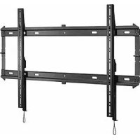
iCXPFM3B03 - Flat screen mount Chief - Free user manual and instructions
Find the device manual for free iCXPFM3B03 Chief in PDF.



| Product type | Wall mount for flat screen |
| Brand | Chief |
| Model | iCXPFM3B03 |
| Minimum VESA compatibility | 200 x 200 mm |
| Maximum load capacity | 79,4 kg |
| Stud spacing | 40,6 cm (16") or 61,0 cm (24") |
| Material | Steel |
| Finish | Black |
| Supported wall type | Wood studs, concrete, concrete block, brick |
| Maximum drywall thickness | 16 mm |
| Minimum drilling depth (concrete) | 8,25 mm |
| Locking system | Integrated locking latch |
| Security anti-theft | Eyelet for padlock or security cable (not included) |
| Cable management | Cable routing possible behind the screen |
| Number of mounting points | 4, 6 or 8 depending on the screen model |
| Tilt | Fixed (no tilt adjustment provided) |
| Box contents | Wall plate, mounting brackets, screws, washers, spacer rings, concrete anchors |
| Maintenance and cleaning | Clean with a soft, dry cloth. Do not use abrasive products. |
| Repairability | Spare parts available upon request from the manufacturer |
Frequently Asked Questions - iCXPFM3B03 Chief
User questions about iCXPFM3B03 Chief
0 question about this device. Answer the ones you know or ask your own.
Ask a new question about this device
Download the instructions for your Flat screen mount in PDF format for free! Find your manual iCXPFM3B03 - Chief and take your electronic device back in hand. On this page are published all the documents necessary for the use of your device. iCXPFM3B03 by Chief.
USER MANUAL iCXPFM3B03 Chief
Milestone AV Technologies, and its affiliated corporations and subsidiaries (collectively, "Milestone"), intend to make this manual accurate and complete. However, Milestone makes no claim that the information contained herein covers all details, conditions or variations, nor does it provide for every possible contingency in connection with the installation or use of this product. The information contained in this document is subject to change without notice or obligation of any kind. Milestone makes no representation of warranty, expressed or implied, regarding the information contained herein. Milestone assumes no responsibility for accuracy, completeness or sufficiency of the information contained in this document.
Chief® and Centris™ are trademarks of Milestone AV Technologies. All rights reserved.

IMPORTANT WARNINGS AND CAUTIONS!
WARNING: A WARNING alerts you to the possibility of serious injury or death if you do not follow the instructions.

CAUTION: A CAUTION alerts you to the possibility of damage or destruction of equipment if you do not follow the corresponding instructions.

WARNING: Failure to read, thoroughly understand, and follow all instructions can result in serious personal injury, damage to equipment, or voiding of factory warranty! It is the installer's responsibility to make sure all components are properly assembled and installed using the instructions provided.

WARNING: Failure to provide adequate structural strength for this component can result in serious personal injury or damage to equipment! It is the installer's responsibility to make sure the structure to which this component is attached can support five times the combined weight of all equipment. Reinforce the structure as required before installing the component. The wall to which the mount is being attached may have a maximum drywall thickness of 5/8'' (15.9mm).

WARNING: Exceeding the weight capacity can result in serious personal injury or damage to equipment! It is the installer's responsibility to make sure the combined weight of all components attached does not exceed 125 lbs (56.7kg) for the iCMPFM3 and iCLPFM3 or 175 lbs (79.4kg) for the iCXPFM3. Use with products heavier than the maximum weight indicated may result in collapse of the mount and its accessories causing possible injury.

AVISOS Y PRECAUCIONES IMPORANTES!

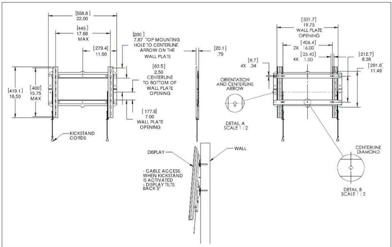
DIMENSIONS - iCMPFM3
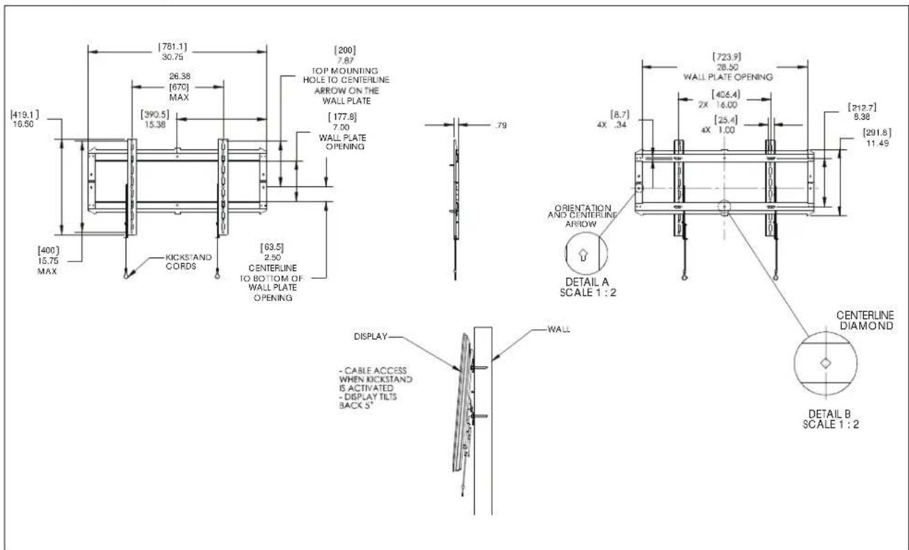
DIMENSIONS - iCLPFM3
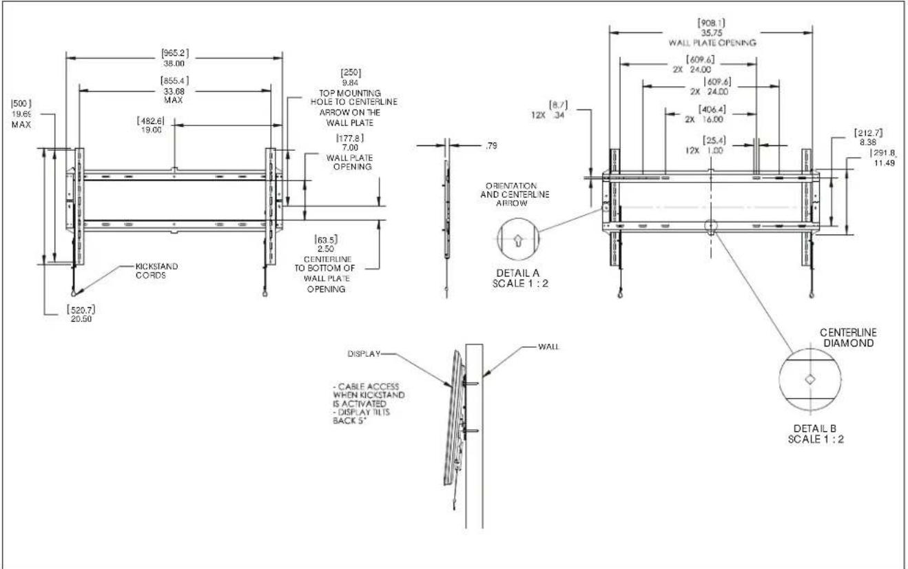
DIMENSIONS - iCXPFM3
| Tighten Fasater | |
| Apertar elemento de fiación | Stram fastispandingsblag |
| Befestigungstafistodien | Skriva & fäste |
| Apertar fixador | Krista klimne |
| Serrare il fissaggio | Dokreć/element mucijacy |
| Bewestigving vostrostan | Zajrjou Zivšobov |
| Serrao les fixdons | Baglanty: Sskgunn |
| Coakwre 3actezy | Rogtó meghuzaa |
| Lozen Fasater | |
| Atojer elemento de fiñado | Leger fastispandingsblag |
| Befestigungstaflös | Lasa fäste |
| Dasapertar fixador | Irotva klimne |
| Allentare il fissaggio | Poluszowac element mucijacy |
| Bewestigving losrazen | Xahápuşov Zivšobov |
| Dasensezles fixdations | Baglanty: Gevazin |
| Occhafte 3actezy | Rogtó hizitfassa |
| Philips Sowdthier | |
| Destinyilador Philips | Sigemskuetoehner |
| Kruzkitschzachsbrändera | Kryskužmeyjal |
| Chave de fondas Philips | Ristpólarnuviavn |
| Caddiavite a siddla | Sznobodt Krzyszakow |
| Krudropschvaevendraser | Konopálz Philips |
| Toumevis i pinta orucitome | Philips Tornavida |
| Otraipna | Callagfjo csaathzház |
| By Hand | |
| Amanio | Madhänden |
| Von Hand | Förhand |
| Cam a mão | Käsin |
| Amanoe | Reçnec |
| Mét de hand | Mić to xćpa |
| Alamain | El be |
| Pencil Mark | ||
| Mancar con lapiz | Byarimmarke | |
| Slittermarkierung | Pormmarkierung | |
| Mancar con lapiz | Rimmetty marki | |
| Segno a malita | Oznacranie olwkiem | |
| Potoodermaktaken | Zirukka με μukkla | |
| Marquapi au orayon | Kaimer liganti | |
| Mapka-Kapa-gaua | Cenzazajbóls | |
| Oril Holes | ||
| Partor | Bo rehul | |
| Bohrloch | Bo māl | |
| Fazer furo | Porausreid | |
| Praticare un tro | Otwr wiercory | |
| Gat boren | Adipronan emtcl | |
| Paraz un trou | Matkap Deligi | |
| OrapeCTRte Tpe-apoase | Lyukfurda | |
| Adjust | ||
| Ajustar | Juslar | |
| Einstellen | Juslara | |
| Ajustar | Stalst | |
| Regolaré | Wyrregulowad | |
| Aftstellen | P(pooquyur) | |
| Ajustar | Ayar | |
| Tpecnocoforea | Balililas | |
| Hex-Head Wrench | ||
| Llave de cabaiza hexagonal | Sekukantet sileuanegle | |
| Sedkhantachissel | Insexydokel | |
| Chave de cabaiza sotawada | Kusukoloakwain | |
| Chave esagonale | Khuz 2 lham szadolokatym | |
| Zesiantsteutali | Khod āzoyunnyj, kajakj | |
| Cló à tete hexagonale | Altagen Kafali (Allen) Anahart | |
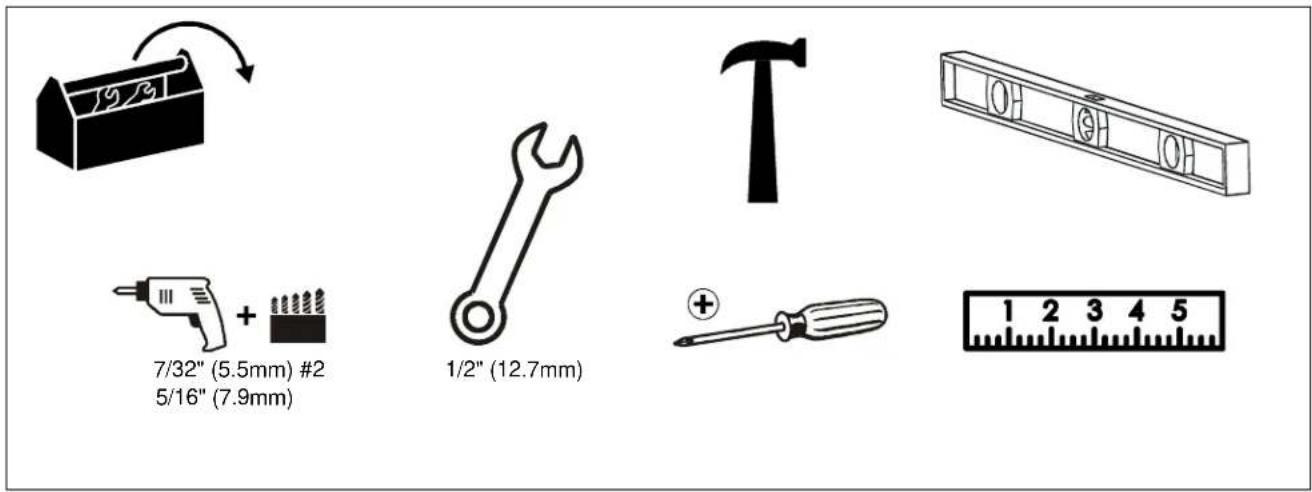
TOOLS REQUIRED FOR INSTALLATION
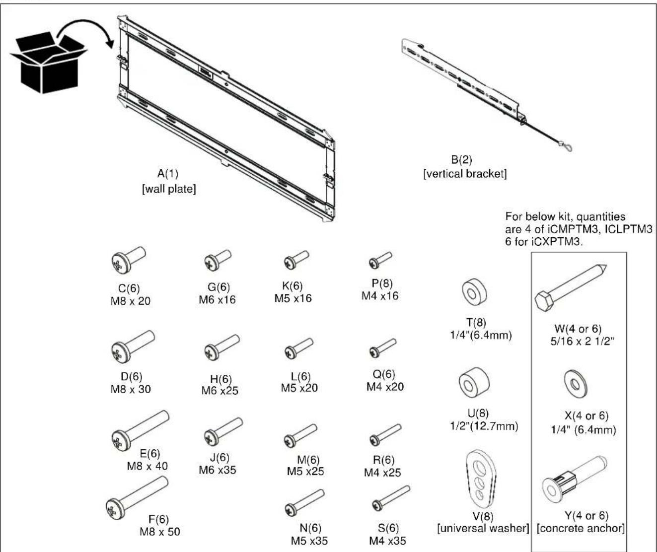
PARTS
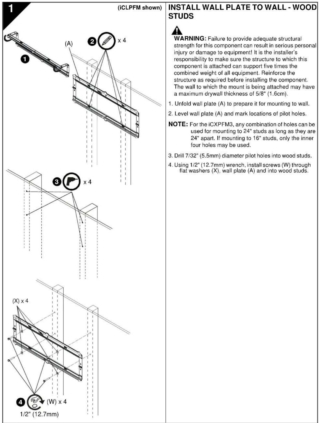
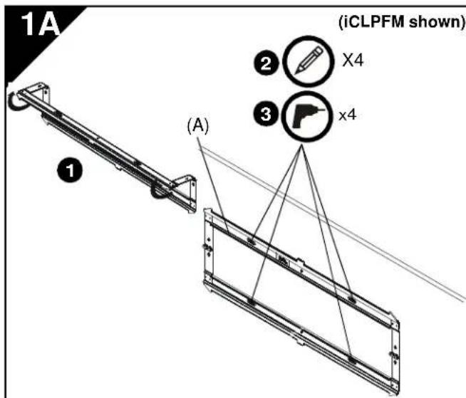
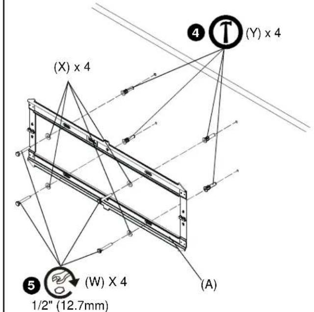
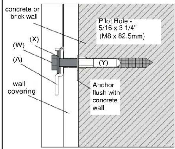
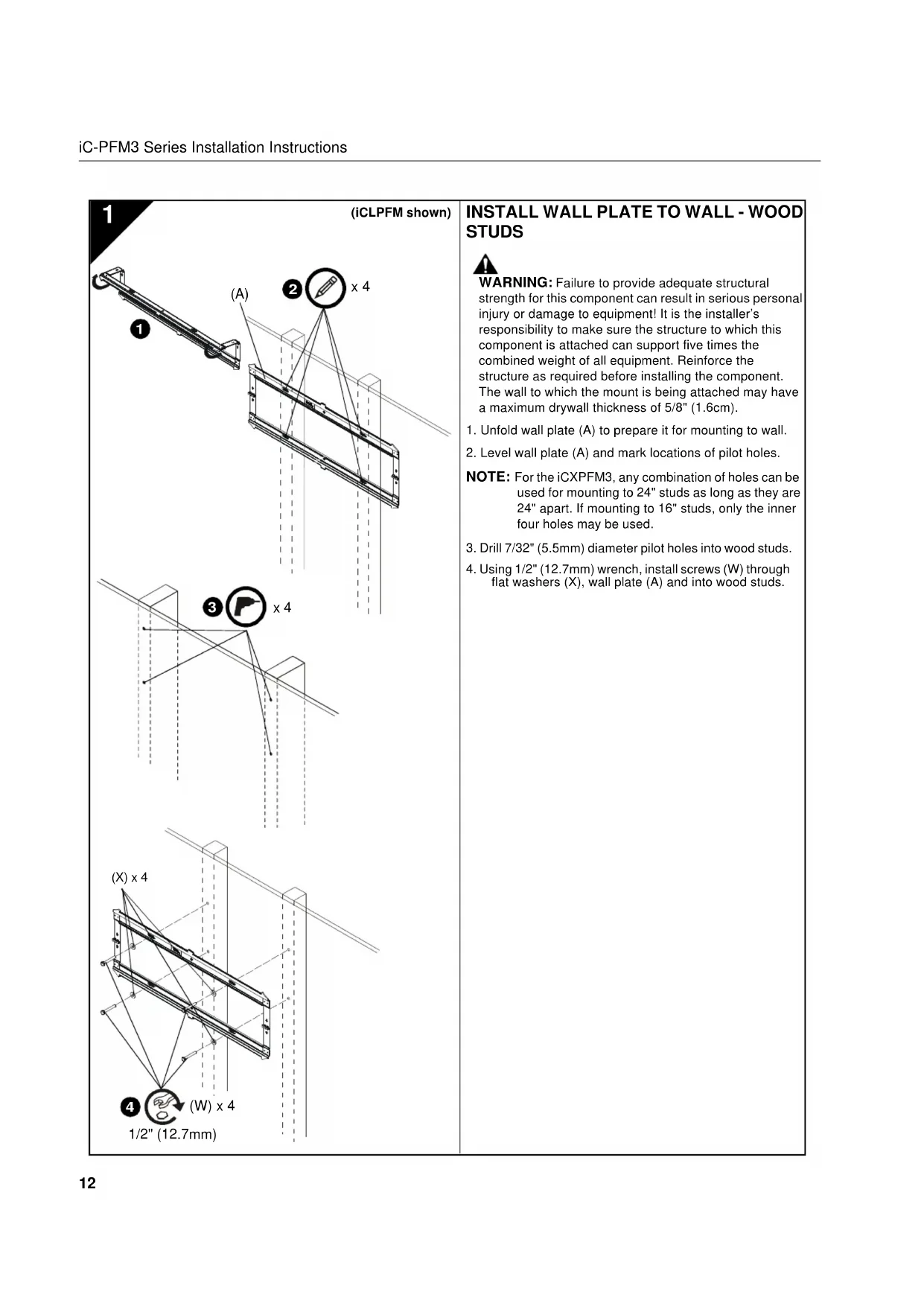
INSTALL WALL PLATE TO WALL - CONCRETE, CONCRETE BLOCK OR BRICK

WARNING: Failure to provide adequate structural strength for this component can result in serious personal injury or damage to equipment! It is the installer's responsibility to make sure the structure to which this component is attached can support five times the combined weight of all equipment. Reinforce the structure as required before installing the component. The wall to which the mount is being attached may have a maximum drywall thickness of 5/8'' (1.6cm).

WARNING: ELECTRICAL SHOCK HAZARD! CUTTING OR DRILLING INTO ELECTRICAL CORDS OR CABLES CAN CAUSE DEATH OR SERIOUS PERSONAL INJURY! ALWAYS make certain area behind mounting surface is free of electrical wires and cables before drilling or installing fasteners.

WARNING: EXPLOSION AND FIRE HAZARD! CUTTING OR DRILLING INTO GAS PLUMBING CAN CAUSE DEATH OR SERIOUS PERSONAL INJURY! ALWAYS make certain area behind mounting surface is free of gas, water, waste, or any other plumbing before cutting, drilling, or installing fasteners.
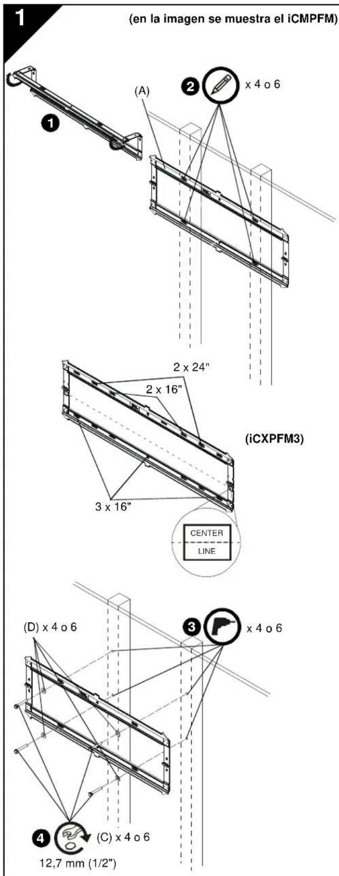
- Unfold wall plate (A) to prepare it for mounting to wall.
- Level wall plate (A) and mark locations of pilot holes at desired mounting location.
NOTE: For the iCXPFM3, use the inner four holes on wall plate for installation.
- Drill 5/16" (8mm) diameter pilot holes into wall at marked locations. Holes must be drilled at least 3 1/4 inches deep.
- Install four concrete anchors (Y) into drilled holes. Use a hammer to tap anchors into holes.
IMPORTANT ! : The anchors must be installed through any wall covering until flush with the concrete wall.
- Using 1/2'' (12.7mm) wrench, install screws (W) through flat washers (X), wall plate (A) and into concrete anchors (Y).
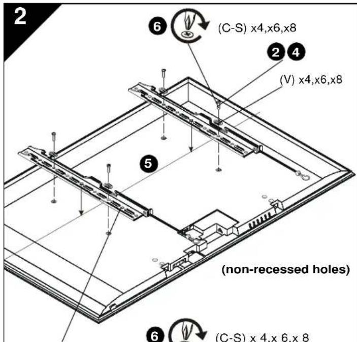
(B) × 2
(B) × 2
INSTALL BRACKETS TO DISPLAY

WARNING: The minimum hole pattern size is 100mm × 100mm for the iCMPFM3 and 200mm × 200mm for the iCLPFM3 and the iCXPFM3.
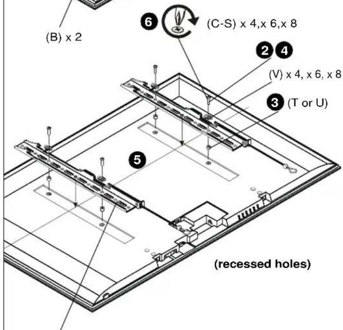
- Lay display face down on protective surface.

CAUTION: Using screws of improper diameter may damage your display! Proper screws will easily thread into display mounting holes.
- Select screw diameter by examining hardware (C-S) (8mm, 6mm, 5mm, or 4mm) and comparing with mounting holes on display.
- Select spacers:
If mounting holes are not recessed and both brackets (B) can lay flat against display, then no spacers are required.
- If mounting holes are recessed, or if protrusions prevent brackets (B) from laying flat, then spacers (T or U) must be used. Select shortest spacer which will provide adequate fill. All spacers must be same length.

CAUTION: Using screws of improper length may damage your display! Proper screws will have adequate thread engagement without contacting bottom of display mounting holes.
-
Select screw length:
-
Using your hand, insert SHORTEST length screw of selected diameter (C, G, K or P) through bracket (B), universal washer (V), selected spacer (T or U, if required), into display mounting hole. Do NOT thread screw into hole at this time.
-
Proper screw length requires base of screw head to protrude above flat washer a distance equal to or greater than the screw diameter. If screw length is inadequate, select longer screw. Select shortest screw which will protrude the required distance.
-
Place brackets (B) on display, ensuring:
-
Upper hooks are towards top of display.
-
Center of brackets (B) are as close to the center of the back of display as possible after being installed. Center of bracket is indicated by the diamond-shaped hole.
-
Using Phillips screwdriver, carefully install selected screws through universal washers (V), brackets (B), and spacers (T or U, if required), into display.
- Tighten all screws. Ensure all applicable display mounting holes (4, 6, or 8) are used.
INSTALL DISPLAY TO WALL PLATE

WARNING: Exceeding the weight capacity can result in serious personal injury or damage to equipment! It is the installer's responsibility to make sure the combined weight of all components attached does not exceed 125 lbs (56.7 kg) for the iCMPFM3 and iCLPFM3 or 175 lbs (79.4 kg) for the iCXPFM3. Use with products heavier than the maximum weight indicated may result in collapse of the mount and its accessories causing possible injury.

WARNING: Display may be very heavy! Ensure display can be safely lifted and maneuvered as required to install on wall plate. Failure to take adequate precautions can result in serious personal injury or damage to equipment!

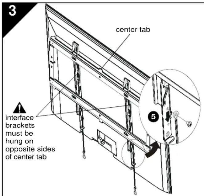
WARNING: Interface brackets must be hung on opposite sides of the center tab on wall plate!
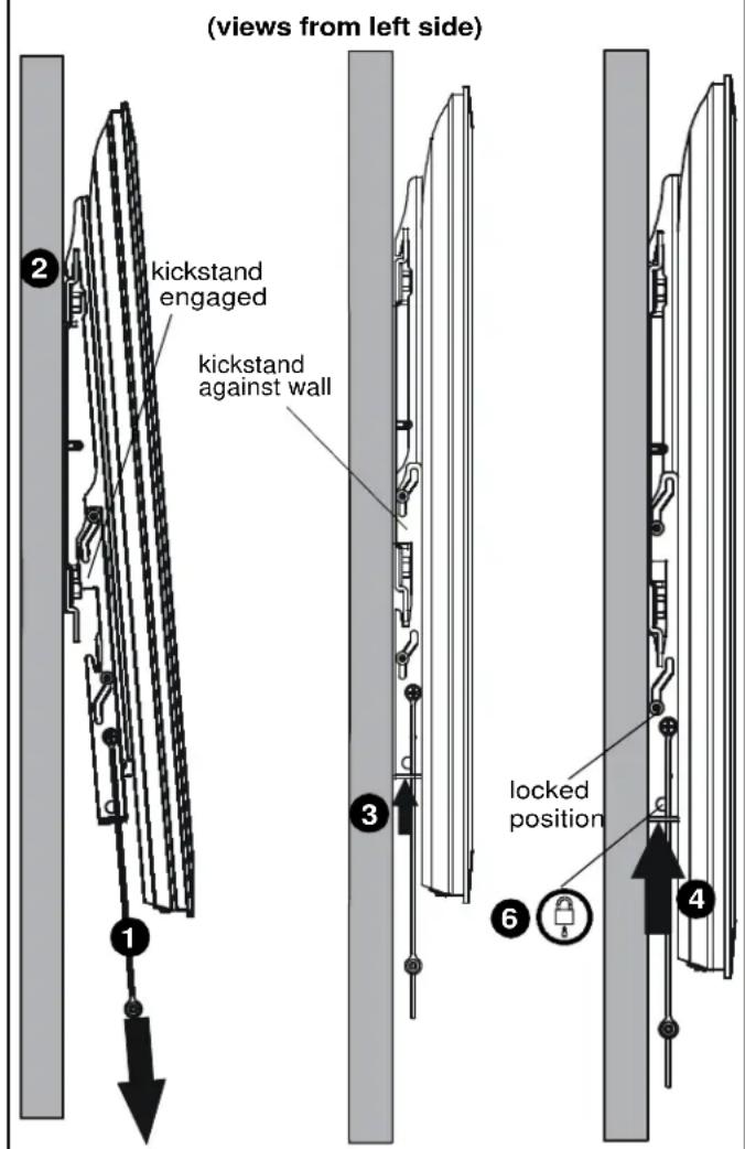
- Make sure interface brackets are in the kickstand position by pulling down on handles as far as possible.
- Hang display with brackets (B) on upper rail of wall plate (A). Kickstand should be engaged with lower portion of wall plate.
NOTE: Any cable management or rear display adjustments should be made when the display is resting on the kickstand.
- Unlock kickstand by pushing up on interface brackets until kickstand rests against the wall.
- Push up on the interface brackets further in order to lock display into position against wall.
NOTE: Straps can be either cut off or tucked behind display after installation is complete so that they will not be visible to the viewer.
- (Optional) The straps can be moved to the lower screw holes on interface brackets in order to improve access to the straps on larger displays.
- (Optional) Route padlock or cable lock (not included) through bottom holes on interface bracket to provide additional security.
INSTALLACION DE LA PLACA DE PARED EN LA PARED: MONTANTES DE MADERA

NOT: CYP17A2, montelukast drug product (continued)
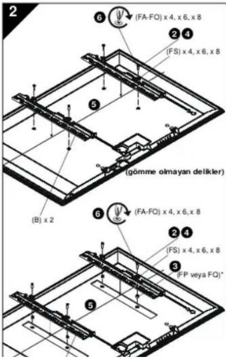
DESTEKLERI EKRANA MONTE ETME

UYARI: Minimum delik dizi zeni boyutu, iCMPFM3
igin 10.0 mm x 10.0 mm; iCLP FM3 ve iCXPFM3
iginse 200 mm x 200 mm.
- Ekani yuzistu bigimekoryucu biryuzeye yatrn

DIKKAT: Uygun olmayan captaki vidalan kullanlmasi ekrinan za zar veebilr! Uygun vidalar ekran montaj delkierine kolayca otur.
- Donanumilan (FA-FO) incoleyip ekrandaki montaj delkien ie karga trrak vida gapv secin (8mm,6mm,5mm vya 4mm
- Ara parcalanni seqin:
USA·8401 Eagle Creek Parkway, Suite 700·Savage, Minnesota 55378·800.572.1373
EMEA·+31(0)402668620
www.icmounts.com
©2011 Milestone AV Technologies. The iC Logo and StowAway are trademarks of Chief Manufacturing,
a products division of Milestone AV Technologies, a Duchossois Group Company. All rights reserved
Patents and patents pending. Milestone AV Technologies, Savage, MN 55378, USA 8800-002049 Rev 02
09/11
- IMPORTANT WARNINGS AND CAUTIONS
- AVISOS Y PRECAUCIONES IMPORANTES
- TOOLS REQUIRED FOR INSTALLATION
- PARTS
- INSTALL WALL PLATE TO WALL - CONCRETE, CONCRETE BLOCK OR BRICK
- INSTALL BRACKETS TO DISPLAY
- INSTALL DISPLAY TO WALL PLATE
- INSTALLACION DE LA PLACA DE PARED EN LA PARED: MONTANTES DE MADERA
- DESTEKLERI EKRANA MONTE ETME
Brand : Chief
Model : iCXPFM3B03
Category : Flat screen mount