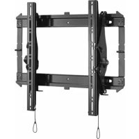
iCMPTM3B03 - Flat screen mount Chief - Free user manual and instructions
Find the device manual for free iCMPTM3B03 Chief in PDF.



| Product Type | Wall mount for flat screen |
| Brand | Chief |
| Model | iCMPTM3B03 |
| Maximum weight capacity | 56.7 kg |
| Material | Steel |
| VESA compatibility | 100x100 mm to 440x440 mm |
| Tilt | Adjustable with adjustable tension |
| Mounting types | Wood studs, concrete, concrete block, or brick |
| Number of studs | 2 studs (center spacing 40.6 cm) |
| Package contents | Wall plate, mounting brackets, screws, washers, anchors |
| Care and cleaning | Clean with a soft, dry cloth |
| Safety | Professional installation recommended; the structure must support 5 times the total weight |
| Spare parts and repairability | Screws, washers, and anchors included; parts available upon request |
| General information | Suitable for flat screens; easy installation with a level |
Frequently Asked Questions - iCMPTM3B03 Chief
User questions about iCMPTM3B03 Chief
0 question about this device. Answer the ones you know or ask your own.
Ask a new question about this device
Download the instructions for your Flat screen mount in PDF format for free! Find your manual iCMPTM3B03 - Chief and take your electronic device back in hand. On this page are published all the documents necessary for the use of your device. iCMPTM3B03 by Chief.
USER MANUAL iCMPTM3B03 Chief
Milestone AV Technologies, and its affiliated corporations and subsidiaries (collectively, "Milestone"), intend to make this manual accurate and complete. However, Milestone makes no claim that the information contained herein covers all details, conditions or variations, nor does it provide for every possible contingency in connection with the installation or use of this product. The information contained in this document is subject to change without notice or obligation of any kind. Milestone makes no representation of warranty, expressed or implied, regarding the information contained herein. Milestone assumes no responsibility for accuracy, completeness or sufficiency of the information contained in this document.
Chief® and Centris™ are trademarks of Milestone AV Technologies. All rights reserved.
IMPORTANT WARNINGS AND CAUTIONS!
WARNING: A WARNING alerts you to the possibility of serious injury or death if you do not follow the instructions.

CAUTION: A CAUTION alerts you to the possibility of damage or destruction of equipment if you do not follow the corresponding instructions.

WARNING: Failure to read, thoroughly understand, and follow all instructions can result in serious personal injury, damage to equipment, or voiding of factory warranty! It is the installer's responsibility to make sure all components are properly assembled and installed using the instructions provided.

WARNING: Failure to provide adequate structural strength for this component can result in serious personal injury or damage to equipment! It is the installer's responsibility to make sure the structure to which this component is attached can support five times the combined weight of all equipment. Reinforce the structure as required before installing the component. The wall to which the mount is being attached may have a maximum drywall thickness of 5/8" (15.9mm).

WARNING: Exceeding the weight capacity can result in serious personal injury or damage to equipment! It is the installer's responsibility to make sure the combined weight of all components attached does not exceed 125 lbs (56.7 kg) for the iCMPTM3 and iCLPTM3 or 175 lbs (79.4 kg) for the iCXPTM3. Use with products heavier than the maximum weight indicated may result in collapse of the mount and its accessories causing possible injury.

DIMENSIONS - iCMPTM3
![[406.4] 16.00 [506.5] 19.94 MAX [25.4] 1.00 [8.7] .34 [419] 16.50 [400] 15.75 [279.4] 11.00 [558.8] 22.00 [177.8] 7.00 WALL OPENING [200] 7.87 TOP MOUNTING HOLE TO CENTERLINE NOTCH ON WALL PLATE [131.8] 5.19 [212.7] 8.38 [63.5] 2.50 CENTERLINE TO BOTTOM OF WALL PLATE OPENING [49.9] 1.96 - CABLE ACCESS WHEN KICKSTAND IS ACTIVATED - TILTS BACK 5.4° 12° MAX TILT](/content/2026/02/354873/images/cb527f9e3fa56841d2d7297cd37c043e893d0752d29f7d927fe379ba3341ec97.jpg)
DIMENSIONS - iCLPTM3
![[609.6] 24.00 [406.4] 16.00 [728.8] 28.69 MAX [25.4] 1.00 [8.7] .34 [419] 16.50 [400] 15.75 [781.1] 30.75 [390.5] 15.38 [177.8] 7.00 WALL OPENING [200] 7.87 TOP MOUNTING HOLE TO CENTERLINE NOTCH ON WALL PLATE [131.8] 5.19 [212.7] 8.38 [63.5] 2.50 CENTERLINE TO BOTTOM OF WALL PLATE OPENING [49.9] 1.96 12° MAX TILT -CABLE ACCESS WHEN KICKSTAND IS ACTIVATED - TILTS BACK 5°](/content/2026/02/354873/images/d211b673c06dcd9c0da416a7a664c24ff7a254af3292383e20543b2f20963d02.jpg)
DIMENSIONS - iCXPTM3
![[812.8] 32.00 [609.6] 24.00 [406.4] 16.00 [25.4] 1.00 [913] 35.94 MAX [8.7] .34 [500] 19.68 [965.2] 38.00 [482.6] 19.00 [177.8] 7.00 WALL OPENING [131.8] 5.19 [212.7] 8.38 [63.5] 2.50 CENTERLINE TO BOTTOM OF WALL PLATE OPENING [250] 9.84 [49.9] 1.96 TOP MOUNTING HOLE TO CENTERLINE NOTCH ON WALL PLATE - CABLE ACCESS WHEN KICKSTAND IS ACTIVATED - TILTS BACK 5° 12° MAX TILT](/content/2026/02/354873/images/13059a063a39bdfbba275d9b59c5187f9d31f1f530905ef3437eea37c0e80235.jpg)
LEGEND
 | Tighten Fastener | Pencil Mark | |||
| Apretar elemento de fijación | Stram fastspændingsbeslag | Mancar con lapiz | Byaftimanie | ||
| Befestigungstal festzidien | Skruva å flaste | Siftmarkierung | Ponmmarkering | ||
| Apertar fixador | Kristå kinnike | Mancar com lapis | Primaty merlki | ||
| Semare il fissaggio | Doleşćić element mocujący | Segno a malta | Oznaczanie obwkiem | ||
| Bevestiging vastdralen | Izičýjuo Zuvčotyou | Potloodmehsken | Izrguði uč učkůjš | ||
| Serez les fixazons | Baglianty: Skiptinn | Marquage au oriyon | Kalern igared | ||
| Coxavre e Sacrosny | Rógritô meghuzásá | Mapka Kapauçava | Ceruzajeblós | ||
 | Lo asen Fastener | Drill Hole | |||
| Aflojar elemento de fijadón | Lesger fastspændingsbeslag | Parlor ar | Borehul | ||
| Befestigungstell össen | Lassa flaste | Bdnloch | Borna hál | ||
| Dasaportar fixador | Imota kinnike | Fazer funo | Porausnikiš | ||
| Alentare il fissaggio | Poluzować element mocujący | Praticare un bro | Olwór wiercony | ||
| Bevestiging losdralen | Xahápučen, Zuvčotyou | Gat boren | Adtrýpon omíž | ||
| Das serez les fixations | Baglianty: Govjetin | Parasz un trau | Matkap Deligi | ||
| Ocnaføre Sacrosny | Rógritô klazitása | Ortæpctrne Tprewposen | Lyukürdás | ||
| [IMAGE] | Philips Screwdriver | Adjust | |||
| Dostanfilador Philips | Sjemeskluetraakler | Ajustar | Justar | ||
| Kreuzschitzschraubendrihar | Krysakuvmejel | Einstellen | Justara | ||
| Chave de fondas Philips | Ristip ákruvišain | Ajustar | Sátsáš | ||
| Cacladite a stalla | Šrubdkręt krzyśakowy | Regolare | Wynogubowac | ||
| Knudskapschroevendraiser | Konrotěk Philips | Aftstellen | Пропосяруonyt | ||
| Tournevis āp dinte oruforme | Philips Tomavida | Ajustar | Ayar | ||
| Omaepna | Callagląji csaherhizó | Prwocnocoßurea | Balàltítás | ||
| [X768] | By Hand | Hex Head Wrench | |||
| A mano | Medhänden | Llave de cabza hexagonal | Sokukantet skruenagle | ||
| Von Hand | För hand | Sedskantachnüssel | Insexnydkel | ||
| Com a mão | Klain | Chave de oboça sextaveda | Kuustokoloavain | ||
| A mano | Recznie | Chave esagonale | Klusz z libam szedokutnym | ||
| Met de hand | Mc ro yólş | Zaskantsteutel | Klzd čpayuwelýs kepalýs | ||
| Ála main | El lle | Cló à tête hexagonale | Altogen Katal (Allen) Anahtar | ||
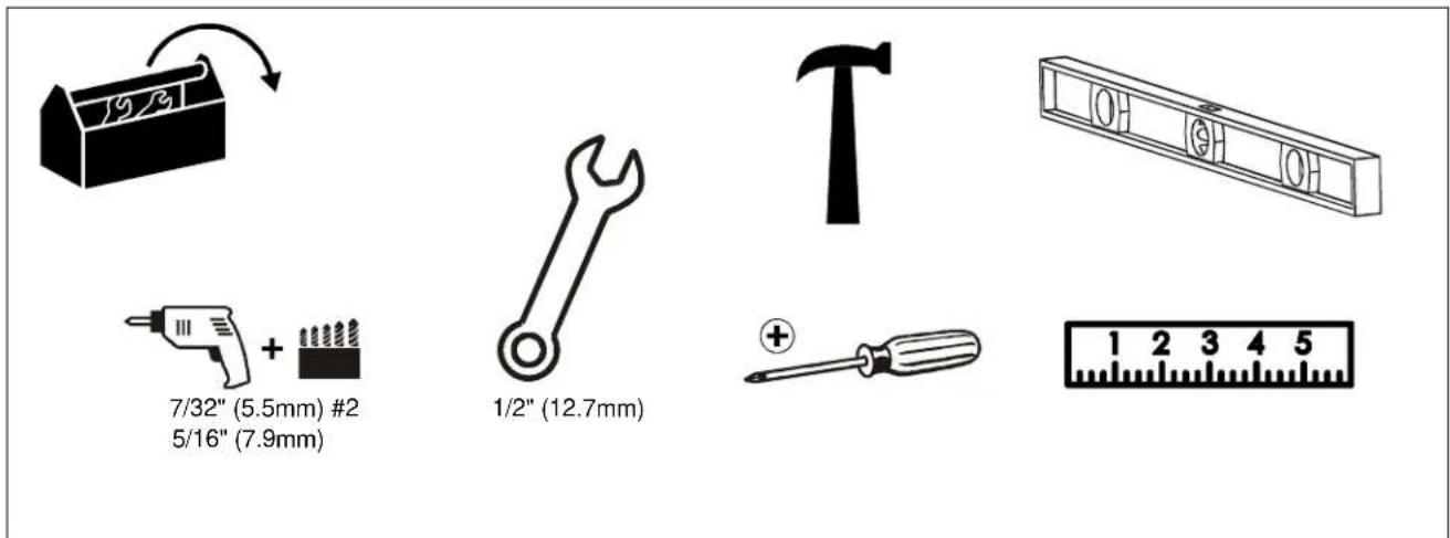
TOOLS REQUIRED FOR INSTALLATION
PARTS
![For below kit, quantities A(1) [wall plate] (iCXPTM3 shown) B(1) [right upright] C(1) [left upright]](/content/2026/02/354873/images/bf1410657b9af23a675d445634c6c283804259944b0e758557dd3aa7d2c8d368.jpg)
For below kit, quantities
are 4 of iCMPTM3. ICLPTM3
6 for iCXPTM3.
![G(1) Hardware Bag D(4 or 6) 5/16 x 2 1/2" E(4 or 6) 1/4" (6.4mm) F(4 or 6) [concrete anchor] GA(8) M4 x 16mm GE(6) M5 x16mm GI(6) M6 x16mm GL(6) M8 x 20mm GP(8) 1/4"(6.4mm) GB(6) M4 x 20mm GF(6) M5 x20mm GJ(6) M6 x 25mm GM(6) M8 x 30mm GQ(8) 1/2"(12.7mm) GC(6) M4 x 25mm GG(6) M5 x25mm GK(6) M6 x 35mm GN(6) M8 x 40mm GD(6) M4 x 35mm GH(6) M5 x 35mm GO(6) M8 x 50mm GS(8) [universal washer]](/content/2026/02/354873/images/d5a34eb2989994bc36f0b6a1c0f19e61f2526a16f236d0f26b7e9965b62bd6d1.jpg)
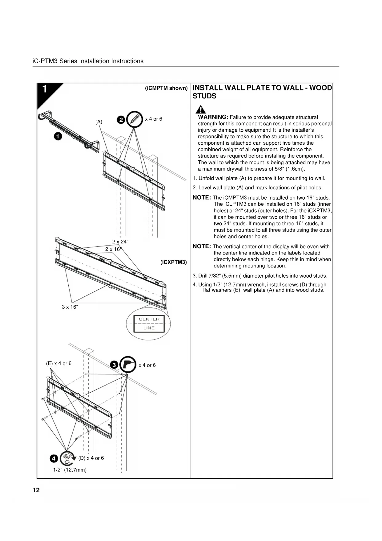
1
(iCMPTM shown)
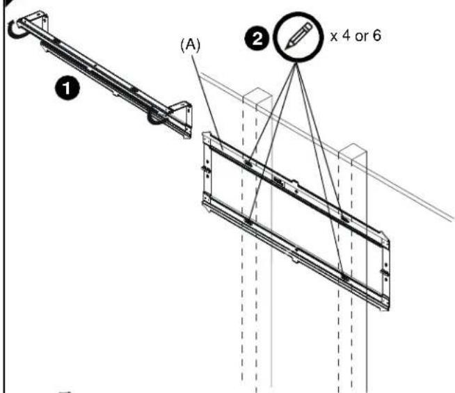
INSTALL WALL PLATE TO WALL - WOOD STUDS

WARNING: Failure to provide adequate structural strength for this component can result in serious personal injury or damage to equipment! It is the installer's responsibility to make sure the structure to which this component is attached can support five times the combined weight of all equipment. Reinforce the structure as required before installing the component. The wall to which the mount is being attached may have a maximum drywall thickness of 5/8" (1.6cm).
- Unfold wall plate (A) to prepare it for mounting to wall.
- Level wall plate (A) and mark locations of pilot holes.
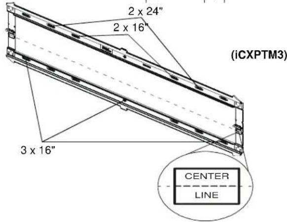
NOTE: The iCMPTM3 must be installed on two 16" studs. The iCLPTM3 can be installed on 16" studs (inner holes) or 24" studs (outer holes). For the iCXPTM3, it can be mounted over two or three 16" studs or two 24" studs. If mounting to three 16" studs, it must be mounted to all three studs using the outer holes and center holes.
NOTE: The vertical center of the display will be even with the center line indicated on the labels located directly below each hinge. Keep this in mind when determining mounting location.
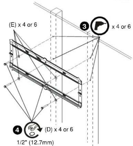
- Drill 7/32" (5.5mm) diameter pilot holes into wood studs.
- Using 1/2" (12.7mm) wrench, install screws (D) through flat washers (E), wall plate (A) and into wood studs.
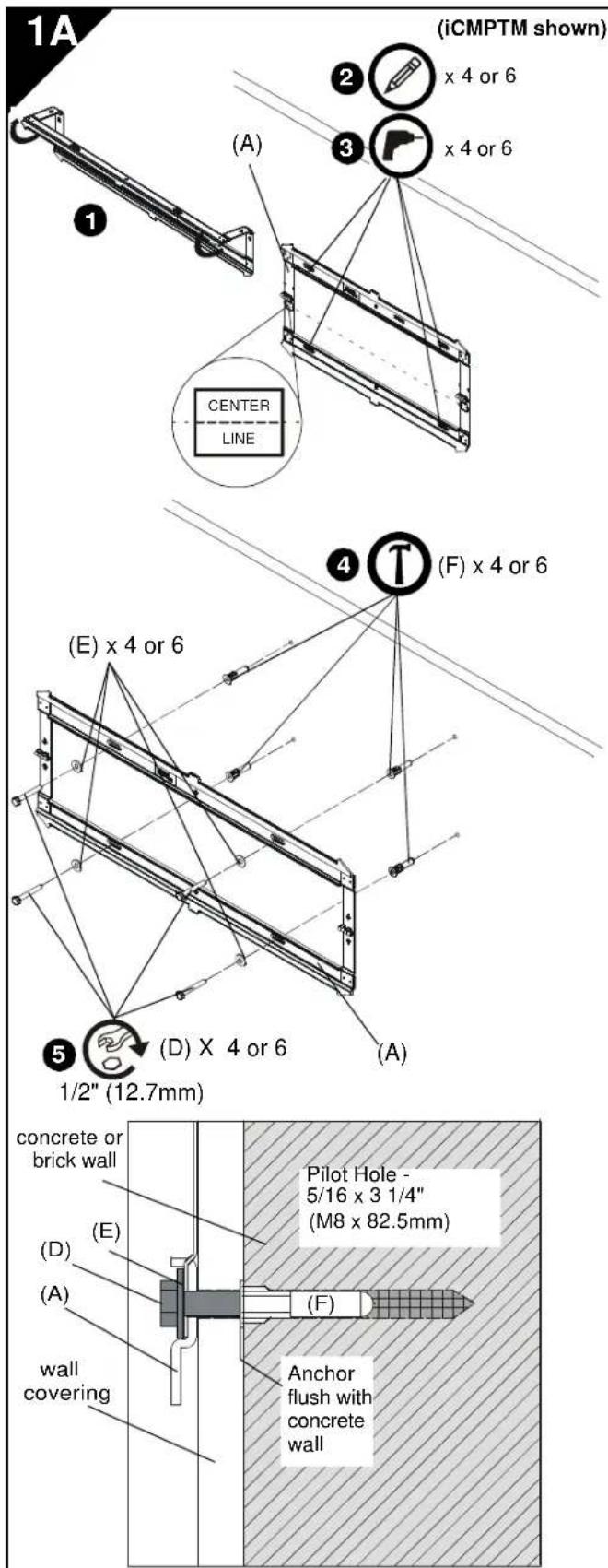
INSTALL WALL PLATE TO WALL - CONCRETE, CONCRETE BLOCK OR BRICK

WARNING: Failure to provide adequate structural strength for this component can result in serious personal injury or damage to equipment! It is the installer's responsibility to make sure the structure to which this component is attached can support five times the combined weight of all equipment. Reinforce the structure as required before installing the component. The wall to which the mount is being attached may have a maximum drywall thickness of 5/8" (1.6cm).

WARNING: ELECTRICAL SHOCK HAZARD! CUTTING OR DRILLING INTO ELECTRICAL CORDS OR CABLES CAN CAUSE DEATH OR SERIOUS PERSONAL INJURY! ALWAYS make certain area behind mounting surface is free of electrical wires and cables before drilling or installing fasteners.

WARNING: EXPLOSION AND FIRE HAZARD! CUTTING OR DRILLING INTO GAS PLUMBING CAN CAUSE DEATH OR SERIOUS PERSONAL INJURY! ALWAYS make certain area behind mounting surface is free of gas, water, waste, or any other plumbing before cutting, drilling, or installing fasteners.
- Unfold wall plate (A) to prepare it for mounting to wall.
- Level wall plate (A) and mark locations of pilot holes at desired mounting location.
NOTE: For the iCLPTM3, either the inner or outer four holes may be used.
NOTE: For the iCXPTM3, use the outer four holes and the two middle holes on wall plate for installation.
NOTE: The vertical center of the display will be even with the center line indicated on the labels located directly below each hinge. Keep this in mind when determining mounting location.
-
Drill 5/16" (8mm) diameter pilot holes into wall at marked locations. Holes must be drilled at least 3-1/4 inches deep.
-
Install concrete anchors (F) into drilled holes. Use a hammer to tap anchors into holes.
IMPORTANT ! : The anchors must be installed through any wall covering until flush with the concrete wall.
- Using 1/2" (12.7mm) wrench, install screws (D) through flat washers (E), wall plate (A) and into concrete anchors (F).
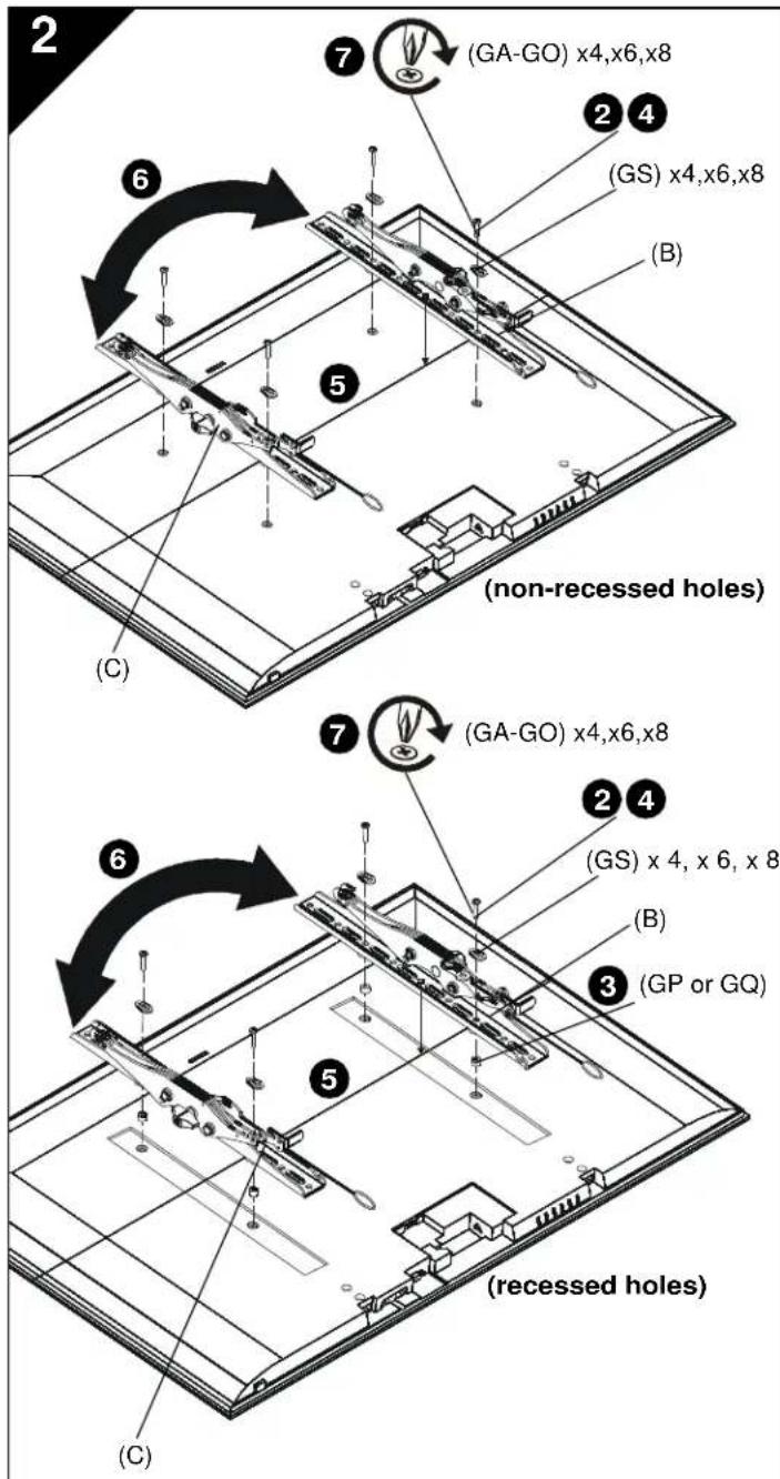
INSTALL BRACKETS TO DISPLAY

WARNING: The minimum hole pattern size is 100mm x 100mm for the iCMPTM3 and 200mm x 200mm for the iCLPTM3 and the iCXPTM3.
- Lay display face down on protective surface.

CAUTION: Using screws of improper diameter may damage your display! Proper screws will easily thread into display mounting holes.
-
Select screw diameter by examining hardware (GA-GO) (8mm, 6mm, 5mm, or 4mm) and comparing with mounting holes on display.
-
Select spacers:
-
If mounting holes are not recessed and both brackets (B and C) can lay flat against display, then no spacers are required.
- If mounting holes are recessed, or if protrusions prevent brackets (B and C) from laying flat, then spacers (GP or GQ) must be used.

CAUTION: Using screws of improper length may damage your display! Proper screws will have adequate thread engagement without contacting bottom of display mounting holes.
-
Select screw length:
-
Using your hand, insert SHORTEST length screw of selected diameter (GA, GE, GI or GL) through brackets (B and C), universal washer (GS), selected spacer (GP or GQ, if required), into display mounting hole. Do NOT thread screw into hole at this time.
-
Proper screw length requires base of screw head to protrude above flat washer a distance equal to or greater than the screw diameter. If screw length is inadequate, select longer screw. Select shortest screw which will protrude the required distance.
-
Place brackets (B and C) on display, ensuring:
• Upper hooks are towards top of display.
- Center of brackets (B and C) are as close to the center of the back of display as possible after being installed. Center of bracket is indicated by the diamond-shaped hole.
- If installing display with wide hole pattern, it may be necessary to swap the uprights (B and C). See Switching Interface Brackets section for details.
- Using Phillips screwdriver, carefully install selected screws through universal washers (GS), brackets (B and C), and spacers (GP or GQ, if required), into display.
- Tighten all screws. Ensure all applicable display mounting holes (4, 6, or 8) are used.
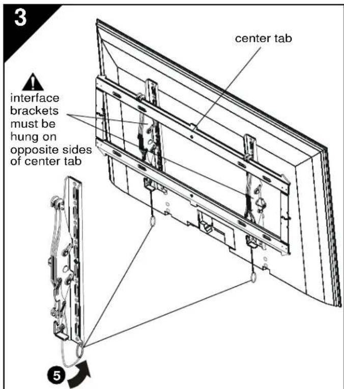
INSTALL DISPLAY TO WALL PLATE

WARNING: Exceeding the weight capacity can result in serious personal injury or damage to equipment! It is the installer's responsibility to make sure the combined weight of all components attached does not exceed 125 lbs (56.7 kg) for the iCMPTM3 and iCLPTM3 or 175 lbs (79.4 kg) for the iCXPTM3. Use with products heavier than the maximum weight indicated may result in collapse of the mount and its accessories causing possible injury.

WARNING: Display may be very heavy! Ensure display can be safely lifted and maneuvered as required to install on wall plate. Failure to take adequate precautions can result in serious personal injury or damage to equipment!

WARNING: Interface brackets must be hung on opposite sides of the center tab on wall plate!
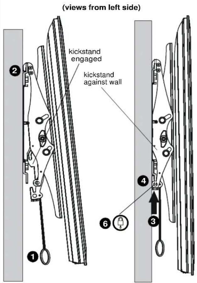
- Make sure interface brackets are in the kickstand position by pulling down on handles as far as possible.
- Hang display with brackets (B and C) on upper rail of wall plate (A). Kickstand should be engaged with lower portion of wall plate.
NOTE: Any cable management or rear display adjustments should be made when the display is resting on the kickstand. - Unlock kickstand by pushing up on interface brackets until kickstand rests against the wall.
- Push up on the interface brackets further in order to lock display into position against wall.
- Straps can be tucked behind display on notch on interface brackets (B and C) after installation is complete so that they will not be visible to the viewer.
- (Optional) Route padlock or cable lock (not included) through bottom holes on interface bracket to provide additional security.
4
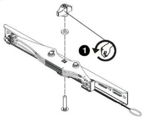
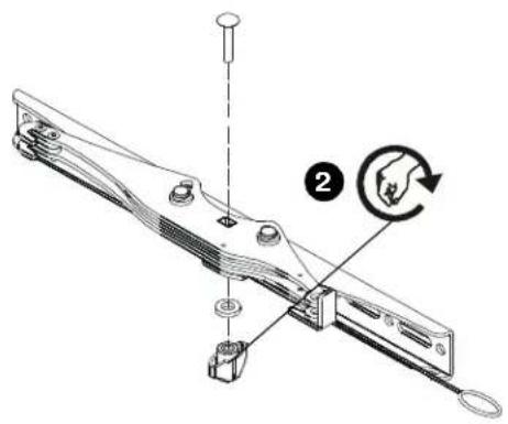
Switching Interface Brackets (Optional)
For wide hole patterns, interface brackets must be reversed. See Table 1 below to determine if this is necessary.
Table 1: Hole Pattern Width
| Model # | normal installation swap uprights | |
| iCMPTM3 100-44 | 0mm 441-506mm | |
| iCLPTM3 200-66 | 3mm 664-728.8mm | |
| iCXPTM3 200-84 | 7mm 848-913mm | |
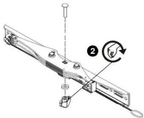
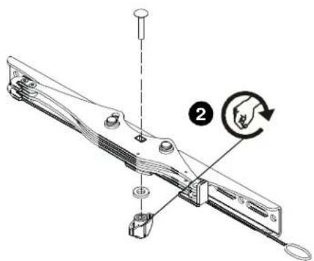
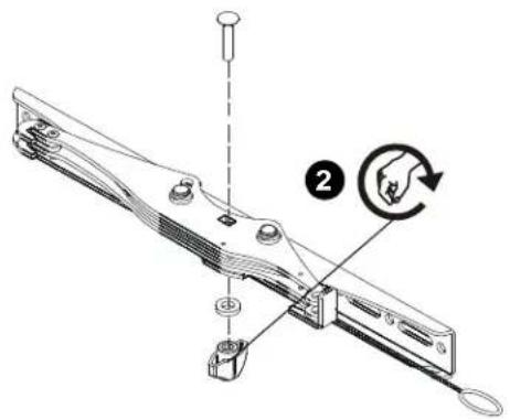
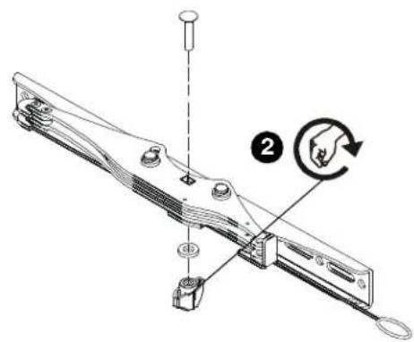
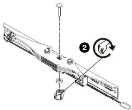
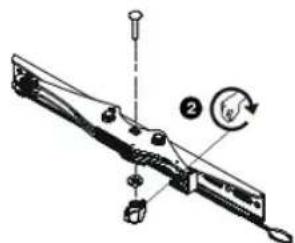
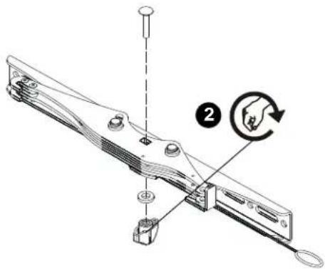
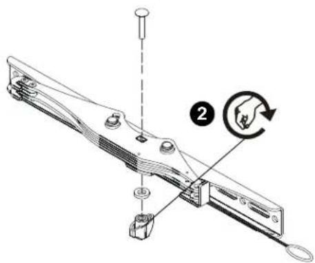
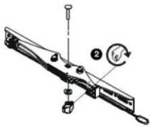
- Remove the tilt tension knob, washer and screw from interface bracket.
IMPORTANT ! : Hold the brackets steady when removing the knob, washer and screw from interface bracket to prevent internal washers from falling out. If internal washers do fall out, they must be reinserted in proper position before reinstalling knob on the other side! - Replace the knob, washer and screw in the opposite order.
- Repeat for the other interface bracket.
- Install interface brackets according to instructions in Section 2.
5
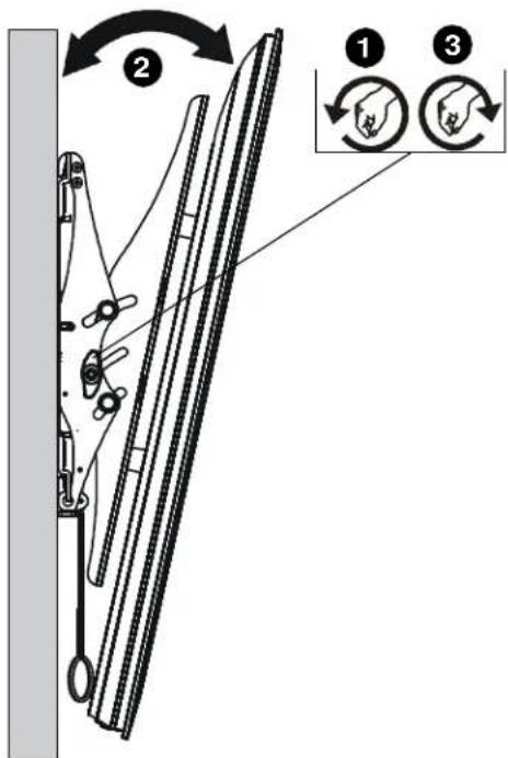
Tilt Adjustment
- Adjust tilt tension adjustment knobs to desired tension.
- Adjust tilt of display by pulling the top of display away from the wall until desired tilt position is reached.
- Tighten tilt tension adjustment knobs to secure tilt position.
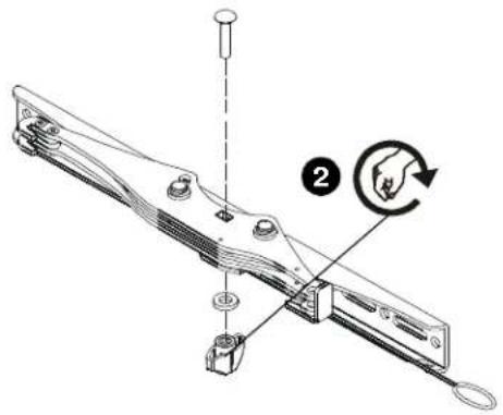
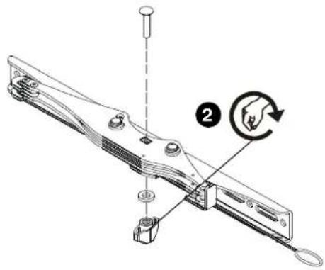
Ombytning af interfacebeslag (valgfrit)
Vippejustering
Kallistuksen säätö
Ρύθμιση κλίσης
Eğim Ayarı
©2012 Milestone AV Technologies. The iC Logo and StowAway are trademarks of Chief Manufacturing,
a products division of Milestone AV Technologies, a Duchossois Group Company. All rights reserved
Patents and patents pending. Milestone AV Technologies, Savage, MN 55378, USA
01/12
8800-002041 Rev 03

- IMPORTANT WARNINGS AND CAUTIONS!
- INSTALL WALL PLATE TO WALL - WOOD STUDS
- INSTALL WALL PLATE TO WALL - CONCRETE, CONCRETE BLOCK OR BRICK
- INSTALL BRACKETS TO DISPLAY
- INSTALL DISPLAY TO WALL PLATE
- Switching Interface Brackets (Optional)
- Tilt Adjustment
- Ombytning af interfacebeslag (valgfrit)
- Vippejustering
- Kallistuksen säätö
- Ρύθμιση κλίσης
- Eğim Ayarı
Brand : Chief
Model : iCMPTM3B03
Category : Flat screen mount