
iCMPTM3B02 - Flat screen mount Chief - Free user manual and instructions
Find the device manual for free iCMPTM3B02 Chief in PDF.

User questions about iCMPTM3B02 Chief
0 question about this device. Answer the ones you know or ask your own.
Ask a new question about this device
Download the instructions for your Flat screen mount in PDF format for free! Find your manual iCMPTM3B02 - Chief and take your electronic device back in hand. On this page are published all the documents necessary for the use of your device. iCMPTM3B02 by Chief.
USER MANUAL iCMPTM3B02 Chief
Milestone AV Technologies, and its affiliated corporations and subsidiaries (collectively, "Milestone"), intend to make this manual accurate and complete. However, Milestone makes no claim that the information contained herein covers all details, conditions or variations, nor does it provide for every possible contingency in connection with the installation or use of this product. The information contained in this document is subject to change without notice or obligation of any kind. Milestone makes no representation of warranty, expressed or implied, regarding the information contained herein. Milestone assumes no responsibility for accuracy, completeness or sufficiency of the information contained in this document.
Chief® and Centris™ are trademarks of Milestone AV Technologies. All rights reserved.

IMPORTANT WARNINGS AND CAUTIONS!
WARNING: A WARNING alerts you to the possibility of serious injury or death if you do not follow the instructions.

CAUTION: A CAUTION alerts you to the possibility of damage or destruction of equipment if you do not follow the corresponding instructions.

WARNING: Failure to read, thoroughly understand, and follow all instructions can result in serious personal injury, damage to equipment, or voiding of factory warranty! It is the installer's responsibility to make sure all components are properly assembled and installed using the instructions provided.

WARNING: Failure to provide adequate structural strength for this component can result in serious personal injury or damage to equipment! It is the installer's responsibility to make sure the structure to which this component is attached can support five times the combined weight of all equipment. Reinforce the structure as required before installing the component. The wall to which the mount is being attached may have a maximum drywall thickness of 5/8'' (15.9mm).

WARNING: Exceeding the weight capacity can result in serious personal injury or damage to equipment! It is the installer's responsibility to make sure the combined weight of all components attached does not exceed 125 lbs (56.7 kg) for the iCMPTM3 and iCLPTM3 or 175 lbs (79.4 kg) for the iCXPTM3. Use with products heavier than the maximum weight indicated may result in collapse of the mount and its accessories causing possible injury.

AVISOS Y PRECAUCIONES IMPORANTES!

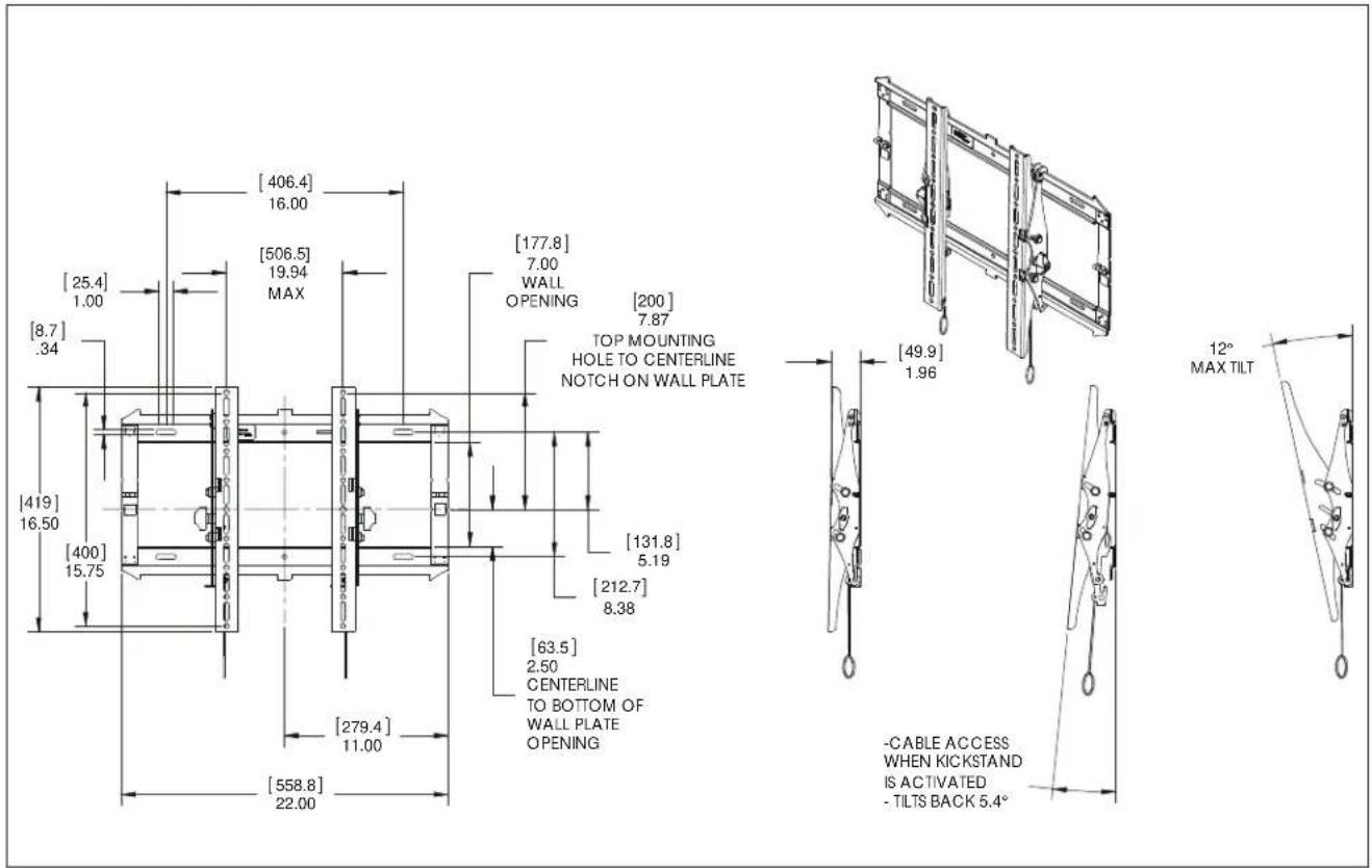
DIMENSIONS - iCMPTM3
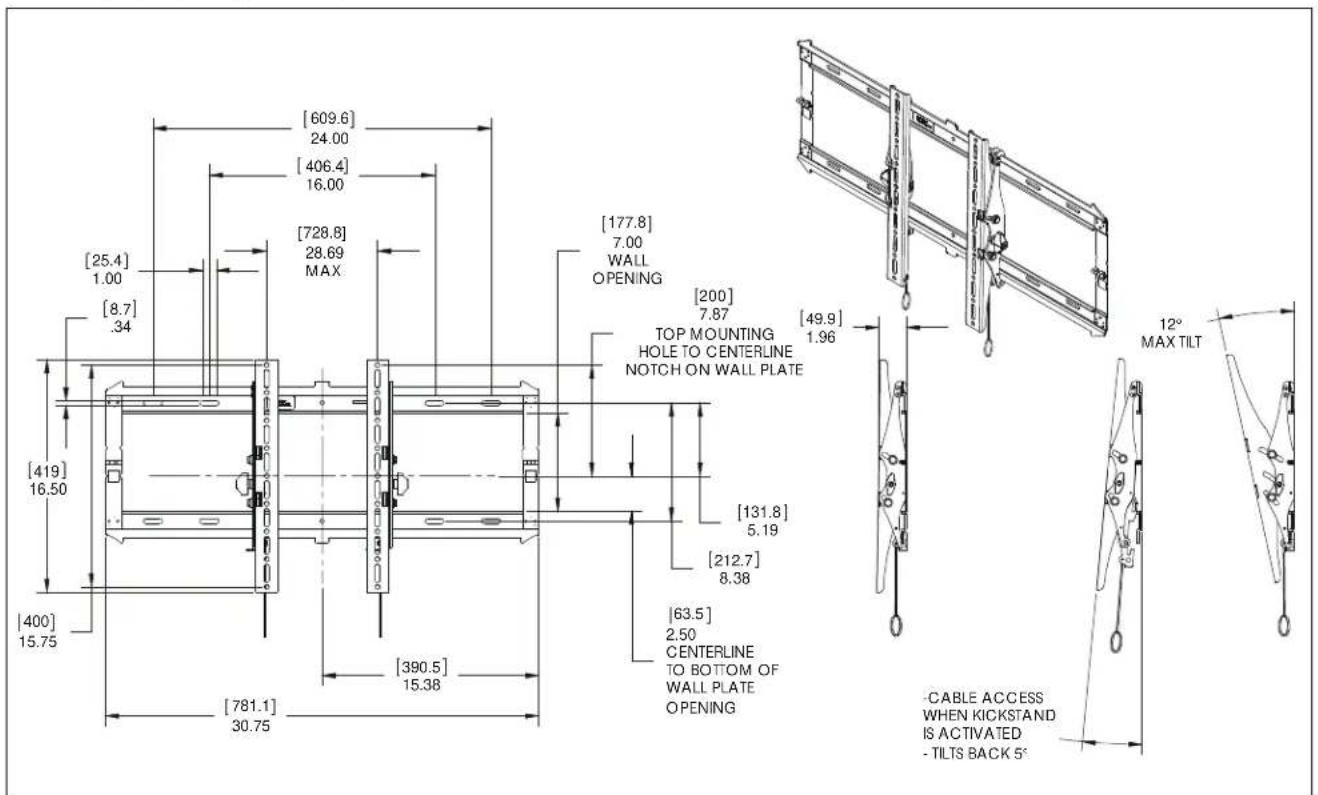
DIMENSIONS - iCLPTM3
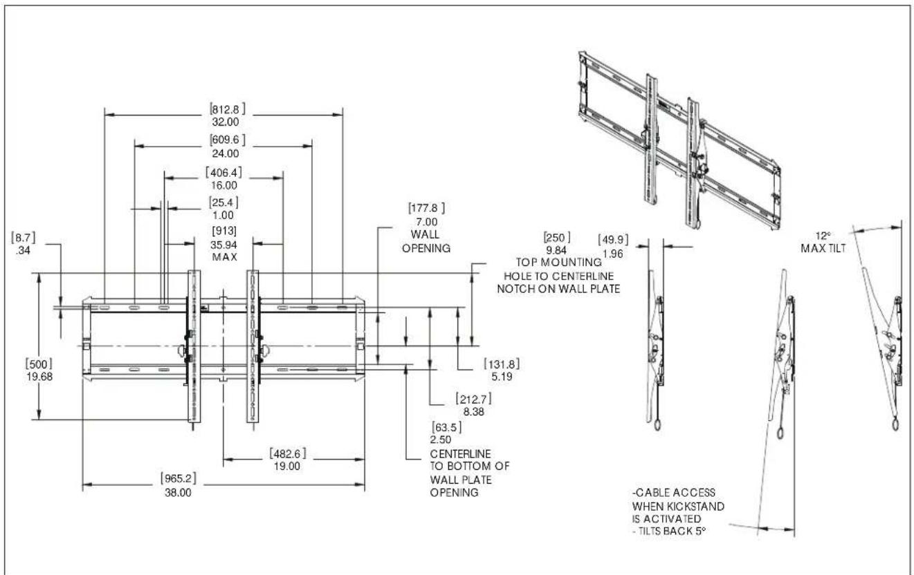
DIMENSIONS - iCXPTM3
| Tighten Fastener | |
| Apertar elemento de f山坡 | Stram fastspanendgeslag |
| Befestigungstaf festrochhen | Skiuva at tiske |
| Apertar fiscador | Krista klimne |
| Serre il fiscaggo | Dolegicl element mcucjagy |
| Bevestigung vostraiaian | Zajpjuu Zuvkojou |
| Serron los fixationes | Baglantnyi Skugren |
| Cocaware 3acteowy | Rogaló meghuzala |
| Lodon Passerier | |
| Atojer elemento de f山坡 | Lager fastspanendgeslag |
| Befostigungsstaf lsken | Laska fiske |
| Dasaportar fixador | Irotsa klimne |
| Allentare il fiscaggo | Poluzowac element mojculagy |
| Bevestigung los fixationes | Xahkupovn Zuvkojou |
| Dasemazlos fixationes | Baglantnyi Gavpatin |
| Ocnafuse 3acteowy | Rogaló hizulisa |
| Philips Screwdriver | |
| Destor nilador Philips | Sigemskuetoakker |
| Kruzschlitzschraubender | Kryskauwumeyal |
| Chave de fondas Philips | Ristpänuunvivain |
| Cadavite a stalla | Srubokraj Kryskalovy |
| Kruskaposdraevandraser | Kronopäts Philips |
| Toumevis a panta oncuforte | Philips Tornavida |
| Oraepna | Callagfej ciswerhráž |
| By Hand | |
| Amanco | Madhändon |
| Von Hand | För hand |
| Cam a mão | Käsin |
| Amanco | Reçnie |
| Mat de hand | Mio to xüp |
| Alamain | El be |
| Pencil Mark | ||
| Marcar com tapiz | Bya nirmarie | |
| Stiftmarkeinung | Pormmarkveuhr | |
| Marcar com tapis | Rimetti merita | |
| Segno a matta | Oznacranie okwiem | |
| Potoodemkraken | Izzydka iu okudji | |
| Marquage au crayon | Kalem larieni | |
| Mapka/Kaplanigaua | Ceruzajekliks | |
| Ort Hole | ||
| Portar | Borehul | |
| Bedrioch | Bona hal | |
| Fazer furo | Porausniki | |
| Praticare un tro | Owdr wency | |
| Gat boren | Adroponi emirici | |
| Poroz un trou | Matkap Deligi | |
| Oraeporte Tpoavposen | Lyukuridis | |
| Adjust | ||
| Ajuster | Juslar | |
| Einstellen | Juslara | |
| Ajuster | Stalsta | |
| Regolaro | Wyrregulowak | |
| Astatien | Pipocopyrj | |
| Ajuster | Ayar | |
| Flucnoco&ureo | Balilhas | |
| Hex-Head Wrench | ||
| Lave de caba hexagonal | Sekkurtet sieueneagle | |
| Sedskartantachioel | Insoenyckel | |
| Chave de caba oseotavada | Kusikolokovain | |
| Chave esagonale | Kiust 2 ribam szadokatym | |
| Zeskantleutel | Khošć zojayunčić kajaklç | |
| Clá-téte hexagonale | Altgem Kafali (Allen) Anahtar | |
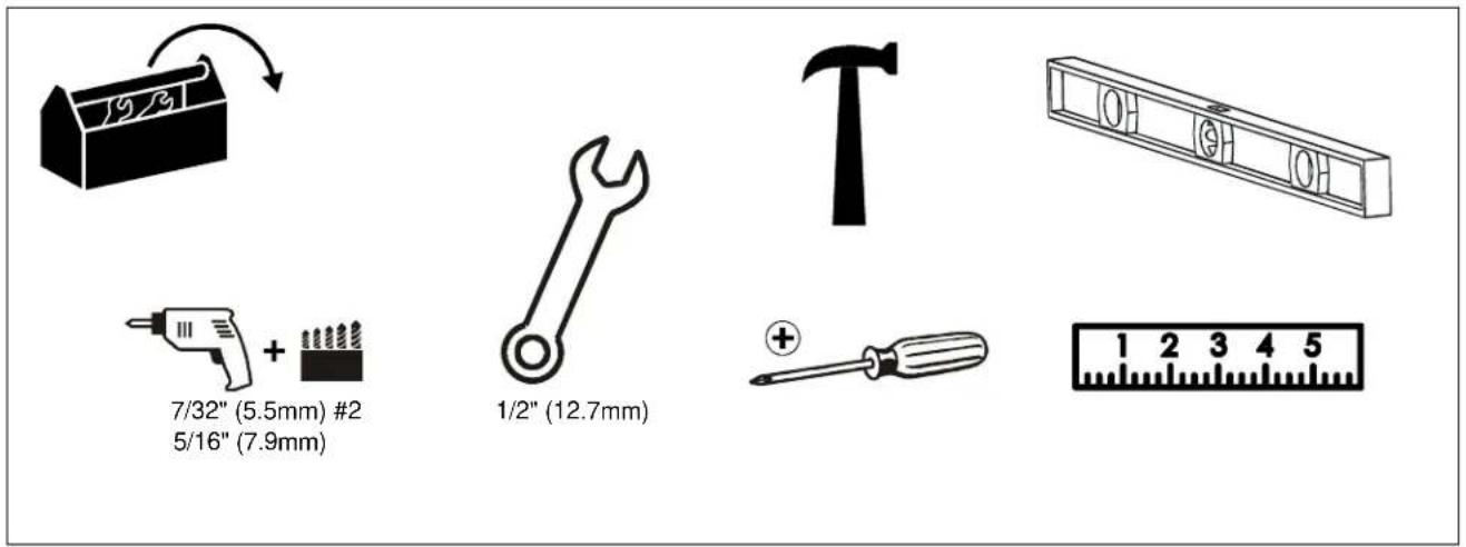
TOOLS REQUIRED FOR INSTALLATION
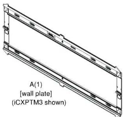
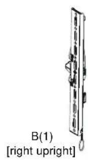
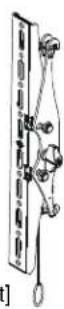
PARTS

C(1) [left upright]
For below kit, quantities are 4 of iCMPTM3, ICLPTM3 6 for iCXPTM3.
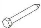
D(4 or 6) 5/16 x 2 1/2"

E(4 or 6) 1 / 4'' (6.4mm)
F(4 or 6) [concrete anchor]
G(1) Hardware Bag
GP(8) 1/4"(6.4mm)
GO(6) M8 x 50mm
GS(8)
universal washer]
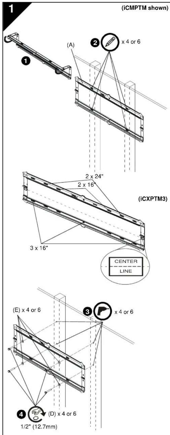
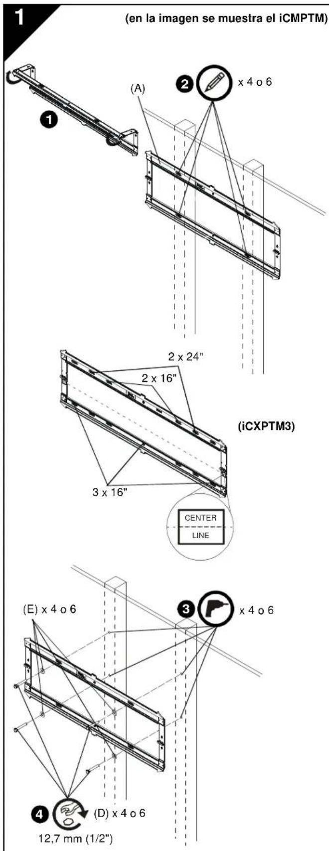
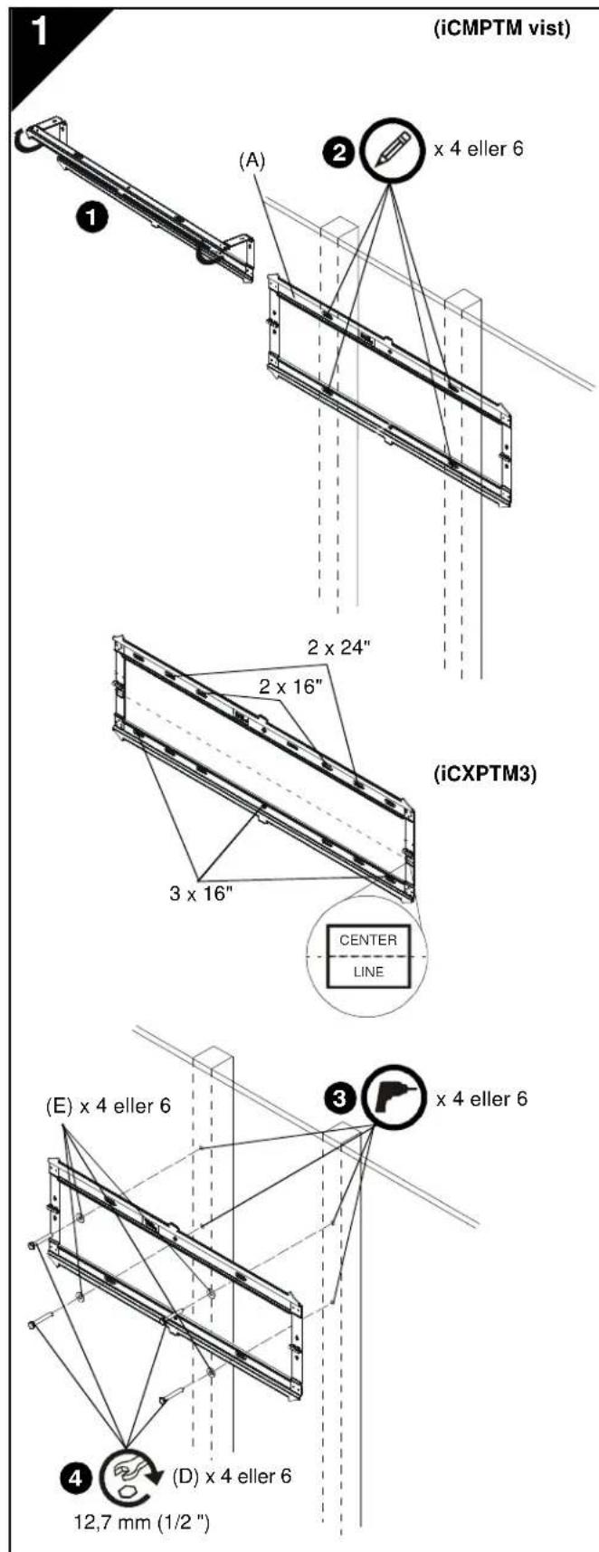
INSTALL WALL PLATE TO WALL - WOOD STUDS

WARNING: Failure to provide adequate structural strength for this component can result in serious personal injury or damage to equipment! It is the installer's responsibility to make sure the structure to which this component is attached can support five times the combined weight of all equipment. Reinforce the structure as required before installing the component. The wall to which the mount is being attached may have a maximum drywall thickness of 5/8'' (1.6cm).
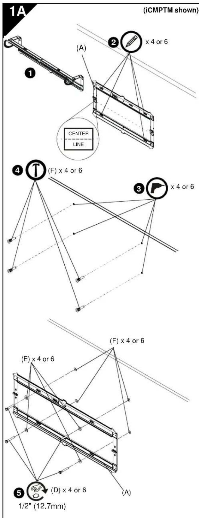
- Unfold wall plate (A) to prepare it for mounting to wall.
- Level wall plate (A) and mark locations of pilot holes.
NOTE: The iCMPTM3 must be installed on two 16" studs. The iCLPTM3 can be installed on 16" studs (inner holes) or 24" studs (outer holes). For the iCXPTM3, it can be mounted over two or three 16" studs or two 24" studs. If mounting to three 16" studs, it must be mounted to all three studs using the outer holes and center holes.
NOTE: The vertical center of the display will be even with the center line indicated on the labels located directly below each hinge. Keep this in mind when determining mounting location.
- Drill 7 / 32^ (5.5mm) diameter pilot holes into wood studs.
- Using 1/2'' (12.7mm) wrench, install screws (D) through flat washers (E), wall plate (A) and into wood studs.
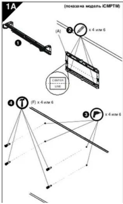
INSTALL WALL PLATE TO WALL - CONCRETE, CONCRETE BLOCK OR BRICK
WARNING: Failure to provide adequate structural strength for this component can result in serious personal injury or damage to equipment! It is the installer's responsibility to make sure the structure to which this component is attached can support five times the combined weight of all equipment. Reinforce the structure as required before installing the component.
WARNING: ELECTRICAL SHOCK HAZARD! CUTTING OR DRILLING INTO ELECTRICAL CORDS OR CABLES CAN CAUSE DEATH OR SERIOUS PERSONAL INJURY! ALWAYS make certain area behind mounting surface is free of electrical wires and cables before drilling or installing fasteners.
WARNING: EXPLOSION AND FIRE HAZARD! CUTTING OR DRILLING INTO GAS PLUMBING CAN CAUSE DEATH OR SERIOUS PERSONAL INJURY! ALWAYS make certain area behind mounting surface is free of gas, water, waste, or any other plumbing before cutting, drilling, or installing fasteners.
- Unfold wall plate (A) to prepare it for mounting to wall.
- Level wall plate (A) and mark locations of pilot holes at desired mounting location.
NOTE: For the iCLPTM3, either the inner or outer four holes may be used.
NOTE: For the iCXPTM3, use the outer four holes and the two middle holes on wall plate for installation.
NOTE: The vertical center of the display will be even with the center line indicated on the labels located directly below each hinge. Keep this in mind when determining mounting location.
- Drill 5/16" (7.9mm) diameter pilot holes into wall at marked locations. Holes must be drilled at least 2-1/2 inches deep.
- Install concrete anchors (F) into drilled holes. Use a hammer to tap anchors into holes.
- Using 1 / 2'' (12.7mm) wrench, install screws (D) through flat washers (E), wall plate (A) and into concrete anchors (F).
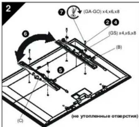
INSTALL BRACKETS TO DISPLAY

WARNING: The minimum hole pattern size is 100mm× 100mm for the iCMPTM3 and 200mm× 200mm for the iCLPTM3 and the iCXPTM3.
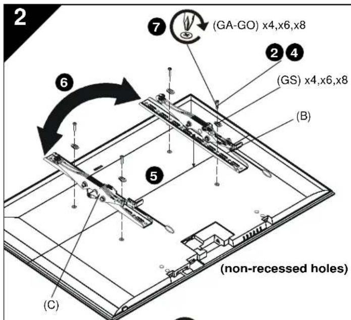
- Lay display face down on protective surface.

CAUTION: Using screws of improper diameter may damage your display! Proper screws will easily thread into display mounting holes.
-
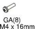
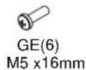
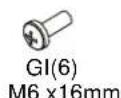
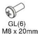
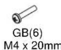
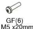
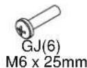
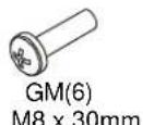
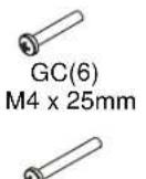
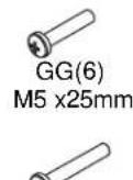
Select screw diameter by examining hardware (GA-GO) (8mm, 6mm, 5mm, or 4mm) and comparing with mounting holes on display.
-
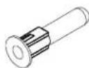
Select spacers:
-
If mounting holes are not recessed and both brackets (B and C) can lay flat against display, then no spacers are required.
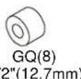
If mounting holes are recessed, or if protrusions prevent brackets (B and C) from laying flat, then spacers (GP or GQ) must be used.

CAUTION: Using screws of improper length may damage your display! Proper screws will have adequate thread engagement without contacting bottom of display mounting holes.
-
Select screw length:
-
Using your hand, insert SHORTEST length screw of selected diameter (GA, GE, GI or GL) through brackets (B and C), universal washer (GS), selected spacer (GP or GQ, if required), into display mounting hole. Do NOT thread screw into hole at this time.
-
Proper screw length requires base of screw head to protrude above flat washer a distance equal to or greater than the screw diameter. If screw length is inadequate, select longer screw. Select shortest screw which will protrude the required distance.
-
Place brackets (B and C) on display, ensuring:
Upper hooks are towards top of display.
- Center of brackets (B and C) are as close to the center of the back of display as possible after being installed. Center of bracket is indicated by the diamond-shaped hole.
- If installing display with wide hole pattern, it may be necessary to swap the uprights (B and C). See Switching Interface Brackets section for details.
- Using Phillips screwdriver, carefully install selected screws through universal washers (GS), brackets (B and C), and spacers (GP or GQ, if required), into display.
- Tighten all screws. Ensure all applicable display mounting holes (4, 6, or 8) are used.
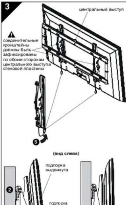
INSTALL DISPLAY TO WALL PLATE

WARNING: Exceeding the weight capacity can result in serious personal injury or damage to equipment! It is the installer's responsibility to make sure the combined weight of all components attached does not exceed 125 lbs (56.7 kg) for the iCMPTM3 and iCLPTM3 or 175 lbs (79.4 kg) for the iCXPTM3. Use with products heavier than the maximum weight indicated may result in collapse of the mount and its accessories causing possible injury.

WARNING: Display may be very heavy! Ensure display can be safely lifted and maneuvered as required to install on wall plate. Failure to take adequate precautions can result in serious personal injury or damage to equipment!

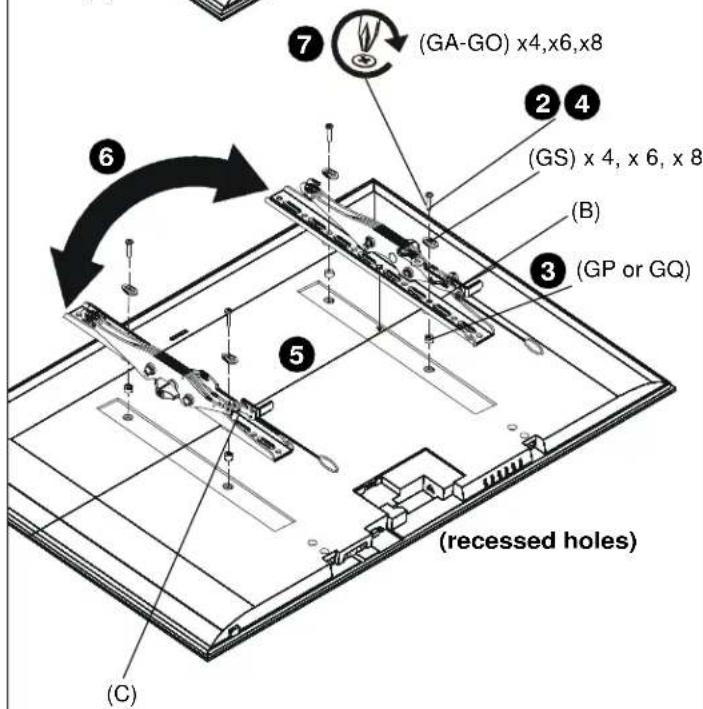
WARNING: Interface brackets must be hung on opposite sides of the center tab on wall plate!
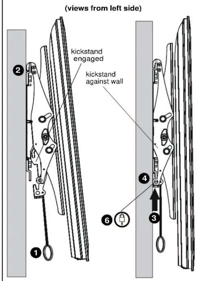
- Make sure interface brackets are in the kickstand position by pulling down on handles as far as possible.
- Hang display with brackets (B and C) on upper rail of wall plate (A). Kickstand should be engaged with lower portion of wall plate.
NOTE: Any cable management or rear display adjustments should be made when the display is resting on the kickstand.
- Unlock kickstand by pushing up on interface brackets until kickstand rests against the wall.
- Push up on the interface brackets further in order to lock display into position against wall.
- Straps can be tucked behind display on notch on interface brackets (B and C) after installation is complete so that they will not be visible to the viewer.
- (Optional) Route padlock or cable lock (not included) through bottom holes on interface bracket to provide additional security.
4
Switching Interface Brackets (Optional)
For wide hole patterns, interface brackets must be reversed. See Table 1 below to determine if this is necessary.
Table 1: Hole Pattern Width
| Model # | normal installation swap uprights | |
| iCMPTM3 100-44 | 0mm 441-506mm | |
| iCLPTM3 200-66 | 3mm 664-728.8mm | |
| iCXPTM3 200-84 | 7mm 848-913mm | |
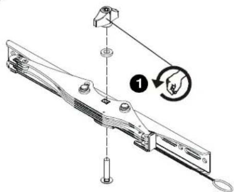
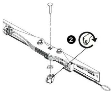
- Remove the tilt tension knob, washer and screw from interface bracket.
IMPORTANT ! : Hold the brackets steady when removing the knob, washer and screw from interface bracket to prevent internal washers from falling out. If internal washers do fall out, they must be reinserted in proper position before reinstalling knob on the other side! - Replace the knob, washer and screw in the opposite order.
- Repeat for the other interface bracket.
- Install interface brackets according to instructions in Section 2.
5
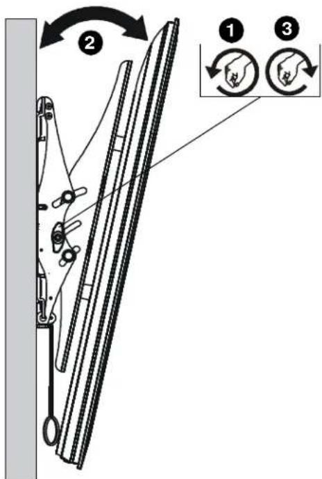
Tilt Adjustment
- Adjust tilt tension adjustment knobs to desired tension.
- Adjust tilt of display by pulling the top of display away from the wall until desired tilt position is reached.
- Tighten tilt tension adjustment knobs to secure tilt position.
INSTALLACION DE LA PLACA DE PARED EN LA PARED: MONTANTES DE MADERA

INSTALLLEER HET SCHERM AAN DE WANDPLAAT

K P E N I E H M E C T E H O B O I N L A C T M H B I K C T E H - D E P E B R H H A K P K A C H A C T E H A
PNDYNPKEKDEHNE. HeoCTaONHn npOHcBt MATEpNANA CTHeB B MCECT XePNENHn DAHNHO DetaH NMOKET pNBEcTHX KOpE3Hb TM PABMn HNOpezHEHNOO OOBpyOaBHNI FIIO, BUNHOHNOy EYCTAOHbky. 083AHO y6DBeTBCB TOM, YTO npOHOCTb MATEpNANA CTHeB M CECT XePNENHn DAHNHO DetaTm NOBcHReR BbEPKbTB HAPKyHO, PNEoCXQdYHO B nTb PA3 BEC BOERHO MEOUcRO OBOPdyOBHn. Pn HEOxPMOCHN NEpeyCYTAHOBKn DAHNHO DetAHn CNeDeYnpNHPRE MeBPOI dNBOuHEHn npOHcTHN MATEpNANA CTHeB. ToOnHHa uTyKATPKn HA CTHe, KKTOpO npEnerTO KPOHUsHbN, DOxNkCoCTAnrBbHbE Bo9ne1.5 cm
- Pasebephite ctehoBky nactnHy (A) dnr noqrotoaK KMOCTAKy HA CTeyH.
- BupohBnHRe nAChy (A) ANMTERM EMeTOnONOXENHE HANPAIINHOX OTEPCTN
IINPIMEHAHNE. MoenbICMPTMDpKna yctaHaanBaTCn ha CTNOH 40.6 CM.MoEnbCLPTM3MQeT yctaHaanBaTnHa h CTNOH 40.6 CM (BHTpyrHeN OABpcTHN) nnn 61.0 CM (HApynHeO bTBePCTN). MoenbICXPMTM3MQeT yctaHaanBaTnHa h Da Ie mtn TPO CTNOH DnHOH 40.6 CM INH DE CTNOH dHHoH 61.0 CM.PnpyTcAnKe h TPO CTNOH DnHOH 40.6 CM BTE pTO CHIO H DOTHHO KPNHbB AHPyKHNX n eDHTPAHbNbOTBePCTWk
PIMMEAHHE. CepdinaKkaHnO noBertikamB 6yD 0eAaBdtcC HteTAPNHOHmH
KPENJIHNE CTEHOBOI NACTINHBI KCTHE -BETOH, BETOHHbIE BLOKINIM KMPN
I PEPDYPPEKDEHEH. HepoCTOCHRA pOHOCTB MATEPHANCTEHMB MECTE KPNENHNDAHNO DETAM MOKET PNEBECTN C OEBPENHUM TPAHMM NPOPEKDAHNO OBOpyDAHNI IIO, BAOHINKOTSEY cTAAHO, OBOAHO 8ypeBdA TO ATO YPO NOHOCMATEPHANCTC HbM B MCEKT PKNENHNDAHNO DETAM NOBONNET BueQePKATB HAPyDy, PpEOXDOHUYO a NRTA PaeB EGORE NMOUEROS OBOpyDAHNI. PnH eOeKIMOCNT NepeR yCTAHOBK DAnHDM DcFeyr pNnHTB MPBnD nIPOBHeH NPOHOCTN MATEPHANCTC HbN
PNEpyPKEKDEHME:ONACHCTbNOPAKEHNI 3IIEKTPYNCKVAMTKOMPAS3PEAHHEINI PPOCBEPINBAHME NPOBDAINIKABELIMOKET PNYBECTNXCEPBESHIMTPABMMINEM CMEPTEBHOYMVCXQDITpeCbpENHNO tOeTcHnYyctAHOHOR pEeKoHxAaHemTo8 O5R3ATeHbHOyDeBtceAtcm,TOBaeMeTe yctAHoHKe HET AIOeHNKcXpnoDBOsNkAEHn.
IPEDYNPPEKDEHNE:ONACHOCTB83PbBAWIMIOKAPA1PA3E3AHHEIMIPOCBEPYVBAHIVERAOBOITPyblMOKETNPVBECTNCKEPB3HBMTPABMMIIMCMEPTeBHOMHYOXODIYPedexh,cpeHemMeOBtepnIyckTahayohkpenekeshanmeHnoOB3ATEBHOy6dApTeBcTOM.4TOA BmteyctaHOHHTaHOx,bOopnpoBdoHxKaHANALAMOHNOHNJyDpyTp6
- PasebnHite TchnoBko pIaChnky (A) An noTroBko KMOeHaKy HA CTsHcy
- BapoeHBeI nactVy (A) 0mTeTe MecToOnoNMeHe HnpaanBnauXg ToaepCTb A hynbHex MeTAX. PPMEYAHHE, INR MODER ICLPTM3MOKHO
YCTAHOBITE KPOHHTENHBI HA MOHITOP

PINEPYNEKDEHNE. MMHHMAMAHOO PACBOCHHO MENyD BYOTBPCHTMOO CCAOCTNHO 100MMX100MM DUN MOEINI cOMPMTM3X200MMX200MM INI dMQEMN ICLPTM3WICXPTM3.
1.ПОТКЕТМОНТРЗКOMБИНHAнрдбхангсукоу
<|im_start|>assistant
ФОТКЕТМОНТРЗКOMБИНHAнрдбхангсукоу

BHIMAHME, INoIaOaMaBaHBe HnEOeTOBCTAYouEe duAMERpa MOeR napeBdTe MoHIOrP BHTbCoAeTOBCTAYouEe duAMERpa IeNo bkyAOTBmB aMOKtAEoTEp39.
2.Плобергду AmalopBHTA.NOOKPepDHO BHMMAH KENKEX3PAXETOB(GA-GG)8MM,5MM 4mm)HHCpBBMBAHROCMOHTAHMHN OTBEPCHM H3 MOHOTPO
3. No6epure atynr.
ECMMOHTAKHHeOBePCTeN HeYToHNHe, 06aXPOHATEHe(BnC)noTHNO pAnmTaI MHOOTyO,TOBIVIOH HNOH
ECNMOHTAHOBOTBOPETRytONHNNH 电 电 HADKNTIOHPOHPKHOHTHBn(BxC)KOHATOPC,CHDyER MOHNOA BAYN (GP with GO).

BHMMHME, HMOAOMBAHME AHMTB HHOATOTCTAYOON DNNH MOH NMOEPTMH MOnHTOP BHTHCOOTAEYTOON DNNH BPOMABOTCHAO HA DOCTAO HOE PACCTAHME HEOXADQAMOTAKHNO OTEPMAHMTOHOP
4.
PyroBKPyrKCTMcMbI KOPOTKmHnH 6aBpAHOuDnEPA (GA,GE,GI,GNL) 1ep3KpOAnr (BnC),yNepcePbHyto 8a5y(GS),6bApHNOAty anry aTopoSy nAnh (F),6bApHNOAty (GP mNtGQ, eonr ppeyic) aOBPteCeXpnePnMe MOHnOpa. NaHe BKPY4BAITE HnTHMOHnOBPOBTEe
Ee
YCTAHOBKA MOHNTOPA HA CTEHOBYIOIJIACTHNY
NPEYNPKEKDEHE.PeBaeHHe HAPyckn NO BECy MOEETPNEBECTK CepbE3HbT PABAM NIOpeKDeHNO O6OpOaBcHbIbIb, BnOReHMeoee YcHbOkyOBaEO b6yBaTcBbA T QTO CYMMAHBC BOCxYCTAOHNHbX KOMONHOHTO He pBeauaTe 56,7 kT (125 yfHTo) dA MoeJeN cIOPMT3NcIPLTM3;79,4 kT (175 yfHTo) dA MoenN cIXPTM3. INnoNtobHe C cyptOCTaAM. BEc KOTopux npeBaeT EykAaBHe MAXOMAaHbN BEC MocetpBcTcN KOpEeDhxoKoHHTeN NpNDHApNekCtoH xNOnyHEnoTpaam.
PENYPNPEKDEHNE. MOHTOP MOKET GbTb OHHS TAKKJIIM! YBSEHTEc, YTO MOHTOP MOKET GbTe BcONACHO QNTHR INCTAHBOHN HBA CTHEBOHYI NACTHYY ECIN He PnIRHTb HEOKdMIXM MIP npEOCTOPXHOCTH, 3TO MOKET pnpEeCtK K OEPsHbTM TpaAMM INoepxDHeKO BOPOpyaHANl
IpectaHOBKa CoeHNHTeBbIX KPOHHTeHOB (DONONHTeBHaB BO3MOXHOCTb)
IINHPOKOKXCMbpaONONKEHNRcBepCTN
COeAHHTENHbKPOHHTBNHeHO6OxDMIO NMeHHTb
MECTAMHEoXoDMOCt3TOROMOxHO ONpeDnHtNo
TaNaIe1NPpeDeHNO HKe
Ta6nua1: WpHnHa cxempaacnonoxeknna 0TbePc
| Moolb | yCTBTHO4K3Ge3 CMFIMIPIIHOX | yCTBTHO4K3C O CMHNOA PONNO |
| ICMPTMO | 100-4-40mm | 441-506mm |
| ICLPTMO | 200-6-63mm | 664-728.8mm |
| ICXPTMO | 200-8-47mm | 848-913mm |
- CHIMMATE peryrnyTATOP HAIKIXHIN PPOHAXIOHE WAIyO, OTHAHNTTE AHTC 00EQHINTENbHO KPOHHTeHa.
BAXHOT! :UdpKbHaeR KPOHHeB IN KCKDHM
nONoXHHn pRCHTHpEpyrTOpA HATRAHHE
pnHAnHO, 7aBb6 bNHTaCoEHINHTENHO
KPOHHeHa, YTO6bI npDeTbPamITb BynapHe
BHyTPeHHx 7aH6. EcnH BHYTPeHHe 7aHb6
BbHNH, INX HeO6kDmHOyCTAHOBtB nPaBnHoe
nONoHXe, npEckd cHcKpEnerb pyrTOp HA
dpyro t copone!
2.YCTAHOBHTEpyNTOP,uaBbY3aBHTN8BHT(a 05PHTHOncnOeOBAOTENHOCT)
3. Noatopate Te je onepaun dnydpyrto coepHHTeBHOrO XPOHHTeHa.
4. Uctanohuite Cooghohtenbte kpoohitbe cncohao xkyahannm, npwdehenbte B Paedene 2.
Perynipobka yma haknoha
MONTERING AF VEGPLADE PÄ VEG - TRÉ TAPSKRUER

USA·8401 Eagle Creek Parkway, Suite 700·Savage, Minnesota 55378·800.572.1373
EMEA·+31(0)402668620
www.icmounts.com
©2010 Milestone AV Technologies. The iC Logo and StowAway are trademarks of Chief Manufacturing,
a products division of Milestone AV Technologies, a Duchossois Group Company. All rights reserved
Patents and patents pending. Milestone AV Technologies, Savage, MN 55378, USA 8800-002041 Rev 01
02/10