USER MANUAL Fatal1ty Z87 Killer ASROCK
Published September 2013
Copyright ©2013 ASRock INC. All rights reserved.
Copyright Notice:

No part of this documentation may be reproduced, transcribed, transmitted, or translated in any language, in any form or by any means, except duplication of documentation by the purchaser for backup purpose, without written consent of ASRock Inc.
Products and corporate names appearing in this documentation may or may not be registered trademarks or copyrights of their respective companies, and are used only for identification or explanation and to the owners' benefit, without intent to infringe.
Disclaimer:
Specifications and information contained in this documentation are furnished for informational use only and subject to change without notice, and should not be constructed as a commitment by ASRock. ASRock assumes no responsibility for any errors or omissions that may appear in this documentation.
With respect to the contents of this documentation, ASRock does not provide warranty of any kind, either expressed or implied, including but not limited to the implied warranties or conditions of merchantability or fitness for a particular purpose.
In no event shall ASRock, its directors, officers, employees, or agents be liable for any indirect, special, incidental, or consequential damages (including damages for loss of profits, loss of business, loss of data, interruption of business and the like), even if ASRock has been advised of the possibility of such damages arising from any defect or error in the documentation or product.

This device complies with Part 15 of the FCC Rules. Operation is subject to the following two conditions:
(1) this device may not cause harmful interference, and
(2) this device must accept any interference received, including interference that may cause undesired operation.
CALIFORNIA, USA ONLY
The Lithium battery adopted on this motherboard contains Perchlorate, a toxic substance controlled in Perchlorate Best Management Practices (BMP) regulations passed by the California Legislature. When you discard the Lithium battery in California, USA, please follow the related regulations in advance.
"Perchlorate Material-special handling may apply, see www.dtsc.ca.gov/hazardouswaste/perchlorate"
ASRock Website: http://www.asrock.com
The terms HDMI and HDMI High-Definition Multimedia Interface, and the HDMI logo are trademarks or registered trademarks of HDMI Licensing LLC in the United States and other countries.

Manufactured under license under U.S. Patent Nos: 5,956,674; 5,974,380; 6,487,535; 7,003,467 & other U.S. and worldwide patents issued & pending. DTS, the Symbol, & DTS and the Symbol together is a registered trademark & DTS Connect, DTS Interactive, DTS Neo:PC are trademarks of DTS, Inc. Product includes software.
DTS, Inc., All Rights Reserved.

Connect


Interactive


Neo:PC
Who knew that at age 19, I would be a World Champion PC gamer. When I was 13, I actually played competitive billiards in professional tournaments and won four or five games off guys who played at the highest level. I actually thought of making a career of it, but at that young age situations change rapidly. Because I've been blessed with great hand-eye coordination and a grasp of mathematics (an important element in video gaming) I gravitated to that activity.
GOING PRO
I started professional gaming in 1999 when I entered the CPL (Cyberathlete Professional League) tournament in Dallas and won 4,000 for coming in third place. Emerging as one of the top players in the United States, a company interested in sponsoring me flew me to Sweden to compete against the top 12 players in the world. I won 18 straight games, lost none, and took first place, becoming the number one ranked Quake III player in the world in the process. Two months later I followed that success by traveling to Dallas and defending my title as the world's best Quake III player, winning the40,000 grand prize. From there I entered competitions all over the world, including Singapore, Korea, Germany, Australia, Holland and Brazil in addition to Los Angeles, New York and St. Louis.
WINNING STREAK
I was excited to showcase my true gaming skills when defending my title as CPL Champion of the year at the CPL Winter 2001 because I would be competing in a totally different first person shooter (fps) game, Alien vs. Predator II. I won that competition and walked away with a new car. The next year I won the same title playing Unreal Tournament 2003, becoming the only three-time CPL champion of the year. And I did it playing a different game each year, something no one else has ever done and a feat of which I am extremely proud.
At QuakeCon 2002, I faced off against my rival ZeRo4 in one of the most highly anticipated matches of the year, winning in a 14 to (-1) killer victory. Competing at Quakecon 2004, I became the World's 1st Doom3 Champion by defeating Daler in a series of very challenging matches and earning $25,000 for the victory.
Since then Fatality has traveled the globe to compete against the best in the world, winning prizes and acclaim, including the 2005 CPL World Tour Championship in New York City for a $150,000 first place triumph. In August 2007, Johnathan was awarded the first ever Lifetime Achievement Award in the four year history of the eSports-Award for "showing exceptional sportsmanship, taking part in shaping eSports into what it is today and for being the prime representative of this young sport. He has become the figurehead for eSports worldwide".
LIVIN' LARGE
Since my first big tournament wins, I have been a "Professional Cyberathlete", traveling the world and livin' large with lots of International media coverage on outlets such as MTV, ESPN and a 60 Minutes segment on CBS to name only a few. It's unreal - it's crazy. I'm living a dream by playing video games for a living. I've always been athletic and took sports like hockey and football very seriously, working out and training hard. This discipline helps me become a better gamer and my drive to be the best has opened the doors necessary to become a professional.
ADREAM
Now, another dream is being realized - building the ultimate gaming computer, made up of the best parts under my own brand. Quality hardware makes a huge difference in competitions...a couple more frames per second and everything gets really nice. It's all about getting the computer processing faster and allowing more fluid movement around the maps.
My vision for Fatality hardware is to allow gamers to focus on the game without worrying about their equipment, something I've preached since I began competing. I don't want to worry about my equipment. I want to be there - over and done with - so I can focus on the game. I want it to be the fastest and most stable computer equipment on the face of the planet, so quality is what Fatality Brand products represent.

Johnathan "Fatality" Wendel

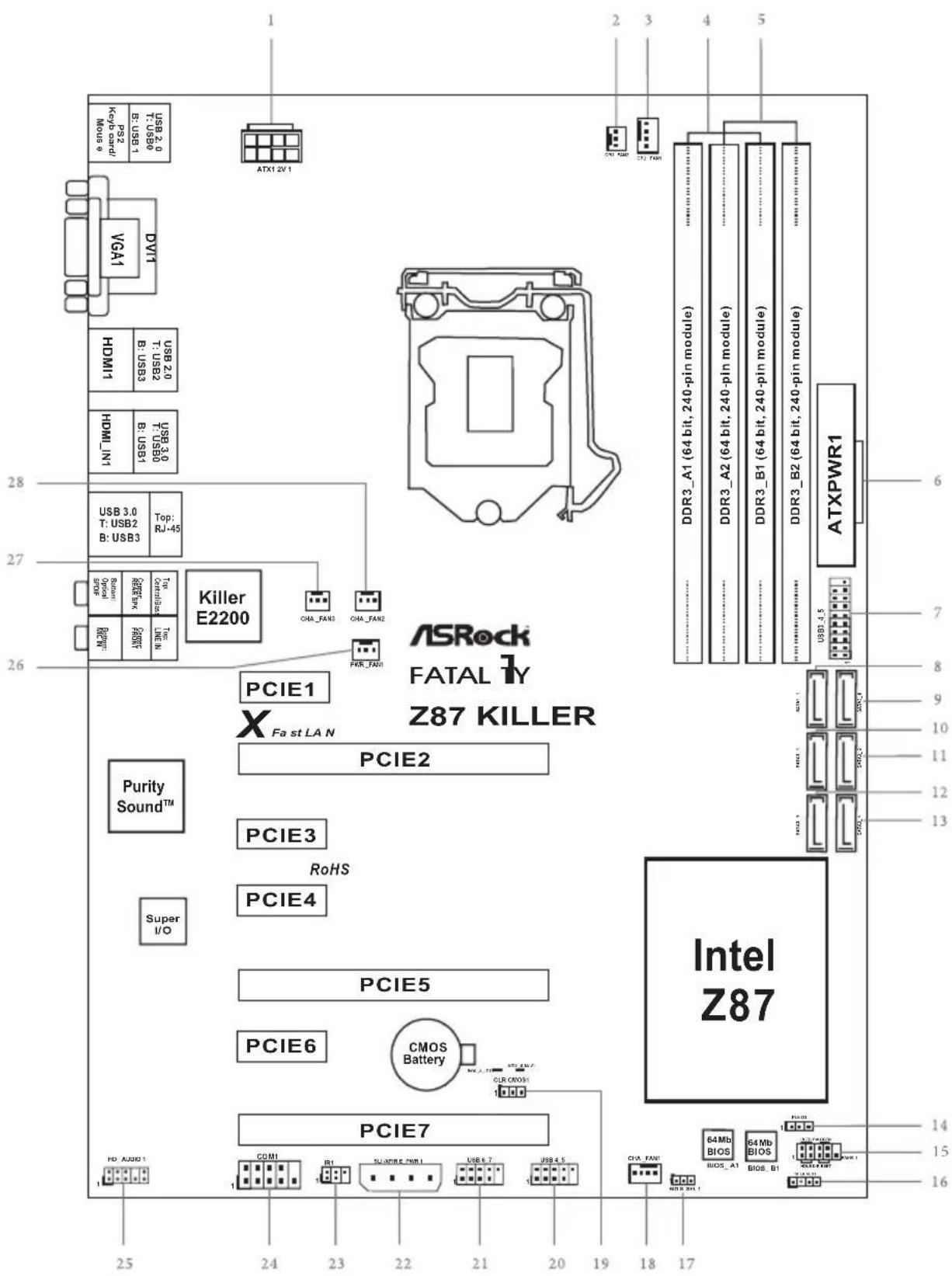
Motherboard Layout
No.Description
1ATX 12V Power Connector (ATX12V1)
2 CPU Fan Connector (CPU_FAN2)
3 CPU Fan Connector (CPU_FAN1)
4 2 x 240-pin DDR3 DIMM Slots (DDR3_A1, DDR3_B1)
5 2 x 240-pin DDR3 DIMM Slots (DDR3_A2, DDR3_B2)
6 ATX Power Connector (ATXPWR1)
7 USB 3.0 Header (USB3_4_5)
8 SATA3 Connector (SATA3_1)
9 SATA3 Connector (SATA3_0)
10 SATA3 Connector (SATA3_3)
11 SATA3 Connector (SATA3_2)
12 SATA3 Connector (SATA3_5)
13 SATA3 Connector (SATA3_4)
14 Power LED Header (PLED1)
15 System Panel Header (PANEL1)
16 Chassis Speaker Header (SPEAKER1)
17 BIOS Selection Jumper (BIOS_SEL1)
18 Chassis Fan Connector (CHA_FAN1)
19 Clear CMOS Jumper (CLRCMOS1)
20 USB 2.0 Header (USB4_5)
21 USB 2.0 Header (USB6_7)
22 SLI/XFIRE Power Connector (SLI/XFIRE_PWR1)
23 Infrared Module Header (IR1)
24 COM Port Header (COM1)
25 Front Panel Audio Header (HD AUDIO01)
26 Power Fan Connector (PWR_FAN1)
27 Chassis Fan Connector (CHA_FAN3)
28 Chassis Fan Connector (CHA_FAN2)
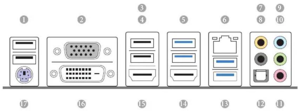
I/O Panel
No. Description No. Description
1 USB 2.0 Ports (USB01) 10 Front Speaker (Lime)*
2 D-Sub Port 11 Microphone (Pink)
3 Fatal1ty Mouse Port (USB2) 12 Optical SPDIF Out Port
4 USB 2.0 Port (USB3) 13 USB 3.0 Ports (USB3_23)
5 USB 3.0 Ports (USB3_01) 14 HDMI-In Port
6 LAN RJ-45 Port 15 HDMI-Out Port
7 Central / Bass (Orange) 16 DVI-D Port
8 Rear Speaker (Black)
17 PS/2 Mouse/Keyboard Port
9 Line In (Light Blue)
- There are two LEDs on each LAN port. Please refer to the table below for the LAN port LED indications.
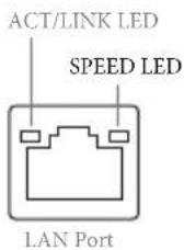
| Activity / Link LED Speed LED | |
| Status Description Status Description | |
| Off No Link Off | 10Mbps connection | | |
| Blinking Data Activity Orange 100Mbps | connection | |
| On Link Green | 1Gbps connection | | |
** If you use a 2-channel speaker, please connect the speaker's plug into "Front Speaker Jack". See the table below for connection details in accordance with the type of speaker you use.
| Audio Output Channels | Front Speaker (No. 10) | Rear Speaker (No. 8) | Central / Bass (No. 7) | Line In (No. 9) |
| 2 V -- -- | | | | |
| 4 V V -- | | | | |
| 6 V V V -- | | | | |
| 8 V V V V | | | | |

To enable Multi-Streaming, you need to connect a front panel audio cable to the front panel audio header. After restarting your computer, you will find the "Mixer" tool on your system. Please select "Mixer ToolBox" click "Enable playback multi-streaming", and click "ok". Choose "2CH", "4CH", "6CH", or "8CH" and then you are allowed to select "Realtek HDA Primary output" to use the Rear Speaker, Central/ Bass, and Front Speaker, or select "Realtek HDA Audio 2nd output" to use the front panel audio.
Chapter 1 Introduction
Thank you for purchasing ASRock Fatality Z87 Killer Series motherboard, a reliable motherboard produced under ASRock's consistently stringent quality control. It delivers excellent performance with robust design conforming to ASRock's commitment to quality and endurance.

Because the motherboard specifications and the BIOS software might be updated, the content of this manual will be subject to change without notice. In case any modifications of this manual occur, the updated version will be available on ASRock's website without further notice. If you require technical support related to this motherboard, please visit our website for specific information about the model you are using. You may find the latest VGA cards and CPU support list on ASRock's website as well. ASRock website http://www.asrock.com.
1.1 Package Contents
ASRock Fatality Z87 Killer Series Motherboard (ATX Form Factor)
ASRock Fatality Z87 Killer Series Quick Installation Guide
ASRock Fatality Z87 Killer Series Support CD
- 4 x Serial ATA (SATA) Data Cables (Optional)
- 1 x I/O Panel Shield
- 1 x ASRock SLI_Bridge_2S Card
1.2 Specifications
| Platform | • ATX Form Factor
• Premium Gold Capacitor design (100% Japan-made high-quality conductive polymer capacitors) |
| A-Style | • Purity SoundTM
• HDMI-In |
| Gaming Armor | CPU Power
• Hi-Density Power Connector
VGA Card
• 15μGold Finger in VGA PCIe Slot (PCIE2)
• SLI/CrossFireX Power Connector
Internet
• Qualcomm® Atheros® KillerTM LAN
Audio
• Purity SoundTM |
| CPU | • Supports 4thgeneration Intel® CoreTM i7 / i5 / i3 / Xeon® / Pentium® / Celeron® in LGA1150 package
• Digi Power design
• 8 Power Phase design
• Supports Intel® Turbo Boost 2.0 Technology
• Supports Intel® K-Series unlocked CPUs
• Supports ASRock BCLK Full-range Overclocking |
| Chipset | • Intel® Z87 |
| Memory | • Dual Channel DDR3 Memory Technology
• 4 x DDR3 DIMM Slots
• Supports DDR3 3050+(OC)/2800(OC)/2400(OC)/2133 (OC)/1866 (OC)/1600/1333/1066 non-ECC, un-buffered memory
• Max. capacity of system memory: 32GB (see CAUTION)
• Supports Intel® Extreme Memory Profile (XMP)1.3/1.2 |
Expansion Slot
- 3 x PCI Express 3.0 x16 Slots (PCIE2/PCIE5/PCIE7: single at x16 (PCIE2); dual at x8 (PCIE2) / x8 (PCIE5); triple at x8 (PCIE2) / x4 (PCIE5) / x4 (PCIE7))
- 4 x PCI Express 2.0 x1 Slots
Supports AMD Quad CrossFireXTM, 3-Way CrossFireXTM and CrossFireXTM
Supports NVIDIA® Quad SLI™ and SLI™
Graphics
Intel® HD Graphics Built-in Visuals and the VGA outputs can be supported only with processors which are GPU integrated
Supports Intel® HD Graphics Built-in Visuals : Intel® Quick Sync Video with AVC, MVC (S3D) and MPEG-2 Full HW Encode1, Intel® InTru™ 3D, Intel® Clear Video HD Technology, Intel® Insider™, Intel® HD Graphics 4600
Pixel Shader 5.0, DirectX 11.1
Max. shared memory 1792MB
- Three VGA Output options: D-Sub, DVI-D and HDMI Port
Supports Triple Monitor
Supports HDMI Technology with max. resolution up to 4K× 2K (4096x2304) @ 24Hz
Supports DVI-D with max. resolution up to 1920x1200 @ 60Hz
Supports D-Sub with max. resolution up to 1920x1200 @ 60Hz
Supports Auto Lip Sync, Deep Color (12bpc), xvYCC and HBR (High Bit Rate Audio) with HDMI Port (Compliant HDMI monitor is required)
Supports HDCP with DVI-D and HDMI Ports
Supports Full HD 1080p Blu-ray (BD) playback with DVI-D and HDMI Ports
Audio
7.1 CH HD Audio with Content Protection (Realtek ALC1150 Audio Codec)
- Premium Blu-ray Audio Support
Supports Purity SoundTM -115dB SNR DAC with Differential Amplifier
- TI® NE5532 Premium Headset Amplifier (Supports up to 600 ohm headsets)
- Direct Drive Technology
- EMI Shielding Cover
-PCB Isolate Shielding
Supports DTS Connect
LAN
PCIE x1 Gigabit LAN 10/100/1000 Mb/s
Qualcomm® Atheros® Killer™ E2200 Series
Supports Wake-On-LAN
Supports Energy Efficient Ethernet 802.3az
Supports PXE
Rear Panel I/O
- 1 x PS/2 Mouse/Keyboard Port
- 1 x D-Sub Port
- 1xDVI-D Port
- 1 x HDMI-Out Port
- 1 x HDMI-In Port
1 x Optical SPDIF Out Port
- 3xUSB2.0Ports
- 1 x Fatality Mouse Port (USB 2.0)
- 4xUSB3.0Ports
- 1 x RJ-45 LAN Port with LED (ACT/LINK LED and SPEED LED)
- HD Audio Jacks: Rear Speaker / Central / Bass / Line in / Front Speaker / Microphone
Storage
- 6 x SATA3 6.0 Gb/s Connectors, support RAID (RAID 0, RAID 1, RAID 5, RAID 10, Intel Rapid Storage Technology 12 and Intel Smart Response Technology), NCQ, AHCI and Hot Plug
Connector
- 1 x IR Header
- 1x COM Port Header
- 1xPowerLEDHeader
- 2 x CPU Fan Connectors (1 x 4-pin, 1 x 3-pin)
- 3 x Chassis Fan Connectors (1 x 4-pin, 2 x 3-pin)
- 1 x Power Fan Connector (3-pin)
- 1 x 24 pin ATX Power Connector
- 1 x 8 pin 12V Power Connector (Hi-Density Power Connector)
| • 1 x SLI/XFire Power Connector
• 1 x Front Panel Audio Connector
• 2 x USB 2.0 Headers (Support 4 USB 2.0 ports)
• 1 x USB 3.0 Header (Supports 2 USB 3.0 ports) |
| BIOS Feature | • 2 x 64Mb AMI UEFI Legal BIOS with multilingual GUI support (1 x Main BIOS and 1 x Backup BIOS)
• Supports Secure Backup UEFI Technology
• ACPI 1.1 Compliant wake up events
• SMBIOS 2.3.1 support
• CPU, DRAM, PCH 1.05V, PCH 1.5V Voltage multi-adjust-ment |
| Support CD | • Drivers, Utilities, AntiVirus Software (Trial Version), Google Chrome Browser and Toolbar, Start8 (30 days trial), XSplit, Killer Network Manager |
| Hardware Monitor | • CPU/Chassis temperature sensing
• CPU/Chassis/Power Fan Tachometer
• CPU/Chassis Quiet Fan (Auto adjust fan speed by CPU temperature)
• CPU/Chassis Fan multi-speed control
• Voltage monitoring: +12V, +5V, +3.3V, CPU Vcore Voltage |
| OS | • Microsoft* Windows* 10 64-bit / 8.1 32-bit / 8.1 64-bit / 8 32-bit / 8 64-bit / 7 32-bit / 7 64-bit |
| Certifications | • FCC, CE, WHQL
• ErP/EuP ready (ErP/EuP ready power supply is required) |

Please realize that there is a certain risk involved with overclocking, including adjusting the setting in the BIOS, applying Untied Overclocking Technology, or using third-party overclocking tools. Overclocking may affect your system's stability, or even cause damage to the components and devices of your system. It should be done at your own risk and expense. We are not responsible for possible damage caused by overclocking.

Due to limitation, the actual memory size may be less than 4GB for the reservation for system usage under Windows® 32-bit operating systems. Windows® 64-bit operating systems do not have such limitations. You can use ASRock XFast RAM to utilize the memory that Windows* cannot use.
1.3 Unique Features

ASRock F-Stream
F-Stream is ASRock's multi purpose software suite with a new interface, more new features and improved utilities, including XFast RAM, Dehumidifier, Good Night LED, FAN-Tastic Tuning, OC Tweaker and a whole lot more.

ASRock Instant Flash
ASRock Instant Flash is a BIOS flash utility embedded in Flash ROM. This convenient BIOS update tool allows you to update the system BIOS in a few clicks without preparing an additional floppy diskette or other complicated flash utility. Just save the new BIOS file to your USB storage and launch this tool by pressing <F6> or <F2> during POST to enter the BIOS setup menu to access ASRock Instant Flash. Please be noted that the USB flash drive or hard drive must use FAT32/16/12 file system.

ASRock APP Charger
Simply by installing the ASRock APP Charger makes your iPhone/iPad/iPod Touch charge up to 40% faster than before on your computer. ASRock APP Charger allows you to quickly charge many Apple devices simultaneously and even supports continuous charging when your PC enters into Standby mode (S1), Suspend to RAM (S3), hibernation mode (S4) or power off (S5).

ASRock XFast USB
ASRock XFast USB can boost the performance of your USB storage devices. The performance may depend on the properties of the device.

ASRock XFast RAM
ASRock XFast RAM is included in F-Stream. It fully utilizes the memory space that cannot be used under Windows® 32-bit operating systems. ASRock XFast RAM shortens the loading time of previously visited websites, making web surfing faster than ever. And it also boosts the speed of Adobe Photoshop 5 times faster. Another advantage of ASRock XFast RAM is that it reduces the frequency of accessing your SSDs or HDDs in order to extend their lifespan.

ASRock Crashless BIOS
ASRock Crashless BIOS allows users to update their BIOS without fear of failing. If power loss occurs during the BIOS updating process, ASRock Crashless BIOS will automatically finish the BIOS update procedure after regaining power. Please note that BIOS files need to be placed in the root directory of your USB disk. Only USB 2.0 ports support this feature.

ASRock OMG (Online Management Guard)
Administrators are able to establish an internet curfew or restrict internet access at specified times via OMG. You may schedule the starting and ending hours of internet access granted to other users. In order to prevent users from bypassing OMG, guest accounts without permission to modify the system time are required.

ASRock Internet Flash
ASRock Internet Flash downloads and updates the latest UEFI firmware version from our servers for you without entering Windows OS. Please setup network configuration before using Internet Flash.

ASRock UEFI System Browser
ASRock System Browser shows the overview of your current PC and the devices connected.

ASRock Dehumidifier Function
Users may prevent motherboard damages due to dampness by enabling "Dehumidifier Function". When enabling Dehumidifier Function, the computer will power on automatically to dehumidify the system after entering S4/S5 state.

ASRock Easy RAID Installer
ASRock Easy RAID Installer can help you to copy the RAID driver from the support CD to your USB storage device. After copying the RAID driver to your USB storage device, please change "SATA Mode" to "RAID", then you can start installing the OS in RAID mode.

ASRock Easy Driver Installer
For users that don't have an optical disk drive to install the drivers from our support CD, Easy Driver Installer is a handy tool in the UEFI that installs the LAN driver to your system via an USB storage device, then downloads and installs the other required drivers automatically.

ASRock Interactive UEFI
ASRock Interactive UEFI is a blend of system configuration tools, cool sound effects and stunning visuals. The unprecedented UEFI provides a more attractive interface and more amusement.

ASRock Fast Boot
With ASRock's exclusive Fast Boot technology, it takes less than 1.5 seconds to logon to Windows 8 from a cold boot. No more waiting! The speedy boot will completely change your user experience and behavior.

ASRock Restart to UEFI
Windows® 8 brings the ultimate boot up experience. The lightning boot up speed makes it hard to access the UEFI setup. ASRock Restart to UEFI allows users to enter the UEFI automatically when turning on the PC. By enabling this function, the PC will enter the UEFI directly after you restart.

ASRock USB Key
In a world where time is money, why waste precious time everyday typing usernames to log in to Windows? Why should we even bother memorizing those foot long passwords? Just plug in the USB Key and let your computer log in to windows automatically!
ASRock Key Master
What good is a weapon if you are unable to wield it proficiently? Key Master enhances your mouse and keyboard with customizable macros, sniper modes, scroll speed, key repeat rates and repeat delay, turning your boring old keyboard and mouse into lethal weapons.
ASRock FAN-Tastic Tuning
ASRock FAN-Tastic Tuning is included in F-Stream. Configure up to five different fan speeds using the graph. The fans will automatically shift to the next speed level when the assigned temperature is met.

ASRock Good Night LED
ASRock Good Night LED technology offers you a better sleeping environment by extinguishing the unessential LEDs. By enabling Good Night LED in the BIOS, the Power/HDD LEDs will be switched off when the system is powered on. Good Night LED will automatically switch off the Power and Keyboard LEDs when the system enters into Standby/Hibernation mode as well.
Chapter 2 Installation
This is an ATX form factor motherboard. Before you install the motherboard, study the configuration of your chassis to ensure that the motherboard fits into it.
Pre-installation Precautions
Take note of the following precautions before you install motherboard components or change any motherboard settings.
- Make sure to unplug the power cord before installing or removing the motherboard. Failure to do so may cause physical injuries to you and damages to motherboard components.
- In order to avoid damage from static electricity to the motherboard's components, NEVER place your motherboard directly on a carpet. Also remember to use a grounded wrist strap or touch a safety grounded object before you handle the components.
- Hold components by the edges and do not touch the ICs.
- Whenever you uninstall any components, place them on a grounded anti-static pad or in the bag that comes with the components.
- When placing screws to secure the motherboard to the chassis, please do not overtighten the screws! Doing so may damage the motherboard.
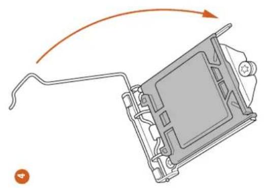
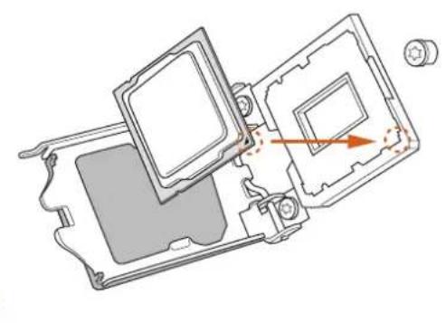
2.1 Installing the CPU

- Before you insert the 1150-Pin CPU into the socket, please check if the PnP cap is on the socket, if the CPU surface is unclean, or if there are any bent pins in the socket. Do not force to insert the CPU into the socket if above situation is found. Otherwise, the CPU will be seriously damaged.
- Unplug all power cables before installing the CPU.
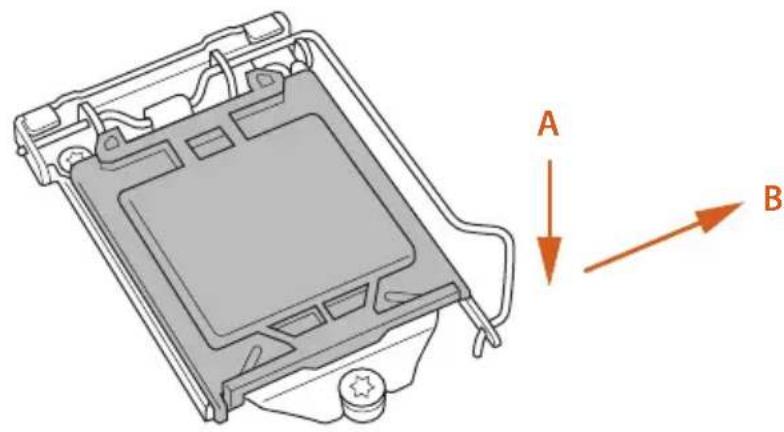
1
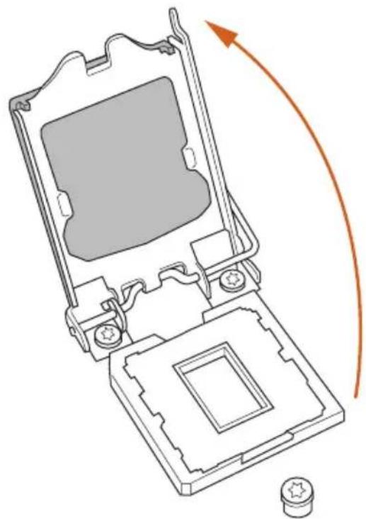
2
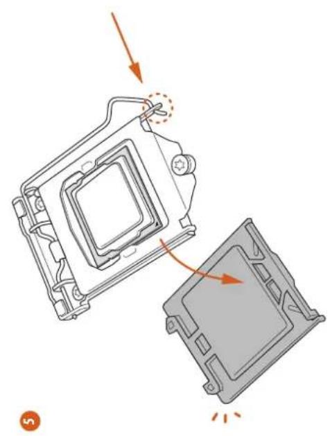

Please save and replace the cover if the processor is removed. The cover must be placed if you wish to return the motherboard for after service.
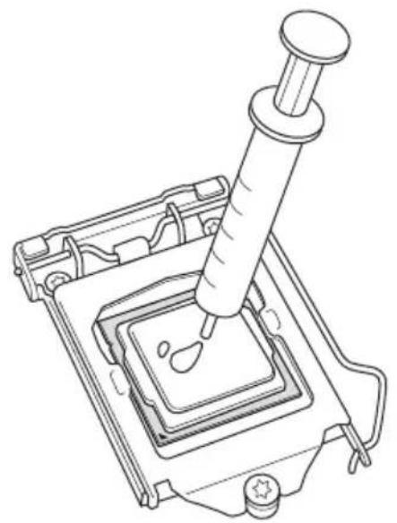
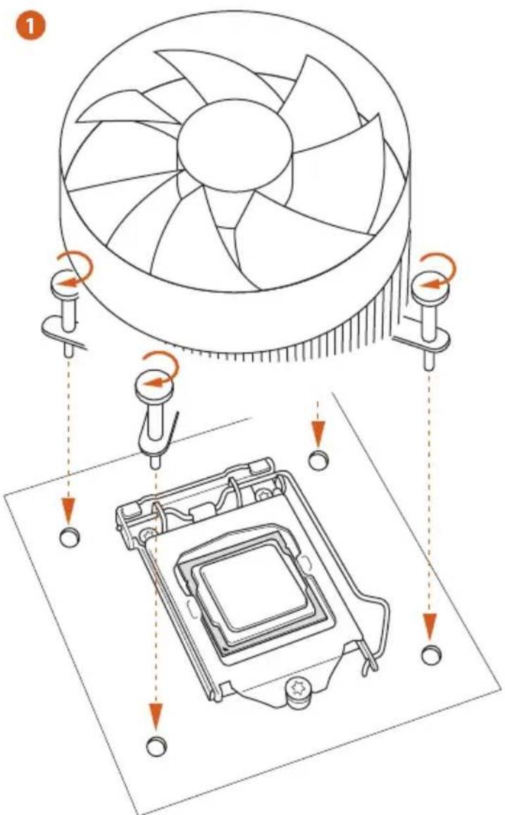
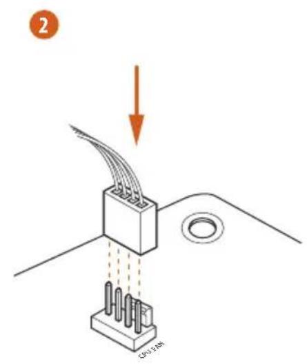
2.2 Installing the CPU Fan and Heatsink
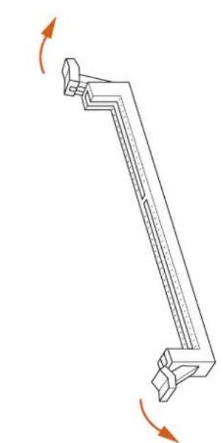
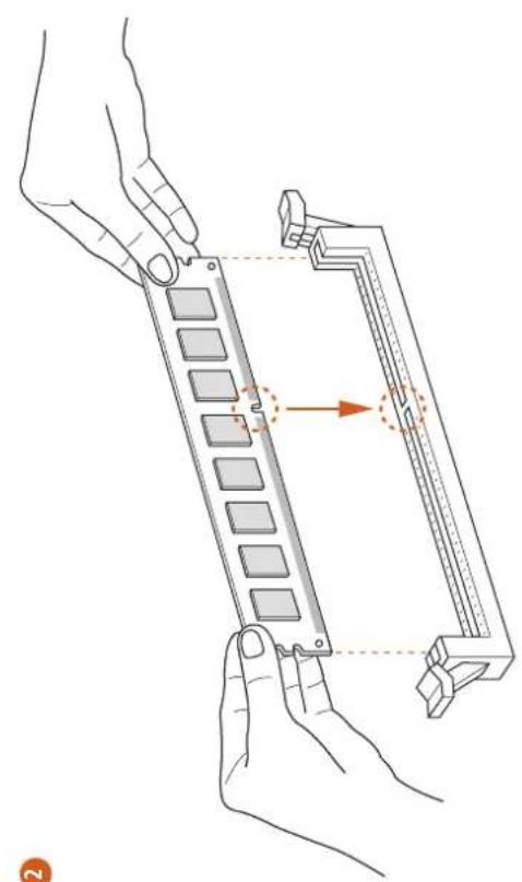
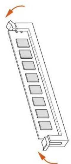
2.3 Installing Memory Modules (DIMM)
This motherboard provides four 240-pin DDR3 (Double Data Rate 3) DIMM slots, and supports Dual Channel Memory Technology.

- For dual channel configuration, you always need to install identical (the same brand, speed, size and chip-type) DDR3 DIMM pairs.
- It is unable to activate Dual Channel Memory Technology with only one or three memory module installed.
- It is not allowed to install a DDR or DDR2 memory module into a DDR3 slot; otherwise, this motherboard and DIMM may be damaged.
Dual Channel Memory Configuration
Priority DDR3_A1 DDR3_A2 DDR3_B1 DDR3_B2
1 Populated Populated
2 Populated Populated
3 Populated Populated Populated Populated

The DIMM only fits in one correct orientation. It will cause permanent damage to the motherboard and the DIMM if you force the DIMM into the slot at incorrect orientation.
English
2.4 Expansion Slots (PCI Express Slots)
There are 7 PCI Express slots on the motherboard.

Before installing an expansion card, please make sure that the power supply is switched off or the power cord is unplugged. Please read the documentation of the expansion card and make necessary hardware settings for the card before you start the installation.
PCIe slots:
PCIE1 (PCIe 2.0 x1 slots) is used for PCI Express x1 lane width cards.
PCIE2 (PCIe 3.0 x16 slot) is used for PCI Express x16 lane width graphics cards.
PCIE3 (PCIe 2.0 x1 slots) is used for PCI Express x1 lane width cards.
PCIE4 (PCIe 2.0 x1 slots) is used for PCI Express x1 lane width cards.
PCIE5 (PCIe 3.0 x16 slot) is used for PCI Express x8 lane width graphics cards.
PCIE6 (PCIe 2.0 x1 slots) is used for PCI Express x1 lane width cards.
PCIE7 (PCIe 3.0 x16 slot) is used for PCI Express x4 lane width graphics cards
PCIe Slot Configurations
PCIE2 PCIE5 PCIE7
Single Graphics Card x16 N/A N/A
Two Graphics Cards in
CrossFireX™ or SLI™ Mode
x8x8N / A
Three Graphics Cards in
3-Way CrossFireXTM Mode
x8 x4 x4

For a better thermal environment, please connect a chassis fan to the motherboard's chassis fan connector (CHA_FAN1, CHA_FAN2 or CHA_FAN3) when using multiple graphics cards.
2.5 Jumpers Setup
The illustration shows how jumpers are setup. When the jumper cap is placed on the pins, the jumper is "Short". If no jumper cap is placed on the pins, the jumper is "Open". The illustration shows a 3-pin jumper whose pin1 and pin2 are "Short" when a jumper cap is placed on these 2 pins.
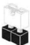
Short
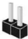
Open

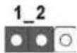
Clear CMOS Jumper (CLRCMOS1)
(see p.1, No. 19)
Clear CMOSDefault
CLRCMOS1 allows you to clear the data in CMOS. To clear and reset the system parameters to default setup, please turn off the computer and unplug the power cord from the power supply. After waiting for 15 seconds, use a jumper cap to short pin2 and pin3 on CLRCMOS1 for 5 seconds. However, please do not clear the CMOS right after you update the BIOS. If you need to clear the CMOS when you just finish updating the BIOS, you must boot up the system first, and then shut it down before you do the clear-CMOS action. Please be noted that the password, date, time, and user default profile will be cleared only if the CMOS battery is removed.
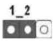
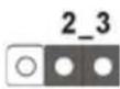
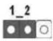
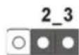
BIOS Selection Jumper
(BIOS_SEL1)
(see p.1, No. 17)
Default (Main BIOS)
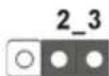
Backup BIOS
This motherboard has two BIOS onboard, a main BIOS (BIOS_A) and a backup BIOS (BIOS_B), which enhances protection for the safety and stability of your system. Normally, the system works on the main BIOS. However, if the main BIOS is corrupted or damaged, please use a jumper cap to short pin2 and pin3, then the backup BIOS will take over on the next system boot. After that, short pin1 and pin2 again, then use "Secure Backup UEFI" in BIOS setup utility to copy the BIOS file to the main BIOS to ensure normal system operation. For the sake of system safety, users cannot update the backup BIOS manually. Users may refer to the BIOS LED (BIOS_A_LED or BIOS_B_LED) to identify which BIOS is activated currently.
2.6 Onboard Headers and Connectors

Onboard headers and connectors are NOT jumpers. Do NOT place jumper caps over these headers and connectors. Placing jumper caps over the headers and connectors will cause permanent damage to the motherboard.
System Panel Header (9-pin PANEL1) (see p.1, No. 15)
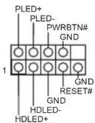
Connect the power switch, reset switch and system status indicator on the chassis to this header according to the pin assignments below. Note the positive and negative pins before connecting the cables.

PWRBTN (Power Switch):
Connect to the power switch on the chassis front panel. You may configure the way to turn off your system using the power switch.
RESET (Reset Switch):
Connect to the reset switch on the chassis front panel. Press the reset switch to restart the computer if the computer freezes and fails to perform a normal restart.
PLED (System Power LED):
Connect to the power status indicator on the chassis front panel. The LED is on when the system is operating. The LED keeps blinking when the system is in S1/S3 sleep state. The LED is off when the system is in S4 sleep state or powered off (S5).
HDLED (Hard Drive Activity LED):
Connect to the hard drive activity LED on the chassis front panel. The LED is on when the hard drive is reading or writing data.
The front panel design may differ by chassis. A front panel module mainly consists of power switch, reset switch, power LED, hard drive activity LED, speaker and etc. When connecting your chassis front panel module to this header, make sure the wire assignments and the pin assignments are matched correctly.
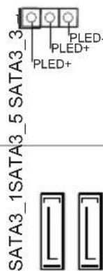
Power LED Header
(3-pin PLED1)
(see p.1, No. 14)
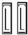
Serial ATA3 Connectors
(SATA3_0:
see p.1, No. 19)
(SATA3_1:
see p.1, No. 8)
(SATA3_2:
see p.1, No. 11)
(SATA3_3:
see p.1, No. 10)
(SATA3_4:
see p.1, No. 13)
(SATA3_5:
see p.1, No. 12)
aannnnnne aannnnnne
SATA3

Please connect the chassis power LED to this header to indicate the system's power status.
These six SATA3 connectors support SATA data cables for internal storage devices with up to 6.0 Gb/s data transfer rate.
USB 2.0 Headers
(9-pin USB4_5)
(see p.1, No. 20)
(9-pin USB6_7)
(see p.1, No. 21)
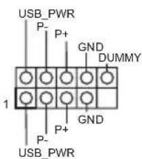
Besides four USB 2.0 ports on the I/O panel, there are two headers on this motherboard. Each USB 2.0 header can support two ports.
USB 3.0 Headers
(19-pin USB3_4_5)
(see p.1, No. 7)
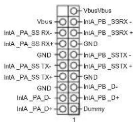
Besides four USB 3.0 ports on the I/O panel, there is one header on this motherboard. Each USB 3.0 header can support two ports.
Front Panel Audio Header (9-pin HD AUDIO01) (see p.1, No. 25)
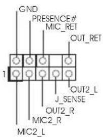
This header is for connecting audio devices to the front audio panel.

- High Definition Audio supports Jack Sensing, but the panel wire on the chassis must support HDA to function correctly. Please follow the instructions in our manual and chassis manual to install your system.
- If you use an AC'97 audio panel, please install it to the front panel audio header by the steps below:
A. Connect Mic_IN (MIC) to MIC2_L.
B. Connect Audio_R (RIN) to OUT2_R and Audio_L (LIN) to OUT2_L.
C. Connect Ground (GND) to Ground (GND).
D. MIC_RET and OUT_RET are for the HD audio panel only. You don't need to connect them for the AC'97 audio panel.
E. To activate the front mic, go to the "FrontMic" Tab in the Realtek Control panel and adjust "Recording Volume".
Chassis Speaker Header
(4-pin SPEAKER1)
(see p.1, No. 16)
DUMMY SPEAKER
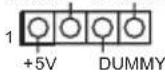
Please connect the chassis speaker to this header.
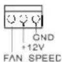
Chassis and Power Fan
Connectors
(4-pin CHA_FAN1)
(see p.1, No. 18)
Please connect fan cables to the fan connectors and match the black wire to the ground pin.
(3-pin CHA_FAN2)
(see p.1, No. 28)
(3-pin CHA_FAN3)
(see p.1, No. 27)
(3-pin PWR_FAN1)
(see p.1, No. 26)
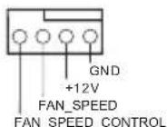
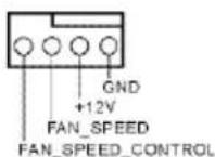
| CPU Fan Connectors
(4-pin CPU_FAN1)
(see p.1, No.3) | GND
112V
CPU_FAN_SPEED
FAN_SPEED_CONTROL | This motherboard pro-
vides a 4-Pin CPU fan
(Quiet Fan) connector.
If you plan to connect a
3-Pin CPU fan, please
connect it to Pin 1-3. |
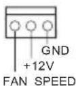
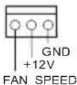
| (3-pin CPU_FAN2)
(see p.1, No.2) | GND
12V
CPU_FAN_speed | This motherboard pro-
vides a 24-pin ATX power
connector. To use a 20-pin
ATX power supply, please
plug it along Pin 1 and Pin
13. |
| ATX Power Connector
(24-pin ATXPWR1)
(see p.1, No.6) | 12
24
1
13 |
| ATX 12V Power
Connector
(8-pin ATX12V1)
(see p.1, No.1) | 8
5
4
1 | This motherboard pro-
vides an 8-pin ATX 12V
power connector. To use a
4-pin ATX power supply,
please plug it along Pin 1
and Pin 5. |
| SLI/XFIRE Power
Connector
(4-pin SLI/XFIRE_
PWR1)
(see p.1, No.22) | | Please connect this
connector with a hard
disk power connector
when two graphics cards
are installed on this
motherboard. |
| Infrared Module Header
(5-pin IR1)
(see p.1, No.23) | IRTX
+5VSB
DUMMY
1
GND
IRRX | This header supports an optional
wireless transmitting and
receiving infrared module. |
| Serial Port Header
(9-pin COM1)
(see p.1, No.24) | RRXD1
DDTR#1
DDS#1
CCTS#1
1
RRR#1
RRTS#1
TTXD1
DDCD#1 | This COM1 header
supports a serial port
module. |
1 Einleitung
Supporta DTS Connect
LAN
PCIE x1 LAN Gigabit 10/100/1000 Mb/s
Qualcomm Atheros Killer E2200 Serie
Supporta Wake-On-LAN
Supporta Energy Efficient Ethernet 802.3az
Supporta PXE
I/O pannello posteriore
- 1 x porta mouse/tastiera PS/2
- 1 x porta D-Sub
- 1xporta DVI-D
- 1 x porta HDMI-Out
- 1 x porta HDMI-In
- 1 x porta uscita SPDIF ottico
- 3 x porte USB 2.0
- 1 x porta mouse Fatality (USB 2.0)
4xporteUSB3.0
- 1 x porta LAN RJ-45 con LED (ACT/LINK LED e SPEED LED)
- Jack audio HD: altoparlante posteriore/centrale/basso/ ingresso linea/altoparlante anteriore/microfono
Archiviazione
- 6 x connettori SATA3 6,0 Gb/s, supporto RAID (RAID 0, RAID 1, RAID 5, RAID 10, technologia Intel Rapid Storage 12 e Tecnologia Intel Smart Response), NCQ, AHCI e "Hot Plug"
Connettore
Pa3bEmblIJIaBeHTnIaTOpOB Kopnyca N 6IOKaIITaHnI
(4-KoHTaKTHbI, CHA FAN1)
(CM. cTp. 1, N° 18)
IpeHa3HaueHb IJIa
IOKIOUeHN Ka6eIe
pa3bEMOB BeHTNIrTOPOB
IOKIOUeHN YepHO
IPOBOJa K 3a3EmJeHIO.
(3-KoHTaKTbI, CHA_FAN2)
(CM. ctp. 1, N° 28)
(3-KoHTaKTbH, CHA_FAN3)
(CM. cTp. 1, No 27)

(3-KOHTaKTbH, PWR FAN1)
(CM. cTp. 1, No 26)
PWRBTN (Güç Anahtar):
PLED (Sistem Güçü LED):
Clear CMOS 0 (CLRCMOS1)
(1.0019,19年国
Clear CMOS功能设置
864-bit/732-bit/764-bit
认证
If you need to contact ASRock or want to know more about ASRock, you're welcome to visit ASRock's website at http://www.asrock.com; or you may contact your dealer for further information. For technical questions, please submit a support request form at http://www.asrock.com/support/tsd.asp
ASRock Incorporation
2F., No.37, Sec. 2, Zhongyang S. Rd., Beitou District,
Taipei City 112, Taiwan (R.O.C.)
ASRock EUROPE B.V.
Bijsterhuizen 3151
6604 LV Wijchen
The Netherlands
Phone: +31-24-345-44-33
Fax: +31-24-345-44-38
ASRock America, Inc.
13848 Magnolia Ave, Chino, CA91710
U.S.A.
Phone: +1-909-590-8308
Fax: +1-909-590-1026

