
P202H Plus v2 - Router ZYXEL - Free user manual and instructions
Find the device manual for free P202H Plus v2 ZYXEL in PDF.
| Product Type | Router |
| Brand | ZyXEL |
| Model | P202H Plus v2 |
| Dimensions (L x W x H) | 220 x 150 x 40 mm |
| Weight | 0.3 kg |
| Power Supply | External power adapter 12 V DC, 1 A |
| Power Consumption | 12 W max |
| Key Features | NAT, firewall, VPN, routing, DHCP, QoS |
| Network Interfaces | 4 ports LAN 10/100 Mbps, 1 port WAN 10/100 Mbps |
| Supported Protocols | TCP/IP, UDP, ICMP, PPPoE, PPTP, L2TP |
| Simultaneous Users | Up to 30 |
| Security | SPI firewall, MAC filtering, access control |
| VPN | IPSec, PPTP, L2TP pass-through |
| Operating Temperature | 0°C to 40°C |
| Operating Humidity | 10% to 85% non-condensing |
| Care and Cleaning | Disconnect before cleaning, use a soft dry cloth |
| Spare Parts and Repairability | Spare parts not available to the public, contact after-sales service |
| Warranty | 2 years |
| General Information | Entry-level router for small businesses or homes |
Frequently Asked Questions - P202H Plus v2 ZYXEL
User questions about P202H Plus v2 ZYXEL
0 question about this device. Answer the ones you know or ask your own.
Ask a new question about this device
Download the instructions for your Router in PDF format for free! Find your manual P202H Plus v2 - ZYXEL and take your electronic device back in hand. On this page are published all the documents necessary for the use of your device. P202H Plus v2 by ZYXEL.
USER MANUAL P202H Plus v2 ZYXEL
-
What is ZyNOS? 6
-
How do I access the P-202H Plus v2 SMT menu? 6
-
What data compression protocol does the P-202H Plus v2 support? 6
-
What is the default console port baud rate? Moreover, how do I change it? 6
-
How do I upload the ZyNOS firmware code via console? 6
-
How do I upgrade/backup the ZyNOS firmware by using TFTP client program via LAN?......7
-
How do I upload ROMFILE via console port?......7
-
How do I backup/restore SMT configurations by using TFTP client program via LAN?......7
-
What should I do if I forget the system password? 8
-
What is SUA? When should I use SUA? 8
-
What is the difference between NAT and SUA?......8
-
How many network users can the SUA support?......9
-
How do I capture the PPP log in my P-202H Plus v2?......9
-
Why do we need the input filter in menu 3.1 and call filter in menu 11.1? 9
-
How can I protect against IP spoofing attacks? 9
-
What is DNS proxy?...... 10
-
What is a Nailed-up Connection and when do I need to use it?...... 11
-
What are Device filters and Protocol filters? 11
-
Why can't I configure device filters or protocol filters? 11
-
The P-202H Plus v2 supports to upload the firmware and configuration files using FTP, but how do I prevent the outside user from 'FTP' my P-202H Plus v2? 11
Product FAQ 12
-
How do I collect EPA trace? Moreover, how do I read it? 12
-
Can I prevent the dial-in user from occupying two channels?...... 12
-
How does 'Dial Prefix to Access Outside Line' in Menu 2 (European firmware) work?......12
-
What supplemental phone service does P-202H Plus v2 support..... 12
-
How do I do call waiting/call hold/call retrieve? 13
-
Why doesn't call waiting work as expected? 13
-
How do I do three way calling?...... 13
-
How do I remove a party from the three-way calling?...... 13
-
How do I do call transfer? 14
-
How do I blind call transfer? 14
-
What is call forwarding and how do I do it?...... 14
-
How do I suspend/resume a phone call (terminal portability)?...... 15
-
What is reminder ring? 15
-
Why doesn't my answering machine on POTS port stop recording? 15
-
What are CLIP and CLIR in Advanced Setup of Menu 2 (European firmware)?......15
- Does P-202H Plus v2 support MP callback to dial-in users? ..... 16
- Does ZyNOS support IRC, Real Player, CU-SeeMe and NetMeeting? 16
- What are the differences between P-202H, P-202H Plus and P-202H Plus v2? 16
Firewall FAQ....17 General....17 - What is a network firewall? 17
- What makes P-202H Plus v2 secure? 17
- What are the basic types of firewalls?...... 17
- What kind of firewall is the P-202H Plus v2? 18
- Why do you need a firewall when your router has packet filtering and NAT built-in? 18
- What is Denials of Service (DoS)attack?...... 18
- What is Ping of Death attack? 19
- What is Teardrop attack? 19
- What is SYN Flood attack? 19
- What is LAND attack? 19
11 What is Brute-force attack? 19 - What is IP Spoofing attack? 20
- What are the default ACL firewall rules in P-202H Plus v2?...... 20
- Why static/policy route be blocked by P-202H Plus v2? 20 Configuration 22
- How do I configure the firewall?...... 22
- How do I prevent others from configuring my firewall? 23
- Can I use a browser to configure my P-202H Plus v2? 23
- Why can't I configure my router using Telnet over WAN? 23
- Why can't I upload the firmware and configuration file using FTP over WAN? 23
- Why can't I configure my router using Telnet over LAN? 24
- Why can't I upload the firmware and configuration file using FTP over LAN? 24
Log and alert 24 - When does the P-202H Plus v2 generate the firewall log? 24
- What does the log show to us? 24
- How do I view the firewall log? 25
- When does the P-202H Plus v2 generate the firewall alert? 25
- What does the alert show to us? 25
- What is the difference between the log and alert? 26
IPSec Related FAQ 27
IPSec FAQ 27
VPN Overview 27 -
What is VPN? 27
-
Why do I need VPN? 27
-
What are most common VPN protocols?...... 28
-
What is PPTP? 28
-
What is L2TP? 28
-
What is IPSec? 28
-
What are the differences between 'Transport mode' and 'Tunnel mode? 28
-
What is SA? 29
-
What is IKE? 29
-
What is Pre-Shared Key? 29
-
What are the differences between IKE and manual key VPN?...... 29
-
How do I configure P-202H Plus v2 VPN? 30
-
How many VPN connections does P-202H Plus v2 support? ..... 30
-
What VPN protocols are supported by P-202H Plus v2 VPN? ...... 30
-
What types of encryption does P-202H Plus v2 VPN support? ..... 30
-
What types of authentication does P-202H Plus v2 VPN support? ... 30
-
I am planning my P-202H Plus v2-to-P-202H Plus v2 VPN configuration. What do I need to know? 30
-
Does P-202H Plus v2 support dynamic secure gateway IP?...... 31
-
What VPN gateway that has been tested with P-202H Plus v2 successfully? 31
-
What VPN software that has been tested with P-202H Plus v2 successfully? 32
-
Will ZyXEL support Secure Remote Management? 32
-
Does P-202H Plus v2 VPN support NetBIOS broadcast? 32
-
What are the difference between the 'My IP Address' and 'Secure Gateway IP Address' in Menu 27.1.1? 32
-
Is the host behind NAT allowed to use IPSec? 32
-
Why does VPN throughput decrease when staying in SMT menu 24.1? 33
-
How do I configure P-202H Plus v2 with NAT for internal servers? 33
SSH Sentinel FAQ 33
-
What is SSH Sentinel VPN client? 34
-
Why do I need to use Sentinel? 34
-
Does SSH Sentinel work with the PPP over Ethernet (PPPoE) protocol, which is used by the ADSL Network Adapter cards?...... 34
-
How to configure Pre-IPSec filter? 34
-
What is "Acquire virtual IP address" for? Should I check this box? 34
-
What is "Extended Authentication"? Should I check this box? ...... 34
-
Does Sentinel support IP range? 35
-
Does Sentinel support 2 VPN connections at the same time? ..... 35
-
What is this option, "Attach the selected values to proposal only" for? 35
-
How to initiate a VPN tunnel from Sentinel? 35
-
Can P-202H Plus v2 be the initiator of VPN tunnel to Sentinel? ..... 35
-
How can I verify if the VPN connection is up in Sentinel? 35
- I am using EnterNet 300, a PPPoE dial up software. Any concern? 35
Application Notes......35
General Application Notes 36
-
Internet Access ...... 36
-
SUA Applications....38
-
Dial-in User Setup....53
-
Filter 57
-
UNIX syslog Setup....88
7.ISDN Leased Line Setup 92
-
Supplemental Service 95
-
Using NetCAPI 98
-
Using RADIUS 103
-
Using CLID Callback.... 105
-
Using Multi-NAT.... 116
IPSec VPN 139
-
Using IPSec VPN.... 139
-
P-202H Plus v2 vs 3rd Party VPN Gateway 159
-
P-202H Plus v2 vs 3rd Party VPN Software 208
-
Configure NAT for Internal Servers 346
-
VPN Routing between Branch Offices 347
Support Tool 362
-
Using ZyXEL ISDN D Channel Analyzer, EPA 362
-
Using ZyXEL PPP Analyzer 366
-
LAN/WAN Packet Trace 370
-
Using TFTP to upload/download ZyNOS via LAN 381
-
Using FTP to Upload Firmware and Configuration Files 385
CI Command List.... 388
Troubleshooting 389
-
Internet Connection 389
-
Remote Node/Dial-in User Connection 394
-
IP Routing 401
-
Reset to default configuration file.... 404
Reference 406
1.ISDN Disconnection Cause....406
-
PPP Numbers......408
-
Port Numbers......421
-
Protocol Numbers 424
-
System Error Code 427
FAQ
ZyNOS FAQ
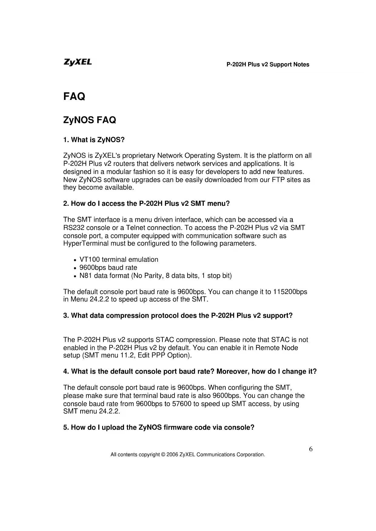
1. What is ZyNOS?
ZyNOS is ZyXEL's proprietary Network Operating System. It is the platform on all P-202H Plus v2 routers that delivers network services and applications. It is designed in a modular fashion so it is easy for developers to add new features. New ZyNOS software upgrades can be easily downloaded from our FTP sites as they become available.
2. How do I access the P-202H Plus v2 SMT menu?
The SMT interface is a menu driven interface, which can be accessed via a RS232 console or a Telnet connection. To access the P-202H Plus v2 via SMT console port, a computer equipped with communication software such as HyperTerminal must be configured to the following parameters.
• VT100 terminal emulation
• 9600bps baud rate
• N81 data format (No Parity, 8 data bits, 1 stop bit)
The default console port baud rate is 9600bps. You can change it to 115200bps in Menu 24.2.2 to speed up access of the SMT.
3. What data compression protocol does the P-202H Plus v2 support?
The P-202H Plus v2 supports STAC compression. Please note that STAC is not enabled in the P-202H Plus v2 by default. You can enable it in Remote Node setup (SMT menu 11.2, Edit PPP Option).
4. What is the default console port baud rate? Moreover, how do I change it?
The default console port baud rate is 9600bps. When configuring the SMT, please make sure that terminal baud rate is also 9600bps. You can change the console baud rate from 9600bps to 57600 to speed up SMT access, by using SMT menu 24.2.2.
5. How do I upload the ZyNOS firmware code via console?
The procedure for uploading via console is as follows.
a. Enter debug mode when powering on the P-202H Plus v2 using a terminal emulator
b. Enter 'ATUR' to start the uploading
c. Use X-modem protocol to transfer the ZyNOS code
d. Enter 'ATGO' to restart the P-202H Plus v2
6. How do I upgrade/backup the ZyNOS firmware by using TFTP client program via LAN?
The P-202H Plus v2 allows you to transfer the firmware from/to P-202H Plus v2 by using TFTP program via LAN. The procedure for uploading via TFTP is as follows.
a. Use the TELNET client program in your PC to login to your P-202H Plus v2, and use Menu 24.8 to enter CI command 'sys stdio 0' to disable console idle timeout.
b. To upgrade firmware, use TFTP client program to put firmware in file 'ras' in the P-202H Plus v2.
c. When the data transfer is finished, the P-202H Plus v2 will program the upgraded firmware into FLASH ROM and reboot itself.
d. To backup your firmware, use the TFTP client program to get file 'ras' from the P-202H Plus v2.
7. How do I upload ROMFILE via console port?
In some situations, such as losing the system password or the need of resetting SMT to factory default you may need to upload the ROMFILE.
The procedure for uploading via the console port is as follows.
a. Enter debug mode when powering on the P-202H Plus v2 using a terminal emulator
b. Enter 'ATUR3' to start the uploading
c. Use X-modem protocol to transfer ROMFILE
d. Enter 'ATGO' to restart the P-202H Plus v2
8. How do I backup/restore SMT configurations by using TFTP client program via LAN?
a. Use the TELNET client program in your PC to login to your P-202H Plus v2, and use Menu 24.8 to enter CI command 'sys stdio 0' to disable console idle timeout
b. To backup the SMT configurations, use TFTP client program to get file 'rom-0' from the P-202H Plus v2.
c. To restore the SMT configurations, use the TFTP client program to save your configuration in file 'rom-0' in the P-202H Plus v2.
9. What should I do if I forget the system password?
In case you forget the system password, you can upload ROMFILE to reset the SMT to factory default. After uploading ROMFILE, the default system password is '1234'.
10. What is SUA? When should I use SUA?
SUA (Single User Account) is a unique feature supported by P-202H Plus v2 router which allows multiple people to access Internet concurrently for the cost of a single user account.
When P-202H Plus v2 acting as SUA receives a packet from a local client destined for the outside Internet, it replaces the source address in the IP packet header with its own address and the source port in the TCP or UDP header with another value chosen out of a local pool. It then recomputes the appropriate header checksums and forwards the packet to the Internet as if it is originated from P-202H Plus v2 using the IP address assigned by ISP. When reply packets from the external Internet are received by P-202H Plus v2, the original IP source address and TCP/UDP source port numbers are written into the destination fields of the packet (since it is now moving in the opposite direction), the checksums are recomputed, and the packet is delivered to its true destination. This is because SUA keeps a table of the IP addresses and port numbers of the local systems currently using it.
11. What is the difference between NAT and SUA?
NAT is a generic name defined in RFC 1631 'The IP Network Address Translator (NAT)'.
SUA (Internet Single User Account) is ZyXEL's implementation and trade name for functioning PAT (Port Address Translation) which is a specific type of NAT. SUA( or PAT for NAT) translates address into port mapping.
The primary motivation for RFC 1631 is that there is not enough IP address to go around. In addition, great many corporations simply did not bother to obtain legal (globally unique) IP addresses for their networks and now finding themselves unable to connect to the Internet.
Basically, NAT is a process of translating one address to another. A NAT implementation can be as simple as substituting an IP address with another. This
allows a network to rectify the illegal address problem mentioned above without going through each and every host.
The aim of ZyXEL's SUA is to minimize the Internet access cost in a small office environment by using a single IP address to represent the multiple hosts inside. It does more than IP address translation, it also enables hosts on the LAN can access the Internet at the same time.
12. How many network users can the SUA support?
The fixed-size translation table limits the number of simultaneous. A reasonable number will be less than 20 users. Beyond that, the limited modem bandwidth would probably become the bottleneck and any increase in the translation table size will not help.
13. How do I capture the PPP log in my P-202H Plus v2?
The procedure to capture the PPP log in P-202H Plus v2 is as following.
To enable the capture of PPP log before a connection is established:
a. Enter SMT Menu 24.8, the CI command mode
b. Enter 'sys trcl cl' command
c. Enter 'sys trcl sw on' command
d. Enter 'sys trcp sw on' command
To display the PPP log after a connection is disconnected:
a. Enter 'sys trcl sw off' command
b. Enter 'sys trcp sw off' command
c. Enter 'sys trcl disp' command
14. Why do we need the input filter in menu 3.1 and call filter in menu 11.1?
Two factory default filter sets have been optimized for Internet connection. They are configured in menu 21 and applied to menu 3.1 and menu 11.5 to prevent NETBIOS triggering the call. You can remove it if you do not need it.
15. How can I protect against IP spoofing attacks?
The P-202H Plus v2's filter sets provide a means to protect against IP spoofing attacks. The basic scheme is as follows:
For the incoming data filter:
- Deny packets from the outside that claim to be from the inside
- Allow everything that is not spoofing us
Filter rule setup:
• Filter type = TCP/IP Filter Rule
- Active = Yes
- Source IP Addr =a.b.c.d
- Source IP Mask =w.x.y.z
• Action Matched = Drop
• Action Not Matched =Forward
Where a.b.c.d is an IP address on your local network and w.x.y.z is your netmask:
For the outgoing data filters:
- Deny bounceback packet
- Allow packets that originate from us
Filter rule setup:
• Filter Type = TCP/IP Filter Rule
- Active = Yes
- Destination IP Addr =a.b.c.d
- Destination IP Mask =w.x.y.z
• Action Matched = Drop
• Action No Matched =Forward
Where a.b.c.d is an IP address on your local network and w.x.y.z is your netmask.
16. What is DNS proxy?
If enabled, DNS Proxy allows the P-202H Plus v2 to act as the DNS server for the local network. The P-202H Plus v2 gets the IP address of the actual DNS server from the remote site via IPCP negotiation. Note this feature only works if the remote site supports RFC 1877.
How do I turn on DNS Proxy?
DNS Proxy is enabled only if the selection of the DHCP field under DHCP Setup in Menu 3.2 is Server and the Primary DNS Server is set to 0.0.0.0. (this is the factory default). If the DNS Proxy is enabled, the P-202H Plus v2 will assign its IP address as the Primary DNS in the responses to DHCP requests on the local network.
How do I set DNS other than P-202H Plus v2 IP address?
The P-202H Plus v2 assigns the values entered in Primary DNS server and Secondary DNS server fields in Menu 3.2 to the responses to the DHCP requests on the local network if the DHCP Server function is enabled.
- What is a Nailed-up Connection and when do I need to use it?
A Nailed-up Connection, when enabled, emulates a leased line connection even though the physical line is a dial-up connection. The P-202H Plus v2 dials and holds up a connection, without any traffic requesting it.
When you want the link to be always up, you need to use it.
- What are Device filters and Protocol filters?
In ZyNOS, the filters have been separated into two groups. One group is called 'device filter group', and the other is called 'protocol filter group'. Generic filters belong to the 'device filter group', TCP/IP and IPX filters belong to the 'protocol filter group'.
- Why can't I configure device filters or protocol filters?
In ZyNOS, you can not mix different filter groups in the same filter set.
- The P-202H Plus v2 supports to upload the firmware and configuration files using FTP, but how do I prevent the outside user from 'FTP' my P-202H Plus v2?
The P-202H Plus v2 supports to upload the firmware and configuration files using FTP connections via LAN and WAN. So, this becomes unsecure that anyone can make a FTP connection over the Internet to your P-202H Plus v2. To prevent from outside users connecting to your P-202H Plus v2 via FTP, you can configure a filter to block the FTP connection from WAN.
Product FAQ
- How do I collect EPA trace? Moreover, how do I read it?
- Enable the trace in Menu 24.8 by the following CI command:
isdn fw ana on
- Make a call to remote node or ISP by:
dev dial N (N is the remote node number)
- Drop the call by:
dev channel drop bri0|bri1 (bri0 for B1 channel, bri1 for B2 channel)
- Display the trace by:
isdn fw ana off isdn fw ana disp
- Can I prevent the dial-in user from occupying two channels?
Yes. You can use a CI command to prevent the dial-in user from occupying two channels.
Please enter to menu 24.8 and type the CI command:
ppp lcp mpin off (or on to allow two channels)
- How does 'Dial Prefix to Access Outside Line' in Menu 2 (European firmware) work?
This prefix will be placed in front of the outgoing call phone numbers when you make an outgoing call.
- What supplemental phone service does P-202H Plus v2 support
The P-202H Plus v2 supports the following supplementary phone features on both of its POTS ports.
- Call Waiting
-
Three Way Calling
-
Call Transfer
- Call Forwarding
- Reminder Ring
- Terminal Portability(Suspend/Resume)
Most supplementary services are not free, please check with your telephone company for the services they offer.
5. How do I do call waiting/call hold/call retrieve?
- Put your current call on hold and answer the incoming call - after hearing the call waiting tone, press and immediately release the Flash button on your telephone.
- Put your current call on hold and switch to another call - press and immediately release the Flash button on your telephone.
- Hang up your current call before answering the incoming call - hang up the phone and wait for answering the incoming call.
- Hang up the current active call and switch back to the other call - hang up and wait for the phone to ring. Then pick up the phone to return to the other call.
6. Why doesn't call waiting work as expected?
An incoming caller will receive a busy signal if:
- You have two calls active (one active and one on hold; or both active by using Three-Way Calling).
- You are dialing a number on the B channel the incoming caller is attempting to reach, but have not yet established a connection.
If no action is taken to answer the call (call waiting indicator tone is ignored), the call waiting tones will disappear after about 20 seconds.
7. How do I do three way calling?
- Press the Flash key to put the existing call on hold and receive a dial tone.
• Dial the third party's phone number. - When you are ready to conference the call together, press the Flash key again to establish a three way conference call.
8. How do I remove a party from the three-way calling?
Simply press the Flash key. The last call that was added to the conference is dropped.
If you hang up your telephone during a three-way call and the two other callers remain on the line, the ISDN network will do an implicit transfer to directly connect the two remaining callers together.
9. How do I do call transfer?
Call Transfer allows you to transfer an active call to a third party. This service must be subscribed from your telephone company.
Transferring an active call to a third party:
- Once you have an active call (Caller A), press Flash key to put Caller A on hold and receive a dial tone.
• Dial the third party's phone number (Caller B). - When you are ready to conference the two calls together, press Flash key to a Three-Way Conference call.
- Hang up the phone. The ISDN network does an implicit transfer to directly connect Caller A with Caller B.
10. How do I blind call transfer?
- Once you have an active call (Caller A), press Flash key to put the existing call on hold and receive a dial tone.
• Dial the third party's phone number (Caller B). - Before Caller B picks up the call, you can transfer the call by pressing the Flash key. The call is automatically transferred.
11. What is call forwarding and how do I do it?
The call forwarding means the switch will ring another number at a place where you will be when sometime dials your directory number. There are two methods to active call forwarding, either method should work fine and you can use whichever one you are most comfortable.
- The first is exactly the same as on an analog line, i.e., you pick up the handset and dial the access code assign by your telephone company and the number that you want the calls forwarded. Check with your telephone company for this access code.
- The second is with the 'phone flash' commands where you pick up the handset and press the flash key before dialing the following:
| Command Meaning | |
| *20*forward-number# Active CFB (Call Forwarding Busy) | |
| *21*forward-number# Active CFU (Call Forwarding | |
| Unconditional) | |
| *22*forward-number# Active CFNR (Call Forwarding No Reply | |
| #20# | Deactive |
| #21# | Deactive |
| #22# | Deactive |
CFB CFU CFNR
12. How do I suspend/resume a phone call (terminal portability)?
The Terminal Portability service allows you to suspend a phone call temporarily. You can then resume this call later, at another location if you so wish.
To suspend an active phone call:
- Press the flash key twice.
- Dial *3n*#, where n is any number from 1 to 9.
To resume your phone call:
- Reconnect at a (n) (ISDN) telephone that is linked to the same S/T interface (Network Terminator-1, NT1) where you suspended the call.
- Pick up the handset and press the Flash key
- Dial #3n#, where n is any number from 1 to 9, but should be identical to that used above.
13. What is reminder ring?
The P-202H Plus v2 sends a single short ring to your telephone every time a call has been forwarded(US switches only).
14. Why doesn't my answering machine on POTS port stop recording?
Most answering machines stop recording when a busy tone is detected. But some may not. Some answering machine only recognize that a calling party has hung up after a period of silence. In this case, if such an answering machine is attached to the POTS port of P-202H Plus v2 you need to configure the 'Hangup Silence Time(sec)' in SMT menu 2.1 to determine the silence time period. By doing so, once P-202H Plus v2 receives busy tones from the switch it sends the silence tone to the answering machine on POTS meanwhile.
15. What are CLIP and CLIR in Advanced Setup of Menu 2 (European firmware)?
CLIP or CLIR refers to CLID Presented or Restricted. The P-202H Plus v2 can set the CLIP/CLIR bit at SETUP message to request the Switch, to include the
calling party number or not when the switch sends the SETUP message to the called party. You need subscribe to it first (see supplemental services)
- Does P-202H Plus v2 support MP callback to dial-in users?
No, P-202H Plus v2 only supports single link PPP to dial-in users.
- Does ZyNOS support IRC, Real Player, CU-SeeMe and NetMeeting?
Yes. For the detail of the settings please refer to the Tested SUA Applications page.
- What are the differences between P-202H, P-202H Plus and P-202H Plus v2?
The differences between P-202H, P-202H Plus and P-202H Plus v2 are listed in the following table.
| Feature / Model | P-202H | P-202H Plus | P-202H Plus v2 |
| Ethernet Port 1 10/100M 4 10/100M 4 | 10/100M | ||
| a/b adapter 2 - - | |||
| Remote Access Server (Dial-in user support) | Y | Y | Y |
| RADIUS | Y | Y | Y |
| LAN-to-LAN Connection | Y | Y | Y |
| SNMP | Y(ZyNOS | 2.50) | Y |
| FTP firmware upload | Y(ZyNOS V2.41) Y Y | ||
| IP Policy Routing Y(ZyNOS 2.50) | Y Y | ||
| Mega Bundle | Y(ZyNOS 2.50) | Y Y | |
| IP Alias | Y(ZyNOS 2.50) | Y Y | |
| Firewall | - | Y | Y |
| VPN | - | Y | Y |
Firewall FAQ
General
1. What is a network firewall?
A firewall is a system or group of systems that enforces an access-control policy between two networks. It may also be defined as a mechanism used to protect a trusted network from an untrusted network. The firewall can be thought of two mechanisms. One to block the traffic, and the other to permit traffic.
2. What makes P-202H Plus v2 secure?
The P-202H Plus v2 is pre-configured to automatically detect and thwart Denial of Service (DoS) attacks such as Ping of Death, SYN Flood, LAND attack, IP Spoofing, etc. It also uses stateful packet inspection to determine if an inbound connection is allowed through the firewall to the private LAN. The P-202H Plus v2 supports Network Address Translation (NAT), which translates the private local addresses to one or multiple public addresses. This adds a level of security since the clients on the private LAN are invisible to the Internet.
3. What are the basic types of firewalls?
Conceptually, there are three types of firewalls:
- Packet Filtering Firewall
- Application-level Firewall
- Stateful Inspection Firewall
Packet Filtering Firewalls generally make their decisions based on the header information in individual packets. These header information include the source, destination addresses and ports of the packets.
Application-level Firewalls generally are hosts running proxy servers, which permit no traffic directly between networks, and which perform logging and auditing of traffic passing through them. A proxy server is an application gateway or circuit-level gateway that runs on top of general operating system such as UNIX or Windows NT. It hides valuable data by requiring users to communicate with secure systems by mean of a proxy. A key drawback of this device is performance.
Stateful Inspection Firewalls restrict access by screening data packets against defined access rules. They make access control decisions based on IP address and protocol. They also 'inspect' the session data to assure the integrity of the connection and to adapt to dynamic protocols. The flexible nature of Stateful
Inspection firewalls generally provides the best speed and transparency, however, they may lack the granular application level access control or caching that some proxies support.
4. What kind of firewall is the P-202H Plus v2?
- The P-202H Plus v2's firewall inspects packets contents and IP headers. It is applicable to all protocols, that understands data in the packet is intended for other layers, from network layer up to the application layer.
- The P-202H Plus v2's firewall performs stateful inspection. It takes into account the state of connections it handles so that, for example, a legitimate incoming packet can be matched with the outbound request for that packet and allowed in. Conversely, an incoming packet masquerading as a response to a nonexistent outbound request can be blocked.
- The P-202H Plus v2's firewall uses session filtering, i.e., smart rules, that enhance the filtering process and control the network session rather than control individual packets in a session.
- The P-202H Plus v2's firewall is fast. It uses a hashing function to search the matched session cache instead of going through every individual rule for a packet.
- The P-202H Plus v2's firewall provides email service to notify you for routine reports and when alerts occur.
5. Why do you need a firewall when your router has packet filtering and NAT built-in?
With the spectacular growth of the Internet and online access, companies that do business on the Internet face greater security threats. Although packet filter and NAT restrict access to particular computers and networks, however, for the other companies this security may be insufficient, because packets filters typically cannot maintain session state. Thus, for greater security, a firewall is considered.
6. What is Denials of Service (DoS)attack?
Denial of Service (DoS) attacks are aimed at devices and networks with a connection to the Internet. Their goal is not to steal information, but to disable a device or network so users no longer have access to network resources.
There are four types of DoS attacks:
- Those that exploits bugs in a TCP/IP implementation such as Ping of Death and Teardrop.
-
Those that exploits weaknesses in the TCP/IP specification such as SYN Flood and LAND Attacks.
-
Brute-force attacks that flood a network with useless data such as Smurf attack.
- IP Spoofing
7. What is Ping of Death attack?
Ping of Death uses a 'PING' utility to create an IP packet that exceeds the maximum 65535 bytes of data allowed by the IP specification. The oversize packet is then sent to an unsuspecting system. Systems may crash, hang, or reboot.
8. What is Teardrop attack?
Teardrop attack exploits weakness in the reassemble of the IP packet fragments. As data is transmitted through a network, IP packets are often broken up into smaller chunks. Each fragment looks like the original packet except that it contains an offset field. The Teardrop program creates a series of IP fragments with overlapping offset fields. When these fragments are reassembled at the destination, some systems will crash, hang, or reboot.
9. What is SYN Flood attack?
SYN attack floods a targeted system with a series of SYN packets. Each packet causes the targeted system to issue a SYN-ACK response, While the targeted system waits for the ACK that follows the SYN-ACK, it queues up all outstanding SYN-ACK responses on what is known as a backlog queue. SYN-ACKs are moved off the queue only when an ACK comes back or when an internal timer (which is set a relatively long intervals) terminates the TCP three-way handshake. Once the queue is full, the system will ignore all incoming SYN requests, making the system unavailable for legitimate users.
10. What is LAND attack?
In a LAN attack, hackers flood SYN packets to the network with a spoofed source IP address of the targeted system. This makes it appear as if the host computer sent the packets to itself, making the system unavailable while the target system tries to respond to itself.
11 What is Brute-force attack?
A Brute-force attack, such as 'Smurf' attack, targets a feature in the IP specification known as directed or subnet broadcasting, to quickly flood the target network with useless data. A Smurf hacker flood a destination IP address of each packet is the broadcast address of the network, the router will broadcast the ICMP echo request packet to all hosts on the network. If there are numerous
hosts, this will create a large amount of ICMP echo request packet, the resulting ICMP traffic will not only clog up the 'intermediary' network, but will also congest the network of the spoofed source IP address, known as the 'victim' network. This flood of broadcast traffic consumes all available bandwidth, making communications impossible.
12. What is IP Spoofing attack?
Many DoS attacks also use IP Spoofing as part of their attack. IP Spoofing may be used to break into systems, to hide the hacker's identity, or to magnify the effect of the DoS attack. IP Spoofing is a technique used to gain unauthorized access to computers by tricking a router or firewall into thinking that the communications are coming from within the trusted network. To engage in IP Spoofing, a hacker must modify the packet headers so that it appears that the packets originate from a trusted host and should be allowed through the router or firewall.
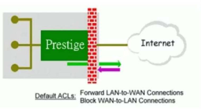
13. What are the default ACL firewall rules in P-202H Plus v2?
There are two default ACLs pre-configured in the P-202H Plus v2, one allows all connections from LAN to WAN and the other blocks all connections from WAN to LAN except of the DHCP packets.
flowchart
graph LR
    A["Default ACLs"] --> B["Prestige"]
    B --> C["Internet"]
    D["Forward LAN-to-WAN Connections"] --> E["Block WAN-to-LAN Connections"]
    E --> F["Internet"]
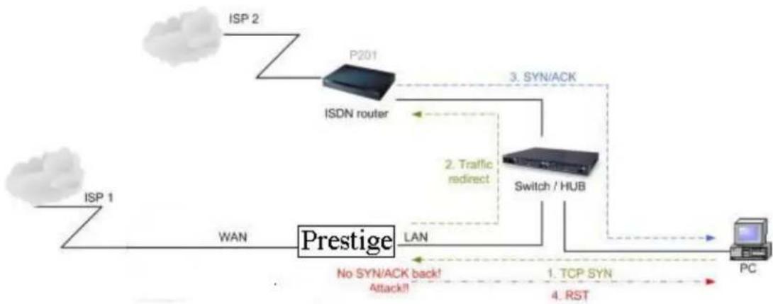
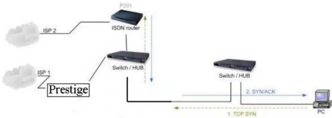
14. Why static/policy route be blocked by P-202H Plus v2?
P-202H Plus v2 is an ideal secure gateway for all data passing between the Internet and the LAN/DMZ. For some reasons (load balance or backup line), users may want traffic to be re-routed to another Internet access devices while still be protected by P-202H Plus v2. In such case, the network topology is the most important issue. Here is a common example that people mis-deploy the static route.
flowchart
graph TD
    ISP1["ISP 1"] -->|WAN| Prestige["Prestige"]
    Prestige -->|LAN| Switch/HUB["Switch / HUB"]
    Switch/HUB -->|3. SYN/ACK| P201["P201"]
    P201 -->|ISDN router| ISDN["ISDN router"]
    ISDN -->|2. Traffic redirect| Switch/HUB
    Switch/HUB -->|1. TCP SYN| PC["PC"]
    PC -->|4. RST| Switch/HUB
    style ISP1 fill:#f9f,stroke:#333
    style Prestige fill:#ccf,stroke:#333
    style Switch/HUB fill:#cfc,stroke:#333
    style PC fill:#fcc,stroke:#333
The above figure indicates the "triangle route" topology. It works fine if you turn off firewall function on P-202H Plus v2 box. However, if you turn on firewall, your connection will be blocked by firewall because of the following reason.
Step 1. Being the default gateway of PC, P-202H Plus v2 will receive all "outgoing" traffic from PC.
Step 2. And because of Static route/Policy Routing, P-202H Plus v2 forwards the traffic to another gateway (ISDN/Router) which is in the same segment as P-202H Plus v2's LAN.
Step 3. However the return traffic won't go back to P-202H Plus v2, in stead, the "another gateway (ISDN/Router)" will send back the traffic to PC directly. Because the gateway (say, P201) and the PC are in the same segment.
When firewall is turned on, P-202H Plus v2 will check the outgoing traffic by ACL and create dynamic sessions to allow return traffic to go back. To achieve Anti-DoS, P-202H Plus v2 will send RST packets to the PC and the peer since it never receives the TCP SYN/ACK packet. Thus the connection will always be reset by P-202H Plus v2.
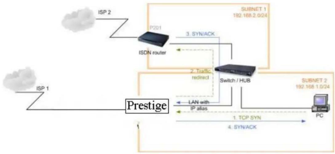
Solutions.
(A) Deploying your second gateway in IP alias segment is a better solution. In this way, your connection can be always under control of firewall. And thus there won't be Triangle Route problem.
flowchart
graph TD
    ISP1["ISP 1"] --> Prestige["Prestige"]
    Prestige -->|1. TCP SYN\n4. SYN/ACK| Switch/HUB["Switch / HUB"]
    Prestige -->|2. Traffic\nredirect| Switch/HUB
    Prestige -->|3. SYN/ACK| P201["ISDN router"]
    P201 -->|SUBNET 1\n192.168.2.0/24| Switch/HUB
    Switch/HUB -->|LAN with\nIP alias| Prestige
    Prestige --> PC["PC"]
(B) Deploying your second gateway on WAN side.
flowchart
graph TD
    A["IP 1"] --> B["Prestige"]
    C["ISP 2"] --> D["ISDN router"]
    E["ISP 1"] --> F["Switch / HUB"]
    G["P201"] --> D
    D --> H["Switch / HUB"]
    I["Switch / HUB"] --> J["PC"]
    K["1. TCP SYN"] --> L["2. SYN/ACK"]
    style A fill:#f9f,stroke:#333
    style C fill:#f9f,stroke:#333
    style E fill:#f9f,stroke:#333
    style G fill:#f9f,stroke:#333
    style I fill:#f9f,stroke:#333
    style K fill:#f9f,stroke:#333
    style B fill:#ccf,stroke:#333
    style D fill:#ccf,stroke:#333
    style F fill:#ccf,stroke:#333
    style H fill:#ccf,stroke:#333
    style J fill:#ccf,stroke:#333
    style L fill:#ccf,stroke:#333
(C) To resolve this conflict, we add an option for users to allow/disallow such Triangle Route topology in both CI command and Web configurator. You can issue this command, "sys firewall ignore triangle all on", to allow firewall bypass triangle route checking. In Web GUI, you can find this option in firewall setup page.
But we would like to notify that if you allow Triangle Route, any traffic will be easily injected into the protected network through the unprotected gateway. In fact, it's a security hole in protected your network.
Configuration
1. How do I configure the firewall?
P-202H Plus v2 supports a embedded web server so that you can use the web brower to configure it from any OS platform.
2. How do I prevent others from configuring my firewall?
There are several ways to protect others from touching the settings of your firewall.
- Change the default password since it is required when setting up the firewall using Telnet, Console or Web browser.
- Limit who can Telnet to your router. You can enter the IP address of the secured LAN host in SMT Menu 24.11 to allow Telnet to your P-202H Plus v2. The default value in this field is 0.0.0.0, which means you do not care which host is trying to Telnet your P-202H Plus v2.
3. Can I use a browser to configure my P-202H Plus v2?
Yes, you can use a web browser to configure the P-202H Plus v2.
4. Why can't I configure my router using Telnet over WAN?
There are three reasons that Telnet from WAN is blocked.
- When the firewall is turned on, all connections from WAN to LAN are blocked by the default ACL rule. To enable Telnet from WAN, you must turn the firewall off (Menu 21.2) or create a firewall rule to allow Telnet connection from WAN. The WAN-to-LAN ACL summary will look like as shown below.
Source IP= Telnet host Destination IP= router' WAN IP Service= TCP/23 Action=Forward
- You have disabled Telnet service in Menu 24.11.
- Telnet service is enabled but your host IP is not the secured host entered in Menu 24.11. In this case, the error message 'Client IP is not allowed!' is appeared on the Telnet screen.
- The default filter rule 3 (Telnet_FTP_WAN) is applied in the Input Protocol field in menu 11.5.
- The console port is in use.
5. Why can't I upload the firmware and configuration file using FTP over WAN?
- When the firewall is turned on, all connections from WAN to LAN are blocked by the default ACL rule. To enable FTP from WAN, you must turn the
firewall off (Menu 21.2) or create a firewall rule to allow FTP connection from WAN. The WAN-to-LAN ACL summary will look like as shown below.
Source IP= FTP host
Destination IP= P-202H Plus v2's WAN IP
Service= FTP TCP/21, TCP/20
Action=Forward
- You have disabled FTP service in Menu 24.11.
- The default filter rule 3 (Telnet_FTP_WAN) is applied in the Input Protocol field in menu 11.5.
6. Why can't I configure my router using Telnet over LAN?
- You have disabled Telnet service in Menu 24.11.
- Telnet service is enabled but your host IP is not the secured host entered in Menu 24.11. In this case, the error message 'Client IP is not allowed!' is appeared on the Telnet screen.
- The default filter rule 3 (Telnet_FTP_LAN) is applied in the Input Protocol field in menu 3.1.
- The console port is in use.
7. Why can't I upload the firmware and configuration file using FTP over LAN?
-
- You have disabled FTP service in Menu 24.11.
- The default filter rule 3 (Telnet_FTP_LAN) is applied in the Input Protocol field in menu 3.1.
Log and alert
1. When does the P-202H Plus v2 generate the firewall log?
The P-202H Plus v2 generates the log immediately when the packet match, doesn't match (or both) a firewall rule. The log for Default Permit (LAN to WAN, WAN to LAN) is generated automatically. To generate the log for custom rules, the Log option in Web Configurator must be set to Not Match, Match, or Both. The Reason column for the default permit shown in the log will be 'default permit, <1, 00> or <2, 00>'. Here <1, 00> means the LAN-to-WAN default ACL set, <2, 00> means the WAN-to-LAN default ACL set.
2. What does the log show to us?
The log supports up to 128 entries. There are 2 rows and 5 columns for each entry. Please see the example shown below.
| # Time | Packet Information | Reason | Action |
| 127 | |Mar 15 0 |From:192.168.1.34 To:202.132.155.93 |default permit |forward | 03:03:54|ICMP type:00008 code:00000 | |<1,00> | | |
Where
Y means the rule in the set. Because we can configure up to 10 rules in a set, so Y can be from 1 to 10. If the rule number shows 00, it means the Default Rule.
3. How do I view the firewall log?
The log keeps 128 entries, the new entries will overwrite the old entries when the log has over 128 entries.
There are three ways to view the firewall log:
- View the log from SMT Menu 21.3-View Firewall Log
- View the log using CI command-sys firewall display
- View the log from Web Configurator
4. When does the P-202H Plus v2 generate the firewall alert?
The P-202H Plus v2 generates the alert when an attack is detected by the firewall and sends it via Email. So, to send the alert you must configure the mail server and Email address using Web Configurator. You can also specify how frequently you want to receive the alert via Web Configurator.
5. What does the alert show to us?
The alert shown in the Email is actually the evens of the attack. So, the Reason column shows Attack and the attack type. Please see the example shown below.
| # Time | Packet Information | Reason | Action |
| 127 | Mar 15 0 | From:192.168.1.1 | To:192.168.1.1 |attack |block |
| | 03:04:54 | | ICMP | type:00008 | code:00000 |land | |
6. What is the difference between the log and alert?
A log entry is just added to the log inside the P-202H Plus v2 and e-mailed together with all other log entries at the scheduled time as configured. An alert is e-mailed immediately after an attacked is detected.
IPSec Related FAQ
IPSec FAQ
VPN Overview
1. What is VPN?
A VPN gives users a secure link to access corporate network over the Internet or other public or private networks without the expense of lease lines. A secure VPN is a combination of tunneling, encryption, authentication, access control and auditing technologies/services used to transport traffic over the Internet or any insecure network that uses the TCP/IP protocol suite for communication.
2. Why do I need VPN?
There are some reasons to use a VPN. The most common reasons are because of security and cost.
Security
1). Authentication
With authentication, VPN receiver can verify the source of packets and guarantee the data integrity.
2). Encryption
With encryption, VPN guarantees the confidentiality of the original user data.
Cost
1). Cut long distance phone charges
Because users typically dial the their local ISP for VPN, thus, long distance phone charge is reduced than making a long direct connection to the remote office.
2). Reducing number of access lines
Many companies pay monthly charges for two types access lines: (1) high-speed links for their Internet access and (2) frame relay, ISDN Primary Rate Interface or T1 lines to carry data. A VPN may allow a company to carry the data traffic over its Internet access lines, thus reducing the need for some installed lines.
3. What are most common VPN protocols?
There are currently three major tunneling protocols for VPNs. They are Point-to-Point Tunneling Protocol (PPTP), Layer 2 Tunneling Protocol (L2TP) and Internet Protocol Security (IPSec).
4. What is PPTP?
PPTP is a tunneling protocol defined by the PPTP forum that allows PPP packets to be encapsulated within Internet Protocol (IP) packets and forwarded over any IP network, including the Internet itself. The PPTP is supported in Windows NT and Windows 98 already. For Windows 95, it needs to be upgraded by the Dial-Up Networking 1.2 upgrade.
5. What is L2TP?
Layer Two Tunneling Protocol (L2TP) is an extension of the Point-to-Point Tunneling Protocol (PPTP) used by an Internet service provider (ISP) to enable the operation of a virtual private network (VPN) over the Internet.
6. What is IPSec?
IPSec is a set of IP extensions developed by IETF (Internet Engineering Task Force) to provide security services compatible with the existing IP standard (IPv.4) and also the upcoming one (IPv.6). In addition, IPSec can protect any protocol that runs on top of IP, for instance TCP, UDP, and ICMP. The IPSec provides cryptographic security services. These services allow for authentication, integrity, access control, and confidentiality. IPSec allows for the information exchanged between remote sites to be encrypted and verified. You can create encrypted tunnels (VPNs), or just do encryption between computers. Since you have so many options, IPSec is truly the most extensible and complete network security solution.
7. What secure protocols does IPSec support?
There are two protocols provided by IPSec, they are AH (Authentication Header, protocol number 51) and ESP (Encapsulated Security Payload, protocol number 50).
8. What are the differences between 'Transport mode' and 'Tunnel mode?
The IPSec protocols (AH and ESP) can be used to protect either an entire IP payload or only the upper-layer protocols of an IP payload. Transport mode is mainly for an IP host to protect the data generated locally, while tunnel mode is
for security gateway to provide IPSec service for other machines lacking of IPSec capability.
In this case, Transport mode only protects the upper-layer protocols of IP payload (user data). Tunneling mode protects the entire IP payload including user data.
There is no restriction that the IPSec hosts and the security gateway must be separate machines. Both IPSec protocols, AH and ESP, can operate in either transport mode and tunnel mode.
9. What is SA?
A Security Association (SA) is a contract between two parties indicating what security parameters, such as keys and algorithms they will use.
10. What is IKE?
IKE is short for Internet Key Exchange. Key Management allows you to determine whether to use IKE (ISAKMP) or manual key configuration to set up a VPN.
There are two phases in every IKE negotiation- phase 1 (Authentication) and phase 2 (Key Exchange). Phase 1 establishes an IKE SA and phase 2 uses that SA to negotiate SAs for IPSec.
11. What is Pre-Shared Key?
A pre-shared key identifies a communicating party during a phase 1 IKE negotiation. It is called 'Pre-shared' because you have to share it with another party before you can communicate with them over a secure connection.
12. What are the differences between IKE and manual key VPN?
The only difference between IKE and manual key is how the encryption keys and SPIs are determined.
- For IKE VPN, the key and SPIs are negotiated from one VPN gateway to the other. Afterward, two VPN gateways use this negotiated keys and SPIs to send packets between two networks.
- For manual key VPN, the encryption key, authentication key (if needed), and SPIs are predetermined by the administrator when configuring the security association.
IKE is more secure than manual key, because IKE negotiation can generate new keys and SPIs randomly for the VPN connection.
P-202H Plus v2 VPN
- How do I configure P-202H Plus v2 VPN?
You can configure P-202H Plus v2 for VPN using SMT or Web configurator. P-202H Plus v2 1 supports Web only.
- How many VPN connections does P-202H Plus v2 support?
One P-202H Plus v2 202H Plus supports 2 VPN connections.
- What VPN protocols are supported by P-202H Plus v2 VPN?
All P-202H Plus v2 series support ESP (protocol number 50) and AH (protocol number 51).
- What types of encryption does P-202H Plus v2 VPN support?
P-202H Plus v2 supports 56-bit DES and 168-bit 3DES.
- What types of authentication does P-202H Plus v2 VPN support?
VPN vendors support a number of different authentication methods. P-202H Plus v2 VPN supports both SHA1 and MD5.
AH provides authentication, integrity, and replay protection (but not confidentiality). Its main difference with ESP is that AH also secures parts of the IP header of the packet (like the source/destination addresses), but ESP does not.
ESP can provide authentication, integrity, replay protection, and confidentiality of the data (it secures everything in the packet that follows the header). Replay protection requires authentication and integrity (these two go always together). Confidentiality
(encryption) can be used with or without authentication/integrity. Similarly, one could use authentication/integrity with or without confidentiality.
- I am planning my P-202H Plus v2-to-P-202H Plus v2 VPN configuration. What do I need to know?
First of all, both P-202H Plus v2 must have VPN capabilities. Please check the firmware version, V3.50 or later has the VPN capability.
If your P-202H Plus v2 is capable of VPN, you can find the VPN options in Advanced>VPN tab.
For configuring a "box-to-box VPN", there are some tips:
- If there is a NAT router running in the front of P-202H Plus v2, please make sure the NAT router supports to pass through IPSec.
- In NAT case (either run on the frond end router, or in P-202H Plus v2 VPN box), only IPSec ESP tunneling mode is supported since NAT againsts AH mode.
- Source IP/Destination IP-- Please do not number the LANs (local and remote) using the same exact range of private IP addresses. This will make VPN destination addresses and the local LAN addresses are indistinguishable, and VPN will not work.
- Secure Gateway IP Address -- This must be a public, routable IP address, private IP is not allowed. That means it can not be in the 10.x.x.x subnet, the 192.168.x.x subnet, nor in the range 172.16.0.0 - 172.31.255.255 (these address ranges are reserved by internet standard for private LAN numberings behind NAT devices). It is usually a static IP so that we can pre-configure it in P-202H Plus v2 for making VPN connections. If it is a dynamic IP given by ISP, you still can configure this IP address after the remote P-202H Plus v2 is on-line and its WAN IP is available from ISP.
7. Does P-202H Plus v2 support dynamic secure gateway IP?
If the remote VPN gateways uses dynamic IP, we enter 0.0.0.0 as the Secure Gateway IP Address in P-202H Plus v2. In this case, the VPN connection can only be initiated from dynamic side to fixed side in order to update its dynamic IP to the fixed side. However, if both gateways use dynamic IP addresses, it is no way to establish VPN connection at all.
8. What VPN gateway that has been tested with P-202H Plus v2 successfully?
We have tested P-202H Plus v2 successfully with the following third party VPN gateways.
• Cisco 1720 Router, IOS 12.2(2)XH, IP/ADSL /FW/IDS PLUS IPSEC 3DES
• NetScreen 5, ScreenOS 2.6.0r6
- SonicWALL SOHO 2
- WatchGuard Firebox II
• ZyXEL P-202H Plus v2
- Avaya VPN
- Netopia VPN
- III VPN
9. What VPN software that has been tested with P-202H Plus v2 successfully?
We have tested P-202H Plus v2 successfully with the following third party VPN software.
• SafeNet Soft-PK, 3DES edition
- Checkpoint Software
- SSH Sentinel, 1.4
• SecGo IPSec for Windows
• F-Secure IPSec for Windows
• KAME IPSec for UNIX
• Nortel IPSec for UNIX
- Intel VPN, v. 6.90
- FreeS/WAN for Linux
- SSH Remote ISAKMP Testing Page, (http://isakmp-test.ssh.fi/cgi-bin/nph-isakmp-test)
- Windows 2000, IPSec
10. Will ZyXEL support Secure Remote Management?
Yes, we will support it and we are working on it currently.
11. Does P-202H Plus v2 VPN support NetBIOS broadcast?
The current 3.40 firmware release does not support it. But it is in our wish list.
12. What are the difference between the 'My IP Address' and 'Secure Gateway IP Address' in Menu 27.1.1?
'My IP Adderss' is the Internet IP address of the local P-202H Plus v2. The 'Secure Gateway IP Address' is the Internet IP address of the remote IPSec gateway.
13. Is the host behind NAT allowed to use IPSec?
| NAT Condition | Supported IPSec Protocol |
| VPN Gateway embedded NAT | AH tunnel mode, ESP tunnel mode |
| VPN client/gateway behind ESP tunnel mode | |
| NAT- | |
| NAT in Transport mode None | |
* The NAT router must support IPSec pass through. For example, for P-202H Plus v2 SUA/NAT routers, IPSec pass through is supported since ZyNOS 3.21. The default port and the client IP have to be specified in menu 15-SUA Server Setup.
14. Why does VPN throughput decrease when staying in SMT menu 24.1?
If P-202H Plus v2 stays in menu 24.1, 24.8 and 27.3 a certain of memory is allocated to generate the required statistics. So, we do not suggest to stay in menu 24.1, 27.3 and 24.8 when VPN is in use.
15. How do I configure P-202H Plus v2 with NAT for internal servers?
Generally, without IPSec, to configure an internal server for outside access, we need to configure the server private IP and its service port in SUA/NAT Server Table.
However, if both NAT and IPSec is enabled in P-202H Plus v2, the edit of the table is necessary only if the connection is a non-secure connections. For secure connections, none SUA server settings are required since private IP is reachable in the VPN case.
For example:
host----P-202H Plus v2(NAT)----Internet----Secure host \ Non-secure host
SSH Sentinel FAQ
1. What is SSH Sentinel VPN client?
Developed by SSH (http://www.ssh.com) Sentinel VPN client is a bundled software with P-202H Plus v2 VPN solution. It supports IPSec/VPN.
2. Why do I need to use Sentinel?
SSH Sentinel(TM) is an easy-to-use software for remote working based on the latest VPN technology. The software provides smooth integration with P-202H Plus v2 VPN which may be installed in HQ gateway.
3. Does SSH Sentinel work with the PPP over Ethernet (PPPoE) protocol, which is used by the ADSL Network Adapter cards?
Yes, the latest release SSH Sentinel 1.3, also supports PPPoE, but due to the wide range of PPPoE implementations and the fact, that we have a very limited access to PPPoE adapters in general, we are not able to fully test this functionality.
As a consequence, it is hard to say with exactly which PPPoE drivers SSH Sentinel 1.3 is fully compatible.
4. How to configure Pre-IPSec filter?
In pre-ipsec configuration, never, remove the pre-IPSec filter rule that bypasses IKE traffic. If you do, all your attempts to establish any IPSec connection are bound to fail, because the negotiations never take place. Only when you would like to have some TCP/UDP packets bypass IPSec, must you specify the traffic as bypass in pre-ipsec filter. Otherwise, just not setup any bypass/discard/reject on the traffic you would like to be protected by IPSec.
5. What is "Acquire virtual IP address" for? Should I check this box?
With this feature, Sentinel can obtain a virtual IP address assigned from VPN gateway. However, if connecting with P-202H Plus v2, please not check this box. P-202H Plus v2 doesn't support this feature in current firmware.
6. What is "Extended Authentication"? Should I check this box?
With this feature, VPN connection from Sentinel can be authenticated to authentication server, such as, RADIUS, TACAS, ...etc. behind remote VPN gateway. However, if connecting with P-202H Plus v2, please not check this box. P-202H Plus v2 doesn't support this feature in current firmware. It will support in the near future.
7. Does Sentinel support IP range?
No, only subnet/single is supported. So when connecting with P-202H Plus v2, please not use range as address type.
8. Does Sentinel support 2 VPN connections at the same time?
No, Sentinel doesn't support it. Only one VPN connection can be activated at the same time.
9. What is this option, "Attach the selected values to proposal only" for?
To increase compatibility, Sentinel sends many kinds of possible proposal for it's peer side, say P-202H Plus v2 to choose. If you uncheck this option, Sentinel will only send out the proposal you configured. To decrease negotiation time, you can uncheck this option, and verify phase1/phase2 parameters are consistent on both sides.
10. How to initiate a VPN tunnel from Sentinel?
Right click SSH icon in system tray, click the VPN connection you have setup in Select VPN. Packets triggering doesn't work in this case.
11. Can P-202H Plus v2 be the initiator of VPN tunnel to Sentinel?
No. Sentinel is supposed to be a VPN solution for remote access. Please always initiate your VPN tunnel from Sentinel but not from P-202H Plus v2.
12. How can I verify if the VPN connection is up in Sentinel?
You can check if your VPN connection is up by double clicking SSH icon in system tray. If the connection is up, you should see your VPN network in the popped out window.
13. I am using EnterNet 300, a PPPoE dial up software. Any concern?
If using EnterNet PPP over Ethernet client, the network access type must be set from the client's advanced connection settings to protocol driver. Open Enternet 300 Profiles window -> Connections -> Settings -> Advanced -> In Network Access section choose Protocol Driver.
Application Notes
General Application Notes
1. Internet Access
A typical Internet access application of the P-202H Plus v2 is shown below. For a small office, there are some components you need to check before accessing the Internet.
- Before you begin
The P-202H Plus v2 is shipped with the following factory default:
- IP address = 192.168.1.1, subnet mask = 255.255.255.0 (24 bits)
- DHCP server enabled with IP pool starting from 192.168.1.33
- Default SMT menu password = 1234
• Setting up the Win95/98 Workstation
1. Ethernet connection
All PCs must have an Ethernet adapter card installed.
- If you only have one PC, connect the PC's Ethernet adapter to the P-202H Plus v2's LAN port with a crossover (red one) Ethernet cable.
- If you have more than one PC, both the PC's Ethernet adapters and the P-202H Plus v2's LAN port must be connected to an external hub with straight Ethernet cable.
2. TCP/IP Installation
You must first install TCP/IP software on each PC before you can use it for Internet access. If you have already installed TCP/IP, go to the next section to configure it; otherwise, follow these steps to install:
• In the Control Panel/Network window, click Add button.
- In the Select Network Component Type windows, select Protocol and click Add.
- In the Select Network Protocol windows, select Microsoft from the manufacturers, then select TCP/IP from the Network Protocols and click OK.
3. TCP/IP Configuration
Follow these steps to configure Windows TCP/IP:
- In the Control Panel/Network window, click the TCP/IP entry to select it and click Properties button.
- In the TCP/IP Properties window, select Obtain an IP address automatically.
Note: Do not assign arbitrary IP address and subnet mask to your PCs, otherwise, you will not be able to access the Internet.
- Click the WINS configuration tab and select Disable WINS Resolution.
- Click the Gateway tab. Highlight any installed gateways and click the Remove button until there are none listed.
- Click the DNS Configuration tab and select Disable DNS.
- Click OK to save and close the TCP/IP properties window
- Click OK to close the Network window. You will be prompted to insert your Windows CD or disk. When the drivers are updated, you will be asked if you want to restart the PC. Make sure your P-202H Plus v2 is powered on before answering Yes to the prompt. Repeat the above steps for each Windows PC on your network.
- Setting up the P-202H Plus v2 router
The following procedure is for the most typical usage of the P-202H Plus v2 where you have a single-user account (SUA). The PNC (P-202H Plus v2 Network Commander) is a Windows-based tool that helps you to easily configure your P-202H Plus v2 for Internet access. It is included in the P-202H Plus v2 package. Please install the PNC first before configuring your P-202H Plus v2.
Example:
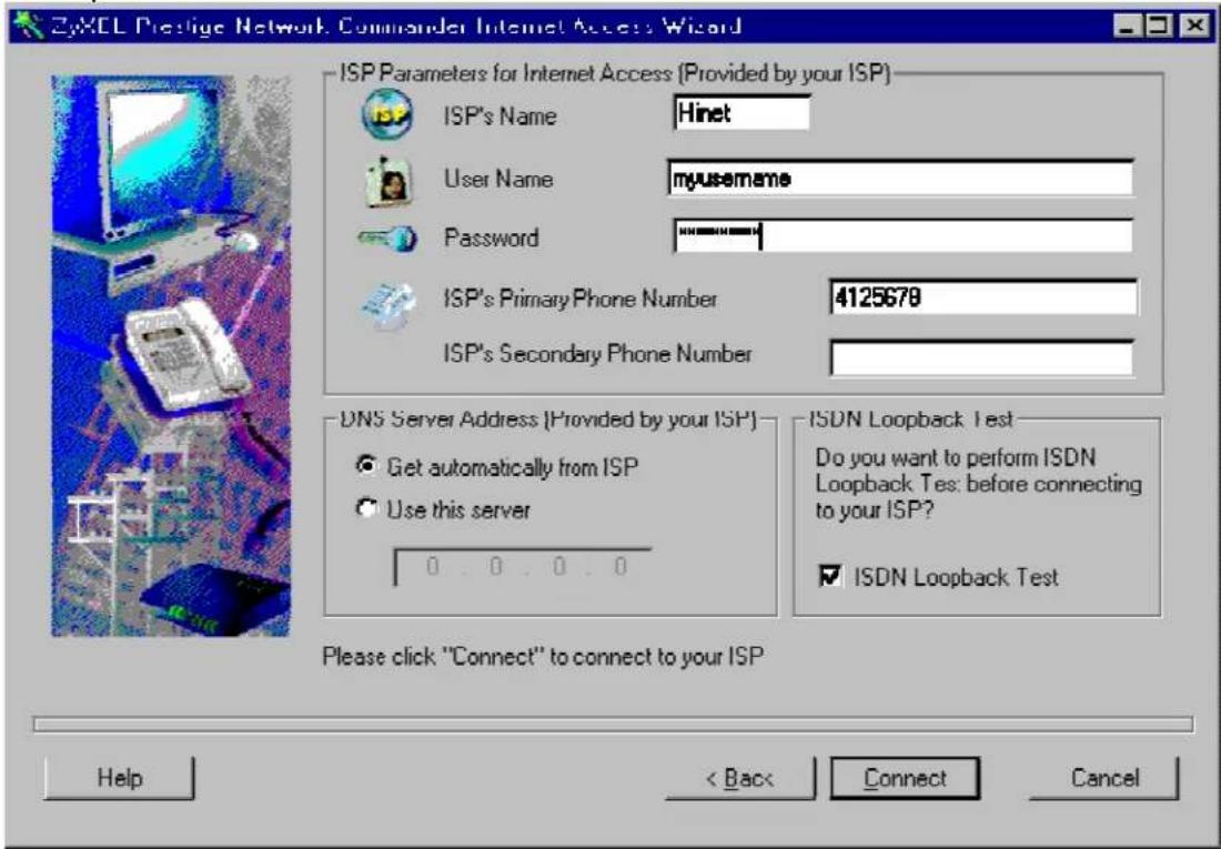
Key Settings:
- Pri Phone#= is the phone number your P-202H Plus v2 has to dial in order to access your ISP.
• My Login and My Password are the login information provided by ISP. - Since you have a single user Internet account, Single User Account should be set to 'Yes'.
- For the Local IP Address field, since the IP address will be dynamically assigned, you can either enter '0.0.0.0' or you can leave this field blank
After saving this menu, you will be asked if you want to perform an Internet connection test. Select 'Yes' to perform the test. If the test fails, please check again the above settings or refer to the User's Manual Troubleshooting section for correction action.
When you have configured and saved Menu 4, you should see that you have created a remote node in Menu 11. You can perform more advanced configuration options to this remote node in this menu.
2. SUA Applications
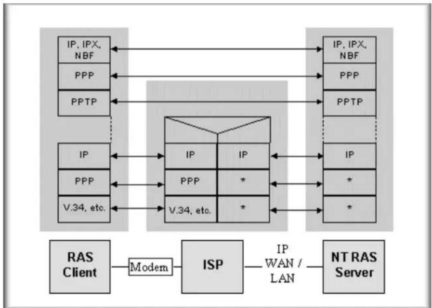
Configure a PPTP server behind SUA
- Introduction
PPTP is a tunneling protocol defined by the PPTP forum that allows PPP packets to be encapsulated within Internet Protocol (IP) packets and forwarded over any IP network, including the Internet itself.
In order to run the Windows9x PPTP client, you must be able to establish an IP connection with a tunnel server such as the Windows NT Server 4.0 Remote Access Server.
Windows Dial-Up Networking uses the Internet standard Point-to-Point (PPP) to provide a secure, optimized multiple-protocol network connection over dial-up telephone lines. All data sent over this connection can be encrypted and compressed, and multiple network level protocols (TCP/IP, NetBEUI and IPX) can be run correctly. Windows NT Domain Login level security is preserved even across the Internet.
flowchart
graph TD
    subgraph RAS Client
        A["IP, IPX, NBF"] <--> B["IP"]
        C["PPP"] <--> D["PPP"]
        E["PPTP"] <--> F["V.34, etc."]
    end

    subgraph ISP
        G["IP"] --> H["IP"]
        I["PPP"] --> J["*"]
        K["V.34, etc."] --> L["*"]
    end

    subgraph NT RAS Server
        M["IP, IPX, NBF"] <--> N["IP"]
        O["PPP"] <--> P["PPTP"]
        Q["IP"] <--> R["IP"]
        S["*"]
        T["*"]
    end

    A --> G
    C --> G
    E --> G
    F --> G
    H --> G
    J --> G
    L --> G
    N --> G
    O --> G
    P --> G
    R --> G
    S --> G
    T --> G
    U["Modem"] --> G
    V["WAN / LAN"] --> W["NTRAS Server"]
Window95 PPTP Client / Internet / NT RAS Server Protocol Stack
PPTP appears as new modem type (Virtual Private Networking Adapter) that can be selected when setting up a connection in the Dial-Up Networking folder. The VPN Adapter type does not appear elsewhere in the system. Since PPTP encapsulates its data stream in the PPP protocol, the VPN requires a second dial-up adapter. This second dial-up adapter for VPN is added during the installation phase of the Upgrade in addition to the first dial-up adapter that provides PPP support for the analog or ISDN modem.
The PPTP is supported in Windows NT and Windows 98 already. For Windows 95, it needs to be upgraded by the Dial-Up Networking 1.2 upgrade.
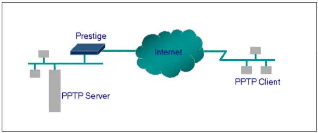
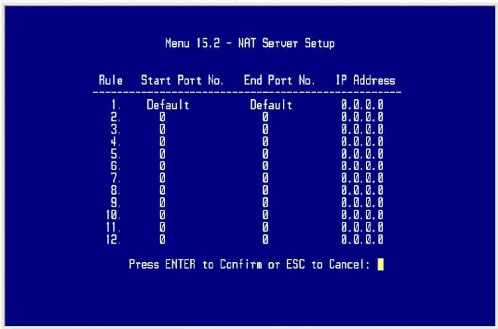
- Configuration
This application note explains how to establish a PPTP connection with a remote private network in the P-202H Plus v2 SUA case. In ZyNOS, all PPTP packets can be forwarded to the internal PPTP Server (WinNT server) behind SUA. The port number of the PPTP has to be entered in the SMT Menu 15 for P-202H Plus v2 to forward to the appropriate private IP address of Windows NT server.
flowchart
graph LR
    A["PPTP Server"] --> B["Prestige"]
    B --> C["Internet"]
    C --> D["PPTP Client"]
- Example
The following example shows how to dial to an ISP via the P-202H Plus v2 and then establish a tunnel to a private network. There will be three items that you need to set up for PPTP application, these are PPTP server (WinNT), PPTP client (Win9x) and the P-202H Plus v2.
o PPTP server setup (WinNT)
- Add the VPN service from Control Panel>Network
- Add an user account for PPTP logged on user
- Enable RAS port
- Select the network protocols from RAS such as IPX, TCP/IP NetBEUI
- Set the Internet gateway to P-202H Plus v2
o PPTP client setup (Win9x)
- Add one VPN connection from Dial-Up Networking by entering the correct username & password and the IP address of the P-202H Plus v2's Internet IP address for logging to NT RAS server.
- Set the Internet gateway to the router that is connecting to ISP
o P-202H Plus v2 router setup
- Before making a VPN connection from Win9x to WinNT server, you need to connect P-202H Plus v2 router to your ISP first.
- Enter the IP address of the PPTP server (WinNT server) and the port number for PPTP as shown below.
When you have finished the above settings, you can ping to the remote Win9x client from WinNT. This ping command is used to demonstrate that remote the Win9x can be reached across the Internet. If the Internet connection between two LANs is achieve, you can place a VPN call from the remote Win9x client.
For example:
C:\ping 203.66.113.2
When a dial-up connection to ISP is established, a default gateway is assigned to the router traffic through that connection. Therefore, the output below shows the default gateway of the Win95 client after the dial-up connection has been established.
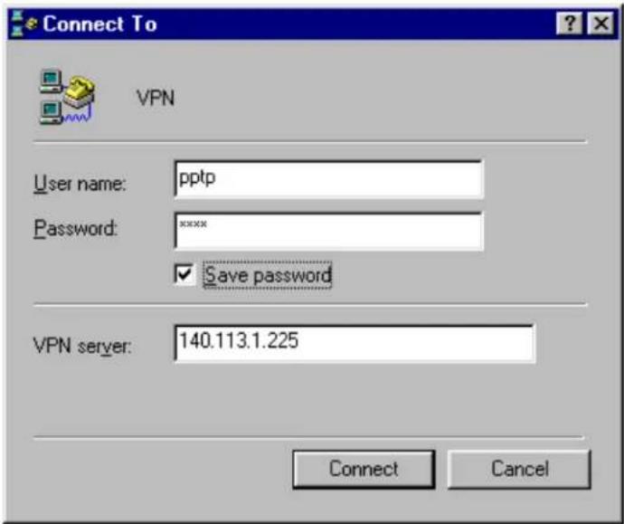
Before making a VPN connection from the Win9x client to the NT server, you need to know the exact Internet IP address that the ISP assigns to P-
202H Plus v2 router in SUA mode and enter this IP address in the VPN dial-up dialog box. You can check this Internet IP address from PNC Monitor or SMT Menu 24.1. If the Internet IP address is a fixed IP address provided by ISP in SUA mode, then you can always use this IP address for reaching the VPN server.
In the following example, the IP address '140.113.1.225' is dynamically assigned by ISP. You must enter this IP address in the 'VPN Server' dialog box for reaching the PPTP server. After the VPN link is established, you can start the network protocol application such as IP, IPX and NetBEUI.
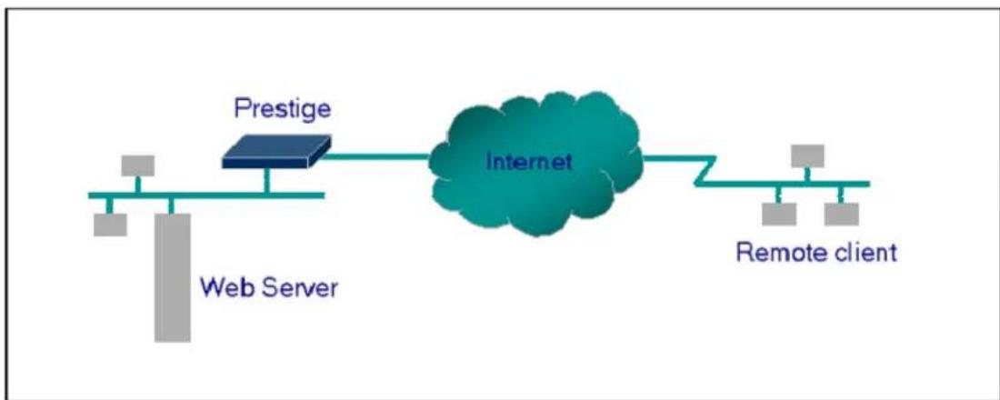
Configure an Internal Server Behind SUA
flowchart
graph LR
    A["Web Server"] --> B["Prestige"]
    B --> C["Internet"]
    C --> D["Remote client"]
- Introduction
If you wish, you can make internal servers (e.g., Web, ftp or mail server) accessible for outside users, even though SUA makes your LAN appear as a single machine to the outside world. A service is identified by the port number. Also, since you need to specify the IP address of a server in the P-202H Plus v2, a server must have a fixed IP address and not be a DHCP client whose IP address potentially changes each time it is powered on.
In addition to the servers for specific services, SUA supports a default server. A service request that does not have a server explicitly designated for it is forwarded to the default server. If the default server is not defined, the service request is simply discarded.
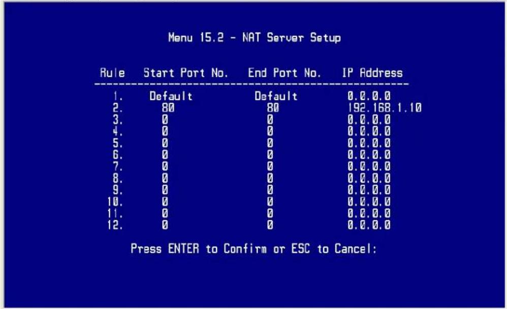
- Configuration
To make a server visible to the outside world, specify the port number of the service and the inside address of the server in 'Menu 15', Multiple Server Configuration. The outside users can access the local server using the P-202H Plus v2's WAN IP address which can be obtained from menu 24.1.
- For example (Configuring an internal Web server for outside access):
• Port numbers for some services
| Service Port Number | |
| FTP | 21 |
| Telnet | 23 |
| SMTP | 25 |
| DNS (Domain Name Server) 53 | |
| www-http (Web) 80 |
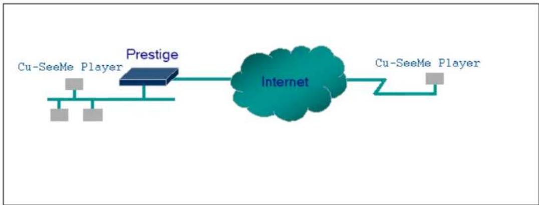
Tested SUA Applications (e.g., Cu-SeeMe, ICQ, NetMeeting)
flowchart
graph LR
    A["Cu-SeeMe Player"] --> B["Prestige"]
    B --> C["Internet"]
    C --> D["Cu-SeeMe Player"]
- Introduction
Generally, SUA makes your LAN appear as a single machine to the outside world. LAN users are invisible to outside users. However, some applications such as Cu-SeeMe, and ICQ will need to connect to the local user behind the P-202H Plus v2. In such case, a SUA server must be entered in menu 15 to forward the incoming packets to the true destination behind SUA. Generally, we do not need extra settings of menu 15 for an outgoing connection. But for some applications we need to configure the menu 15 to make the outgoing connection work. After the required menu 15 settings are completed the internal server or client applications can be accessed by using the P-202H Plus v2's WAN IP address.
• SUA Supporting Table
The following are the required menu 15 settings for the various applications running SUA mode.
ZyXEL SUA Supporting Table ^1
| Application | Required Settings in Menu 15 Port/IP | |
| Outgoing Connection | Incoming Connection | |
| HTTP | None | 80/client |
| FTP | None | 21/client |
| TELNET None 23/client IP | (and remove Telnet filter in WAN port) | |
| POP3 | None | 110/clinet |
| SMTP | None | 25/client |
| mIRC | None for Chat.For DCC, please setDefault/Client IP | . |
| Windows PPTP None 1723/client IP | ||
| ICQ 99a None for Chat. | For DCC, please set:ICQ -> preference ->connections -> firewall andset the firewall time out to80 seconds in firewallsetting. | Default/client IP |
| Cornell 1.1 Cu-SeeMe None 7648/client IP | ||
| White Pine 3.1.2 Cu-SeeMe 7648/client IP &24032/client IP | Default/client IP | |
| White Pine 4.0 Cu-SeeMe 7648/client IP &24032/client IP | Default/client IP | |
| Microsoft NetMeeting 2.1 &2.11 | None 1720/client IP | 1503/client IP |
| Cisco IP/TV 2.0.0 None . | ||
| RealPlayer G2 | None . | |
| VDOLive | None | . |
| Quake1.06^4 | None | Default/client IP |
| QuakeII2.30^5 | None | Default/client IP |
| QuakelIII1.05 beta | None . | |
| StartCraft. | 6112/client IP | . |
| Quick Time 4.0 | None | . |
| pcAnywhere 8.0 None | 5631/client IP5632/client IP22/client IP | |
^1 Since SUA enables your LAN to appear as a single computer to the Internet, it is not possible to configure similar servers on the same LAN behind SUA.
^2 Because White Pine Cu-SeeMe uses dedicate ports (port 7648 & port 24032) to transmit and receive data, therefore only one local Cu-SeeMe is allowed within the same LAN.
^3 With SUA enabled, NetMeeting users within the same LAN will not be able to connect to the remote NetMeeting user, and as remote users are not able to distinguish between local users with the same internet IP and SUA allows one local NetMeeting user to connect to multiple Internet users at the same time.
^4 Certain Quake servers do not allow multiple users to login using the same unique IP, so only one Quake user will be allowed in this case. Moreover, when a Quake server is configured behind SUA, P-202H Plus v2 will not be able to provide information of that server on the internet.
^5 Quake II has the same limitations as that of Quake I.
Notes
-
If a SMTP (port 25) server is configured in menu 15 the POP3 (port 110) packets will also be forwarded to the same SMTP server by the P-202H Plus v2 automatically. There is no need to configure additional POP3 server in menu 15. Two ports (25 & 110) must be configured in menu 15 to support both SMTP and POP3 services.
-
NetMeeting, RealPlayer, IP/TV and Quick Time are supported.
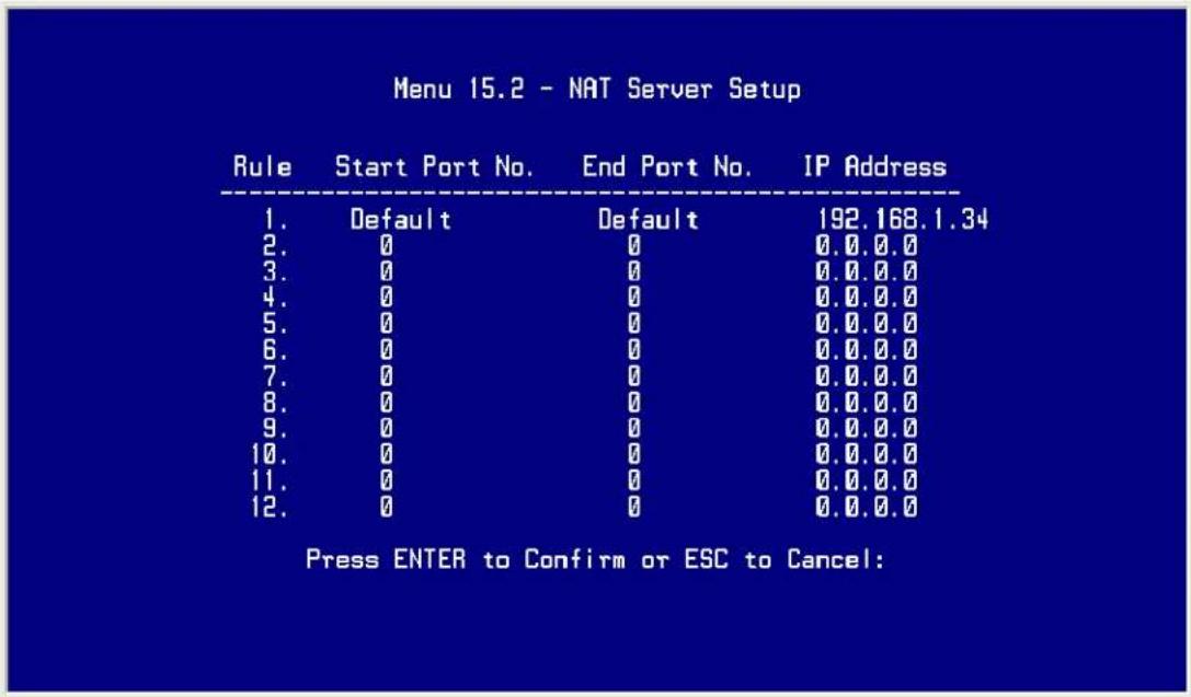
- Configurations
For example, if the workstation operating Cu-SeeMe has an IP of 192.168.1.34, then the default SUA server must be set to 192.168.1.34. The peer Cu-SeeMe user can reach this workstation by using P-202H Plus v2's WAN IP address which can be obtained from menu 24.1.
3. LAN to LAN
IP Connection
- Introduction
This configuration note explains how to set up two P-202H Plus v2 routers for a LAN-to-LAN connection. Once the connection is established, the workstations on both LANs will be able to perform any TCP/IP applications (e.g., FTP, Telnet, etc.). There will be three items that you need to set up. These are workstation and the two P-202H Plus v2 routers.
- Configuration

flowchart
graph LR
    A["Terminal"] --> B["Prestige 1"]
    B --> C["Prestige 2"]
    C --> D["Terminal"]
- Setting up the workstation on both LANs
To set up the workstations, you will need to set the following parameters:
- IP Address-the IP address assigned to the workstation itself
- Subnet Mask-the subnet mask used for your network. Class C networks generally use a 24-bit netmask DNS (Domain Name Server) Address-enter the IP address of the DNS server
Default Gateway-the IP address of the P-202H Plus v2, the default gateway for LAN1 is P-202H Plus v2 1 and for LAN2 is P-202H Plus v2 2.
The procedure for configuring these parameters for the workstations may differ depending on the type of TCP/IP networking software you are using on your workstations. If you are unfamiliar with how to set these parameters, you can refer to the technical notes corresponding to your software.
For Windows 9x, please go to 'Win9x>Control Panel>Network>TCP/IP-Network Adapter' for finishing the above settings.
- Setting up the P-202H Plus v2 1 & P-202H Plus v2 2
Before configuring the two remote nodes for this application, you need to complete the following settings first in each P-202H Plus v2.
- General Setup in SMT Menu 1-enter the system information.
- ISDN Setup in SMT Menu 2- configure the ISDN parameters.
- Ethernet Setup in SMT Menu 3-enter the IP address of the P-202H Plus v2 and enable the DHCP server if it is required.
o Remote Node Setup in SMT Menu 11
• P-202H Plus v2 1 Setup
1. Ethernet Setup in SMT Menu 3
Menu 3.2 - TCP/IP and DHCP Ethernet Setup
DHCP Setup:
DHCP= None
Client IP Pool Starting Address= N/A
Size of Client IP Pool= N/A
Primary DNS Server= N/A
Secondary DNS Server= N/A
TCP/IP Setup:
IP Address= 202.113.5.1
IP Subnet Mask= 255.255.255.0
RIP Direction= Both
Version= RIP-2B
Edit IP Alias= No
2. Remote Node Setup in SMT Menu 11
Menu 11.1 - Remote Node Profile
Rem Node Name= LAN2
Edit PPP Options= No
Active= Yes
Rem IP Addr= 203.66.113.1
Call Direction=Outgoing
Edit IP= No
Incoming:
Telco Option:
Rem Login=
Transfer Type= 64K
Rem Password=
Allocated Budget(min)=
Rem CLID= N/A
Period(hr)=
Call Back= N/A
Schedules=
Outgoing:
Carrier Access Code=
My Login= test
Nailed-Up Connection= No
My Password= *****
Toll Period(sec)= 0
Authen= CHAP/PAP
Session Options:
Pri Phone #= 5007025
Edit Filter Sets= No
Sec Phone #=
Idle Timeout(sec)= 100
Press ENTER to Confirm or ESC to Cancel:
Key Settings:
- Select the 'Active' field to 'Yes'
- Select the 'Call Direction' to 'Outgoing'
- Enter the correct node account in 'My Login' and 'My Password' fields
- Enter the phone number of the remote router in the 'Pri Phone #' field
- Enter the IP address of the remote router in 'Rem IP Addr' field
- Enter the idle timer in the 'Idle Timeout' field for dropping the call if there is no data traffic between the two remote nodes
• P-202H Plus v2 2 Setup
1. Ethernet Setup in SMT Menu 3
Menu 3.2 - TCP/IP and DHCP Ethernet Setup
DHCP Setup:
DHCP= None
Client IP Pool Starting Address= N/A
Size of Client IP Pool= N/A
Primary DNS Server= N/A
Secondary DNS Server= N/A
TCP/IP Setup:
IP Address= 203.66.113.1
IP Subnet Mask= 255.255.255.0
RIP Direction= Both
Version= RIP-2B
Edit IP Alias= No
- Remote Node Setup in SMT Menu 11
Menu 11.1 - Remote Node Profile
Rem Node Name= LAN2
Active= Yes
Call Direction= Outgoing
Edit PPP Options= No
Rem IP Addr=202.113.5.1
Edit IP= No
Incoming:
Rem Login=
Rem Password=
Rem CLID= N/A
Call Back= N/A
Outgoing:
My Login= test
My Password= *****
Authen= CHAP/PAP
Pri Phone #= 5007025
Sec Phone #=
Telco Option:
Transfer Type= 64K
Allocated Budget(min)=
Period(hr)=
Schedules=
Carrier Access Code=
Nailed-Up Connection= No
Toll Period(sec)= 0
Session Options:
Edit Filter Sets= No
Idle Timeout(sec)= 100
Press ENTER to Confirm or ESC to Cancel:
Key Settings:
- Select the 'Active' field to 'Yes'
- Select the 'Call Direction' to 'Incoming'
- Enter the correct node account for the dial-in router in 'Rem Login' and 'Rem Password' fields
- Enter the IP address of the remote router in 'Rem IP Addr' field.
After you have finished the above settings, you are ready to make a test for this connection from Menu 24.4.5- 'Manual Call' by entering the node number.
Menu 24.4 - System Maintenance - Diagnostic
ISDN
System
- Hang Up B1 Call
- Reboot System
- Hang Up B2 Call
- Command Mode
- Reset ISDN
- ISDN Connection Test
- Manual Call
TCP/IP
- Internet Setup Test
- Ping Host
Enter Menu Selection Number:
Manual Call Remote Node= N/A
Host IP Address= N/A
Configuring for Cisco Mutual Authentication
- Introduction
This configuration note explains what other settings you need to pay attention to when configuring the P-202H Plus v2 talk to a Cisco router. Due to Cisco's authentication scheme, you need to configure some additional fields in P-202H Plus v2 when talking to a Cisco device. There are two things you must pay attention to. The first is Cisco's mutual authentication scheme, and the second is their interpretation of CHAP.
- Configuration
- If the Cisco router requests PAP, you have to configure more settings in Menu 13 as follows.
Menu 13 - Default Dial-in Setup
Telco Options: IP Address Supplied By:
CLID Authen= None Dial-in User= Yes
IP Pool= No
PPP Options: IP Start Addr= N/A
Recv Authen= CHAP/PAP IP Count(1,4)= N/A
Compression= Yes
Mutual Authen= Yes Session Options:
O/G Username= test Edit Filter Sets= No
O/G Password= *
Multiple Link Options:
Max Trans Rate(Kbps)= 128
Callback Budget Management:
Allocated Budget(min)= 0
Period(hr)= 0
Press ENTER to Confirm or ESC to Cancel:
Key Settings:
- Set 'Mutual Authen' to 'Yes'
- Set 'PAP Login' to the appropriate login name
- Set 'PAP Password' to the appropriate login password
- If the Cisco route requests CHAP, you have to configure more settings in Menu 11 as follows.
Menu 11.1 - Remote Node Profile
Rem Node Name= LAN2 Edit PPP Options= No
Active= Yes Rem IP Addr=140.113.1.1
Call Direction= Both Edit IP= No
Incoming: Telco Option:
Rem Login= [cisco_hostname] Transfer Type= 64K
Rem Password= **** Allocated Budget(min)=
Rem CLID= N/A Period(hr)=
Call Back= N/A Schedules=
Outgoing: Carrier Access Code=
My Login= [P-202H Plus v2_systemname] Nailed-Up Connection= No
My Password= ***** Toll Period(sec)= 0
Authen= CHAP/PAP Session Options:
Pri Phone #= 10000 Edit Filter Sets= No
Sec Phone #= Idle Timeout(sec)= 100
Press ENTER to Confirm or ESC to Cancel:
Key Settings:
- Set 'Incoming: Rem Login' to the 'Cisco device hostname'
- Set 'Incmoing: Rem Password' to be the same as 'Outgoing: My Password'
Set 'Outgoing: My Login' to the 'System Name' value in SMT Menu 1
[Note]! The Cisco device must be configured as a remote node but NOT as a remote user in this case
4. Dial-in User Setup
Using an ISDN TA and Win9x Dial-Up Networking you can dial into P-202H Plus v2 router with callback and without callback
- Introduction
This configuration note explains how to set up a workstation using an ISDN TA to connect to the P-202H Plus v2 router. In this configuration, the workstation must have TCP/IP dial-up program installed such as Windows Dial-up Networking to make the call. Once the connection is established, the workstation will be able to
perform any TCP/IP applications (e.g., FTP, Telnet, etc.). There will be two items that you need to set up for this connection. They are the workstation and the P-202H Plus v2 router.
- Configuration
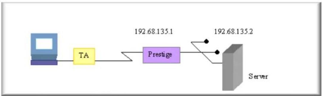
flowchart
graph LR
    A["Device"] --> B["TA"]
    B --> C["Prestige"]
    C --> D["Server"]
    style A fill:#4CAF50,stroke:#388E3C
    style B fill:#FFA500,stroke:#388E3C
    style C fill:#4CAF50,stroke:#388E3C
    style D fill:#4CAF50,stroke:#388E3C
- Setting up the Win9x Dial-Up Networking(DUN)
To set up the DUN for this connection, you will need to set the following parameters:
- Phone number- the phone number of the P-202H Plus v2 router
- Internet account-Username and Password
- IP Address-the IP address in this case will be dynamically assigned by the P-202H Plus v2. Generally, you should simply enter 0.0.0.0 into the IP address field.
DNS (Domain Name Server) Address- the IP address of the DNS server on the remote LAN.
Default Gateway-the IP address of the P-202H Plus v2.
Please find the last three settings in Win9x>Dial-Up Networking>Properties>Server Types>TCP/IP Settings.
- Setting up the P-202H Plus v2
Before configuring the P-202H Plus v2 for this application, you need to first complete the following settings.
- General Setup in SMT menu 1-enter the system information.
- ISDN Setup in SMT menu 2-Configure the ISDN number
- Ethernet Setup in SMT menu 3-enter the IP address of the P-202H Plus v2 and enable the DHCP server if it is required.
To setup the P-202H Plus v2 for this application, make sure you have the following menus configured correctly.
Default Dial-in Setup in SMT menu 13
- Edit Dial-in User in SMT menu 14
- Ethernet Setup in SMT Menu 3
Menu 3.2 - TCP/IP and DHCP Ethernet Setup
DHCP Setup:
DHCP= None
Client IP Pool Starting Address= N/A
Size of Client IP Pool= N/A
Primary DNS Server= N/A
Secondary DNS Server= N/A
TCP/IP Setup:
IP Address= 192.68.135.1
IP Subnet Mask= 255.255.255.0
RIP Direction= Both
Version= RIP-2B
Edit IP Alias= No
- Default Dial-in Setup in SMT Menu 13
Menu 13 - Default Dial-in Setup
Telco Options:
CLID Authen= None
IP Address Supplied By:
Dial-in User= No
IP Pool=Yes
PPP Options:
Recv Authen= CHAP/PAP
Compression= Yes
Mutual Authen= NO
O/G Username= N/A
O/G Password= N/A
Multiple Link Options:
Max Trans Rate(Kbps)= 128
Callback Budget Management:
IP Start Addr= 192.68.135.10
IP Count(1,4)= 4
Session Options:
Edit Filter Sets= No
Allocated Budget(min)= 0
Period(hr)= 0
Press ENTER to Confirm or ESC to Cancel:
- The Recv Authen field should be set to the type of authentication protocol you want to use.
- Since the workstation needs to have its IP address assigned, set the IP Address Supplied By: Dial-in User field to 'No'.
• Make sure that IP Pool is set to 'Yes'. - In IP Start Addr, enter the IP address that you want to assign to the workstation when it dials in. In our example, this would be '192.68.135.10'.
- All the common properties in Menu 13 will be applied to all dial-in users.
Note: If the remote user uses the Win9x to dial in, the Recv Authen must be set to PAP because Windows 9x will not respond to any periodic CHAP challenge sent by the P-202H Plus v2 and will cause the P-202H Plus v2 to drop the call.
3. Edit Dial-in User Setup in SMT menu 14.1
• Dial-in user without callback
Menu 14.1 - Edit Dial-in User
User Name= abc
Active= Yes
Passwd= *****
Callback= No
Phone # Supplied by Caller= N/A
Callback Phone #= N/A
Rem CLID=
Idle Timeout= 100
- The User Name and Password fields should be set to the login username and password that the workstation will provide when dialing in to the P-202H Plus v2. Set the Active field to 'Yes'.
• Dial-in user with callback
Menu 14.1 - Edit Dial-in User
User Name= abc
Active= Yes
Passwd= *****
Callback= Mandatory
Phone # Supplied by Caller= Yes
Callback Phone #= N/A
Rem CLID=
Idle Timeout= 100
- There are two options for the callback, Mandatory and Optional. If the Mandatory is configured, the P-202H Plus v2 router has to callback anyway. If the Optional is configured, the dial-in user will have the chance to cancel the callback.
- The number for calling back to the dial-in user can be specified by the user during the connection or pre-configured in the Callback Phone # field of the P-202H Plus v2.
5. Filter
How does ZyXEL filter work?
Conceptually, there are two categories of filter rules: device and protocol. The Generic filter rules belong to the device category; they act on the raw data from/to LAN and WAN. The IP and IPX filter rules belong to the protocol category; they act on the IP and IPX packets.
In order to allow users to specify the local network IP address and port number in the filter rules with SUA connections, the TCP/IP filter function has to be executed before SUA for WAN outgoing packets and after the SUA for WAN incoming IP packets. But at the same time, the Generic filter rules must be applied at the point when the P-202H Plus v2 is receiving and sending the packets; i.e. the ISDN interface. So, the execution sequence has to be changed. The logic flow of the filter is shown in Figure 1 and the sequence of the logic flow for the packet from LAN to WAN is:
- LAN device and protocol input filter sets.
- WAN protocol call and output filter sets.
- If SUA is enabled, SUA converts the source IP address from 192.168.1.33 to 203.205.115.6 and port number from 1023 to 4034.
- WAN device output and call filter sets.
The sequence of the logic flow for the packet from WAN to LAN is:
- WAN device input filter sets.
- If SUA is enabled, SUA converts the destination IP address from 203.205.115.6 to 92.168.1.33 and port number from 4034 to 1023.
- WAN protocol input filter sets.
- LAN device and protocol output filter sets.
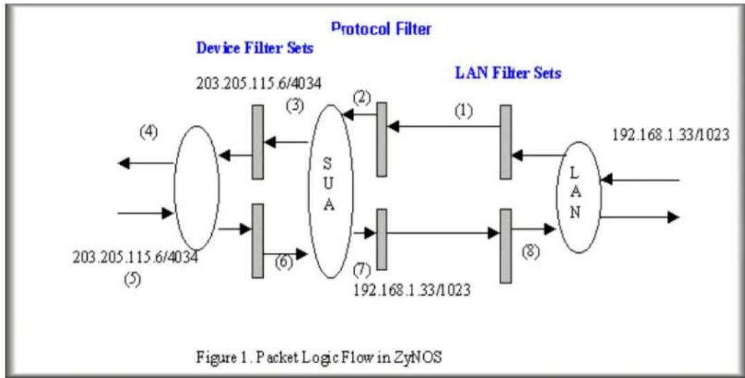
flowchart
graph LR
    subgraph Device Filter Sets
        A["203.205.115.6/4034"] --> B["③"]
        C["203.205.115.6/4034"] --> D["②"]
        E["203.205.115.6/4034"] --> F["⑦"]
        G["203.205.115.6/4034"] --> H["⑥"]
    end
    I["LUAN Filter Sets"] --> J["192.168.1.33/1023"]
    I --> K["LAN"]
    style Device Filter Sets fill:#f9f,stroke:#333
    style LAN Filter Sets fill:#bbf,stroke:#333
Generic and TCP/IP (and IPX) filter rules are in different filter sets. The SMT will detect and prevent the mixing of different category rules within any filter set in Menu 21. In the following example, you will receive an error message 'Protocol and device filter rules cannot be active together' if you try to activate a TCP/IP (or IPX) filter rule in a filter set that has already had one or more active Generic filter rules. You will receive the same error if you try to activate a Generic filter rule in a filter set that has already had one or more active TCP/IP (or IPX) filter rules.
Menu 21.1.1:
Menu 21.1.1 - Generic Filter Rule
Filter #: 1,1
Filter Type= Generic Filter Rule
Active= Yes
Offset= 0
Length= 0
Mask= N/A
Value= N/A
More= No Log= None
Action Matched= Check Next Rule
Action Not Matched= Check Next Rule
Menu 21.1.2:
Menu 21.1.2 - TCP/IP Filter Rule
Filter #: 1,2
Filter Type= TCP/IP Filter Rule
Active= Yes
IP Protocol= 0 IP Source Route= No
Destination: IP Addr= 0.0.0.0
    IP Mask= 0.0.0.0
    Port # = 0
    Port # Comp= None
Source: IP Addr= 0.0.0.0
    IP Mask= 0.0.0.0
    Port # = 0
    Port # Comp= None
TCP Estab= N/A
More= No Log= None
Action Matched= Check Next Rule
Action Not Matched= Check Next Rule

Press ENTER to Confirm or ESC to Cancel:
Saving to ROM. Please wait...
Protocol and device rule cannot be active together
To separate the device and protocol filter categories; two new menus, Menu 11.5 and Menu 13.1, have been added, as well as some changes made to the Menu 3.1, Menu 11.1, and Menu 13. The new fields are shown below.
Menu 3.1:
Menu 3.1 - General Ethernet Setup
Input Filter Sets:
protocol filters=
device filters=
Output Filter Sets:
protocol filters=
device filters=
Menu 11.1:
Menu 11.1 - Remote Node Profile
Rem Node Name= abc
Edit PPP Options= No
Active= Yes
Rem IP Addr=0.0.0.0
Call Direction=Outgoing
Edit IP= No
Incoming:
Rem Login= N/A
Rem Password= N/A
Rem CLID= N/A
Call Back= N/A
Outgoing:
My Login= wxyz
My Password= *****
Authen= CHAP/PAP
Pri Phone #= 140812345678
Sec Phone #= 140822345678
Telco Option:
Transfer Type= 64K
Allocated Budget(min)=
Period(hr)=
Schedules=
Carrier Access Code=
Nailed-Up Connection= No
Toll Period(sec)= 0
Session Options:
Edit Filter Sets= Yes
Idle Timeout(sec)= 100
Press ENTER to Confirm or ESC to Cancel:
Menu 11.5:
Menu 11.5 - Remote Node Filter
Input Filter Sets:
protocol filters=
device filters=
Output Filter Sets:
protocol filters=
device filters=
Call Filter Sets:
protocol filters=
device filters=
Menu 13:
Menu 13 - Default Dial-in Setup
Telco Options: IP Address Supplied By:
CLID Authen= None Dial-in User= Yes
IP Pool= Yes

PPP Options: IP Start Addr= 123.234.111.163
Recv Authen= CHAP/PAP IP Count(1,4)= 4
Compression= Yes

Mutual Authen= No Session Options:
O/G Username= N/A Edit Filter Sets= Yes
O/G Password= N/A

Multiple Link Options:
Max Trans Rate(Kbps)= 128

Callback Budget Management:
Allocated Budget(min)= 0
Period(hr)= 0

Press ENTER to Confirm or ESC to Cancel:
Menu 13.1:
Menu 13.1 - Default Dial-in Filter
Input Filter Sets:
protocol filters=
device filters=
Output Filter Sets:
protocol filters=
device filters=
SMT will also prevent you from entering a protocol filter set configured in Menu 21 to the device filters field in Menu 3.1, 11.5, or 13.1, or entering a device filter set to the protocol filters field. Even though SMT will prevent the inconsistency from being entered in ZyNOS, it is unable to resolve the intermixing problems existing in the filter sets that were configured before. Instead, when ZyNOS translates the old configuration into the new format, it will verify the filter rules and log the inconsistencies. Please check the system log (Menu 24.3.1) before putting your device into use.
Running the P-202H Plus v2 with wrong filter rules may cause it to keep the ISDN line perpetually active, and/or allow undesired traffic to pass to the outside world, and receive unwanted outside traffic. The first case may incur an enormous ISDN bill; the second may lead to a data security hazard.
In order to avoid operational problems later, the P-202H Plus v2 will disable its routing/bridging functions if there is an inconsistency among its filter rules.
How do I know what packet is triggering the call?
If the user already knows the protocol type, the source port and the IP address of the packet that is triggering the call, he can design the filter rule based on these information. Otherwise, he can take a look at the SMT Menu 24.1 to see what is the exact packet that triggers the outgoing call. The 'LAN Packet Which Triggered Last Call' status in Menu 24.1 will show you the packet which triggers the call. A display of the header of the packets is shown next.
LAN Packet which Triggered Last Call: (Type: IP) 45 00 00 2E CA 0E 40 00 1F 06 D7 09 CC F7 CB B4 CC D9 00 02 04 1C 00 15 00 33 2D 5E 55 80 B5 C0 50 18 1F 9B E7 D4 00 00 50 41 53 56 0D 0A
We list the header of the IP, UDP and TCP in order to make you know more about the format of the IP packet and IPX packet in Menu 24.1 for easy configuration of a filter rule.
IP Header
| 0 | 15 |
| 16 | 31 |
| 4-bit version | 4-bit length | 8-bit type of service (TOS) | 16-bit total length (in bytes) | |
| 16-bit identification 3-bit | flag | 13-bit fragment offset | ||
| 8-bit time to live(TTL) | 8-bit protocol 16-bit header checksum | |||
| 32-bit source IP address | ||||
| 32-bit destination IP address | ||||
| Option (if any) | ||||
| Data | ||||
UDP Header
| 0 | 15 |
| 16 | 31 |
| 16-bit source port number 16-bit destination port number | |
| 16-bit UDP length 16-bit UDP checksum | |
| Data (if any) | |
TCP Header
| 0 | 15 |
| 16 | 31 |
| 16-bit source port number 16-bit destination port number | |||||||
| 32-bit sequence number | |||||||
| 32-bit acknowledgment number | |||||||
| 4-bit header length | Reserved (6 bits) | U | A | P | R | S | F |
| R | C | S | S | Y | I | ||
| G | K | H | T | N | N | ||
| 16-bit TCP checksum 16-bit urgent pointer | |||||||
| Option (if any) | |||||||
Data (if any)
Based on the above headers, we can then interpret the LAN Packet Which Triggered Last Call as following:
LAN Packet which Triggered Last Call : (Type: IP) 45 00 00 2E CA 0E 40 00 1F 06 D7 09 CC F7 CB B4 CC D9 00 02 04 1C 00 15
06 = TCP Protocol CC F7 CB B4= 204.247.203.180 = Source IP CC D9 00 02= 204.217.0.2 = Destination IP 04 1C=1052(dec)= Source port number 00 15= 21(dec)=Destination port number = FTP port
IPX header in Menu 24.1:
LAN Packet Which Triggered Last Call: (Type: IPX) 00 28 01 01 00 00 00 00 FF FF FF FF FF FF 04 53 00 00 00 00 00 00 00 00 0004 53 00 01 FF FF FF FF FF FF 00 00 00 00
01 IPX packet type 00 00 00 00 Destination network number FF FF FF FF FF FF Destination node number 04 53 Destination socket number 00 00 00 00 Source network number 00 00 00 00 00 Source node number 04 53 Source socket number
IPX packet type:
01=RIP 02=echo 03=error 04=SAP 05=SPX 11=NCP 14=NetBIOS
Socket number:
0451=NCP 0451=SAP 0453=RIP 0455=NetBIOS
Filter Examples
Filter example
A filter for blocking the FTP connections from WAN
- Introduction
The P-202H Plus v2 supports the firmware and configuration files upload using FTP connections via LAN and WAN. So, it is possible that anyone can make a FTP connection over the Internet to your P-202H Plus v2. To prevent outside users from connecting to your P-202H Plus v2 via FTP, you can configure a filter to block FTP connections from WAN.
- Before you begin
Before configuring a filter, you need to know the following information:
-
The inbound packet type (protocol & port number): In this case, it is TCP(06) protocol with port 20 or 21.
-
The source IP address: In this case, we block all connections from outside so the source IP is 0.0.0.0.
-
The destination IP address: It is the P-202H Plus v2's IP address, but it is not available in SUA case since most WAN IP address is dynamically assigned by the ISP. So, we can only enter 0.0.0.0 as the destination IP in the filter rule. Once 0.0.0.0 is set as the destination IP, no FTP connections are allowed to reach the P-202H Plus v2 nor the FTP server on the LAN. For the LAN-to-LAN connection, you enter the P-202H Plus v2's LAN IP as the destination IP in the filter rule. After the FTP filter is applied to the remote node, it only blocks the FTP connection to the P-202H Plus v2 but still permits the FTP connection to the local FTP server.
- Configuration
○ Create a filter set in Menu 21, e.g., set 3
○ Create two filter rules in Menu 21.3.1 and Menu 21.3.2
- Rule 1- block the inbound FTP packet, TCP (06) protocol with port number 20
- Rule 2- block the inbound FTP packet, TCP (06) protocol with port number 21
- Apply the filter set in remote node, Menu 11
- Create a filter set in Menu 21
Menu 21 - Filter Set Configuration
| Filter Set # | Comments | Filter Set # | Comments |
| 1 | NetBIOS_WAN | 7 | |
| 2 | NetBIOS_LAN | 8 | |
| 3 | FTP_WAN | 9 | |
| 4 | 10 | ||
| 5 | 11 | ||
| 6 | 12 |
Enter Filter Set Number to Configure= 3
Edit Comments= FTP_WAN
Press ENTER to Confirm or ESC to Cancel:
- Rule 1- block the inbound FTP packet, TCP (06) protocol with port number 20
Menu 21.3.1 - TCP/IP Filter Rule
Filter #: 3,1
Filter Type= TCP/IP Filter Rule
Active= Yes
IP Protocol= 6 IP Source Route= No
Destination: IP Addr= 0.0.0.0
    IP Mask= 0.0.0.0
    Port # = 20
    Port # Comp= Equal
Source: IP Addr= 0.0.0.0
    IP Mask= 0.0.0.0
    Port #=
    Port # Comp= None
TCP Estab= No
More= No Log= None
Action Matched= Drop
Action Not Matched= Check Next Rule
Press ENTER to Confirm or ESC to Cancel:
- Rule 2- block the inbound FTP packet, TCP (06) protocol with port number 21
Menu 21.3.2 - TCP/IP Filter Rule
Filter #: 1,2
Filter Type= TCP/IP Filter Rule
Active= Yes
IP Protocol= 6 IP Source Route= No
Destination: IP Addr= 0.0.0.0
    IP Mask= 0.0.0.0
    Port # = 21
    Port # Comp= Equal
Source: IP Addr= 0.0.0.0
    IP Mask= 0.0.0.0
    Port #
    Port # Comp= None
TCP Estab= No
More= No Log= None
Action Matched= Drop
Action Not Matched= Forward
Press ENTER to Confirm or ESC to Can
- When two rules are completed, you can see the rule summary in Menu 21.1
Menu 21.3 - Filter Rules Summary
<h1 id="a-type-filter-rules-m-m-n">A Type    Filter Rules    M m n</h1>
1 Y IP Pr=6, SA=0.0.0.0, DA=0.0.0.0, DP=20    N D N
2 Y IP Pr=6, SA=0.0.0.0, DA=0.0.0.0, DP=21    N D F
3 N
4 N
5 N
6 N
- Choose the remote node number where you want to block the inbound FTP connections and apply the filter set in menu 11.5 by selecting the 'Edit Filter Sets' to 'Yes'.
Menu 11.1 - Remote Node Profile
Rem Node Name= hinet
Active= Yes
Call Direction= Outgoing
Edit PPP Options= No
Rem IP Addr= 0.0.0.0
Edit IP= No
Incoming:
Rem Login= N/A
Rem Password= N/A
Rem CLID= N/A
Call Back= N/A
Outgoing:
My Login= masterbc
My Password= *
Authen= CHAP/PAP
Pri Phone #= 4125678
Sec Phone #=
Telco Option:
Transfer Type= 64K
Allocated Budget(min)=
Period(hr)=
Carrier Access Code=
Nailed-Up Connection= No
Toll Period(sec)= 0
Session Options:
Edit Filter Sets= Yes
Idle Timeout(sec)= 300
Press ENTER to Confirm or ESC to Cancel:
- Put the filter set number '3' to the 'Input Protocol Filter Set' in menu 11.5 for activating the FTP_WAN filter.
Menu 11.5 - Remote Node Filter
Input Filter Sets:
protocol filters= 3
device filters=
Output Filter Sets:
protocol filters=
device filters=
Call Filter Sets:
protocol filters=
device filters=
A filter for blocking the web connections from LAN
- Introduction
If you want to avoid the outbound Web request to trigger a call to the remote web server, you can configure a call filter set in P-202H Plus v2 to block this packet. After the call filter is applied, the Web packet will not triggered the call to your ISP or remote node. However, when the call is trigger by the other packets and the Internet connection is established, the workstations then are able to access the Web page.
- Configuration
Before configuring a filter, you need to know the following information:
- The outbound packet type (protocol & port number)
- The source IP address
Generally, the outbound packets for Web service could be as following:
a. HTTP packet, TCP (06) protocol with port number 80
b. DNS packet, TCP (06) protocol with port number 53 or
c. DNS packet, UDP (17) protocol with port number 53
For all workstation on the LAN, the source IP address will be 0.0.0.0. Otherwise, you have to enter an IP Address for the workstation you want to block. See the procedure for configuring this filter below.
○ Create a filter set in Menu 21, e.g., set 1
○ Create three filter rules in Menu 21.1.1, Menu 21.1.2, Menu 21.1.3
- Rule 1- block the HTTP packet, TCP (06) protocol with port number 80
- Rule 2- block the DNS packet, TCP (06) protocol with port number 53
- Rule 3- block the DNS packet, UDP (17) protocol with port number 53
- Apply the filter set in remote node, Menu 11
- Create a filter set in Menu 21
Menu 21 - Filter Set Configuration
Filter
Set #
Comments
Filter
Set #
Comments
| 1 | Web Request | 7 |
| 2 | 8 | |
| 3 | 9 | |
| 4 | 10 | |
| 5 | 11 | |
| 6 | 12 |
Enter Filter Set Number to Configure= 1
Edit Comments=
Press ENTER to Confirm or ESC to Cancel:
• Rule one for (a). http packet, TCP(06)/Port number 80
Menu 21.1.1 - TCP/IP Filter Rule
Filter #: 1,1
Filter Type= TCP/IP Filter Rule
Active= Yes
IP Protocol= 6 IP Source Route= No
Destination: IP Addr= 0.0.0.0
    IP Mask= 0.0.0.0
    Port # = 80
    Port # Comp= Equal
Source: IP Addr= 0.0.0.0
    IP Mask= 0.0.0.0
    Port #=
    Port # Comp= None
TCP Estab= No
More= No Log= None
Action Matched= Drop
Action Not Matched= Check Next Rule
Press ENTER to Confirm or ESC to Ca
- Rule 2 for (b).DNS request, TCP(06)/Port number 53
Menu 21.1.2 - TCP/IP Filter Rule
Filter #: 1,2
Filter Type= TCP/IP Filter Rule
Active= Yes
IP Protocol= 6 IP Source Route= No
Destination: IP Addr= 0.0.0.0
    IP Mask= 0.0.0.0
    Port # = 53
    Port # Comp= Equal
Source: IP Addr= 0.0.0.0
    IP Mask= 0.0.0.0
    Port #
    Port # Comp= None
TCP Estab= No
More= No Log= None
Action Matched= Drop
Action Not Matched= Check Next Rule

Press ENTER to Confirm or ESC to Ca
• Rule 3 for (c). DNS packet UDP(17)/Port number 53
Menu 21.1.2 - TCP/IP Filter Rule
Filter #: 1,2
Filter Type= TCP/IP Filter Rule
Active= Yes
IP Protocol= 17    IP Source Route= No
Destination: IP Addr= 0.0.0.0
    IP Mask= 0.0.0.0
    Port # = 53
    Port # Comp= Equal
Source: IP Addr= 0.0.0.0
    IP Mask= 0.0.0.0
Port #=
Port # Comp= None
TCP Estab= No
More= No Log= None
Action Matched= Drop
Action Not Matched= Forward
Press ENTER to Confirm or ESC to Cancel:
- After the three rules are completed, you will see the rule summary in Menu 21.
Menu 21.1 - Filter Rules Summary
# A Type Filter Rules M m n
1 Y IP Pr=6, SA=0.0.0.0, DA=0.0.0.0, N D N
2 Y IP Pr=6, SA=0.0.0.0, DA=0.0.0.0, N D N
3 Y IP Pr=17, SA=0.0.0.0, DA=0.0.0.0, N D F
- Then put the filter set number '1' in the 'Call Filter Set' field of SMT menu 11.5 for taking active.
Menu 11.1 - Remote Node Profile
| Rem Node Name= Hinet Active= Yes | Route= IP Bridge= No |
| Call Direction= Outgoing Incoming: Rem Login= N/A Rem Password= N/A Rem CLID= N/A Call Back= N/A Outgoing: My Login= qwer | Edit PPP Options= No Rem IP Addr= 0.0.0.0 Edit IP/IPX/Bridge= No Telco Option: Allocated Budget(min)= 5 Period(hr)= 1 Transfer Type= 64K Nailed-Up Connection= No |
My Password= ***** Session Options:
Authen= CHAP/PAP Edit Filter Sets= Yes
Pri Phone #= 4125678 Idle Timeout(sec)= 300
Sec Phone #=
Press ENTER to Confirm or ESC to Cancel:
Menu 11.5 - Remote Node Filter
Input Filter Sets:
protocol filters=
device filters=
Output Filter Sets:
protocol filters=
device filters=
Call Filter Sets:
protocol filters=1
device filters=
A filter for blocking a specific client
- Introduction
If you want to forbid a specific local client from triggering a call to ISP, you can configure a call filter set in P-202H Plus v2 to block the packets from this client. After the call filter is applied, the packet that is sent from this client would not trigger the call to your ISP or remote node. As long as the call is triggered by the other clients and the Internet connection is established, this workstation will be able to access the Internet or remote node.
- Configuration
- Create a filter set in Menu 21, e.g., set 1
Menu 21 - Filter Set Configuration
| Filter Set # | Comments | Filter Set # | Comments |
| 1 | Block a client | 7 |

Enter Filter Set Number to Configure= 0
Edit Comments=
Press ENTER to Confirm or ESC to Cancel:
- One rule one for blocking all packets from this client
Menu 21.1.1 - TCP/IP Filter Rule
Filter #: 1,1
Filter Type= TCP/IP Filter Rule
Active= Yes
IP Protocol=0 IP Source Route=No
Destination: IP Addr= 0.0.0.0
IP Mask= 0.0.0.0
Port #=
Port # Comp= None
Source: IP Addr= 192.168.1.5
IP Mask= 255.255.255.255
Port #=
Port # Comp= None
TCP Estab= N/A
More= No Log= None
Action Matched= Drop
Action Not Matched= Forward
Press ENTER to Confirm or ESC to Cancel:
Key Settings:
- Source IP addr....Enter the client IP in this field
- IP Mask......here the IP mask is used to mask the bits of the IP address given in the 'Source IP Addr=' field, for one workstation it is 255.255.255.255.
- Action Matched......Set to 'Drop' to drop all the packets from this client
-
Action Not Matched......Set to 'Forward' to allow the packets from other clients
-
Apply the filter set number '1' in the 'Call Filter Set' field of SMT menu 11.5 for taking active.
Menu 11.1 - Remote Node Profile
| Rem Node Name= Hinet Active= Yes | Route= IP Bridge= No |
| Call Direction= Outgoing Incoming: Rem Login= N/A Rem Password= N/A Rem CLID= N/A Call Back= N/A Outgoing: My Login= qwer My Password= ***** Authen= CHAP/PAP Pri Phone #= 4125678 Sec Phone #= | Edit PPP Options= No Rem IP Addr= 0.0.0.0 Edit IP/IPX/Bridge= No Telco Option: Allocated Budget(min)= 5 Period(hr)= 1 Transfer Type= 64K Nailed-Up Connection= No Session Options: Edit Filter Sets= Yes Idle Timeout(sec)= 300 |
Press ENTER to Confirm or ESC to Cancel:
Menu 11.5 - Remote Node Filter
Input Filter Sets:
protocol filters=
device filters=
Output Filter Sets:
protocol filters=
device filters=
Call Filter Sets:
protocol filters= 1
device filters=
- If you want to prevent this client accessing the Internet or remote node, you can apply this filter set to SMT Menu 3.1, the 'protocol filter' in the Input Filter Sets
Menu 3.1 - General Ethernet Setup
Input Filter Sets:
protocol filters=1
device filters=
Output Filter Sets:
protocol filters=
device filters=
After this filter set is applied to this field, the client (192.168.1.5) will not be allowed to access the Internet or remote node any more.
A filter for blocking a specific MAC address
This configuration example will show you how to use a Generic Filter to block a specific MAC address on the LAN.
Before you Begin
Before you configure the filter you need to know the MAC address of the client. The MAC address can be provided by the NICs. If there is the LAN packet passing through the P-202H Plus v2 you can identify the MAC address from the P-202H Plus v2's LAN packet trace. Please look at the following example to know the trace of the LAN packets.
ras> sys trcp channel enet0 bothway
ras> sys trcp sw on
Now a client on the LAN is trying to ping P-202H Plus v2......
ras> sys trcp sw off ras> sys trcp disp
TIME: 37c060 enet0-RECV len:74 call=0
0000: [00 a0 c5 01 23 45] [00 80 c8 4c ea 63] 08 00 45 00
0010: 00 3c eb 0c 00 00 20 01 e3 ea ca 84 9b 5d ca 84
0020: 9b 63 08 00 45 5c 03 00 05 00 61 62 63 64 65 66
0030: 67 68 69 6a 6b 6c 6d 6e 6f 70 71 72 73 74 75 76
0040: 77 61 62 63 64 65 66 67 68 69
TIME: 37c060 enet0-XMIT len:74 call=0 0000: [00 80 c8 4c ea 63] [00 a0 c5 01 23 45] 08 00 45 00 0010: 00 3c 00 07 00 00 fe 01 f0 ef ca 84 9b 63 ca 84 0020: 9b 5d 00 00 4d 5c 03 00 05 00 61 62 63 64 65 66 0030: 67 68 69 6a 6b 6c 6d 6e 6f 70 71 72 73 74 75 76 0040: 77 61 62 63 64 65 66 67 68 69
The detailed format of the Ethernet Version II:
- Ethernet Version II
- Address: 00-80-C8-4C-EA-63 (Source MAC) ----> 00-A0-C5-23-45 (Destination MAC)
- Ethernet II Protocol Type: IP
- Internet Protocol
- Version (MSB 4 bits): 4
- Header length (LSB 4 bits): 5
- Service type: Precd=Routine, Delay=Normal, Thrput=Normal, Reli=Normal
- Total length: 60 (Octets)
- Fragment ID: 60172
- Flags: May be fragmented, Last fragment, Offset=0 (0x00)
- Time to live: 32 seconds/hops
- IP protocol type: ICMP (0x01)
- Checksum: 0xE3EA
- IP address 202.132.155.93 (Source IP address) ----> 202.132.155.99(Destination IP address)
- No option
- Internet Control Message Protocol
- Type: 8 - Echo Request
-
Code: 0
-
Checksum: 0x455C
- Identifier: 768
- Sequence Number: 1280
- Optional Data: (32 bytes)
- Configurations
From the above first trace, we know that a client is trying to ping the P-202H Plus v2 router. And from the second trace, we know that the P-202H Plus v2 router will send a reply to the client accordingly. The following sample filter will utilize the 'Generic Filter Rule' to block the MAC address [00 80 c8 4c ea 63].
- First, from the incoming LAN packet we know that the unwanted source MAC address starts at the 7th Octet
TIME: 37c060 enet0-RECV len:74 call=0
0000: [00 a0 c5 01 23 45] [00 80 c8 4c ea 63] 08 00 45 00
0010: 00 3c eb 0c 00 00 20 01 e3 ea ca 84 9b 5d ca 84
0020: 9b 63 08 00 45 5c 03 00 05 00 61 62 63 64 65 66
0030: 67 68 69 6a 6b 6c 6d 6e 6f 70 71 72 73 74 75 76
0040: 77 61 62 63 64 65 66 67 68 69
- We are now ready to configure the 'Generic Filter Rule' as below.
Menu 21.1.1 - Generic Filter Rule
Filter #: 1,1
Filter Type= Generic Filter Rule
Active= Yes
Offset= 6
Length= 6
Mask= ffffffffffff
Value= 0080c84cea63
More= No Log= None
Action Matched= Drop
Action Not Matched= Forward
Key Settings:
- Filter Type: Set the 'Filter Type' to 'Generic Filter Rule'.
• Active: Turn 'Active' to 'Yes' -
Offset (in bytes): Set to '6' since the source MAC address starts at 7th octets we need to skip the first octets of the destination MAC address.
• Length (in bytes): Set to '6' since MAC address has 6 octets. -
Mask (in hexadecimal): Specify the value that the P-202H Plus v2 will logically qualify (logical AND) the data in the packet. Since the Length is set to 6 octets the Mask for it should be 12 hexadecimal numbers. In this case, we intent to set to 'ffffffff' to mask the incoming source MAC address, [00 80 c8 4c ea 63].
- Value (in hexadecimal): Specify the MAC address [00 80 c8 4c ea 63] that the P-202H Plus v2 should use to compare with the masked packet. If the result from the masked packet matches the 'Value', then the packet is considered matched.
- Action Matched= : Enter the action you want if the masked packet matches the 'Value'. In this case, we will drop it.
- Action Not Matched= : Enter the action you want if the masked packet does not match the 'Value'. In this case, we will forward it. If you want to configure more rules please select 'Check Next Rule' to start configuring the next new rule. However, please note that the 'Filter Type' must be also 'Generic Filter Rule' but not others. Because the Generic and TCP/IP (IPX) filter rules must be in different filter sets.
Menu 21.1.2 - Generic Filter Rule
Filter #: 1,2
Filter Type= Generic Filter Rule
Active= Yes
Offset= 6
Length= 6
Mask= ffffffff
Value= 0080c810234a
More= No Log= None
Action Matched= Drop
Action Not Matched= Forward
You can now apply it to the 'General Ethernet Setup' in Menu 3.1. Please note that the 'Generic Filter' can only be applied to the 'Device Filter' but not the 'Protocol Filter' that is used for configuring the TCPIP and IPX filters.
Menu 3.1 - General Ethernet Setup
Input Filter Sets:
protocol filters=
device filters= 1
Output Filter Sets:
protocol filters= device filters=
A filter for blocking the NetBIOS packets
- Introduction
The NETBIOS packets contain port numbers and need to be blocked in this case. They are port number 137, 138 and 139 with UDP or TCP protocol. In addition, the NETBIOS packet used to look for a remote DNS server can also trigger the call. Therefore, the filter rules should cover the above packets.
- Configuration
The packets which need to be blocked are as following. Please configure two filter sets with 4 and 2 rules respectively based on the following packets in SMT menu 21.
Filter Set 1:
Rule 1-Destination port number 137 with protocol number 6 (TCP)
- Rule 2-Destination port number 137 with protocol number 17 (UDP)
- Rule 3-Destination port number 138 with protocol number 6 (TCP)
- Rule 4-Destination port number 138 with protocol number 17 (UDP)
- Rule 5-Destination port number 139 with protocol number 6 (TCP)
- Rule 6-Destination port number 139 with protocol number 17 (UDP)
Filter Set 2:
- Rule 1-Source port number 137, Destination port number 53 with protocol number 6 (TCP)
- Rule 2-Source port number 137, Destination port number 53 with protocol number 17 (UDP)
Before starting to set the filter rules, please enter a name for each filter set in the 'Comments' field first.
Menu 21 - Filter Set Configuration
Filter
Set #
Comments
Filter
Set #
Comments
| 1 | NetBIOS_WAN | 7 | |
| 2 | NetBIOS_LAN | 8 | |
| 3 | 9 | ||
| 4 | 10 | ||
| 5 | 11 | ||
| 6 | 12 |
Enter Filter Set Number to Configure= 1 Edit Comments= Press ENTER to Confirm or ESC to Cancel:
- Configure the first filter set 'NetBIOS_WAN' by selecting the Filter Set number 1.
Rule 1-Destination port number 137 with protocol number 6 (TCP)
Menu 21.1.1 - TCP/IP Filter Rule
Filter #: 1,1
Filter Type= TCP/IP Filter Rule
Active= Yes
IP Protocol= 6 IP Source Route= No
Destination: IP Addr= 0.0.0.0
    IP Mask= 0.0.0.0
    Port # = 137
    Port # Comp= Equal
Source: IP Addr= 0.0.0.0
    IP Mask= 0.0.0.0
    Port # = 0
    Port # Comp= None
TCP Estab= No
More= No Log= None
Action Matched= Drop
Action Not Matched= Check Next Rule

Press ENTER to Confirm or ESC to Cancel:
Rule 2-Destination port number 137 with protocol number 17 (UDP)
Menu 21.1.2 - TCP/IP Filter Rule
Filter #: 1,2
Filter Type= TCP/IP Filter Rule
Active= Yes
IP Protocol= 17 IP Source Route= No
Destination: IP Addr= 0.0.0.0
    IP Mask= 0.0.0.0
    Port # = 137
    Port # Comp= Equal
Source: IP Addr= 0.0.0.0
    IP Mask= 0.0.0.0
    Port # = 0
    Port # Comp= None
TCP Estab= N/A
More= No Log= None
Action Matched= Drop
Action Not Matched= Check Next Rule

Press ENTER to Confirm or ESC to Cancel:
Rule 3-Destination port number 138 with protocol number 6 (TCP)
Menu 21.1.3 - TCP/IP Filter Rule
Filter #: 1,3
Filter Type= TCP/IP Filter Rule
Active= Yes
IP Protocol= 6 IP Source Route= No
Destination: IP Addr= 0.0.0.0
    IP Mask= 0.0.0.0
    Port # = 138
    Port # Comp= Equal
Source: IP Addr= 0.0.0.0
    IP Mask= 0.0.0.0
    Port # = 0
    Port # Comp= None
TCP Estab= No
More= No Log= None
Action Matched= Drop
Action Not Matched= Check Next Rule
Press ENTER to Confirm or ESC to Cancel:
Rule 4-Destination port number 138 with protocol number 17 (UDP)
Menu 21.1.4 - TCP/IP Filter Rule
Filter #: 1,4
Filter Type= TCP/IP Filter Rule
Active= Yes
IP Protocol= 17 IP Source Route= No
Destination: IP Addr= 0.0.0.0
    IP Mask= 0.0.0.0
    Port # = 138
    Port # Comp= Equal
Source: IP Addr= 0.0.0.0
    IP Mask= 0.0.0.0
    Port # = 0
    Port # Comp= None
TCP Estab= N/A
More= No Log= None
Action Matched= Drop
Action Not Matched= Check Next Rule
Press ENTER to Confirm or ESC to Cancel:
Rule 5-Destination port number 139 with protocol number 6 (TCP)
Menu 21.1.5 - TCP/IP Filter Rule
Filter #: 1,5
Filter Type= TCP/IP Filter Rule
Active= Yes
IP Protocol= 6 IP Source Route= No
Destination: IP Addr= 0.0.0.0
    IP Mask= 0.0.0.0
    Port # = 139
    Port # Comp= Equal
Source: IP Addr= 0.0.0.0
IP Mask= 0.0.0.0
Port # = 0
Port # Comp= None
TCP Estab= No
More= No Log= None
Action Matched= Drop
Action Not Matched= Check Next Rule
Press ENTER to Confirm or ESC to Cancel:
Rule 6-Destination port number 139 with protocol number 17 (UDP)
Menu 21.1.6 - TCP/IP Filter Rule
Filter #: 1,6
Filter Type= TCP/IP Filter Rule
Active= Yes
IP Protocol= 17 IP Source Route= No
Destination: IP Addr= 0.0.0.0
    IP Mask= 0.0.0.0
    Port # = 139
    Port # Comp= Equal
Source: IP Addr= 0.0.0.0
    IP Mask= 0.0.0.0
    Port # = 0
    Port # Comp= None
TCP Estab= N/A
More= No Log= None
Action Matched= Drop
Action Not Matched= Forward
Press ENTER to Confirm or ESC to Cancel:
After the first filter set is finished, you will see the complete rules summary as below.
Menu 21.2 - Filter Rules Summary
| # A Type | Filter Rules | M m n |
| 1 Y IP | Pr=6, SA=0.0.0.0, DA=0.0.0.0, DP=137 | N D N |
| 2 Y IP | Pr=17, SA=0.0.0.0, DA=0.0.0.0, DP=137 | N D N |
| 3 Y IP | Pr=6, SA=0.0.0.0, DA=0.0.0.0, DP=138 | N D N |
| 4 Y IP | Pr=17, SA=0.0.0.0, DA=0.0.0.0, DP=138 | N D N |
| 5 Y IP | Pr=6, SA=0.0.0.0, DA=0.0.0.0, DP=139 | N D N |
| 6 Y IP | Pr=17, SA=0.0.0.0, DA=0.0.0.0, DP=139 | N D F |
Apply the filter set 'NetBIOS_WAN' to the 'Protocol Filter' of the 'Call Filter Sets=' in the remote node setup 11.5 for taking active. You can enter to the menu 11.5 by selecting the 'Edit Filter Sets=' in menu 11.1 to 'Yes'.
Menu 11.1 - Remote Node Profile
| Rem Node Name= hinetActive= Yes | Route= IPBridge= No |
| Call Direction= OutgoingIncoming:Rem Login= N/ARem Password= N/ARem CLID= N/ACall Back= N/AOutgoing:My Login= masterbcMy Password= *****Authen= CHAP/PAPPri Phone #= 4125678Sec Phone #= | Edit PPP Options= NoRem IP Addr= 0.0.0.0Edit IP/IPX/Bridge= NoTelco Option:Allocated Budget(min)= 0Period(hr)= 0Transfer Type= 64KNailed-Up Connection= NoSession Options:Edit Filter Sets= YesIdle Timeout(sec)= 300 |
Menu 11.5 - Remote Node Filter
Input Filter Sets:
protocol filters=
device filters=
Output Filter Sets:
protocol filters=
device filters=
Call Filter Sets:
protocol filters=1
device filters=
- Configure the second filter set 'NetBIOS_LAN' by selecting the Filter Set number 2.
Rule 1-Source port number 137, Destination port number 53 with protocol number 6 (TCP)
Menu 21.2.1 - TCP/IP Filter Rule
Filter #: 2,1
Filter Type= TCP/IP Filter Rule
Active= Yes
IP Protocol= 6 IP Source Route= No
Destination: IP Addr= 0.0.0.0
    IP Mask= 0.0.0.0
    Port # = 53
    Port # Comp= Equal
Source: IP Addr= 0.0.0.0
    IP Mask= 0.0.0.0
    Port # = 137
    Port # Comp= Equal
TCP Estab= No
More= No Log= None
Action Matched= Drop
Action Not Matched= Check Next Rule
Press ENTER to Confirm or ESC to Cancel:
Rule 2-Source port number 137, Destination port number 53 with protocol number 17 (UDP)
Menu 21.2.2 - TCP/IP Filter Rule
Filter #: 2,2
Filter Type= TCP/IP Filter Rule
Active= Yes
IP Protocol= 17 IP Source Route= No
Destination: IP Addr= 0.0.0.0
    IP Mask= 0.0.0.0
    Port # = 53
    Port # Comp= Equal
Source: IP Addr= 0.0.0.0
    IP Mask= 0.0.0.0
    Port # = 137
    Port # Comp= Equal
TCP Estab= N/A
More= No Log= None
Action Matched= Drop
Action Not Matched= Forward

Press ENTER to Confirm or ESC to Cancel:
After the first filter set is finished, you will see the complete rules summary as below.
Menu 21.2 - Filter Rules Summary
# A Type
Filter Rules
Mmn
1 Y IP Pr=6, SA=0.0.0.0, SP=137, DA=0.0.0.0, DP=53 N D N
2 Y IP Pr=17, SA=0.0.0.0, SP=137, DA=0.0.0.0, DP=53 N D F
Please apply this second filter set 'NetBIOS_LAN' in the 'protocol filters=' of the 'Input Filter Sets:' in the Menu 3 for blocking the packets from LAN.
Menu 3.1 - General Ethernet Setup
Input Filter Sets:
protocol filters= 2
device filters=
Output Filter Sets:
protocol filters=
device filters=
6. UNIX syslog Setup
• P-202H Plus v2 Setup
Menu 24.3.2 - System Maintenance - UNIX Syslog and Accounting
UNIX Syslog:
Active= Yes
Syslog IP Address= 192.168.1.33
Log Facility= Local 1
Types:
CDR= No
Packet triggered= No
Filter log= No
PPP log= No
POTS log= No
Firewall log= No
Configuration:
- Active, use the space bar to turn on the syslog option.
- Syslog IP Address, enter the IP address of the UNIX server that you wish to send the syslog.
- Log Facility, use the space bar to toggle between the 7 different local options.
- Types, use the space bar to toggle the logs we are going to record.
- UNIX Setup
- Make sure that your syslogd starts with -r argument.
-r, this option will enable the facility to receive message from the network using an Internet domain socket with the syslog services. The default setting is not enabled.
- Edit the file /etc/syslog.conf by adding the following line at the end of the /etc/syslog.conf file.
local1.* /var/log/zyxel.log
Where /var/log/zyxel.log is the full path of the log file.
- Restart syslogd.
• ZyXEL Syslog Message Format
P-202H Plus v2 sends 5 types of syslog messages to syslogd, they are:
- CDR log
- Packet Triggered log
- Filter log
- PPP log
- POTS log
| CDR | Call Detail Record (CDR) logs all data phone line activity if set to Yes. |
| Packet triggered | The first 48 bytes or octets and protocol type of the triggering packet is sent to the UNIX syslog server when this field is set to Yes. |
| Filter log | No filters are logged when this field is set to No. Filters with the individual filter Log field set to Yes are logged when this field is set to Yes. |
| PPP log | PPP events are logged when this field is set to Yes. |
| POTS log | Voice calls are logged when this field is set to Yes. |
1. CDR log(call messages)
Format:
sdcmdSyslogSend( SYSLOG_CDR, SYSLOG_INFO, String );
String = board xx line xx channel xx, call xx, str
board = the hardware board ID
line = the WAN ID in a board
channel = channel ID within the WAN
call = the call reference number which starts from 1 and increments by 1 for each new call
str = C01 Outgoing Call dev xx ch xx (dev:device No. ch:channel No.)
C01 Incoming Call xxxxBps xxxx (L2TP,xxxx means Remote Call ID)
C01 Incoming Call xxxx (means connected speed) xxxx (means Remote Call ID)
L02 Tunnel Connected(L2TP)
C02 OutCall Connected xxxx (means connected speed) xxxxx (means Remote Call ID)
C02 CLID call refused
L02 Call Terminated
C02 Call Terminated
Example:
Feb 14 16:57:17 192.168.1.1 ZyXEL Communications Corp.: board 0 line 0 channel 0, call 18, C01 Incoming Call 64000 4125678 Feb 14 17:07:18 192.168.1.1 ZyXEL Communications Corp.: board 0 line 0 channel 0, call 18, C02 Call Terminated
2. Packet triggered log
Format:
sdcmdSyslogSend( SYSLOG_PKTTRI, SYSLOG_NOTICE, String ); String = Packet trigger: Protocol=xx Data=xxxxxxxxxx Protocol: (1:IP 2:IPX 3:IPXHC 4:BPDU 5:ATALK 6:IPNG) Data: We will send forty-eight Hex characters to the server
Example:
Jul 19 11:28:39 192.168.102.2 ZyXEL Communications Corp.: Packet Trigger: Protocol=1, Data=4500003c100100001f010004c0a86614ca849a7b08004a5c02000100616263646566676869 Jul 19 11:28:56 192.168.102.2 ZyXEL Communications Corp.: Packet Trigger: Protocol=1, Data=4500002c1b0140001f06b50ec0a86614ca849a7b0427001700195b3e00000000600220008cc
3. Filter log
This message is available when the 'Log' is enabled in the filter rule setting. The message consists of the packet header and the log of the filter rules.
Format:
sdcmdSyslogSend(SYSLOG_FILLOG, SYSLOG_NOTICE, String); String = IP[Src=xx.xx.xx.xx Dst=xx.xx.xx.xx prot spo=xxxx dpo=xxxx]S04>R01mD IP[...] is the packet header and S04>R01mD means filter set 4 (S) and rule 1 (R),
match (m) drop (D).
Src: Source Address
Dst: Destination Address
prot: Protocol (TCP, UDP, ICMP)
spo: Source port
dpo: Destination port
Example:
Jul 19 14:44:09 192.168.1.1 ZyXEL Communications Corp.: IP[Src=202.132.154.1 Dst=192.168.1.33 UDP spo=0035 dpo=05d4]}S03>R01mF
Jul 19 14:44:13 192.168.1.1 ZyXEL Communications Corp.: IP[Src=192.168.1.33 Dst=202.132.154.1 ICMP]}S03>R01mF
4. PPP Log
Format:
sdcmdSyslogSend( SYSLOG_PPPLOG, SYSLOG_NOTICE, String );
String = ppp:Proto Starting / ppp:Proto Opening / ppp:Proto Closing / ppp:Proto Shutdown
Proto = LCP / ATCP / BACP / BCP / CBCP / CCP / CHAP / PAP / IPCP / IPXCP
Example:
Jul 19 11:43:25 192.168.1.1 ZyXEL Communications Corp.: ppp:LCP Starting
Jul 19 11:43:29 192.168.1.1 ZyXEL Communications Corp.: ppp:IPCP Starting
Jul 19 11:43:34 192.168.1.1 ZyXEL Communications Corp.: ppp:CCP Starting
Jul 19 11:43:38 192.168.1.1 ZyXEL Communications Corp.: ppp:BACP Starting
Jul 19 11:43:43 192.168.1.1 ZyXEL Communications Corp.: ppp:IPCP Opening
Jul 19 11:43:51 192.168.1.1 ZyXEL Communications Corp.: ppp:CCP Opening
Jul 19 11:43:55 192.168.1.1 ZyXEL Communications Corp.: ppp:BACP Opening
Jul 19 11:44:00 192.168.1.1 ZyXEL Communications Corp.: ppp:LCP Closing
Jul 19 11:44:05 192.168.1.1 ZyXEL Communications Corp.: ppp:IPCP Closing
Jul 19 11:44:09 192.168.1.1 ZyXEL Communications Corp.: ppp:CCP Closing
Jul 19 11:44:14 192.168.1.1 ZyXEL Communications Corp.: ppp:BACP Closing
5. POTS Log
Format:
sdcmdSyslogSend( SYSLOG_POTSLOG, SYSLOG_NOTICE, String ); String = Call Connect / Disconnect: Dir = xx Remote Call=xxxx Local Call=xxxx Dir = Call Direction 1: Incoming call 2: Outgoing call Remote Call = a string type which represents as the remote call number Local Call = a string type which represents as the my(local) call number
Example:
Jul 19 12:08:25 192.168.1.1 ZyXEL Communications Corp.: Call Connect: Dir=2 Remote Call=5783942 Local Call=1 Jul 19 12:08:29 192.168.1.1 ZyXEL Communications Corp.: Call Disconnect: Dir=2 Remote Call=2453140 Local Call=1
7. ISDN Leased Line Setup
Internet Access via ISDN Leased Line

flowchart
graph LR
    A["User"] --> B["Prestige"]
    B --> C["Internet"]
    B --> D["ISDN Leased Line"]
This configuration illustrates an Internet Access over an ISDN leased line that is installed by the telco.
Key Settings in P-202H Plus v2
- Menu 2 - ISDN Setup
- Menu 4 - Internet Access Setup
Menu 2 - ISDN Setup
Switch Type: DSS-1 B Channel Usage= Leased/Unused
Incoming Phone Numbers: ISDN Data =
Advance Setup = No
B Channel Usage:
- Set to Leased/Unused if you are using one 64K-leased line
- Set to Leased/Leased if you are using one 128K-leased lines
- Set to Leased/Switch if you are using one 64K-leased line and one switch line
The P-202H Plus v2 does not allow two leased lines to connect two different remote nodes. Therefore, if the Leased/Leased is configured in Menu 2, it allows a 128K-leased connection to a remote node or allows MP bundling to a remote node.
Menu 4 - Internet Access Setup
ISP's Name= hinet
Pri Phone #= N/A
Sec Phone #= N/A
My Login= test
My Password= *****
My WAN IP Addr=0.0.0.0
NAT= SUA Only
Address Mapping Set= N/A
Telco Option:
Transfer Type= Leased
Multilink= Off
Idle Timeout= 100
Key Settings:
My Login and My Password are the login information provided by ISP.
- Turn on SUA if you only have a single user Internet account.
- Enter the IP address assigned from ISP for P-202H Plus v2, enter '0.0.0.0' if the IP is dynamically assigned during the PPP connection
- Set the 'Transfer Type' to 'Leased' for the ISDN leased-line connection
After saving this menu, you will be asked if you want to perform an Internet connection test. Select 'Yes' to perform the test. If the test fails, please check again the above settings again.
When you have configured and saved Menu 4, you should see that you have created a remote node in Menu 11. You can perform more advanced configuration options to this remote node in this menu.
LAN-to-LAN Connection via ISDN Leased Line

flowchart
graph LR
    A["•"] --> B["Prestige"]
    C["•"] --> B
    B --> D["ISDN Leased Line"]
    D --> E["Remote Note"]
This configuration illustrates a LAN-to-LAN connection over an ISDN leased line that is subscribed from the telco.
• Key Settings in P-202H Plus v2
- Menu 2 - ISDN Setup
- Menu 11 - Remote Node Setup
Menu 2 - ISDN Setup
Switch Type: DSS-1 B Channel Usage= Leased/Unused
Incoming Phone Numbers: ISDN Data =
Advance Setup = No
B Channel Usage:
- Set to Leased/Unused if you are using one 64K-leased line
- Set to Leased/Leased if you are using one 128K-leased lines
- Set to Leased/Switch if you are using one 64K-leased line and one switch line
The P-202H Plus v2 does not allow two leased lines to connect two different remote nodes. Therefore,
if the Leased/Leased is configured in Menu 2, it allows a 128K-leased connection to a remote node or allows MP bundling to a remote node.
Menu 11.1 - Remote Node Profile
| Rem Node Name= LAN1Active= YesCall Direction= ***** | Edit PPP Options= NoRem IP Addr= 140.113.1.1Edit IP= No |
| Incoming: | Telco Option: |
| Rem Login= | Transfer Type= Leased |
| Rem Password= | Allocated Budget(min)= |
| Rem CLID= N/A | Period(hr)= |
| Call Back= N/A | Schedules= |
| Outgoing: | Carrier Access Code= |
| My Login= test | Nailed-Up Connection= No |
| My Password= ***** | Toll Period(sec)= 0 |
| Authen= CHAP/PAP | Session Options: |
| Pri Phone #= N/A | Edit Filter Sets= No |
| Sec Phone #= N/A | Idle Timeout(sec)= 100 |
Press ENTER to Confirm or ESC to Cancel:
- Set the 'Transfer Type' to 'Leased' for the ISDN leased-line connection
8. Supplemental Service
The P-202H Plus v2 supports the following supplementary phone features on both of its POTS ports.
- Call Waiting
-
Three Way Calling
-
Call Transfer
- Call Forwarding
- Reminder Ring
- Terminal Portability(Suspend/Resume)
- MSN/subaddress
Most supplementary services are not free, please check with your telephone company for the services they offer.
How do I do call waiting/call hold/call retrieve?
- Put your current call on hold and answer the incoming call - after hearing the call waiting tone, press and immediately release the Flash button on your telephone.
- Put your current call on hold and switch to another call - press and immediately release the Flash button on your telephone.
- Hang up your current call before answering the incoming call - hang up the phone and wait for answering the incoming call.
- Hang up the current active call and switch back to the other call - hang up and wait for the phone to ring. Then pick up the phone to return to the other call.
Why doesn't call waiting work as expected?
An incoming caller will receive a busy signal if:
- You have two calls active (one active and one on hold; or both active by using Three-Way Calling).
- You are dialing a number on the B channel the incoming caller is attempting to reach, but have not yet established a connection.
If no action is taken to answer the call (call waiting indicator tone is ignored), the call waiting tones will disappear after about 20 seconds.
How do I do three way calling?
- Press the Flash key to put the existing call on hold and receive a dial tone.
• Dial the third party's phone number. - When you are ready to conference the call together, press the Flash key again to establish a three way conference call.
How do I remove a party from the three-way calling?
Simply press the Flash key. The last call that was added to the conference is dropped.
If you hang up your telephone during a three-way call and the two other callers remain on the line, the ISDN network will do an implicit transfer to directly connect the two remaining callers together.
How do I do call transfer?
Call Transfer allows you to transfer an active call to a third party. This service must be subscribed from your telephone company.
Transferring an active call to a third party:
- Once you have an active call (Caller A), press Flash key to put Caller A on hold and receive a dial tone.
• Dial the third party's phone number (Caller B). - When you are ready to conference the two calls together, press Flash key to a Three-Way Conference call.
- Hang up the phone. The ISDN network does an implicit transfer to directly connect Caller A with Caller B.
How do I blind call transfer?
- Once you have an active call (Caller A), press Flash key to put the existing call on hold and receive a dial tone.
• Dial the third party's phone number (Caller B). - Before Caller B picks up the call, you can transfer the call by pressing the Flash key. The call is automatically transferred.
What is call forwarding and how do I do it?
The call forwarding means the switch will ring another number at a place where you will be when sometime dials your directory number. There are two methods to active call forwarding, either method should work fine and you can use whichever one you are most comfortable.
- The first is exactly the same as on an analog line, i.e., you pick up the handset and dial the access code assign by your telephone company and the number that you want the calls forwarded. Check with your telephone company for this access code.
- The second is with the 'phone flash' commands where you pick up the handset and press the flash key before dialing the following:
| Command Meaning | |
| *20*forward-number# Active CFB (Call Forwarding Busy) | |
| *21*forward-number# Active CFU (Call Forwarding | |
| Unconditional) | |
| *22*forward-number# Active CFNR (Call Forwarding No Reply | |
| #20# | Deactive |
| #21# | Deactive |
| #22# | Deactive |
CFB CFU CFNR
How do I suspend/resume a phone call (terminal portability)?
The Terminal Portability service allows you to suspend a phone call temporarily. You can then resume this call later, at another location if you so wish.
To suspend an active phone call:
- Press the flash key twice.
• Dial *3n*#, where n is any number from 1 to 9.
To resume your phone call:
- Reconnect at a (n) (ISDN) telephone that is linked to the same S/T interface (Network Terminator-1, NT1) where you suspended the call.
- Pick up the handset and press the Flash key
- Dial #3n#, where n is any number from 1 to 9, but should be identical to that used above.
What is reminder ring?
The P-202H Plus v2 sends a single short ring to your telephone every time a call has been forwarded(US switches only).
What is MSN/subaddress and how do I do it?
Depending on your location, you may have Multiple Subscriber Number (MSN) where the telephone company gives you more than one number for your ISDN line. You can assign each number to a different port, e.g., the first number to data calls, the second to A/B adapter 1 and so on.
Or (DSS1) the telephone company may give you only one number, but allow you to assign your own subaddresses to different ports, e.g., subaddress 1 to data calls and 2 to A/B adapter 1.
9. Using NetCAPI
• What is NetCAPI?
The P-202H Plus v2 202H Plus supports the ISDN Device Control Protocol (ISDN-DCP) from RVS-COM. The ISDN-DCP allows a workstation on the LAN to run some CAPI applications. These applications include FAX, Voice, File transfer. Using ISDN-DCP, the P-202H Plus v2 202H Plus behaves as a DCP server which listens for DCP messages on TCP port number 2578 on its LAN port and we call this feature as NetCAPI.
When the P-202H Plus v2 receives a DCP message from a DCP client (running RVS-COM software), the P-202H Plus v2 sends the confirmation message to the client and sends ISDN packets through the BRI port.
When the P-202H Plus v2 receives packets on its BRI port destined for one of the DCP clients, the router formats the packet as a DCP message and sends it to the corresponding client.
• Supported applications
1. G3/G4 FAX transmission
2. Euro File Transfer (EFT)
3. File transfer
4. Autoanswer host mode
5. Telephony
• Supported D-Channel Protocol
NetCAPI is available only for the European ISDN switch type DSS1.
- RVS-COM Setup
To use the NetCAPI function of the P-202H Plus v2 202H Plus for FAX transmission, file transfer and voice, you must install RVS-COM Lite 1.63 or above first.
- P-202H Plus v2 Setup
All NetCAPI related settings are configured in menu 2.1 as shown below.
- Edit the NetCAPI settings by setting the 'Edit NetCAPI Setup' to 'Yes'.
Menu 2 - ISDN Setup
Switch Type: DSS-1
B Channel Usage= Switch/Switch
Incoming Phone Numbers:
ISDN Data = 10000 Subaddress=
A/B Adapter 1 = Subaddress=
A/B Adapter 2 = Subaddress=
Incoming Phone Number Matching= Multiple Subscriber Number (MSN)
Analog Call Routing= N/A
Global Analog Call= N/A
Edit Advanced Setup = No
Edit NetCAPI Setup = Yes
Press ENTER to Confirm or ESC to Cancel:
- Edit NetCAPI related settings in menu 2.1
Menu 2.2 - NetCAPI Setup
Active= Yes
Max Number of Registered Users= 5
Incoming Data Call Number Matching= NetCAPI
Access List:
Start IP End IP Operation
192.168.1.33 192.168.1.36 Both
0.0.0.0 0.0.0.0 None
0.0.0.0 0.0.0.0 None
0.0.0.0 0.0.0.0 None
0.0.0.0 0.0.0.0 None
0.0.0.0 0.0.0.0 None
0.0.0.0 0.0.0.0 None
0.0.0.0 0.0.0.0 None
default None
Press ENTER to Confirm or ESC to Cancel:
Key Settings:
- Active: Set to 'Yes' to enable the NetCAPI.
-
Max. Number of Registered Users: Enter the number of RVS-COM clients for registering in the P-202H Plus v2. The maximum number is 5.
-
Incoming Data Call Matching: This setting helps the P-202H Plus v2 to forward the incoming call correctly by checking the MSN or subaddress that the remote party calls.
-
MSN: When this option is selected, the P-202H Plus v2 checks the MSN called by the remote party. If the MSN matches the one configured in menu 2, ISDN Data Number, the P-202H Plus v2 will answer the call as a data call. If the MSN does not match any MSN in menu 2, the P-202H Plus v2 will answer the call as a CAPI call and forward it to the CAPI client.
- Subaddress: When this option is selected, the P-202H Plus v2 checks the subaddress called by the remote party. If the subaddress matches the one configured in menu 2, ISDN Data Number, the P-202H Plus v2 will answer the call as a data call. If the subaddress does not match any subaddress in menu 2, the P-202H Plus v2 will answer the call as a CAPI call and forward it to the CAPI client.
-
NetCAPI: When this option is selected, the P-202H Plus v2 always answers the call as a CAPI call and forward it to the CAPI client.
-
Access List: Enter the IP range of the valid NetCAPI clients with desired operation direction.
-
Operation=Incoming: this permits the clients in this IP range to only answer calls.
- Operation=Outgoing: this permits the clients in this IP range to only place calls.
- Operation=Both: this permits the clients in this IP range to both place and answer calls.
-
Operation=None: this means no calls for the clients in this IP range are allowed.
-
Start IP: Refers to the first IP address of a group of NetCAPI clients. Each group contains contiguous IP addresses.
- End IP: Refers to the last IP address in a NetCAPI client group.
-
Operation: Call control settings for the NetCAPI users
-
Incoming: When this option is selected, the NetCAPI users have permission to only accept incoming calls.
- Outgoing: When this option is selected, the NetCAPI users have permission to only place outgoing calls.
- Both: When this option is selected, the NetCAPI users have permission for both answering and placing calls.
- None: When this option is selected, no calls are allowed for the NetCAPI users.
- CAPI CI commands
dcp fsm sw [on|off]
To enable/disable the NetCAPI state machine, use the dcp fsm sw [on|off] command.
dcp fsm disp
To display the NetCAPI state machine log, use the dcp fsm disp command. The following example shows the output of the dcp fsm disp command:
ISDN_DCP FSM Log, Entries = 6
Format
TimeStamp Protocol ObjectID State Event Event Handling Function
0:00:03.190 DCP: 0 S:IDLE(01) E:CapREQ (00) Func:DCPIgnore
1:00:03.215 SC : 0 S:IDLE(01) E:STARTREQ (01) Func:DCPSCStartReq
2:00:04.375 SC : 1 S:ACTI(02) E:ENDREQ (02) Func:DCPSCEndReq
3:00:06.545 DCP: 0 S:IDLE(01) E:CapREQ (00) Func:DCPIgnore
4:00:06.555 SC : 0 S:IDLE(01) E:STARTREQ (01) Func:DCPSCStartReq
5:00:07.245 CC : 1 S:IDLE(01) E:LISTENREQ(05) Func:DCPListenReq
dcp fsm clear
To clear the NetCAPI state machine log, use the dcp fsm clear command.
dcp trcp sw on [on|off]
To enable/disable the NetCAPI packet log, use the dcp trcp sw on [on|off] command.
dcp trcp disp
To display the NetCAPI packet log, use the dcp trcp disp command. The following example shows the output of the dcp trcp disp command:
ISDN_DCP Message Log, Entries = 12
Format 1
Time Stamp Object ID MessageNum Parameter Length Message ID
TIME:23043.188 Obj:00000000 MNum:0x0 Len=0000
DCP_CAPABILITY_REQ(0000)
Format2
Time Stamp Object ID MessageNum Parameter Length Message ID
TIME:23043.188 Obj:00000000 MNum:0x0 Len=0025
DCP_CAPABILITY_CONF(0001)
Parameter Part
00 01 03 01 02 03 01 00 00 00 00 01 05 5a 79 58
45 4c 01 00 0e 50 72 65 73 74 69 67 65 20 32 30
dcp trcp clear
To clear the NetCAPI packet log, use the dcp trcp clear command.
dcp status disp
To display the NetCAPI status, use the dcp status disp command.
dcp object [object\_id]
To display the NetCAPI objects, use the dcp object [object_id] commands.
10. Using RADIUS
• What is RADIUS?
A Network Access Server (NAS, e.g., a Router) operates as a client of RADIUS. The RADIUS client is responsible for passing user information to designated RADIUS servers, and then acting on the response which is returned. RADIUS servers are responsible for receiving user connection requests, authenticating the user, and then returning all configuration information necessary for the client to deliver service to the user.
Transactions between the client and RADIUS server are authenticated through the use of a shared secret, which is never sent over the network. In addition, any user passwords are sent encrypted between the client and RADIUS server, to eliminate the possibility that someone snooping on an unsecured network could determine a user's password.
There has been some confusion in the assignment of port numbers for this protocol. The early deployment of RADIUS was done using the erroneously chosen port number 1645, which conflicts with the "datametrics" service. The officially assigned port number for RADIUS is 1812. So, be sure which port your RADIUS server uses before configuring it in the P-202H Plus v2.
[Note]: The P-202H Plus v2 is configured with default port 1645, please reboot the P-202H Plus v2 it is changed to 1812.
- RADIUS Server Setup
- Get Radius application S/W and install it first.
- If the callback feature is required, please add the following ZyXEL proprietary attributes in the 'Dictionary' file which generally locates in the Radius installation folder. Please note, when editing RADIUS files some RADIUS servers do not suggest DOS Editor or Notepad. So, you can try Wordpad instead.
3.
<h1 id="zyxel-proprietary-attributes">Zyxel proprietary attributes</h1>
ATTRIBUTE Zyxel-Callback-Option 192 integer
VALUE Zyxel-Callback-Option None 0
VALUE Zyxel-Callback-Option Optional 1
VALUE Zyxel-Callback-Option Mandatory 2

<h1 id="zyxel-callback-phone-number-source">Zyxel Callback phone number source</h1>
ATTRIBUTE Zyxel-Callback-Phone-Source 193 integer
VALUE Zyxel-Callback-Phone-Source Preconfigured 0
VALUE Zyxel-Callback-Phone-Source User 1
- Enter the RADIUS client IP and the encrypted key in the 'Clients' file. See an example below.
<h1 id="this-file-contains-a-list-of-clients-which-are-allowed-to-make">This file contains a list of clients which are allowed to make</h1>
<h1 id="authentication-requests-and-their-encryption-key">authentication requests and their encryption key.</h1>
<h1 id="the-first-field-is-a-valid-hostname-for-the-client">The first field is a valid hostname for the client.</h1>
<h1 id="the-second-field-separated-by-blanks-or-tabs-is-the-encryption-key">The second field (separated by blanks or tabs) is the encryption key.</h1>
#
#Client Name    Key
#----
#portmaster1    testing123
203.66.113.187    key187
In this example, the new client 203.66.113.187 is the P-202H Plus v2 router. The key 'key187' must be configured in SMT Menu 23.2 later..
- Enter the user profile including username and password in the 'Users' file. See an example below.
<h1 id="example-1-ppp-user-without-callback">Example 1: PPP user without callback.</h1>
#
<h1 id="username-password">Username Password=" "</h1>
#----
ray Password = "12345"
#
<h1 id="example-2-ppp-user-with-callback">Example 2: PPP user with Callback.</h1>
#
<h1 id="username-password-2">Username Password=" "</h1>
#----
test Password = "1234"
Zyxel-Callback-Option = Mandatory,
Zyxel-Callback-Phone-Source = Preconfigured
Callback-Number = "523444"
- Run "RADIUS.EXE -X15" to turn on the RADIUS service.
- P-202H Plus v2 Setup
Menu 23.2 - System Security - External Server
Authentication Server:
Active= Yes
Type= RADIUS
Server Address= 203.66.113.10
Port #= 1645
Key= key187
Key Settings:
- Server Address----Enter the IP address of the RADIUS server. For example, 203.66.113.10.
o Port#----The default RADIUS/UDP port is 1645. Reboot the P-202H Plus v2, if it is changed to 1812. -
Key----The key must be the same with the one configured in the 'Clients' file.
-
Please check there is no duplicate user setting in SMT menu 14 compared to the 'Users' file in step 4.
11. Using CLID Callback
• What is CLID Callback?
CLID stands for Calling Line Identification (i.e., calling parting number) which can be used by the ISDN CPE to call back without answering the call. The phone number used for calling back is captured from the D channel message. So, if your local ISDN switch is able to carry the calling party number, the P-202H Plus v2 can use this phone number to call back to the remote party.
There are two types of callback that the P-202H Plus v2 supports, they are the CLID callback and MS CBCP callback using Dial-Up Networking. Unlike the CLID callback, when using the MS CBCP callback the CPE must answer the first call to get the remote phone number from PPP CBCP negotiation and then call back to the remote party after hanging up the first call. In such a case, the remote party has to pay for the first phone call. While using the CLID callback, the remote party does not have to pay for the first call since the call is not answered. Therefore, you can not use Dial-Up Networking for the CLID callback since it does not support the CLID callback.
When calling back to a remote node the outgoing user information (username and password) are configured in menu 11.1, Remote Node Profile. While calling back to a dial-in user, the outgoing user information are configured in two fields in menu 13, O/G Login and O/G Password.
- Setup the P-202H Plus v2 for calling back to a remote node
- Setup the P-202H Plus v2 for calling back to a dial-in user
- Setup the P-202H Plus v2 for calling back to a remote node
Generally, there are several settings must be checked when using the CLID callback. They are:
- The 'CLID Authentication' setting in menu 13 must be configured as 'Required' or 'Preferred'.
- The 'Remote CLID' setting in menu 11.1 must be entered for the CLID authentication.
- The 'Callback' setting in menu 11.1 must be toggled to 'Yes'.
- The 'Outgoing user information' in menu 11.1 must be entered.
- The 'Outgoing Phone number' in menu 11.1 must be entered.
The following SMT only show the main settings of the CLID callback, you can refer to the user's manual or the support note for the other settings.
- Toggle the 'CLID Authen' option in menu 13 to 'Required'.
Menu 13 - Default Dial-in Setup
Telco Options: IP Address Supplied By:
CLID Authen= Required Dial-in User= Yes
IP Pool= No
PPP Options: IP Start Addr= N/A
Recv Authen= CHAP/PAP IP Count(1,2)= N/A
Compression= Yes
Mutual Authen= No
O/G Login= N/A Session Options:
O/G Password= N/A Edit Filter Sets= No
Multiple Link Options:
Max Trans Rate(Kbps)= 128
Callback Budget Management:
Allocated Budget(min)=
Period(hr)=
Press ENTER to Confirm or ESC to Cancel:
- Create a remote node for a LAN-to-LAN connection using the CLID callback.
Menu 11.1 - Remote Node Profile
| Rem Node Name= LAN1Active= YesCall Direction= Both | Edit PPP Options= NoRem IP Addr= 192.168.2.1Edit IP= No |
| Incoming:Rem Login= testRem Password= ****Rem CLID= 20000Call Back= YesOutgoing:My Login= testMy Password= ****Authen= CHAP/PAPPri Phone #= 20000Sec Phone #= | Telco Option:Transfer Type= 64KAllocated Budget(min)=Period(hr)= Schedules=Nailed-Up Connection= N/AToll Period(sec)= 0Session Options:Edit Filter Sets= NoIdle Timeout(sec)= 300 |
Press ENTER to Confirm or ESC to Cancel:
CLID Settings:
| Option Description | |
| Rem CLID | Enter the remote phone number in this field which will be used for the CLID authentication. If this number does not match the one that the switch carries, the P-202H Plus v2 will drop the line due to the CLID authentication failure. |
| Call Back Toggle | to 'Yes' to turn on the callback function. |
| Outgoing: My Login | Enter the user name given by the remote node. |
| Outgoing: My Enter the password given by the remote node. | |
| Password | |
| Outgoing: Pri Phone # | Enter the phone number of the remote node for calling back. |
- Setup the P-202H Plus v2 for calling back to a dial-in user
Generally, there are several settings must be checked when using the CLID callback. They are:
- The 'CLID Authentication' setting in menu 13 must be configured as 'Required' or 'Preferred'.
- The 'Outgoing user information' in menu 13 must be entered.
- The 'Callback' setting in menu 13 must be toggled to 'Mandatory'.
- The 'Callback Phone number' setting in menu 14.1 must be predefined in menu.
- The 'Remote CLID' setting in menu 14.1 must be entered for the CLID authentication.
The following SMT only show the main settings of the CLID callback, you can refer to the user's manual or the support note for the other settings.
- Toggle the 'CLID Authen' option to 'Required' and enter the 'Outgoing user information' in menu 13..
| Menu 13 - Default Dial-in Setup | |
| Telco Options: | IP Address Supplied By: |
| CLID Authen= Required | Dial-in User= Yes |
| IP Pool= No | |
| PPP Options: | IP Start Addr= N/A |
| Recv Authen= CHAP/PAP | IP Count(1,2)= N/A |
| Compression= Yes | |
| Mutual Authen= No | |
| O/G Login= test | Session Options: |
| O/G Password= **** | Edit Filter Sets= No |
| Multiple Link Options: | |
| Max Trans Rate(Kbps)= 128 | |
| Callback Budget Management: | |
| Allocated Budget(min)= | |
Period(hr)=
Press ENTER to Confirm or ESC to Cancel:
CLID Settings:
| Option Description | |
| CLID Authen | Toggle the 'CLID Authen' option in menu 13 to 'Required'. |
| O/G Login | Enter the user name given by the remote user for the authentication. |
| O/G Password | Enter the password given by the remote user for the authentication. |
- Create a dial-in user profile using the CLID callback.
Menu 14.1 - Edit Dial-in User
User Name= test
Active= Yes
Password= *****
Callback= Mandatory
Phone # Supplied by Caller= No
Callback Phone #= 20000
Rem CLID= 20000
Idle Timeout= 300
CLID Settings:
| Option Description | |
| Call Back Toggle to 'Mandatory' to turn on the callback function. | |
| Callback Phone # | Enter the phone number of the remote user for calling back. |
| Rem CLID | Enter the remote phone number in this field which will be used for the CLID authentication. If this number does not match the one that the switch carries, the P-202H Plus v2 will drop the line due to the CLID authentication failure. |
12. Using SNMP
1. SNMP Overview
The Simple Network Management Protocol (SNMP) is an applications-layer protocol used to exchange the management information between network devices (e.g., routers). By using SNMP, network administrators can more easily manage network performance, find and solve network problems. The SNMP is a member of the TCP/IP protocol suite, it uses the UDP to exchange messages between a management Client and an Agent, residing in a network node.
There are two versions of SNMP: Version 1 and Version 2. ZyXEL supports SNMPv1. Most of the changes introduced in Version 2 increase SNMP's security capabilities. SNMP encompasses three main areas:
- A small set of management operations.
- Definitions of management variables.
- Data representation.
The operations allowed are: Get, GetNext, Set, and Trap. These functions operates on variables that exist in network nodes. Examples of variables include statistic counters, node port status, and so on. All of the SNMP management functions are carried out through these simple operations. No action operations are available, but these can be simulated by the setting of flag variables. For example, to reset a node, a counter variable named 'time to reset' could be set to a value, causing the node to reset after the time had elapsed.
SNMP variables are defined using the OSI Abstract Syntax Notation One (ASN.1). ASN.1 specifies how a variable is encoded in a transmitted data frame; it is very powerful because the encoded data is self-defining. For example, the encoding of a text string includes an indication that the data unit is a string, along with its length and value. ASN.1 is a flexible way of defining protocols, especially for network management protocols where nodes may support different sets of manageable variables.
The net of variables that each node supports is called the Management Information Base (MIB). The MIB is made up of several parts, including the Standard MIB, specified as part of SNMP, and Enterprise Specific MIB, which are defined by different manufacturer for hardware specific management.
The current Internet-standard MIB, MIB-II, is defined in RFC 1213 and contains 171 objects. These objects are grouped by protocol (including TCP, IP, UDP, SNMP, and other categories, including 'system' and 'interface.'
The Internet Management Model is as shown in figure 1. Interactions between the NMS and managed devices can be any of four different types of commands:
1. Reads
Read is used to monitor the managed devices, NMSs read variables that are maintained by the devices.
2. Writes
Write is used to control the managed devices, NMSs write variables that are stored in the managed devices.
3. Traversal operations
NMSs use these operations to determine which variables a managed device supports and to sequentially gather information from variable tables (such as IP routing table) in managed devices.
4. Traps
The managed devices to asynchronously report certain events to NMSs use trap.
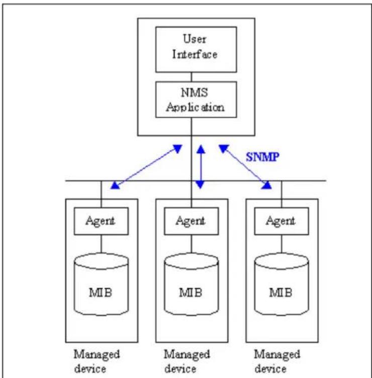
flowchart
graph TD
    A["User Interface"] --> B["NMS Application"]
    B --> C["Managed device"]
    B --> D["Managed device"]
    B --> E["Managed device"]
    C --> F["Agent"]
    D --> G["Agent"]
    E --> H["Agent"]
    F --> I["MIB"]
    G --> J["MIB"]
    H --> K["MIB"]
    B <--> L["SNMP"]
    L <--> C
    L <--> D
    L <--> E
Figure 1: SNMP Management Model
2. SNMPv1 Operations
SNMP itself is a simple request/response protocol. 4 SNMPv1 operations are defined as below.
• Get
Allows the NMS to retrieve an object variable from the agent.
- GetNext
Allows the NMS to retrieve the next object variable from a table or list within an agent. In SNMPv1, when a NMS wants to retrieve all elements of a table from an agent, it initiates a Get operation, followed by a series of GetNext operations.
- Set
Allows the NMS to set values for object variables within an agent.
- Trap
Used by the agent to inform the NMS of some events.
The SNMPv1 messages contains two part. The first part contains a version and a community name. The second part contains the actual SNMP protocol data unit (PDU) specifying the operation to be performed (Get, Set, and so on) and the object values involved in the operation. The following figure shows the SNMPv1 message format.
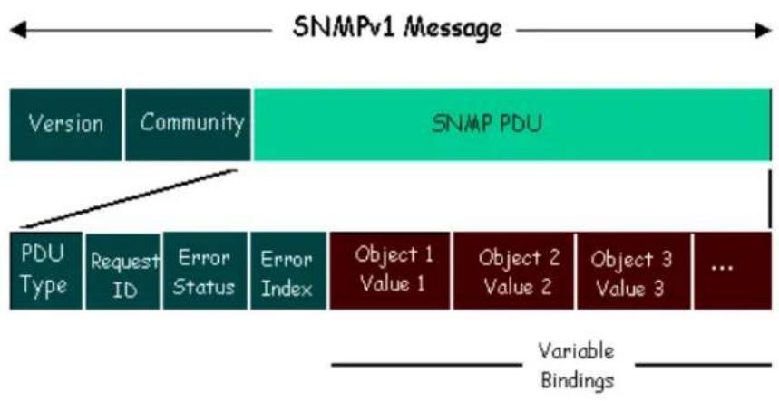
flowchart
graph TD
    A["SNMPv1 Message"] --> B["Version"]
    A --> C["Community"]
    A --> D["SNMP PDU"]
    E["PDU Type"] --> F["Request ID"]
    E --> G["Error Status"]
    E --> H["Error Index"]
    I["Object 1 Value 1"] --> J["Object 2 Value 2"]
    I --> K["Object 3 Value 3"]
    L["..."] --> M["..."]
    N["Variable Bindings"] --> O["..."]
Figure 2: SNMPv1 Message Format
The SNMP PDU contains the following fields:
• PDU type Specifies the type of PDU.
- Request ID Associates requests with responses.
- Error status Indicates an error and an error type.
- Error index Associates the error with a particular object variable.
• Variable-bindings Associates particular object with their value.
2. ZyXEL SNMP Implementation
ZyXEL currently includes SNMP support in some P-202H Plus v2 routers. It is implemented based on the SNMPv1, so it will be able to communicate with SNMPv1 NMSs. Further, users can also add ZyXEL's private MIB in the NMS to monitor and control additional system variables. The ZyXEL's private MIB tree is shown in figure 3. For SNMPv1 operation, ZyXEL permits one community string so that the router can belong to only one community and allows trap messages to be sent to only one NMS manager.
Some traps are sent to the SNMP manager when anyone of the following events happens:
- coldStart (defined in RFC-1215):
If the machine coldstarts, the trap will be sent after booting.
- warmStart (defined in RFC-1215):
If the machine warmstarts, the trap will be sent after booting.
- linkDown (defined in RFC-1215):
If any link of IDSL or WAN is down, the trap will be sent with the port number. The port number is its interface index under the interface group.
- linkUp (defined in RFC-1215):
If any link of IDSL or WAN is up, the trap will be sent with the port number. The port number is its interface index under the interface group.
- authenticationFailure (defined in RFC-1215):
When receiving any SNMP get or set requirement with wrong community, this trap is sent to the manager.
- whyReboot (defined in ZYXEL-MIB):
When the system is going to restart (warmstart), the trap will be sent with the reason of restart before rebooting.
(i) For intentional reboot :
In some cases (download new files, CI command "sys reboot", ...), reboot is done intentionally. And traps with the message "System reboot by user!" will be sent.
(ii) For fatal error :
System has to reboot for some fatal errors. And traps with the message of the fatal code will be sent.
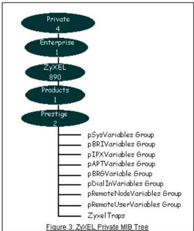
flowchart
graph TD
    A["Private\n4"] --> B["Enterprise\n1"]
    B --> C["ZyxEL\n890"]
    C --> D["Products\n1"]
    D --> E["Prestige\n2"]
    E --> F["pSysVariables Group\npBRIVariables Group\npIPXVariables Group\npAPTVariables Group\npBRGVariable Group\npDialInVariables Group\npRemoteNodeVariables Group\npRemoteUserVariables Group\nZyxel Traps"]
• Downloading ZyXEL's private MIB
3. Configure the P-202H Plus v2 for SNMP
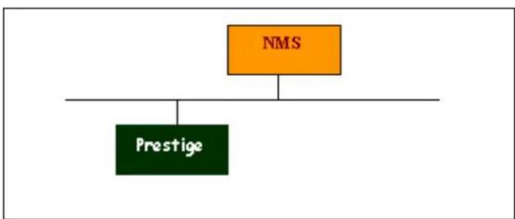
flowchart
graph TD
    A["NMS"] --> B["Prestige"]
The SNMP related settings in P-202H Plus v2 are configured in menu 22, SNMP Configuration. The following steps describe a simple setup procedure for configuring all SNMP settings.
Menu 22 - SNMP Configuration SNMP:
Get Community= public
Set Community= public
Trusted Host= 192.168.1.33
Trap:
Community= public
Destination= 192.168.1.33
Press ENTER to Confirm or ESC to Cancel:
Key Settings:
| Option Descriptions | |
| Get Community | Enter the correct Get Community. This Get Community must match the 'Get-' and 'GetNext' community requested from the NMS. The default is 'public'. |
| Set Community | Enter the correct Set Community. This Set Community must match the 'Set-community requested from the NMS. The default is 'public'. |
| Trusted Host | Enter the IP address of the NMS. The P-202H Plus v2 will only respond to SNMP messages coming from this IP address. If 0.0.0.0 is entered, the P-202H Plus v2 will respond to all NMS managers. |
| Trap Community | Enter the community name in each sent trap to the NMS. This Trap Community must match what the NMS is expecting. The default is 'public'. |
| Trap Destination | Enter the IP address of the NMS that you wish to send the traps to. If 0.0.0.0 is entered, the P-202H Plus v2 will not send trap any NMS manager. |
13. Using Multi-NAT
• What is Multi-NAT?
• How NAT works
- NAT Mapping Types
- SUA Versus NAT
- SMT Menus
-
Applying NAT in the SMT Menus
-
Configuring NAT
- Address Mapping Sets and NAT Server Sets
- NAT Server Sets
- Examples
- Internet Access Only
- Internet Access with an Internal Server
- Using Multiple Global IP addresses for clients and servers
- Support Non NAT Friendly Applications
• What is Multi-NAT?
NAT (Network Address Translation-NAT RFC 1631) is the translation of an Internet Protocol address used within one network to a different IP address known within another network. One network is designated the inside network and the other is the outside. Typically, a company maps its local inside network addresses to one or more global outside IP addresses and "unmaps" the global IP addresses on incoming packets back into local IP addresses. The IP addresses for the NAT can be either fixed or dynamically assigned by the ISP. In addition, you can designate servers, e.g., a web server and a telnet server, on your local network and make them accessible to the outside world. If you do not define any servers, NAT offers the additional benefit of firewall protection. In such case, all incoming connections to your network will be filtered out by the P-202H Plus v2, thus preventing intruders from probing your network.
The SUA feature that the P-202H Plus v2 supports previously operates by mapping the private IP addresses to a global IP address. It is only one subset of the NAT. The ZyNOS V2.41 for the P-202H Plus v2 100IH is enhanced to support the most of the features of the NAT based on RFC 1631, and we call this feature as 'Multi-NAT'. For more information on IP address translation, please refer to RFC 1631, The IP Network Address Translator (NAT).
- How NAT works
If we define the local IP addresses as the Internal Local Addresses (ILA) and the global IP addresses as the Inside Global Address (IGA), see the following figure. The term "inside" refers to the set of networks that are subject to translation. NAT operates by mapping the ILA to the IGA required for communication with hosts on other networks. It replaces the original IP source address (and TCP or UDP source port numbers) and then forwards each packet to the Internet ISP, thus making them appear as if they had come from the NAT system itself (e.g., the P-202H Plus v2 router). The P-202H Plus v2 keeps track of the original addresses and port numbers so incoming reply packets can have their original values restored.
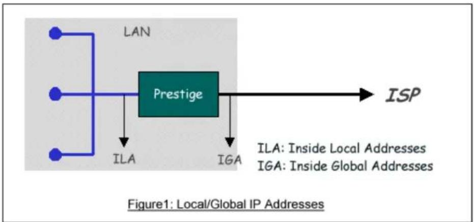
flowchart
graph TD
    A["LAN"] --> B["Prestige"]
    C["ILA"] --> B
    D["IGA"] --> B
    B --> E["ISP"]
- NAT Mapping Types
NAT supports five types of IP/port mapping. They are:
- One to One
In One-to-One mode, the P-202H Plus v2 maps one ILA to one IGA.
- Many to One
In Many-to-One mode, the P-202H Plus v2 maps multiple ILA to one IGA. This is equivalent to SUA (i.e., PAT, port address translation), ZyXEL's Single User Account feature that previous ZyNOS routers supported (the SUA only option in today's routers).
- Many to Many Overload
In Many-to-Many Overload mode, the P-202H Plus v2 maps the multiple ILA to shared IGA.
- Many to Many No Overload
In Many-to-Many No Overload mode, the P-202H Plus v2 maps each ILA to unique IGA.
- Server
In Server mode, the P-202H Plus v2 maps multiple inside servers to one global IP address. This allows us to specify multiple servers of different types behind the NAT for outside access. Note, if you want to map each server to one unique IGA please use the One-to-One mode.
The following table summarizes these types.
| NAT Type IP Mapping | |
| One-to-One | ILA1<---->IGA1 |
| Many-to-One (SUA/PAT) | ILA1<---->IGA1ILA2<---->IGA1... |
| Many-to-Many | ILA1<---->IGA1 |
| Overload | ILA2<---->IGA2ILA3<---->IGA1ILA4<---->IGA2... |
| Many-to-ManyNo Overload | ILA1<---->IGA1ILA2<---->IGA3ILA3<---->IGA2ILA4<---->IGA4... |
| Server | Server 1 IP<---->IGA1Server 2 IP<---->IGA1 |
- SUA Versus NAT
SUA (Single User Account) in previous ZyNOS versions is a NAT set with 2 rules, Many-to-One and Server. The P-202H Plus v2 now has Full Feature NAT support to map global IP addresses to local IP addresses of clients or servers. With multiple global IP addresses, multiple severs of the same type (e.g., FTP servers) are allowed on the LAN for outside access. In previous ZyNOS versions (that supported SUA 'visible' servers had to be of different types. The P-202H Plus v2 supports NAT sets on a remote node basis. They are reusable, but only one set is allowed for each remote node. The P-202H Plus v2 312 supports 2 sets since there is only one remote node. The default SUA (Read Only) Set in menu 15.1 is a convenient, pre-configured, read only, Many-to-One mapping set, sufficient for most purposes and helpful to people already familiar with SUA in previous ZyNOS versions.
- SMT Menus
- Applying NAT in the SMT Menus
- Configuring NAT
- Address Mapping Sets and NAT Server Sets
1. Applying NAT in the SMT Menus
You apply NAT via menus 4 and 11.3 as displayed next. The next figure how you apply NAT for Internet access in menu 4. Enter 4 from the Main Menu to go to Menu 4-Internet Access Setup.
Menu 4 - Internet Access Setup
ISP's Name= ChangeMe
Pri Phone #= 1234
Sec Phone #=
My Login= ChangeMe
My Password= *****
My WAN IP Addr=0.0.0.0
NAT= SUA Only
Address Mapping Set= N/A
Telco Options:
Transfer Type= 64K
Multilink= Off
Idle Timeout= 100
Press ENTER to Confirm or ESC to Cancel:
The following figure shows how you apply NAT to the remote node in menu 11.1.
Menu 11.3 - Remote Node Network Layer Options
Rem IP Addr: 0.0.0.0
Rem Subnet Mask=0.0.0.0
My WAN Addr=0.0.0.0
NAT= SUA Only
Address Mapping Set= N/A
Metric= 2
Private= No
RIP Direction= Both
Version= RIP-2B
Press ENTER to Confirm or ESC to Cancel:
Step 1. Enter 11 from the Main Menu.
Step 2. Move the cursor to the Edit IP field, press the [SPACEBAR] to toggle the
default NO to Yes, then press [ENTER] to bring up Menu 11.3-Remote Node Network Layer Options.
The following table describes the options for Network Address Translation.
| Field | Options | Description |
| Network Address Translation | Full Feature | When you select this option the SMT will use Address Mapping Set 1 (Menu 15.1-see later for further discussion). |
| None | NAT is disabled when you select this option. | |
| SUA Only | When you select this option the SMT will use Address Mapping Set 255 (Menu 15.1-see later for further discussion). This option us basically Many-to-One Overload mapping. Select Full Feature when you require other mapping types. It is a convenient, pre-configured, read only, Many-to-One mapping set, sufficient for most purposes and helpful to people already familiar with SUA in previous ZyNOS versions. Note that there is also a Server type whose IGA is 0.0.0.0 in this set. |
Table: Applying NAT in Menu 4 and Menu 11.3
2. Configuring NAT
To configure NAT, enter 15 from the Main Menu to bring up the following screen.
Menu 15 - NAT Setup
- Address Mapping Sets
- NAT Server Sets
3. Address Mapping Sets and NAT Server Sets
Use the Address Mapping Sets menus and submenus to create the mapping table used to assign global addresses to LAN clients. Each remote node must specify which NAT Address Mapping Set to use. The P312 has one remote node and so allows you to configure only 1 NAT Address Mapping Set. You can see two NAT Address Mapping sets in Menu 15.1. You can only configure Set 1. Set 255 is used for SUA. When you select Full Feature in menu 4 or 11.3, the SMT will use Set1. When you select SUA Only, the SMT will use Set 255. For the P100IH, there are 8 remote nodes and so allows you to configure 8 NAT Address Mapping Sets.
The NAT Server Set is a list of LAN side servers mapped to external ports. To use this set (one set for the P312), a server rule must be set up inside the NAT Address Mapping set. Please see NAT Server Sets for further information on these menus.
Enter 1 to bring up Menu 15.1-Address Mapping Sets
Menu 15.1 - Address Mapping Sets
1.
2.
3.
4.
5.
6.
7.
8.
- SUA (Read Only)
Enter Set Number to Edit:
Let's first look at Option 255. Option 255 is equivalent to SUA in previous ZyXEL routers. The fields in this menu cannot be changed. Entering 255 brings up this screen.
Menu 15.1.255 - Address Mapping Rules
Set Name= SUA (Read Only)
| Idx | Local Start IP | Local End IP | Global Start IP | Global End IP | Type |
| 1. | 0.0.0.0 | 255.255.255.255 | 0.0.0.0 | M-1 | |
| 2. | Server Set= 1 | 0.0.0.0 | Server | ||
| 3. | |||||
| 4. | |||||
| 5. | |||||
| 6. | |||||
| 7. | |||||
| 8. | |||||
| 9. | |||||
| 10. | |||||
| Press ESC or RETURN to Exit: | |||||
The following table explains the fields in this screen. Please note that the fields in this menu are read-only. The Type, Local and Global Start/End IPs are normally (not for this read-only menu) configured in Menu 15.1.1.1 (described later) and the values are displayed here.
| Field | Description | Option/Example |
| Set Name | This is the name of the set you selected in Menu 15.1 or enter the name of a new set you want to create. | SUA |
| Idx This is | the index or rule number. 1 | |
| Local Start IP | This is the starting local IP address (ILA). | 0.0.0.0 for the Many-to-One type.Server Set = 1 for the Server type. |
| Local End IP | This is the starting local IP address (ILA). If the rule is for all local IPs, then the Start IP is 0.0.0.0 and the End IP is 255.255.255.255. | 255.255.255.255 |
| Global Start IP | This is the starting global IP address (IGA). If you have a dynamic IP, enter 0.0.0.0 as the Global Start IP. | 0.0.0.0 |
| Global End IP | This is the ending global IP address (IGA). N/A | |
| Type This is the NAT mapping types. | Many-to-One and Server | |
Please note that the fields in this menu are read-only. However, the settings of the server set 1 can be modified in menu 15.2.1.
Now let's look at Option 1 in Menu 15.1. Enter 1 to bring up this menu.
| Menu 15.1.1 - Address Mapping Rules | ||||||
| Set Name= ? | ||||||
| Idx | Local Start IP | Local End IP | Global Start IP | Global End IP | Type | |
| 1. | ||||||
| 2. | ||||||
| 3. | ||||||
| 4. | ||||||
| 5. | ||||||
| 6. | ||||||
| 7. | ||||||
| 8. | ||||||
| 9. | ||||||
| 10. | ||||||
| Action= Edit , Select Rule= 0 | ||||||
| Press ENTER to Confirm or ESC to Cancel: | ||||||
We will just look at the differences from the previous menu. Note that, this screen is not read only, so we have extra Action and Select Rule fields. Not also that the [?] in the Set Name field means that this is a required field and you must enter a name for the set. The description of the other fields is as described above. The Type, Local and Global Start/End IPs are configured in Menu 15.1.1 (described later) and the values are displayed here.
| Field | Description | Option |
| Set Name | Enter a name for this set of rules. This is a required field.Please note that if this field is left blank, the entire set will be deleted. | Rule1 |
| Action | They are 4 actions. The default is Edit. Edit means you want to edit a selected rule (see following field). Insert Before means to insert a new rule before the rule selected. The rule after the selected rule will then be moved down by one rule. Delete means to delete theselected rule and then all the rules after the selected one will be advanced one rule.Save Set means to save the whole set (note when you choose this action the Select Rule item will be disabled). | EditInsert BeforeDeleteSave Set |
| Select Rule | When you choose Edit, Insert Before or Save Set in the previous field the cursor jumps to this field to allow you to select the rule to apply the action in question. | 1 |
Note: Save Set in the Action field means to save the whole set. You must do this if you make any changes to the set-including deleting a rule. No changes to the set take place until this action is taken. Be careful when ordering your rules as each rule is executed in turn beginning from the first rule.
Selecting Edit in the Action field and then selecting a rule brings up the following menu, Menu 15.1.1.1-Address Mapping Rule in which you can edit an individual rule and configure the Type, Local and Global Start/End IPs displayed in Menu 15.1.1.
Menu 15.1.1.1 - - Rule 1
Type: One-to-One
Local IP:
Start= 0.0.0.0
End = N/A
Global IP:
Start= 0.0.0.0
End = N/A
Server Mapping Set= N/A
Press ENTER to Confirm or ESC to Cancel:
The following table describes the fields in this screen.
| Field | Description | Option/Example | |
| Type | Press [SPACEBAR] to toggle through a total of 5 types. These are the mapping types discussed above plus a server type. Some examples follow to clarify these a little more. | One-to-One Many-to-One Many-to-Many Overload | |
| Many-to-Many No Overload Server | |||
| Local IP | Start | This is the starting local IP address (ILA) 0.0.0.0 | |
| End | This is the ending local IP address (ILA). If the rule is for all local IPs, then put the Start IP as 0.0.0.0 and the End IP as 255.255.255.255.This field is N/A for One-to-One type. | 255.255.255.255 | |
| Global IP | Start | This is the starting global IP address (IGA). If you have a dynamic IP, enter 0.0.0.0 as the Global Start IP. | 0.0.0.0 |
| End | This is the ending global IP address (IGA). This field is N/A for One-to-One, Many-to-One and Server types. | 172.16.23.55 | |
| Local and Global IP fields are N/A for the Server Type. | |||
Note: For all Local and Global IPs, the End IP address must begin after the IP Start address, i.e., you cannot have an End IP address beginning before the Start IP address.
- NAT Server Sets
The NAT Server Set is a list of LAN side servers mapped to external ports (similar to the old SUA menu of before). If you wish, you can make inside servers for different services, e.g., Web or FTP, visible to the outside users, even though NAT makes your network appears as a single machine to the outside world. A server is identified by the port number, e.g., Web service is on port 80 and FTP on port 21.
As an example (see the following figure), if you have a Web server at 192.168.1.36 and a FTP server at 192.168.1.33, then you need to specify for port 80 (Web) the server at IP address 192.168.1.36 and for port 21 (FTP) another at IP address 192.168.1.33.
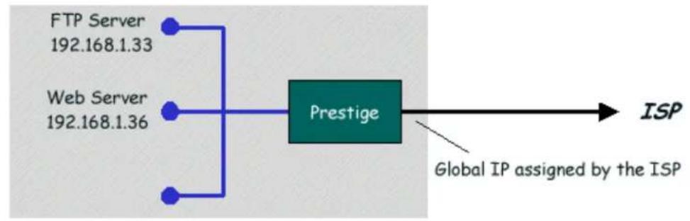
flowchart
graph LR
    A["FTP Server 192.168.1.33"] --> C["Prestige"]
    B["Web Server 192.168.1.36"] --> C["Prestige"]
    D["Global IP assigned by the ISP"] --> E["ISP"]
Figure: Configure Multiple Servers behind NAT
Please note that a server can support more than one service, e.g., a server can provide both FTP and Mail service, while another provides only Web service.
The following procedures show how to configure a server behind NAT.
Step 1. Enter 15 in the Main Menu to go to Menu 15-NAT Setup.
Step 2. Enter 2 to go to Menu 15.2-NAT Server Setup.
Step 3. Enter the service port number in the Port# field and the inside IP address of the server in the IP Address field.
Step 4. Press [SPACEBAR] at the 'Press ENTER to confirm...' prompt to save your configuration after you define all the servers or press ESC at any time to cancel.
Menu 15.2 - NAT Server Setup (Used for SUA Only)
Rule Start Port No. End Port No. IP Address
| 1. | Default | Default | 0.0.0.0 |
| 2. | 80 | 80 | 192.168.1.10 |
| 3. | 21 | 21 | 192.168.1.11 |
| 4. | 0 | 0 | 0.0.0.0 |
| 5. | 0 | 0 | 0.0.0.0 |
| 6. | 0 | 0 | 0.0.0.0 |
| 7. | 0 | 0 | 0.0.0.0 |
| 8. | 0 | 0 | 0.0.0.0 |
| 9. | 0 | 0 | 0.0.0.0 |
| 10. | 0 | 0 | 0.0.0.0 |
| 11. | 0 | 0 | 0.0.0.0 |
- 0 0 0.0.0.0
Press ENTER to Confirm or ESC to Cancel:
The most often used port numbers are shown in the following table. Please refer RFC 1700 for further information about port numbers.
| Service Port Number | |
| FTP | 21 |
| Telnet | 23 |
| SMTP | 25 |
| DNS (Domain Name Server) 53 | |
| www-http (Web) 80 | |
| PPTP (Point-to-Point Tunneling Protocol) | 1723 |
- Examples
- Internet Access Only
- Internet Access with an Internal Server
- Using Multiple Global IP addresses for clients and servers
- Support Non NAT Friendly Applications
1. Internet Access Only
In our Internet Access example, we only need one rule where all our ILAs map to one IGA assigned by the ISP. See the following figure.
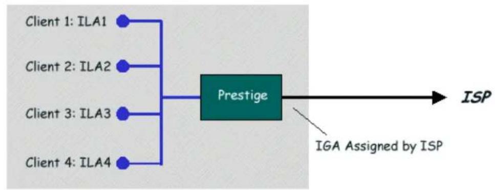
flowchart
graph LR
    A["Client 1: ILA1"] --> C["Prestige"]
    B["Client 2: ILA2"] --> C
    D["Client 3: ILA3"] --> C
    E["Client 4: ILA4"] --> C
    C --> F["ISP"]
    G["IGA Assigned by ISP"] --> F
Internet Access Using NAT Many-to-One Mapping
Menu 4 - Internet Access Setup
ISP's Name= ChangeMe
Pri Phone #= 1234
Sec Phone #=
My Login= ChangeMe
My Password= *****
My WAN IP Addr=0.0.0.0
NAT= SUA Only
Address Mapping Set= N/A
Telco Options:
Transfer Type= 64K
Multilink= Off
Idle Timeout= 100
Press ENTER to Confirm or ESC to Cancel:
From Menu 4 shown above simply choose the SUA Only option from the NAT field. This is the Many-to-One mapping discussed earlier. The SUA read only option from the NAT field in menu 4 and 11.3 is specifically pre-configured to handle this case.
2. Internet Access with an Internal Server
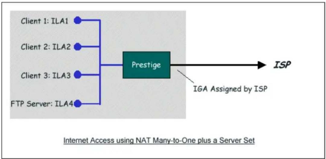
flowchart
graph LR
    A["Client 1: ILA1"] --> C["Prestige"]
    B["Client 2: ILA2"] --> C
    D["Client 3: ILA3"] --> C
    E["FTP Server: ILA4"] --> C
    C --> F["ISP"]
    G["IGA Assigned by ISP"] --> F
    style C fill:#99ccff,stroke:#333
In this case, we do exactly as above (use the convenient pre-configured SUA Only set) and also go to Menu 15.2.1-NAT Server Setup (Used for SUA Only) to specify the Internet Server behind the NAT as shown in the NAT as shown below.
Menu 15.2 - NAT Server Setup (Used for SUA Only)
Rule Start Port No. End Port No. IP Address
| 1. | Default | Default | 0.0.0.0 |
| 2. | 80 | 80 | 192.168.1.33 |
| 3. | 0 | 0 | 0.0.0.0 |
| 4. | 0 | 0 | 0.0.0.0 |
| 5. | 0 | 0 | 0.0.0.0 |
| 6. | 0 | 0 | 0.0.0.0 |
| 7. | 0 | 0 | 0.0.0.0 |
| 8. | 0 | 0 | 0.0.0.0 |
| 9. | 0 | 0 | 0.0.0.0 |
| 10. | 0 | 0 | 0.0.0.0 |
| 11. | 0 | 0 | 0.0.0.0 |
| 12. | 0 | 0 | 0.0.0.0 |
Press ENTER to Confirm or ESC to Cancel:
3. Using Multiple Global IP addresses for clients and servers (One-to-One, Many-to-One, Server Set mapping types are used)
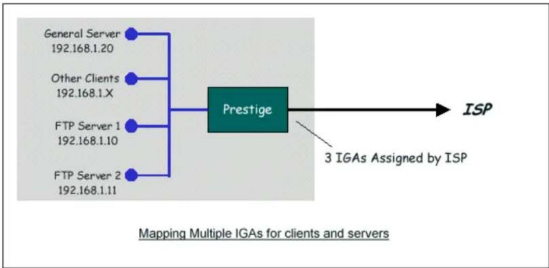
flowchart
graph TD
    A["General Server\n192.168.1.20"] --> C["Prestige"]
    B["Other Clients\n192.168.1.X"] --> C
    D["FTP Server 1\n192.168.1.10"] --> C
    E["FTP Server 2\n192.168.1.11"] --> C
    C --> F["ISP"]
    C --> G["3 IGAs Assigned by ISP"]
    style C fill:#4CAF50,stroke:#388E3C
    note bottom
        Mapping Multiple IGAs for clients and servers
    end
In this case we have 3 IGAs (IGA1, IGA2 and IGA3) from the ISP. We have two very busy internal FTP servers and also an internal general server for the web and mail. In this case, we want to assign the 3 IGAs by the following way using 4 NAT rules.
- Rule 1 (One-to-One type) to map the FTP Server 1 with ILA1 (192.168.1.10) to IGA1.
- Rule 2 (One-to-One type) to map the FTP Server 2 with ILA2 (192.168.1.11) to IGA2.
- Rule 3 (Many-to-One type) to map the other clients to IGA3.
- Rule 4 (Server type) to map a web server and mail server with ILA3 (192.168.1.20) to IGA3. Type Server allows us to specify multiple servers, of different types, to other machines behind NAT on the LAN.
Step 1:
In this case, we need to configure Address Mapping Set 1 from Menu 15.1-Address Mapping Sets. Therefore we must choose the Full Feature option from the NAT field in menu 4 or menu 11.3.
Menu 4 - Internet Access Setup
ISP's Name= ChangeMe
Pri Phone #= 1234
Sec Phone #=
My Login= ChangeMe
My Password= *****
My WAN IP Addr=0.0.0.0
NAT= Full Feature
Address Mapping Set= N/A
Telco Options:
Transfer Type= 64K
Multilink= Off
Idle Timeout= 100
Press ENTER to Confirm or ESC to Cancel:
Step 2:
Go to menu 15.1 and choose 1 (not 255, SUA this time) to begin configuring this new set. Enter a Set Name, choose the Edit Action and then select 1 from Select Rule field. Press [ENTER] to confirm. See the following setup for the four rules in our case.
Rule 1 Setup: Select One-to-One type to map the FTP Server 1 with ILA1 (192.168.1.10) to IGA1.
Press ENTER to Confirm or ESC to Cancel:
Rule 2 Setup: Selecting One-to-One type to map the FTP Server 2 with ILA2 (192.168.1.11) to IGA2.
Press ENTER to Confirm or ESC to Cancel:
Rule 3 Setup: Select Many-to-One type to map the other clients to IGA3.
End = 255.255.255.255
Global IP:
Start= [Enter IGA3]
End = N/A
Press ENTER to Confirm or ESC to Cancel:
Rule 4 Setup: Select Server type to map our web server and mail server with ILA3 (192.168.1.20) to IGA3.
Menu 15.1.1.4 - - Rule 4
Type: Server
Local IP:
Start= N/A
End = N/A
Global IP:
Start=[Enter IGA3]
End = N/A
Press ENTER to Confirm or ESC to Cancel:
When we have configured all four rules Menu 15.1.1 should look as follows.
Menu 15.1.1 - Address Mapping Rules
Set Name= Example3
Idx Local Start IP Local End IP Global Start IP Global End IP Type
- 192.168.1.10
[IGA1]
1-1
- 192.168.1.11
[IGA2]
1-1
- 0.0.0.0 255.255.255.255 [IGA3]
M-1
- Server Set=2
[IGA3]
Server
5.
6.
7.
8.
9.
10.
Press ESC or RETURN to Exit:
Step 3:
Now we configure all other incoming traffic to go to our web server aand mail server from Menu 15.2.2 - NAT Server Setup (not Set 1, Set 1 is used for SUA Only case).
Menu 15.2 - NAT Server Setup (Used for SUA Only)
Rule Start Port No. End Port No. IP Address
| 1. | Default | Default | 0.0.0.0 |
| 2. | 80 | 80 | 192.168.1.10 |
| 3. | 25 | 25 | 192.168.1.11 |
| 4. | 0 | 0 | 0.0.0.0 |
| 5. | 0 | 0 | 0.0.0.0 |
| 6. | 0 | 0 | 0.0.0.0 |
| 7. | 0 | 0 | 0.0.0.0 |
| 8. | 0 | 0 | 0.0.0.0 |
| 9. | 0 | 0 | 0.0.0.0 |
| 10. | 0 | 0 | 0.0.0.0 |
| 11. | 0 | 0 | 0.0.0.0 |
| 12. | 0 | 0 | 0.0.0.0 |
Press ENTER to Confirm or ESC to Cancel:
4. Support Non NAT Friendly Applications
Some servers providing Internet applications such as some mIRC servers do not allow users to login using the same IP address. In this case it is better to use Many-to-Many No Overload or One-to-One NAT mapping types, thus each user login to the server using a unique global IP address. The following figure illustrates this.
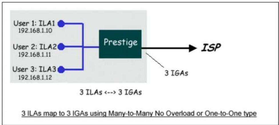
flowchart
graph LR
    A["User 1: ILA1\n192.168.1.10"] --> C["Prestige"]
    B["User 2: ILA2\n192.168.1.11"] --> C
    D["User 3: ILA3\n192.168.1.12"] --> C
    C --> E["ISP"]
    F["3 IGAs"] --> C
    style C fill:#4CAF50,stroke:#333
    note right of C
        3 ILAs <--> 3 IGAs
    end
One rule configured for using Many-to-Many No Overload mapping type is shown below.
Type: Many-to-Many No Overload
Local IP:
Start= 192.168.1.10
End = 192.168.1.12
Global IP:
Start= [Enter IGA1]
End = [Enter IGA3]
Press ENTER to Confirm or ESC to Cancel:
The three rules configured for using One-to-One mapping type is shown below.
Press ENTER to Confirm or ESC to Cancel:
Press ENTER to Confirm or ESC to Cancel:
Global IP:
Start= [Enter IGA3]
End = N/A
Press ENTER to Confirm or ESC to Cancel:
IPSec VPN
1. Using IPSec VPN
What is IPSec?
IPSec is a set of IP extensions developed by IETF (Internet Engineering Task Force) to provide security services compatible with the existing IP standard (IPv.4) and also the upcoming one(IPv.6). In addition, IPSec can protect any protocol that runs on top of IP, for instance TCP, UDP, and ICMP. IPSec is truly the most extensible and complete network security solution.
IPSec which is based on modern cryptographic technologies enables end-to-end security so that every single piece of information sent to or from a computer can be secured. It can also be deployed inside a network to form Virtual Private Networks (VPNs) where two distincts and disparate networks become one by connecting them with a tunnel secured by IPSec.
Tunnel mode
IPSec in tunnel mode is normally used when the ultimate destination of the packet is different from the security termination point. We introduce two tunnel mode examples:
• Secure Gateway to Secure Gateway
P-202H Plus v2 to P-202H Plus v2 Tunneling
- Setup P-202H Plus v2 A
- Setup P-202H Plus v2 B
- Troubleshooting
- View Log
This page guides us to setup a VPN connection between two P-202H Plus v2 routers. Please note that, in addition to P-202H Plus v2 to P-202H Plus v2, P-202H Plus v2 can also talk to other VPN hardwards. The tested VPN hardware are shown below.
• Cisco 1720 Router, IOS 12.2(2)XH, IP/ADSL/FW/IDS PLUS IPSEC 3DES
- NetScreen 5, ScreenOS 2.6.0r6
- SonicWALL SOHO 2
- WatchGuard Firebox II
• ZyXEL VPN solutions
- Avaya VPN
- Netopia VPN
- III VPN
As the figure shown below, the tunnel between P-202H Plus v2 1 and P-202H Plus v2 2 ensures the packets flow between PC 1 and PC 2 are secure. Because the packets go through the IPSec tunnel are encrypted. To achieve this VPN tunnel, the settings required for each P-202H Plus v2 are explained in the following sections.
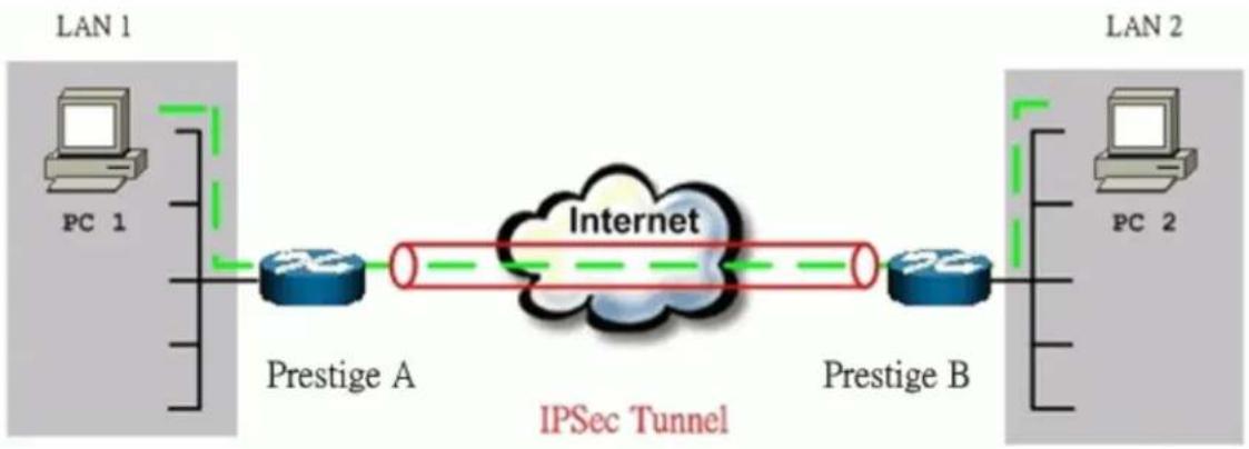
flowchart
graph LR
    subgraph LAN 1
        PC1["PC 1"]
        LAN1["LAN 1"]
        LAN2["LAN 2"]
    end

    subgraph LAN 2
        PC2["PC 2"]
        LAN2["LAN 2"]
    end

    LAN1 --> PrestigeA["Prestige A"]
    PrestigeA --> Internet["Internet"]
    Internet --> PrestigeB["Prestige B"]
    PrestigeA -.->|Green dashed arrow| Internet
    PrestigeB -.->|Red dashed arrow| Internet
    style LAN1 fill:#f9f,stroke:#333
    style LAN2 fill:#bbf,stroke:#333
The IP addresses we use in this example are as shown below.
| PC 1 | P-202H Plus v2 A | P-202H Plus v2 B | PC 2 |
| 202.132.155.33 | LAN: 202.132.155.1WAN: 202.132.154.1 | LAN: 140.130.10.1WAN: 168.10.10.66 | 140.130.10.33 |
Note: The following configurations are supposed both two VPN gateways have fixed IP addresses. If one of VPN gateways uses dynamic IP, we enter 0.0.0.0 as the secure gateway IP address. In this case, the VPN connection can only be initiated from dynamic side to fixed side to update its dynamic IP to the fixed side. However, if both gateways use dynamic IP addresses, it is no way to establish VPN connection at all.
1. Setup P-202H Plus v2 A
- Using a web browser, login P-202H Plus v2 by giving the LAN IP address of P-202H Plus v2 in URL field. Default LAN IP is 192.168.1.1, default password to login web configurator is 1234.
- Click Advanced, and click VPN tab on the left.
-
On the SUMMARY menu, Select a policy to edit by clicking Edit.
-
On the CONFIGURE-IKE menu, check Active check box and give a name to this policy.
- Select IPSec Keying Mode to IKE and Negotiation Mode to Main, as we configured in P-202H Plus v2 B.
- Source IP Address Start and Source IP Address End are PC 1 IP in this example. (the secure host behind P-202H Plus v2 A)
- Destination IP Address Start and Destination IP Address End are PC 2 IP in this example. (the secure remote host)
- My IP Addr is the WAN IP of P-202H Plus v2 A.
- Secure Gateway IP Addr is the remote secure gateway IP, that is P-202H Plus v2 B WAN IP in this example.
- Select Encapsulation Mode to Tunnel.
- Check the ESP check box. (AH can not be used in SUA/NAT case)
- Select Encryption Algorithm to DES and Authentication Algorithm to MD5, as we configured in P-202H Plus v2 B.
- Enter the key string 12345678 in the Preshared Key text box, and click Apply.
See the screen shot:

If you use SMT management, the VPN configurations are as shown below.
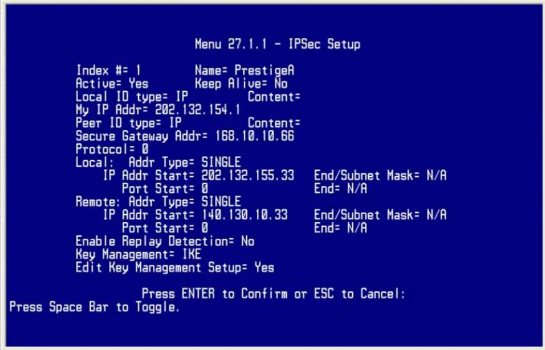
- Edit IKE settings by selecting 'Edit IKE Setup' option in menu27.1.1 to 'Yes' and then pressing 'Enter'.
- There are two phases for IKE:
In Phase 1, two IKE peers establish a secure channel for key exchanging. In Phase 2, two peers negotiate general purpose SAs which are secure channels for data transmission.
Note that any configuration in 'IKE Setup' should be consistent in both P-202H Plus v2 A and P-202H Plus v2 B.
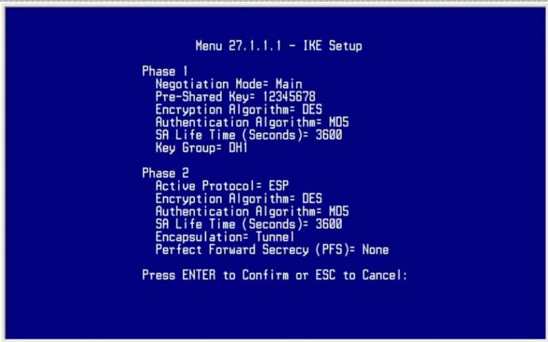
2. Setup P-202H Plus v2 B
Similar to the settings for P-202H Plus v2 A, P-202H Plus v2 B is configured in the same way.
- Using a web browser, login P-202H Plus v2 by giving the LAN IP address of P-202H Plus v2 in URL field.
- Click Advanced, and click VPN tab on the left.
- On the SUMMARY menu, Select a policy to edit by clicking Edit.
- On the CONFIGURE-IKE menu, check Active check box and give a name to this policy.
- Select IPSec Keying Mode to IKE and Negotiation Mode to Main, as we configured in P-202H Plus v2 A.
- Source IP Address Start and Source IP Address End are PC 2 IP in this example. (the secure host behind P-202H Plus v2 B)
- Destination IP Address Start and Destination IP Address End are PC 1 IP in this example. (the secure remote host) Note: You may assign a range of Local/Remote IP addresses for multiple VPN sessions.
- My IP Addr is the WAN IP of P-202H Plus v2 B.
- Secure Gateway IP Addr is the remote secure gateway IP, that is P-202H Plus v2 A WAN IP in this example.
- Select Encapsulation Mode to Tunnel.
-
Check the ESP check box. (AH can not be used in SUA/NAT case)
-
Select Encryption Algorithm to DES and Authentication Algorithm to MD5, as we configured in P-202H Plus v2 A.
- Enter the key string 12345678 in the Preshared Key text box, and click Apply.
See the screen shot:
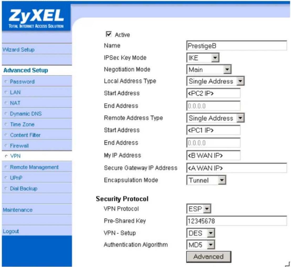
If you use SMT management, the VPN configurations are as shown below.
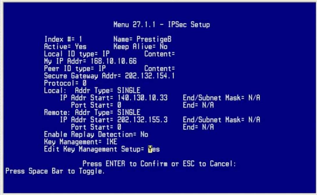
- Edit IKE settings by selecting 'Edit IKE Setup' option in menu27.1.1 to 'Yes' and then pressing 'Enter'.
- There are two phases for IKE:
In Phase 1, two IKE peers establish a secure channel for key exchanging. In Phase 2, two peers negotiate general purpose SAs which are secure channels for data transmission.
Note that any configuration in 'IKE Setup' should be consistent in both P-202H Plus v2 A and P-202H Plus v2 B.
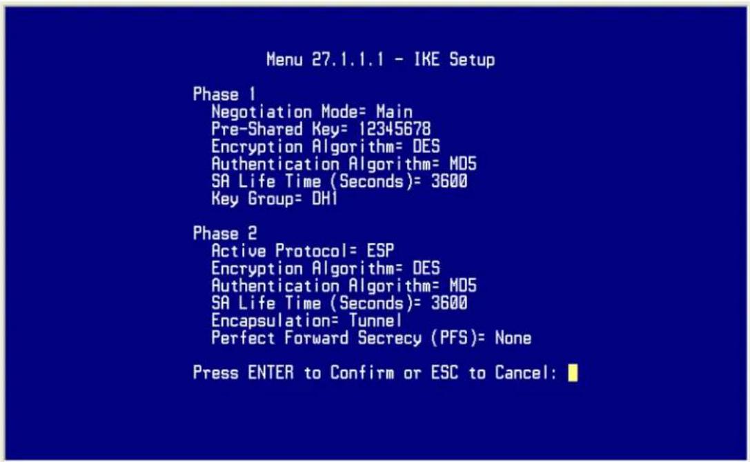
3. Troubleshooting
Q: How do we know the above tunnel works?
A: If the connection between PC 1 and PC 2 is ok, we know the tunnel works.
Please try to ping from PC 1 to PC 2 (or PC 2 to PC 1). If PC 1 and PC 2 can ping to each other, it means that the IPSec tunnel has been established successfully. If the ping fail, there are two methods to troubleshoot IPSec in P-202H Plus v2.
- Menu 27.2, SA Monitor
Through menu 27.2, you can monitor every IPSec connections running in P-202H Plus v2 presently. The second column of each entry indicates the IPSec rule name. So, if you can't see the name of your IPSec rule, it means that the SA establishment fails. Please go back Menu 27 to check your settings.
| Menu 27.2 - SA Monitor | ||||
| # | Name | Encap. IPSec ALgorithm | ||
| 1 | P-202H Plus v2A DES-SHA1 | ca24f1eb6616b7c4 | 732c211ae9b01a0f | Tunnel ESP |
Select Command= Refresh
Select Connection= N/A
Press ENTER to Confirm or ESC to Cancel:
• Using CI command 'ipsec debug 1'
Please enter 'ipsec debug 1' in Menu 24.8. There should be lots of detailed messages printed out to show how negotiations are taken place. If IPSec connection fails, please dump 'ipsec debug 1' for our analysis. The following shows an example of dumped messages.
P-202H Plus v2> ipsec debug 1
IPSEC debug level 1
P-202H Plus v2> catcher(): recv pkt numPkt<1>
get_hdr nxt_payload<1> exchMode<2> m_id<0> len<80>
f76af206 b187aae3 00000000 00000000 01100200 00000000 00000050
00000034
00000001 00000001 00000028 01010001 00000020 01010000 80010001
80020001
80040001 80030001 800b0001 800c0e10
In isadb_get_entry, nxt_pyld=1, exch=2
New SA
In responder
isadb_create_entry(): RESPONSOR:
##entering spGetPeerByAddr...
<deleted>
4. View Log
To view the log for IPSec and IKE connections, please enter menu 27.3, View IPSec Log. The log menu is also useful for troubleshooting please capture to us if necessary. Please refer to the example below.
Index: Date: Log:
001 01 Jan 00:15:11 <<<INFO Sending IKE Packet == 15
002 01 Jan 00:15:11 <<<Sending IKE Packet == 15
003 01 Jan 00:15:11 <<<INFO Sending IKE Packet == 15
004 01 Jan 00:15:11 <<<Sending IKE Packet == 15
005 01 Jan 00:15:16 <<<Sending IKE Packet == 0
006 01 Jan 00:15:16 >>>MM Receiving IKE Packet == 2
007 01 Jan 00:15:18 <<<Sending IKE Packet == 3
008 01 Jan 00:15:18 >>>MM Receiving IKE Packet == 4
009 01 Jan 00:15:19 <<<Sending IKE Packet == 5
010 01 Jan 00:15:19 >>>MM Receiving IKE Packet == 6
011 01 Jan 00:15:19 <<<Sending IKE Packet == 6
012 01 Jan 00:15:19 >>>QM Receiving IKE Packet == 15
013 01 Jan 00:15:19 <<<Sending IKE Packet == 15
Clear IPSec Log (y/n):
Note, the 'Log' column in the current 3.50(WA.0) firmware just shows the IKE state flow. In the future firmware, we will enhance it to show packet information (such as protocol type, port number).
- Secure Gateway to PC
Soft-PK VPN to P-202H Plus v2 Tunneling
- Setup Soft-PK VPN
- Setup P-202H Plus v2 VPN
This page guides us to setup a VPN connection between the VPN software and P-202H Plus v2 router. There will be several devices we need to setup for this case. They are VPN software and P-202H Plus v2 router.
As the figure shown below, the tunnel between PC 1 and P-202H Plus v2 ensures the packets flow between them are secure. Because the packets go through the IPSec tunnel are encrypted. To setup this VPN tunnel, the required settings for the software and P-202H Plus v2 are explained in the following sections.

flowchart
graph LR
    A["PC 1"] -->|A IPSec Tunnel| B["Internet"]
    B -->|B Prestige| C["PC 2"]
    style A fill:#f9f,stroke:#333
    style B fill:#ccf,stroke:#333
    style C fill:#cfc,stroke:#333
The IP addresses we use in this example are as shown below.
| PC 1 | P-202H Plus v2 | PC2 |
| 202.132.155.33 | LAN: 202.132.171.1WAN: 202.132.170.1 | 202.132.171.33 |
1. Setup Soft-PK VPN
- Open Soft-PK Security Policy Editor
- Add a new connection named 'P-202H Plus v2' as shown below.
- Select Connection Security to Secure
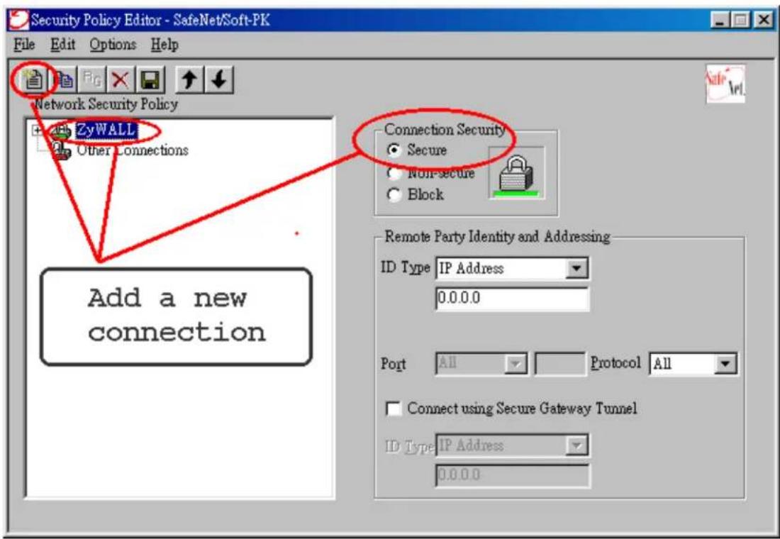
Remote Party Identity and Addressing settings:
- In ID Type option, please choose IP Address option, and enter the IP address of the remote PC (PC 2 in this case).
- Check Connect using Secure Gateway Tunnel, please also select IP
Address as ID Type, and enter P-202H Plus v2's WAN
IP address in the following field.
The detailed configuration is shown in the following figure.

Pre-Share Key Settings:
- Extend P-202H Plus v2 icon, you may see My Identity.
- Click My Identity, click the Pre-Shared Key icon in the right side of the window.
- Enter a key you that later you will also need to configure in P-202H Plus v2 in the pop out windows. In this example, we enter
- See below.
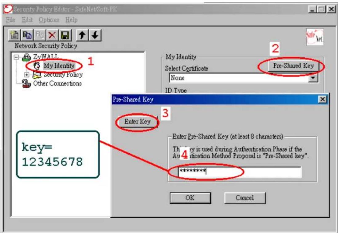
Security Policy Settings:
- Click Security Policy option to choose Main Mode as Phase 1 Negotiation Mode

- Extend Security Policy icon, you will see two icons, Authentication (Phase 1) and Key Exchange (Phase 2).
- The settings shown in the following two figures for both Phases are our examples. You can choose any, but they should match whatever you enter in P-202H Plus
v2.

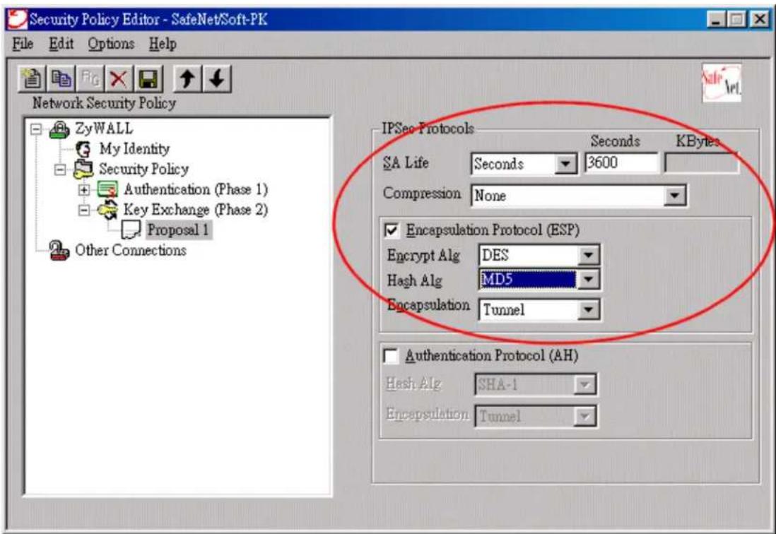
2. Setup P-202H Plus v2 VPN
- Using a web browser, login P-202H Plus v2 by giving the LAN IP address of P-202H Plus v2 in URL field. Default LAN IP is 192.168.1.1, default password to login web configurator is 1234.
- Click Advanced, and click VPN tab on the left.
- On the SUMMARY menu, Select a policy to edit by clicking Edit.
- On the CONFIGURE-IKE menu, check Active check box and give a name to this policy.
- Select IPSec Keying Mode to IKE and Negotiation Mode to Main, as we configured in Soft-PK.
- Source IP Address Start and Source IP Address End are PC 2 IP in this example. (the secure host behind P-202H Plus v2)
- Destination IP Address Start and Destination IP Address End are PC 1 in this example. (the secure remote host) Note: You may assign a range of Source/Destination IP addresses for multiple VPN sessions.
- My IP Addr is the WAN IP of P-202H Plus v2.
- Secure Gateway IP Addr is the remote secure gateway IP, that is PC 1 in this example.
- Select Encapsulation Mode to Tunnel.
- Check the ESP check box. (AH can not be used in SUA/NAT case)
- Select Encryption Algorithm to DES and Authentication Algorithm to SHA1, as we configured in Soft-PK.
- Enter the key string 12345678 in the Preshared Key text box, and click Apply.
Figure 8: See the VPN rule screen shot
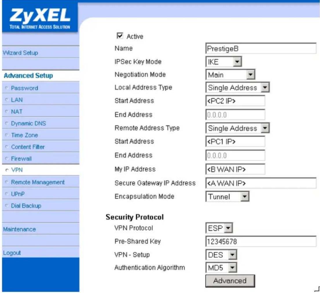
If you use SMT management, the VPN configurations are as shown below.
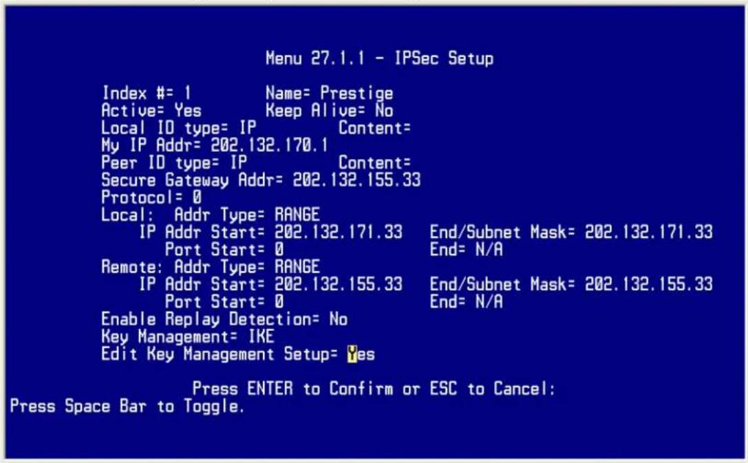
- Edit IKE settings by selecting 'Edit IKE Setup' option in menu27.1.1 to 'Yes' and then pressing 'Enter'.
- There are two phases for IKE:
In Phase 1, two IKE peers establish a secure channel for key exchanging.
In Phase 2, two peers negotiate general purpose SAs which are secure channels for data transmission.
Please note that any configuration in 'IKE Setup' should match the settings in VPN software.
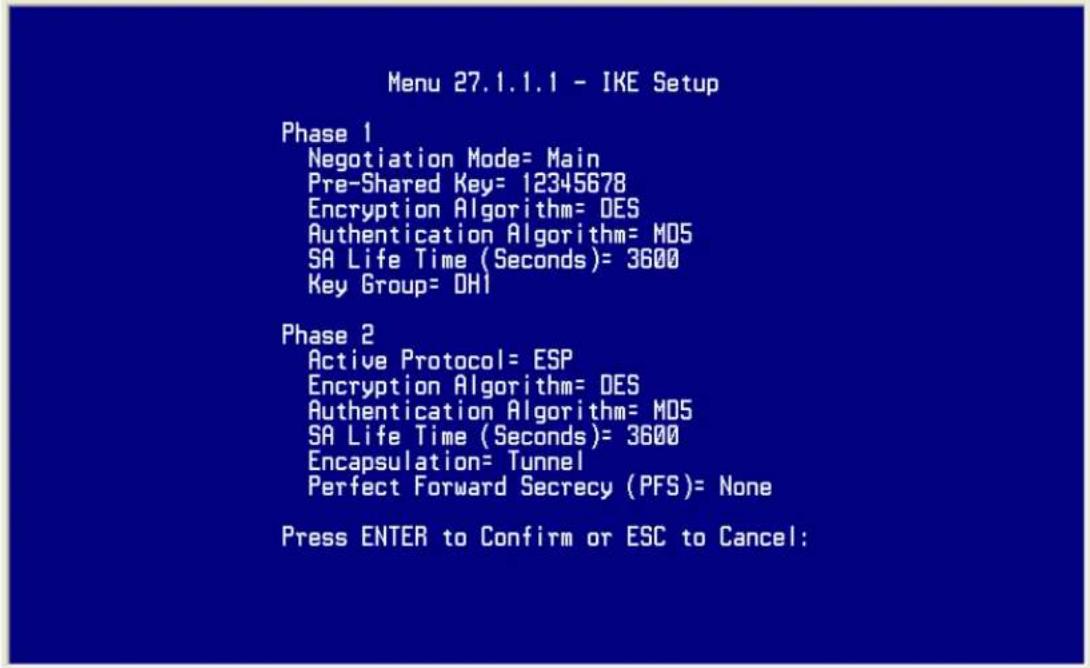
Network Diagram Key
In our network diagram figures, a dotted line indicates a logical connection (i.e., the two devices are not physically attached), a solid line indicates a physical connection (i.e., there is a physical link between the two devices and they are directly attached), and a pipe indicates a secure connection between two devices.
2. P-202H Plus v2 vs 3rd Party VPN Gateway
P-202H Plus v2 to P-202H Plus v2 Tunneling.
This page guides us to setup a VPN connection between two P-202H Plus v2 routers. Please note that, in addition to P-202H Plus v2 to P-202H Plus v2, P-202H Plus v2 can also talk to other VPN hardwards. The tested VPN hardware are shown below.
• Cisco 1720 Router, IOS 12.2(2)XH, IP/ADSL/FW/IDS PLUS IPSEC 3DES
- NetScreen 5, ScreenOS 2.6.0r6
- SonicWALL SOHO 2
- WatchGuard Firebox II
- ZyXEL VPN solution
- Avaya VPN
- Netopia VPN
- III VPN
As the figure shown below, the tunnel between P-202H Plus v2 1 and P-202H Plus v2 2 ensures the packets flow between PC 1 and PC 2 are secure. Because the packets go through the IPSec tunnel are encrypted. To achieve this VPN tunnel, the settings required for each P-202H Plus v2 are explained in the following sections.
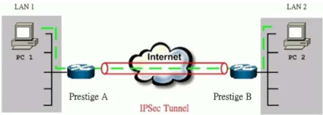
flowchart
graph LR
    subgraph_LAN_1["LAN 1"]
        PC1["PC 1"] --> PrestigeA["Prestige A"]
        PrestigeA --> Internet["Internet"]
        Internet --> PrestigeB["Prestige B"]
    end
    subgraph_LAN_2["LAN 2"]
        PC2["PC 2"] --> Internet
        PrestigeB --> Internet
    end
    style LAN_1 fill:#f9f,stroke:#333
    style LAN_2 fill:#bbf,stroke:#333
    note right of Internet
        IPSec Tunnel
    end
The IP addresses we use in this example are as shown below.
| PC 1 | P-202H Plus v2 A | P-202H Plus v2 B | PC 2 |
| 192.168.1.33 | LAN: 192.168.1.1WAN: 202.132.154.1 | LAN: 192.168.2.1WAN: 168.10.10.66 | 192.168.2.33 |
Note: The following configurations are supposed both two VPN gateways have fixed IP addresses. If one of VPN gateways uses dynamic IP, we enter 0.0.0.0 as the secure gateway IP address. In this case, the VPN connection can only be initiated from dynamic side to fixed side to update its dynamic IP to the fixed side. However, if both gateways use dynamic IP addresses, it is no way to establish VPN connection at all.
1. Setup P-202H Plus v2 A
-
Using a web browser, login P-202H Plus v2 by giving the LAN IP address of P-202H Plus v2 in URL field. Default LAN IP is 192.168.1.1, default password to login web configurator is 1234.
-
Click Advanced, and click VPN tab on the left.
- On the SUMMARY menu, Select a policy to edit by clicking Edit.
- On the CONFIGURE-IKE menu, check Active check box and give a name to this policy.
- Select IPSec Keying Mode to IKE and Negotiation Mode to Main, as we configured in P-202H Plus v2 B.
- Source IP Address Start and Source IP Address End are PC 1 IP in this example. (the secure host behind P-202H Plus v2 A)
- Destination IP Address Start and Destination IP Address End are PC 2 IP in this example. (the secure remote host)
- My IP Addr is the WAN IP of P-202H Plus v2 A.
- Secure Gateway IP Addr is the remote secure gateway IP, that is P-202H Plus v2 B WAN IP in this example.
- Select Encapsulation Mode to Tunnel.
- Check the ESP check box. (AH can not be used in SUA/NAT case)
- Select Encryption Algorithm to DES and Authentication Algorithm to MD5, as we configured in P-202H Plus v2 B.
- Enter the key string 12345678 in the Preshared Key text box, and click Apply.
See the screen shot:

If you use SMT management, the VPN configurations are as shown below.
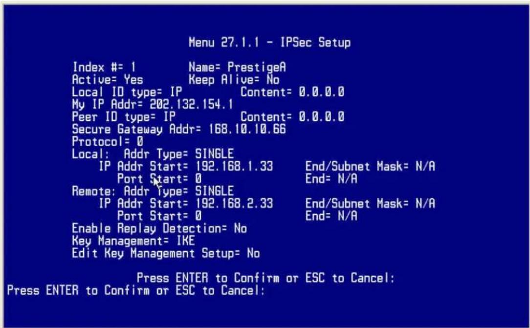
- Edit IKE settings by selecting 'Edit IKE Setup' option in menu27.1.1 to 'Yes' and then pressing 'Enter'.
- There are two phases for IKE:
In Phase 1, two IKE peers establish a secure channel for key exchanging. In Phase 2, two peers negotiate general purpose SAs which are secure channels for data transmission.
Note that any configuration in 'IKE Setup' should be consistent in both P-202H Plus v2 A and P-202H Plus v2 B.

2. Setup P-202H Plus v2 B
Similar to the settings for P-202H Plus v2 A, P-202H Plus v2 B is configured in the same way.
- Using a web browser, login P-202H Plus v2 by giving the LAN IP address of P-202H Plus v2 in URL field.
- Click Advanced, and click VPN tab on the left.
- On the SUMMARY menu, Select a policy to edit by clicking Edit.
- On the CONFIGURE-IKE menu, check Active check box and give a name to this policy.
- Select IPSec Keying Mode to IKE and Negotiation Mode to Main, as we configured in P-202H Plus v2 A.
- Source IP Address Start and Source IP Address End are PC 2 IP in this example. (the secure host behind P-202H Plus v2 B)
- Destination IP Address Start and Destination IP Address End are PC 1 IP in this example. (the secure remote host) Note: You may assign a range of Local/Remote IP addresses for multiple VPN sessions.
- My IP Addr is the WAN IP of P-202H Plus v2 B.
- Secure Gateway IP Addr is the remote secure gateway IP, that is P-202H Plus v2 A WAN IP in this example.
- Select Encapsulation Mode to Tunnel.
-
Check the ESP check box. (AH can not be used in SUA/NAT case)
-
Select Encryption Algorithm to DES and Authentication Algorithm to MD5, as we configured in P-202H Plus v2 A.
- Enter the key string 12345678 in the Preshared Key text box, and click Apply.
See the screen shot:

If you use SMT management, the VPN configurations are as shown below.
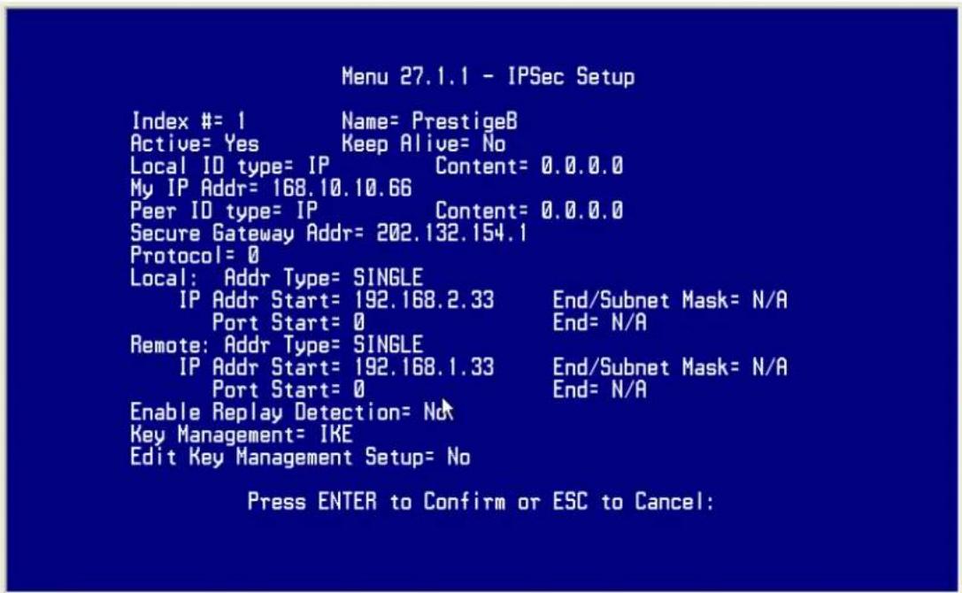
- Edit IKE settings by selecting 'Edit IKE Setup' option in menu 27.1.1 to 'Yes' and then pressing 'Enter'.
- There are two phases for IKE:
In Phase 1, two IKE peers establish a secure channel for key exchanging. In Phase 2, two peers negotiate general purpose SAs which are secure channels for data transmission.
Note that any configuration in 'IKE Setup' should be consistent in both P-202H Plus v2 A and P-202H Plus v2 B.
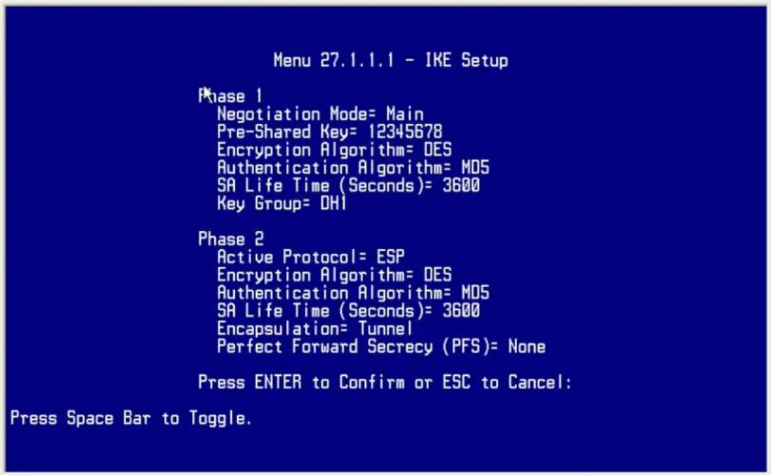
3. Troubleshooting
Q: How do we know the above tunnel works?
A: If the connection between PC 1 and PC 2 is ok, we know the tunnel works.
Please try to ping from PC 1 to PC 2 (or PC 2 to PC 1). If PC 1 and PC 2 can ping to each other, it means that the IPSec tunnel has been established successfully. If the ping fail, there are two methods to troubleshoot IPSec in P-202H Plus v2.
- Menu 27.2, SA Monitor
Through menu 27.2, you can monitor every IPSec connections running in P-202H Plus v2 presently. The second column of each entry indicates the IPSec rule name. So, if you can't see the name of your IPSec rule, it means that the SA establishment fails. Please go back Menu 27 to check your settings.
| Menu 27.2 - SA Monitor | ||||
| # | Name | Encap. IPSec ALgorithm | ||
| 1 | P-202H Plus v2A | ca24f1eb6616b7c4 | 732c211ae9b01a0f | Tunnel ESP |
DES-SHA1
2
3
4
5
6
7
8
9
10
Select Command= Refresh
Select Connection= N/A
Press ENTER to Confirm or ESC to Cancel:
• Using CI command 'ipsec debug 1'
Please enter 'ipsec debug 1' in Menu 24.8. There should be lots of detailed messages printed out to show how negotiations are taken place. If IPSec connection fails, please dump 'ipsec debug 1' for our analysis. The following shows an example of dumped messages.
P-202H Plus v2> ipsec debug 1
IPSEC debug level 1
P-202H Plus v2> catcher(): recv pkt numPkt<1>
get_hdr nxt_payload<1> exchMode<2> m_id<0> len<80>
f76af206 b187aae3 00000000 00000000 01100200 00000000 00000050 00000034
00000001 00000001 00000028 01010001 00000020 01010000 80010001 80020001
80040001 80030001 800b0001 800c0e10
In isadb_get_entry, nxt_pyld=1, exch=2
New SA
In responder
isadb_create_entry(): RESPONSOR:
##entering spGetPeerByAddr...
<deleted>
4. View Log
To view the log for IPSec and IKE connections, please enter menu 27.3, View IPSec Log. The log menu is also useful for troubleshooting please capture to us if necessary. The example shown below is a successful IPSec connection.
| Index: Date/Time: Log: | ||
| 001 | 01 Jan 10:23:22 | !! Cannot find outbound SA for rule <1> |
| 002 | 01 Jan 10:23:22 | Send Main Mode request to <168.10.10.66> |
| 003 | 01 Jan 10:23:22 | Send:<SA> |
| 004 | 01 Jan 10:23:22 | Recv:<SA> |
| 005 | 01 Jan 10:23:24 | Send:<KE><NONCE> |
| 006 | 01 Jan 10:23:24 | Recv:<KE><NONCE> |
| 007 | 01 Jan 10:23:26 | Send:<ID><HASH> |
| 008 | 01 Jan 10:23:26 | Recv:<ID><HASH> |
| 009 | 01 Jan 10:23:26 | Phase 1 IKE SA process done |
| 010 | 01 Jan 10:23:26 | Start Phase 2: Quick Mode |
| 011 | 01 Jan 10:23:26 | Send:<HASH><SA><NONCE><ID><ID> |
| 012 | 01 Jan 10:23:26 | Recv:<HASH><SA><NONCE><ID><ID> |
| 013 | 01 Jan 10:23:26 | Send:<HASH> |
| Clear IPSec Log (y/n): | ||
P-202H Plus v2 to Cisco Tunneling
This page guides us to setup a VPN connection between P-202H Plus v2 and Cisco router. As the figure shown below, the tunnel between P-202H Plus v2 and Cisco Router ensures the packets flow between them are secure. To setup this VPN tunnel, the required settings for P-202H Plus v2 and Cisco Router are explained in the following sections.
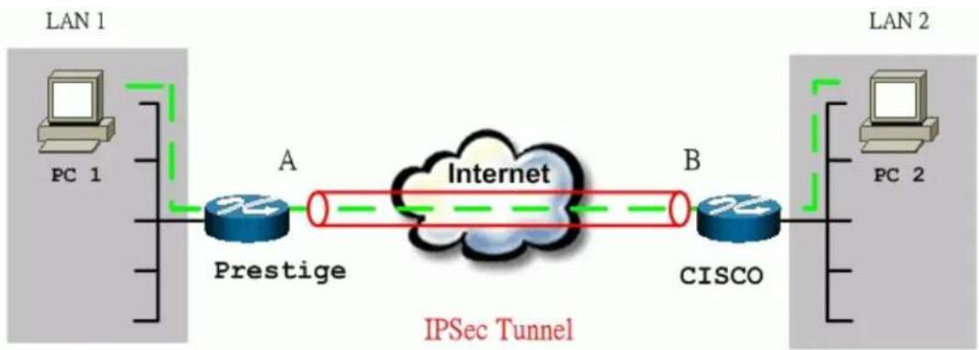
flowchart
graph LR
    subgraph LAN 1
        PC1["PC 1"] --> Prestige["Prestige"]
        Prestige -->|A| Internet["Internet"]
        Internet -->|B| Cisco["CISCO"]
    end
    subgraph LAN 2
        PC2["PC 2"] --> Cisco
        Cloud["IPSec Tunnel"] -->|Green dashed arrow| Prestige
        Cloud -->|Green dashed arrow| Cisco
    end
The IP addresses we use in this example are as shown below.
| PC 1 | P-202H Plus v2 | Cisco | PC 2 |
| 192.168.1.33 | LAN: 192.168.1.1WAN: 172.21.10.50 | LAN: 192.168.2.1WAN: 140.113.10.50 | 192.168.2.2 |
Note:
- When using Cisco Router to establish VPN, back-to-back connection is not applicable. In other words, the WAN IP of P-202H Plus v2 and Cisco router can't be in the same subnet.
- The following configurations are supposed both two VPN gateways have fixed IP addresses. If one of VPN gateways uses dynamic IP, we enter 0.0.0.0 as the secure gateway IP address. In this case, the VPN connection can only be initiated from dynamic side to fixed side to update its dynamic IP to the fixed side. From this connection, the source IP is obtained and then update to the previous 0.0.0.0 field. However, if both gateways use dynamic IP addresses, it is no way to establish VPN connection at all.
If the WAN IP of P-202H Plus v2 is also dynamic IP, we enter 0.0.0.0 as its My IP Address. When this IP is given by ISP, it will update to this field.
1. Setup P-202H Plus v2
- Login P-202H Plus v2 by giving the LAN IP address of P-202H Plus v2 in URL field. Default LAN IP is 192.168.1.1, default password to login web configurator is 1234.
- Click Advanced, and click VPN tab on the left.
- On the SUMMARY menu, Select a policy to edit by clicking Edit.
- On the CONFIGURE-IKE menu, check Active check box and give a name to this policy.
- Select IPSec Keying Mode to IKE and Negotiation Mode to Main, as we configured in Sonicwall.
- Source IP Address Start and Source IP Address End are PC 1 IP in this example. (the secure host behind P-202H Plus v2)
- Destination IP Address Start and Destination IP Address End are PC 2 IP in this example. (the secure remote host)
- My IP Addr is the WAN IP of P-202H Plus v2.
- Secure Gateway IP Addr is the remote secure gateway IP, that is Sonicwall WAN IP in this example.
- Select Encapsulation Mode to Tunnel.
-
Check the ESP check box. (AH can not be used in SUA/NAT case)
-
Select Encryption Algorithm to DES and Authentication Algorithm to MD5, as we configured in Sonicwall.
- Enter the key string 12345678 in the Preshared Key text box, and click Apply.
See the screen shot:

2 Setup Cisco
There are two ways to configure Cisco VPN, use commands from console or use Cisco ConfigMaker. Cisco ConfigMaker is an easy-to-use Windows 98/Me/NT/2000 application that configures Cisco routers, switches, hubs, and other devices. We will guide you how to setup IPSec by using Cisco ConfigMaker
in section 2.1. If you prefer to use commands from console, please go to section 2.2.
2.1 Setup Ciscro by ConfigMaker
You can download Cisco ConfigMaker from http://www.cisco.com/warp/public/cc/pd/nemnsw/cm/index.shtml.
- Select AutoDetect device Wizard in Devices window.
- Make sure that the console has been connected to your PC. If the router is detected successfully, a Cisco router should appear in the Network Diagram Window.
- Click right button of the mouse, choose Device Properties.... In Passwords tab, setup the passwords for this router.
See the screen shot:
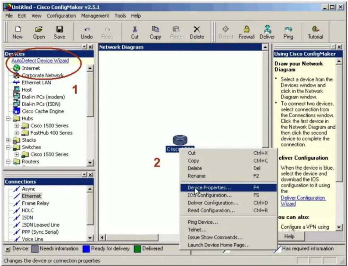
- From Devices window choose a router, and add this router in Network Diagram. Rename it as "P-202H Plus v2". Assign passwords, choose TCP/IP as it's protocol, and then set the interface of WAN slot 0 as 1 Ethernet.
See the screen shot:
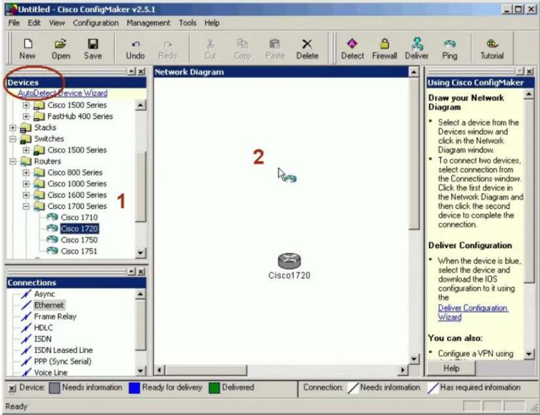
- Layout your network topology in the Network Diagram as shown below. You may choose network components, such as hosts, Internet, Ethernet LAN from the Devices window.
See the screen shot:
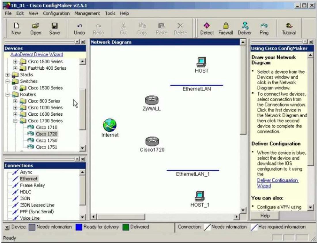
- Connect the network components by Ethernet from the Connections window in the left bottom. Specify the WAN and LAN IP addresses to P-202H Plus v2 and Cisco.
See the screen shot:
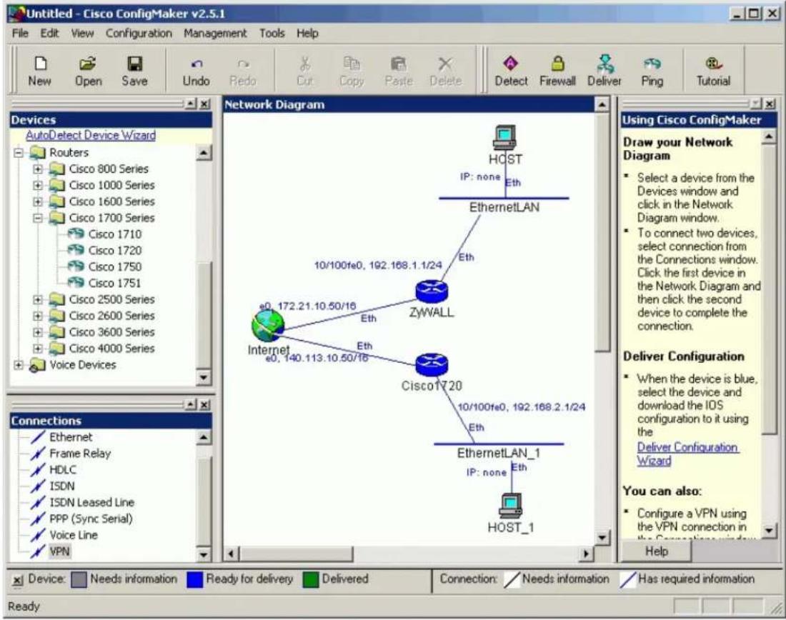
- Select VPN from Connections window. During this stage, you have to enter the pre-shared key, "12345678".
See the screen shot:
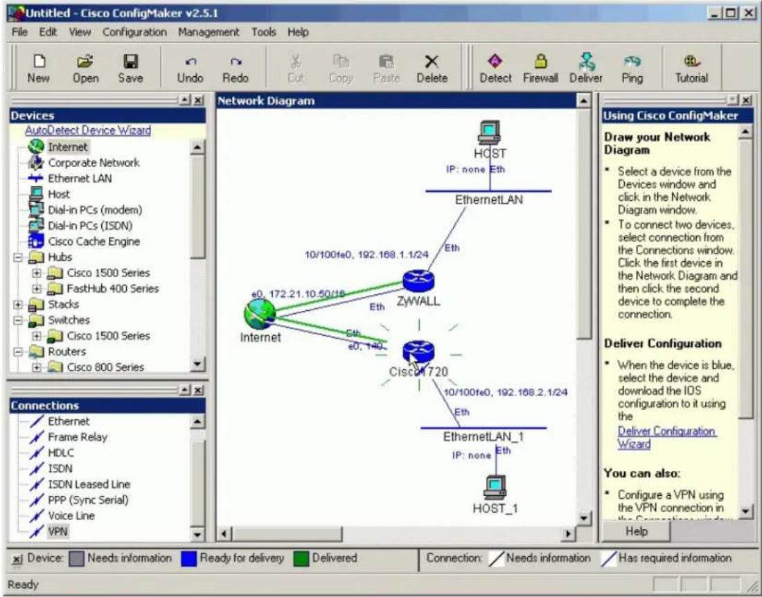
- Select VPN, then click the right button of the mouse, and choose connection Properties.... Setup IPSec parameters as shown below. Note that the parameters you set here should match settings in P-202H Plus v2. In IKE Advanced Settings, Encryption Algorithm is 56-bit DES, Authentication Algorithm is MD5 and the SA lifetime is 1 hr. In IPSec Transform, Encryption Algorithm is 56-bit DES, Authentication Algorithm is MD5, and SA lifetime is 1 hr.
See the screen shot:
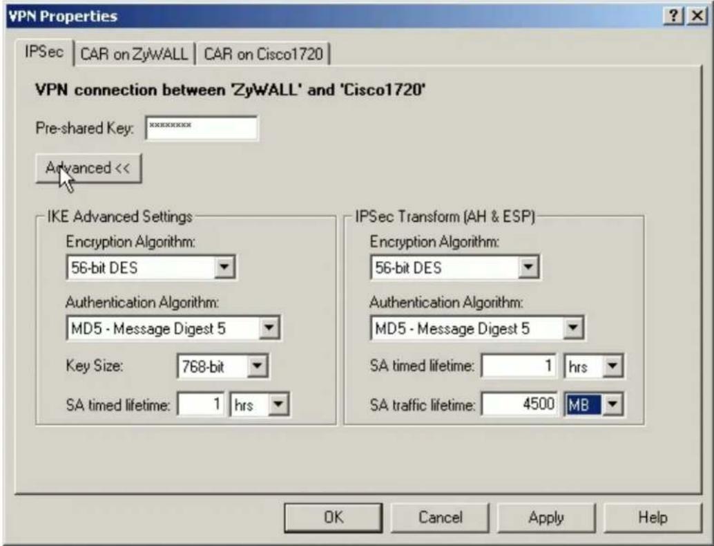
- Choose the Cisco router, and click Deliver to save the settings.
See the screen shot:
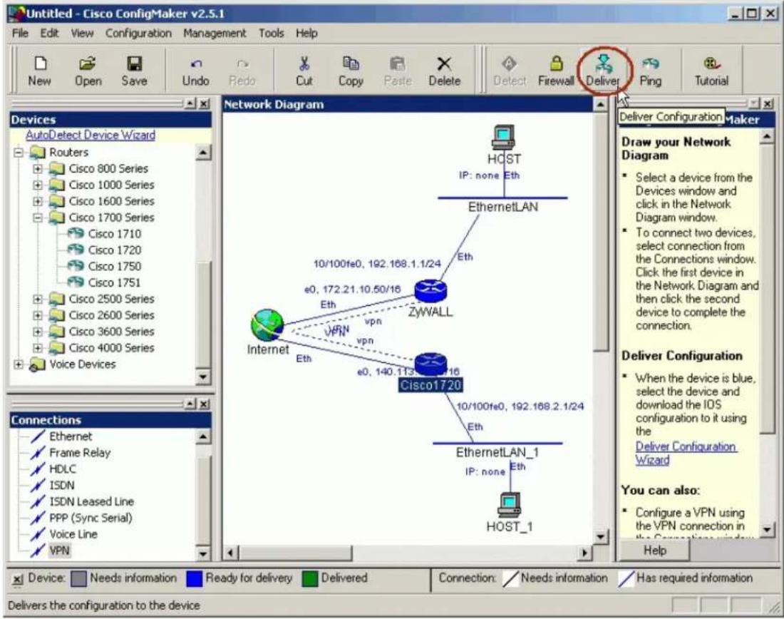
-
Enter Cisco commands mode from console and check if Cisco can make a successful ping to P-202H Plus v2. You might have to tune the configuration to accommodate your practical environment. For more detailed information, please go to http://www.cisco.com
-
In config mode, enter a command "crypto ipsec transform-set cm-transformset-1 esp-des esp-md5-hmac".
-
After all of the settings, if PC1 and PC2 can reach each other, then IPSec VPN has been established successfully. There is also an useful command to debug IPSec VPN, "debug crypto ipsec".
2.2 Setup Cisco by Commands
Note that, in order to setup Cisco by commands, you have to connect your PC and Cisco route by a console cable. Enter the following commands one per line.
Cisco1720#config
Cisco1720#
!
version 12.2
no parser cache
no service single-slot-reload-enable
service timestamps debug uptime
service timestamps log uptime
service password-encryption
!
hostname Cisco1720
!
logging rate-limit console 10 except errors
enable password 7 1543595F50
!
memory-size iomem 15
mmi polling-interval 60
no mmi auto-configure
no mmi pvc
mmi snmp-timeout 180
ip subnet-zero
!
!
no ip domain-lookup
!
ip dhcp pool 1
network 192.168.2.0 255.255.255.0
default-router 192.168.2.1
!
ip audit notify log
ip audit po max-events 100
ip ssh time-out 120
ip ssh authentication-retries 3
no ip dhcp-client network-discovery
!
crypto isakmp policy 1
hash md5
authentication pre-share
lifetime 3600
crypto isakmp key 12345678 address 172.21.10.50
!
crypto ipsec transform-set cm-transformset-1 esp-des esp-md5-hmac
crypto mib ipsec flowmib history tunnel size 200
crypto mib ipsec flowmib history failure size 200
!
crypto map cm-cryptomap local-address Ethernet0
crypto map cm-cryptomap 1 ipsec-isakmp
set peer 172.21.10.50
set transform-set cm-transformset-1
match address 100

interface Ethernet0
description connected to Internet
ip address 140.113.10.50 255.255.0.0
half-duplex

crypto map cm-cryptomap

interface FastEthernet0
description connected to EthernetLAN_1
ip address 192.168.2.1 255.255.255.0
speed auto

router rip
version 1
passive-interface Ethernet0
network 140.113.0.0
network 192.168.2.0
no auto-summary

ip classless
ip route 0.0.0.0 0.0.0.0 Ethernet0
no ip http server

access-list 100 permit ip 192.168.2.0 0.0.0.255 192.168.1.0 0.0.0.255

snmp-server community public RO

line con 0
exec-timeout 0 0
password 7 06575D7218
login

line aux 0
line vty 0 4
password 7 11584B5643
login

line vty 5 15
login
no scheduler allocate end
After all of the settings, if PC1 and PC2 can reach each other, then IPSec VPN has been established successfully. There is also a useful command to debug IPSec VPN, "debug crypto ipsec".
P-202H Plus v2 to SonicWALL Tunneling
This page guides us to setup a VPN connection between P-202H Plus v2 and SonicWALL. As the figure shown below, the tunnel between PC 1 and PC 2 ensures the packets flow between them are secure. To setup this VPN tunnel, the required settings for P-202H Plus v2 and SonicWALL are explained in the following sections.
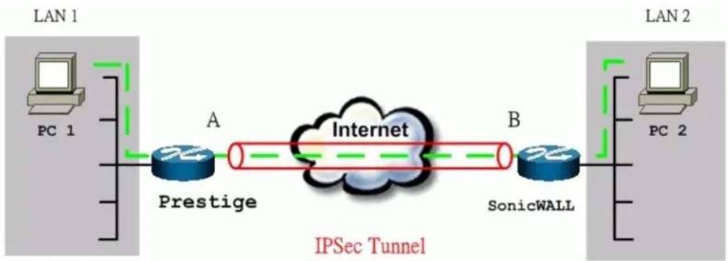
flowchart
graph LR
    subgraph LAN 1
        PC1["PC 1"] --> Prestige["Prestige"]
        Prestige --> A["A"]
        A --> Internet["Internet"]
        Internet --> B["B"]
        B --> SonicWALL["SonicWALL"]
    end
    subgraph LAN 2
        PC2["PC 2"] --> SonicWALL
        SonicWALL --> B
        style LAN 1 fill:#f9f,stroke:#333
        style LAN 2 fill:#bbf,stroke:#333
    end
    note right of LAN 1: IPSec Tunnel
The IP addresses we use in this example are as shown below.
| PC 1 | P-202H Plus v2 | Sonicwall | PC 2 |
| 192.168.1.33 | LAN: 192.168.1.1WAN: 202.132.154.1 | LAN: 192.168.181.1WAN: 168.10.10.66 | 192.168.181.10 |
Note: The following configurations are supposed both two VPN gateways have fixed IP addresses. If one of VPN gateways uses dynamic IP, we enter 0.0.0.0 as the secure gateway IP address. In this case, the VPN connection can only be initiated from dynamic side to fixed side to update its dynamic IP to the fixed side. From this connection, the source IP is obtained and then update to the previous 0.0.0.0 field. However, if both gateways use dynamic IP addresses, it is no way to establish VPN connection at all.
1. Setup P-202H Plus v2
- Login P-202H Plus v2 by giving the LAN IP address of P-202H Plus v2 in URL field. Default LAN IP is 192.168.1.1, default password to login web configurator is 1234.
- Click Advanced, and click VPN tab on the left.
- On the SUMMARY menu, Select a policy to edit by clicking Edit.
- On the CONFIGURE-IKE menu, check Active check box and give a name to this policy.
- Select IPSec Keying Mode to IKE and Negotiation Mode to Main, as we configured in Sonicwall.
- Source IP Address Start and Source IP Address End are PC 1 IP in this example. (the secure host behind P-202H Plus v2)
- Destination IP Address Start and Destination IP Address End are PC 2 IP in this example. (the secure remote host)
- My IP Addr is the WAN IP of P-202H Plus v2.
- Secure Gateway IP Addr is the remote secure gateway IP, that is Sonicwall WAN IP in this example.
- Select Encapsulation Mode to Tunnel.
- Check the ESP check box. (AH can not be used in SUA/NAT case)
- Select Encryption Algorithm to DES and Authentication Algorithm to MD5, as we configured in Sonicwall.
- Enter the key string 12345678 in the Preshared Key text box, and click Apply.
See the screen shot:
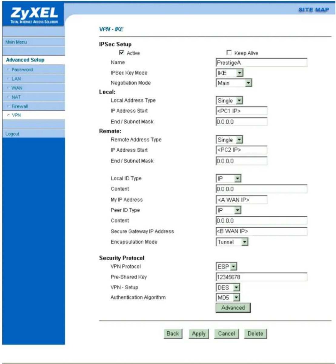
2. Setup SonicWALL
- Login SonicWALL by giving the LAN IP address of SonicWALL, default is 192.168.168.1.
- Click Gernal menu, and click Network tab.
- Select NAT Enabled as the Network Addressing Mode.
- In LAN Settings, enter a LAN IP and Subnet Mask for SonicWALL.
-
In WAN Settings, enter a WAN IP, Subnet Mask, and WAN Gateway for SonicWALL.
-
In DNS Settings, enter the DNS IP.
-
Click Update to save the settings to SonicWALL.
-
Click DHCP, enable DHCP, and the Dynamic Ranges.
-
Click VPN, click Configure tab.
-
In Security Association option, select Add New SA.
-
In IPSec Keying Mode option, select IKE using pre-shared secret.
-
In Name option, give a name for this SA.
-
In IPSec Gateway Address, enter P-202H Plus v2 WAN IP
-
In Encryption Method option, select Encrypt and Authenticate (ESP DES HMAC MD5).
-
In Shared Secret option, enter 12345678 as the secret key.
-
Click Add New Network.
-
In Edit VPN Destination Network, enter remote secure host in Network field, PC 1 in the case. And also enter its subnet mask and click Update.
-
Click Update to save VPN settings in VPN menu.
See the screen shot:
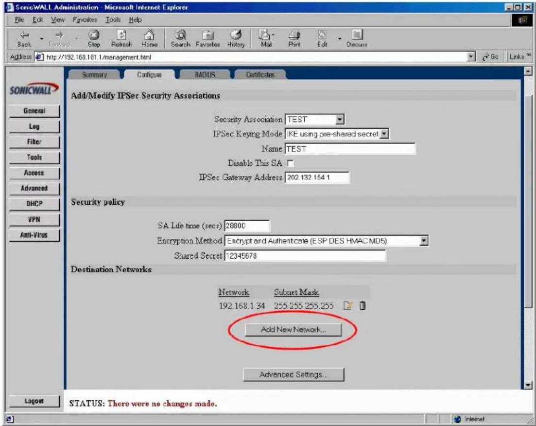
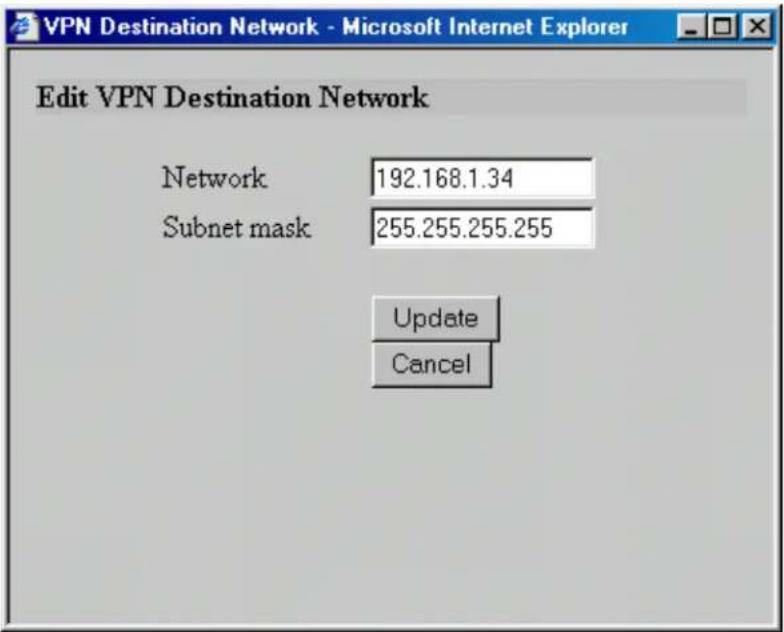
If the SA is up, you can see a new button, Renegotiate appears in the Summary screen.
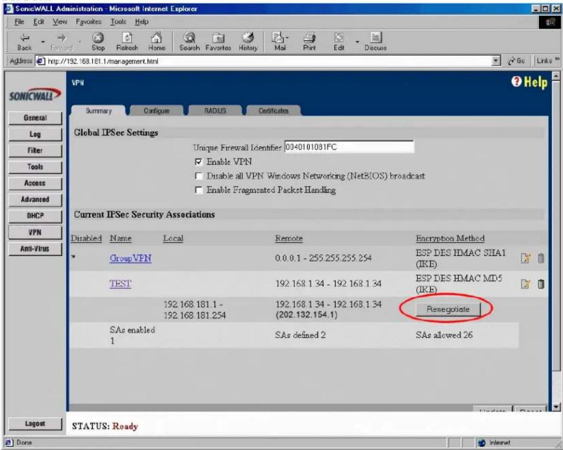
P-202H Plus v2 to WatchGuard Tunneling
This page guides us to setup a VPN connection between P-202H Plus v2 and WatchGuard. As the figure shown below, the tunnel between PC 1 and PC 2 ensures the packets flow between them are secure. To setup this VPN tunnel, the required settings for P-202H Plus v2 and WatchGuard are explained in the following sections.
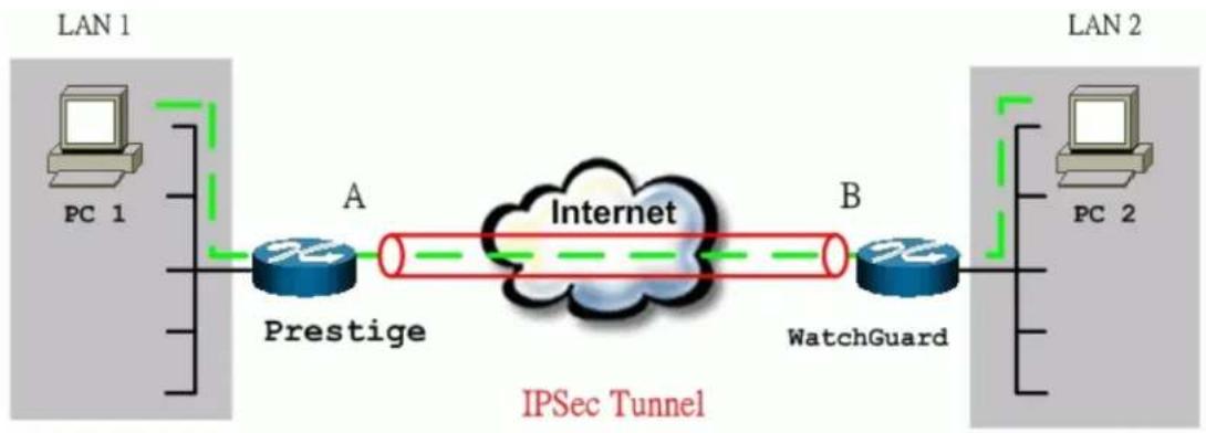
flowchart
graph LR
    subgraph LAN 1
        PC1["PC 1"] --> Prestige["Prestige"]
        Prestige -->|A| Internet["Internet"]
        Internet -->|B| WatchGuard["WatchGuard"]
    end
    subgraph LAN 2
        PC2["PC 2"] --> WatchGuard
        WatchGuard -->|B| Internet
        WatchGuard -->|C| IPSec["Tunnel"]
    end
The IP addresses we use in this example are as shown below.
| PC 1 | P-202H Plus v2 | WatchGuard | PC 2 |
| 192.168.1.33 | LAN: 192.168.1.1WAN: 202.132.154.1 | LAN: 192.168.2.1WAN: 168.10.10.66 | 192.168.2.33 |
Note: The following configurations are supposed both two VPN gateways have fixed IP addresses. If one of VPN gateways uses dynamic IP, we enter 0.0.0.0 as the secure gateway IP address. In this case, the VPN connection can only be initiated from dynamic side to fixed side to update its dynamic IP to the fixed side. From this connection, the source IP is obtained and then update to the previous 0.0.0.0 field. However, if both gateways use dynamic IP addresses, it is no way to establish VPN connection at all.
1. Setup P-202H Plus v2
- Login P-202H Plus v2 by giving the LAN IP address of P-202H Plus v2 in URL field. Default LAN IP is 192.168.1.1, default password to login web configurator is 1234.
- Click Advanced, and click VPN tab on the left.
- On the SUMMARY menu, Select a policy to edit by clicking Edit.
-
On the CONFIGURE-IKE menu, check Active check box and give a name to this policy.
-
Select IPSec Keying Mode to IKE and Negotiation Mode to Main.
- Source IP Address Start and Source IP Address End are PC 1 IP in this example. (the secure host behind P-202H Plus v2)
- Destination IP Address Start and Destination IP Address End are PC 2 IP in this example. (the secure remote host)
- My IP Addr is the WAN IP of P-202H Plus v2.
- Secure Gateway IP Addr is the remote secure gateway IP, that is WatchGuard WAN IP in this example.
- Select Encapsulation Mode to Tunnel.
- Check the ESP check box. (AH can not be used in SUA/NAT case)
- Select Encryption Algorithm to DES and Authentication Algorithm to MD5, as we configured in WatchGuard.
- Enter the key string 12345678 in the Preshared Key text box, and click Apply.
See the screen shot:
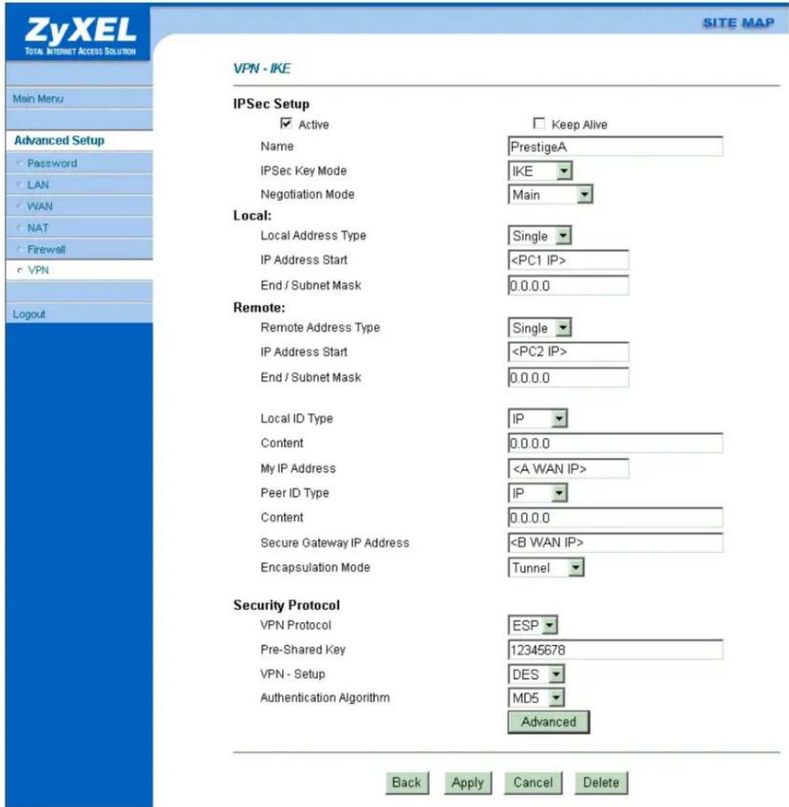
2. Setup WatchGuard
- In the QuickSetup Wizard, select Configure in Routed Mode, click Next.
- Enter IP of PC2, click OK.
- In External Interface, enter the WAN IP for WatchGuard; and in Trusted Interface, enter the LAN IP for WatchGuard. Then click Next.
- Enter the Default Gateway of WatchGuard then click Next twice.
-
Enter your passwords for Status and Configuration then click Next.
-
Select Use Serial Cable to Assign IP Address and Serial Port of your computer then click Next and OK.
- Turn the Firebox off and on again. Wait for the configuration file to be uploaded.
- In the 'WatchGuard Control Center' click on the Policy Manager icon.
- Pull down Network -> Branch Office VPN -> IPSec. See the figure below.
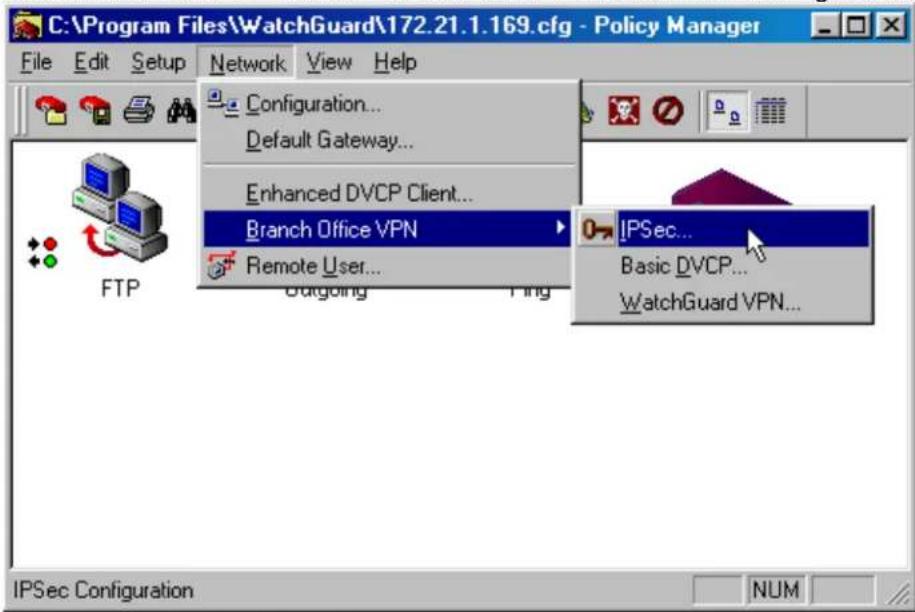
- Click Gateway, and click Add.
-
Enter a name for remote security gateway in Name field, enter the remote gateway IP in Remote Gateway IP field.
-
Select isakmp (dynamic) (IKE in P-202H Plus v2) as Key Negotiation Type and enter a string as Share Key.1
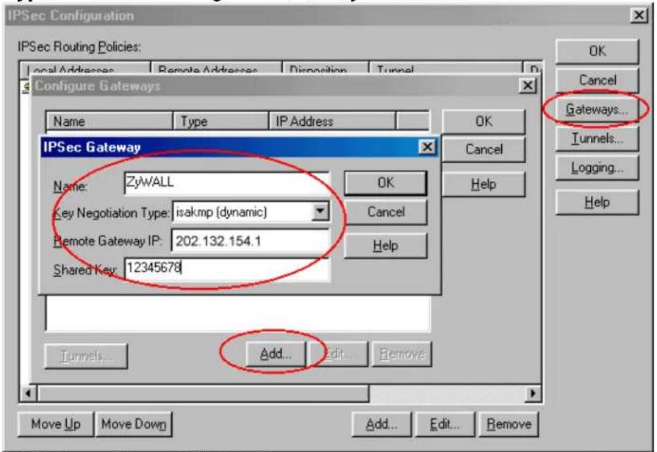
- Click Tunnels, and click Add.
- Select the Gateway you had created and click OK.
- Enter a name in Name field for this Tunnel.
-
Click Dynamic Security tab, select Type, Authentication and Encryption for your SAP. These settings must be consistent with P-202H Plus v2 settings.
-
Enable the Key expiration. Then click OK twice. (ESP, MD5-HMAC, DES-CBC)
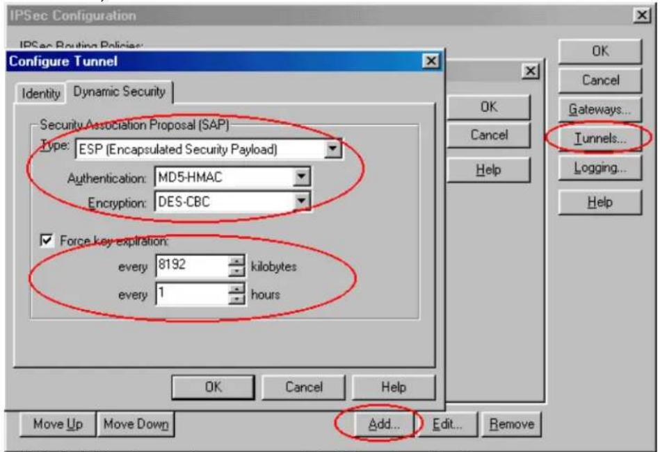
- Click Add in the main menu to Add Routing Policy.
- In Local Host, enter PC1 IP; in Remote Host, enter PC2 IP, then select Secure in Disposition and Tunnel you had created. Then click OK twice.
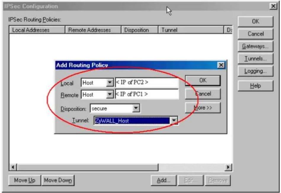
- Select 'Save to Firebox' and enter the write pass phrase for your WatchGuard.
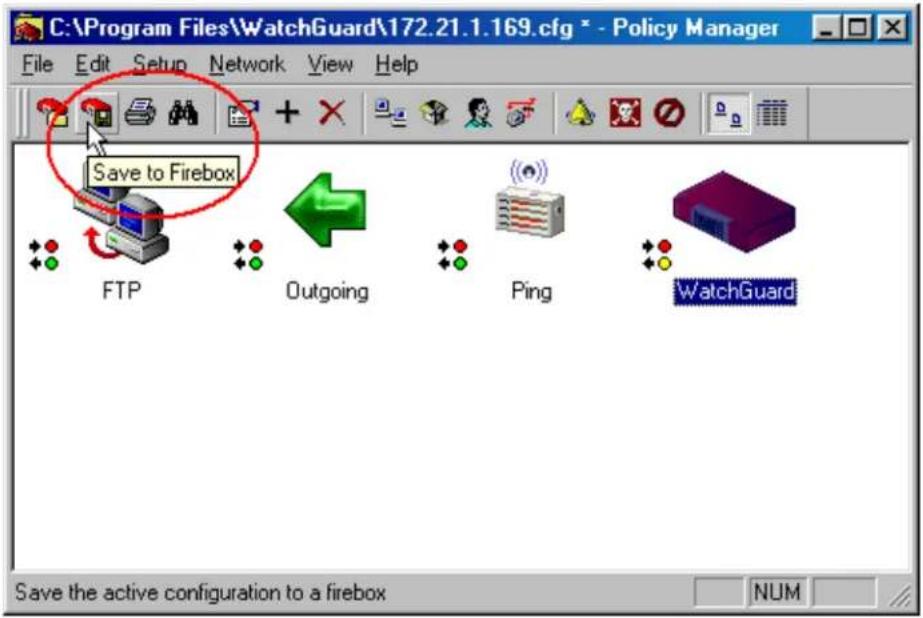
P-202H Plus v2 to NETSCREEN Tunneling
This page guides us to setup a VPN connection between P-202H Plus v2 and NETSCREEN. As the figure shown below, the tunnel between PC 1 and PC 2 ensures the packets flow between them are secure. To setup this VPN tunnel, the required settings for P-202H Plus v2 and NETSCREEN are explained in the following sections.
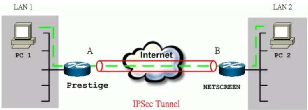
flowchart
graph LR
    subgraph LAN 1
        PC1["PC 1"] -->|A Prestige| Cloud["Internet"]
        Cloud -->|B NETSCREEN| PC2["PC 2"]
    end
    subgraph LAN 2
        PC2 -->|A Prestige| Cloud
        Cloud -->|B NETSCREEN| PC2
    end
    style LAN 1 fill:#f9f,stroke:#333
    style LAN 2 fill:#bbf,stroke:#333
The IP addresses we use in this example are as shown below.
| PC 1 | P-202H Plus v2 | NETSCREEN | PC 2 |
| 192.168.1.33 | LAN: 192.168.1.1 | LAN: 192.168.78.1 | 192.168.78.5 |
WAN: 202.132.154.1 WAN: 168.10.10.66
Note: The following configurations are supposed both two VPN gateways have fixed IP addresses. If one of VPN gateways uses dynamic IP, we enter 0.0.0.0 as the secure gateway IP address. In this case, the VPN connection can only be initiated from dynamic side to fixed side to update its dynamic IP to the fixed side. From this connection, the source IP is obtained and then update to the previous 0.0.0.0 field. However, if both gateways use dynamic IP addresses, it is no way to establish VPN connection at all.
1. Setup P-202H Plus v2
- Login P-202H Plus v2 by giving the LAN IP address of P-202H Plus v2 in URL field. Default LAN IP is 192.168.1.1, default password to login web configurator is 1234.
- Click Advanced, and click VPN tab on the left.
- On the SUMMARY menu, Select a policy to edit by clicking Edit.
- On the CONFIGURE-IKE menu, check Active check box and give a name to this policy.
- Select IPSec Keying Mode to IKE and Negotiation Mode to Main, as we configured in NETSCREEN.
- Source IP Address Start and Source IP Address End are PC 1 IP in this example. If a range of IP is used, please enter the start IP and the end IP. For example, 192.168.1.33 to 192.168.1.35.
- Destination IP Address Start and Destination IP Address End are PC 2 IP in this example. (the secure remote host)
- My IP Addr is the WAN IP of P-202H Plus v2.
- Secure Gateway IP Addr is the remote secure gateway IP, that is NETSCREEN WAN IP in this example.
- Select Encapsulation Mode to Tunnel.
- Check the ESP check box. (AH can not be used in SUA/NAT case)
- Select Encryption Algorithm to DES and Authentication Algorithm to MD5, as we configured in NETSCREEN.
- Enter the key string 12345678 in the Preshared Key text box, and click Apply.
See the screen shot:

If you use SMT management, the VPN configurations are as shown below.
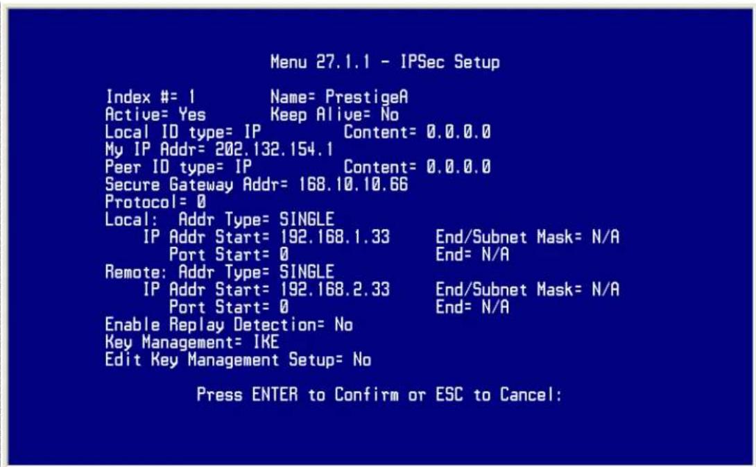
- Edit IKE settings by selecting Edit IKE Setup option in menu27.1.1 to Yes and then pressing 'Enter'.
- There are two phases for IKE:
In Phase 1, two IKE peers establish a secure channel for key exchanging.
In Phase 2, two peers negotiate general purpose SAs which are secure channels
for data transmission.

2. Setup NETSCREEN For VPN
- Configure NETSCREEN by using its web configurator.
- Login NETSCREEN by giving the LAN IP address of NETSCREEN in URL field
Create Local & Remote Secure Host:
- Click Address menu and click Trusted tab.
- Click New Address to add the local secure host (192.168.78.5 in this example) and give a name to this host address (Local Secure Host in this example). See the screen shown below.
Note: The Netmask field here for single IP is 255.255.255.255. Please do not enter the wrong netmask, otherwise, VPN can not be established correctly.
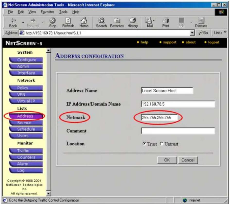
- Click OK to save it.
- Click New Address to add the remote secure host (192.168.1.33 in this example) and give a name to this host address (Remote Secure Host in this example). See the screen shown below.
Note: The Netmask field here for single IP is 255.255.255.255. Please do not enter the wrong netmask, otherwise, VPN can not be established correctly.
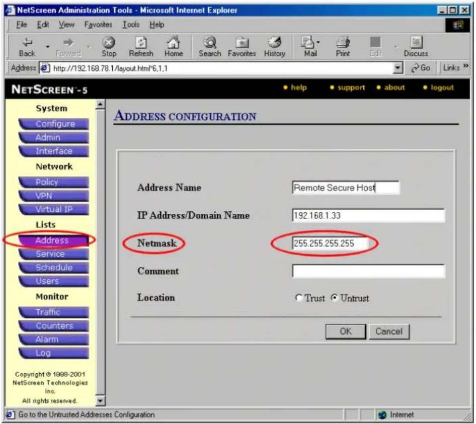
- Click OK to save it.
Create Outgoing & Incoming VPN Policy:
- Click Policy menu and click Outgoing tab.
- Click New Policy to configure the outgoing VPN policy.
- Give a name to the policy.
- Select the Local Secure Host that we configured above as the Source Address.
- Select the Remote Secure Host that we configured above as the Destination Address.
- Select ANY as the Service.
- For the rest settings please refer to the following screen shot. And click OK to save.

-
Click Policy menu and click Incoming tab.
-
Click New Policy to configure the incoming VPN policy.
- Give a name to the policy.
- Select the Remote Secure Host that we configured above as the Source Address.
- Select the Local Secure Host that we configured above as the Destination Address.
- Select ANY as the Service.
- For the rest settings please refer to the following screen shot. And click OK to save.
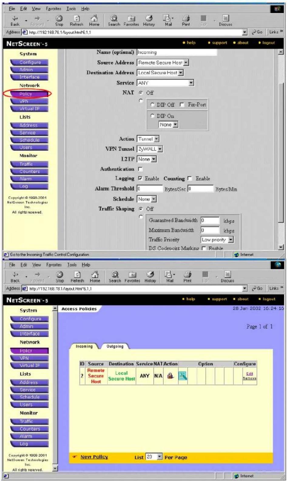
Create Phase 1 Proposal: Note that all phase 1 and phase 2 settings in NETSCREEN must be consistent with P-202H Plus v2.
- Click VPN menu and click P1 Proposal tab.
- Click New Phase 1 Proposal to create phase 1 proposal.
- Give a Name for this proposal, for example P-202H Plus v2.
- Select Preshare as the Authentication Method.
- Select Group 1 as DH Group.
- Select DES-CBC as Encryption Algorithm.
-
Select MD5 as Hash Algorithm.
-
Enter 3600 in Lifetime field, check Sec checkbox. See the screen shot below.
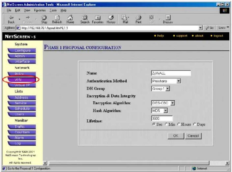
Create Phase 2 Proposal:
- Click VPN menu and click P2 Proposal tab.
- Click New Phase 2 Proposal to create phase 2 proposal.
- Check Encryption (ESP) checkbox and select DES-CBC and MD5 as the Encryption Algorithm and the Authentication Algorithm. See the
screenshot.
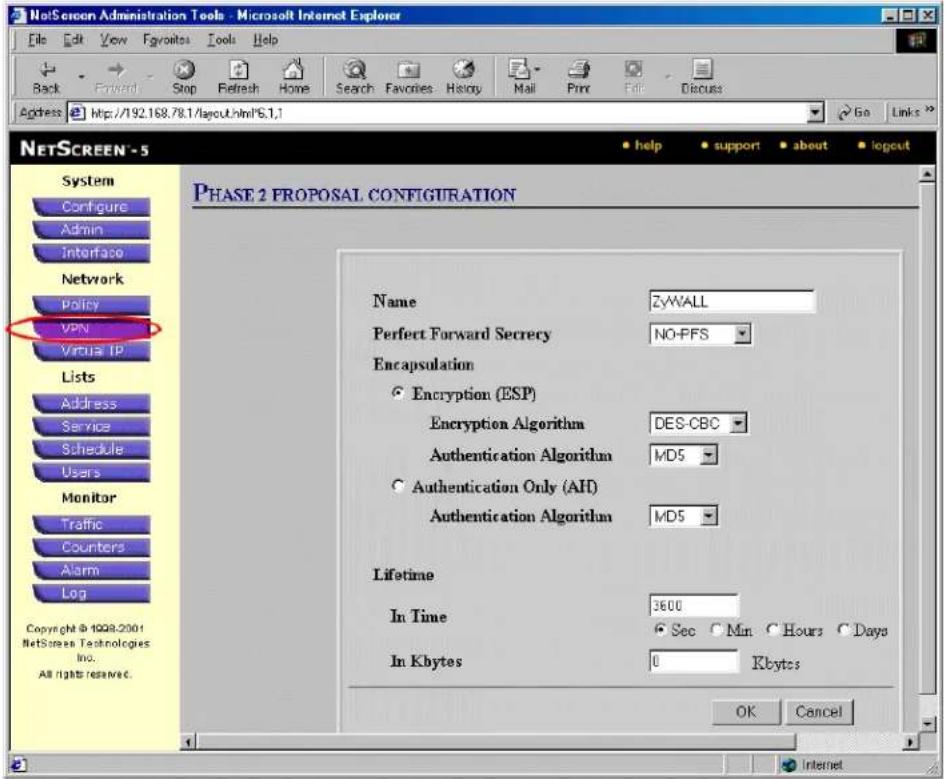
Create VPN Gateway:
- Click VPN menu and click Gateway tab.
- Click New Remote Tunnel Gateway to add the local VPN gateway, i.e., NETSREEN.
- Give a name to this gateway, for example NETSCREEN.
- Click Static IP Address as for this example.
- Enter WAN IP of NETSCREEN in the IP Address field.
-
Select P-202H Plus v2 that we configure above as the Phase 1 Proposal.
-
Enter 12345678 as the Preshared Key and click OK to save. See the screenshot.
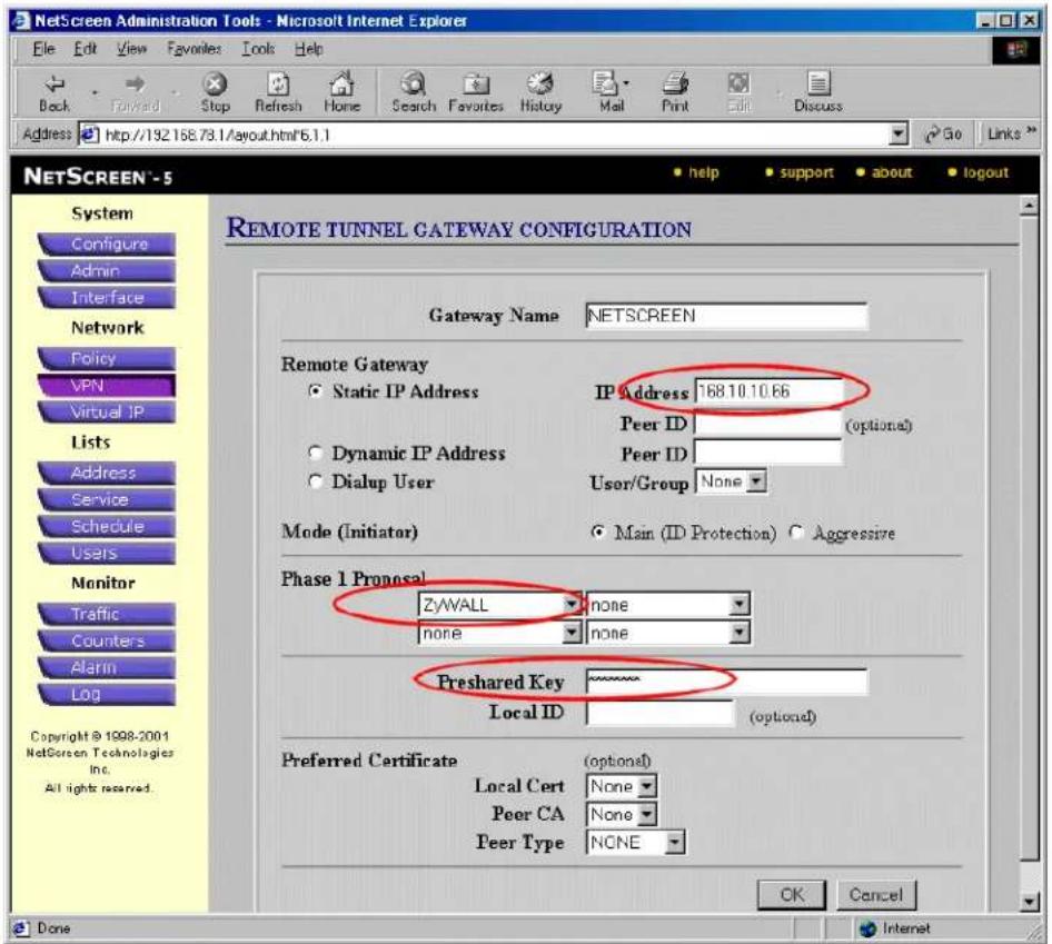
- Click New Remote Tunnel Gateway to add the remote VPN gateway, i.e., P-202H Plus v2.
- Give a name to this gateway, for example P-202H Plus v2.
- Click Static IP Address as for this example.
- Enter WAN IP of P-202H Plus v2 in the IP Address field.
-
Select P-202H Plus v2 that we configure above as the Phase 1 Proposal.
-
Enter 12345678 as the Preshared Key and click OK to save. See the screenshot.
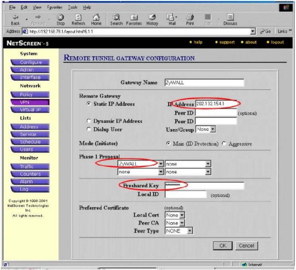
Create AutoKey IKE:
- Click VPN menu and click AutoKey IKE tab.
- Click New AutoKey IKE Entry to add the entry for the local gateway, i.e., NETSCREEN.
- Select NETSCREEN as the Remote Gateway Tunnel Name.
- Select P-202H Plus v2 as Phase 2 Proposal and click OK to save. See the screen shot.
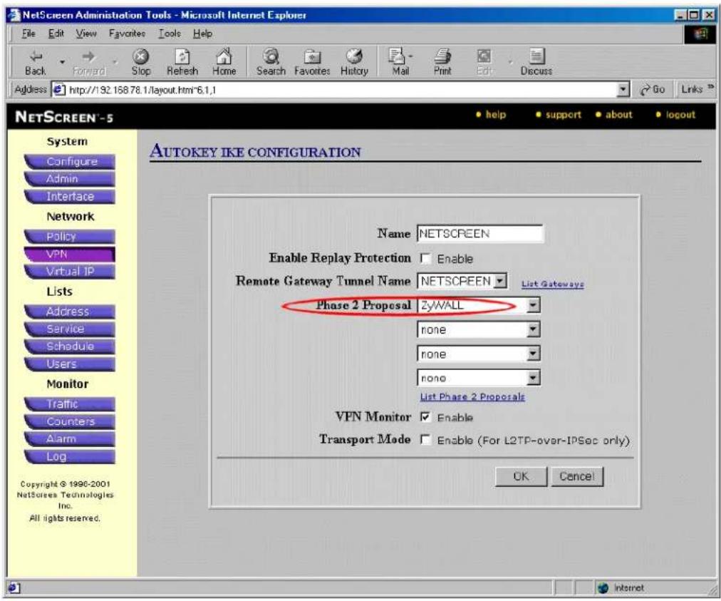
- Click VPN menu and click AutoKey IKE tab.
- Click New AutoKey IKE Entry to add the entry for the remote gateway, i.e., P-202H Plus v2.
- Select P-202H Plus v2 as the Remote Gateway Tunnel Name.
- Select P-202H Plus v2 as Phase 2 Proposal and click OK to save. See the screen shot.
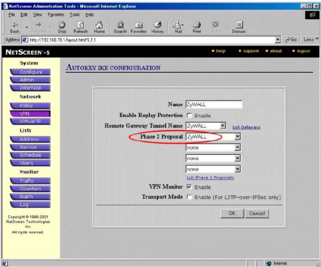
- After all above settings have been finished, you can start to access the remote secure PC. If the VPN is established successfully, you can see the traffic flow from the Traffic Log by clicking Log menu. See the following screen shot.
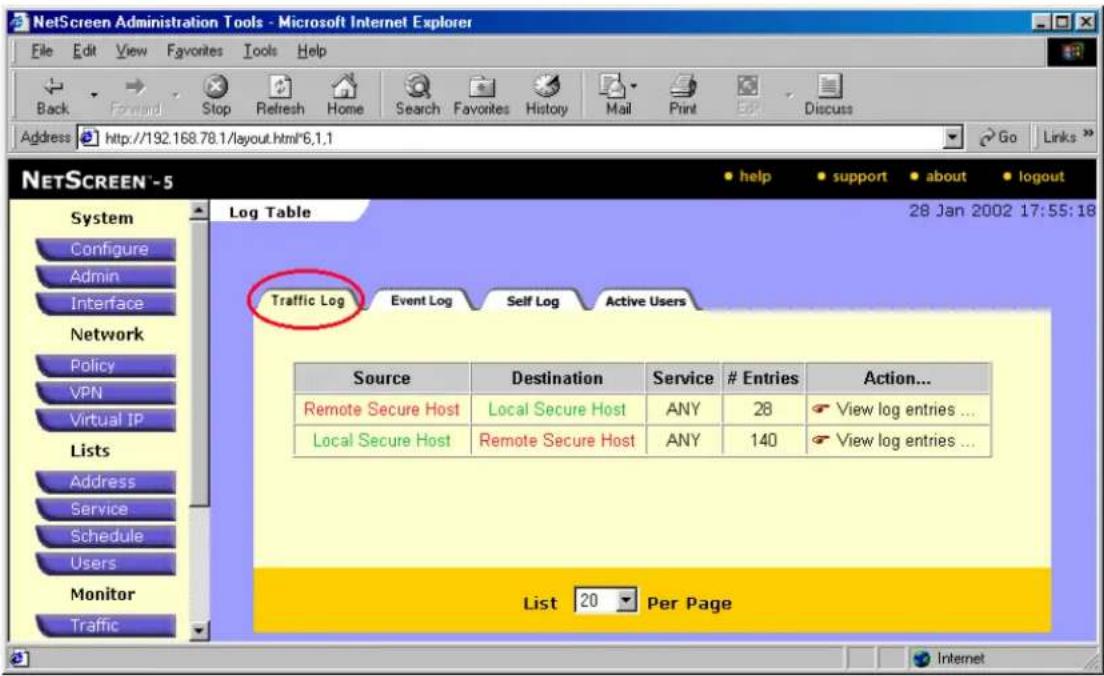
You can also see the current active user from the Active Log by clicking Log menu. See the following screen shot.
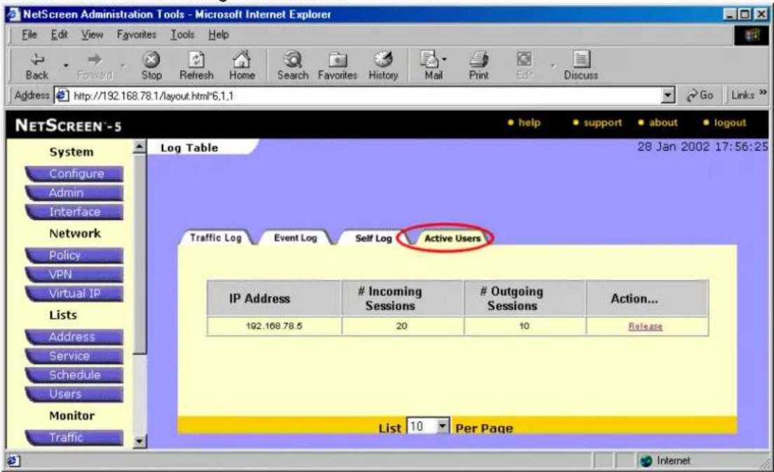
3. P-202H Plus v2 vs 3rd Party VPN Software
Checkpoint VPN to P-202H Plus v2 Tunneling
This page guides us to setup a VPN connection between Checkpoint VPN and P-202H Plus v2 router.
As the figure shown below, the tunnel between P-202H Plus v2 and Checkpoint ensures the packets flow between them are secure. Because the packets go through the IPSec tunnel are encrypted. To setup this VPN tunnel, the required settings for the software and P-202H Plus v2 are explained in the following.
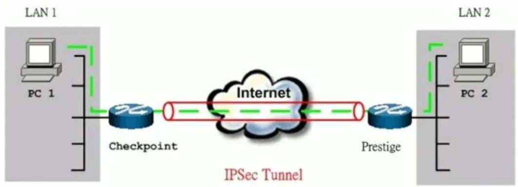
flowchart
graph LR
    subgraph LAN 1
        PC1["PC 1"]
        CheckPoint["Checkpoint"]
    end
    subgraph LAN 2
        PC2["PC 2"]
        Prestige["Prestige"]
    end
    CheckPoint --> Internet["Internet"]
    Prestige --> Internet
    IPSec["Tunnel"] --> Internet
    IPSec --> IPSec
The IP addresses we use in this example are as shown below.
| LAN 1 | Checkpoint | P-202H Plus v2 | LAN 2 |
| 172.16.16.0/24 | 62.2.237.177 | 217.20.195.73 | 192.168.99.0/24 |
1. Setup P-202H Plus v2
Remove default fliter rule from Menu 3.1
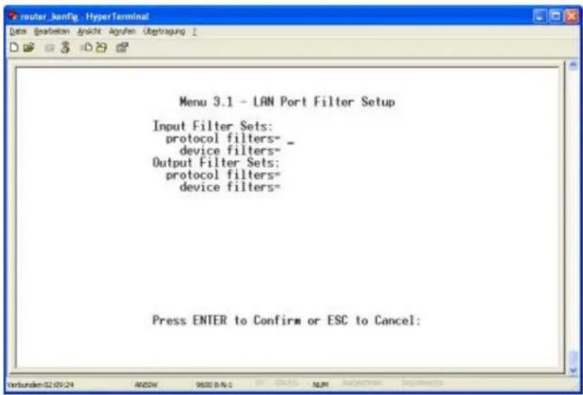
Edit LAN segment of P-202H Plus v210. In this example, we setup P-202H Plus v210 as DHCP server, and it's LAN IP address is 192.168.99.1.
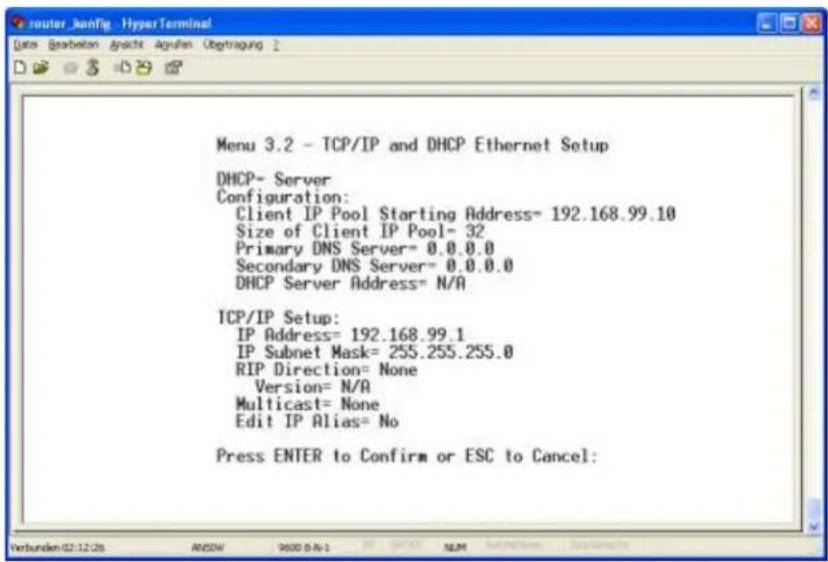
Edit Internet Access of P-202H Plus v210.
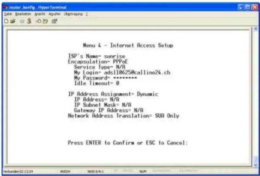
In SMT menu 27, create a VPN rule like following.
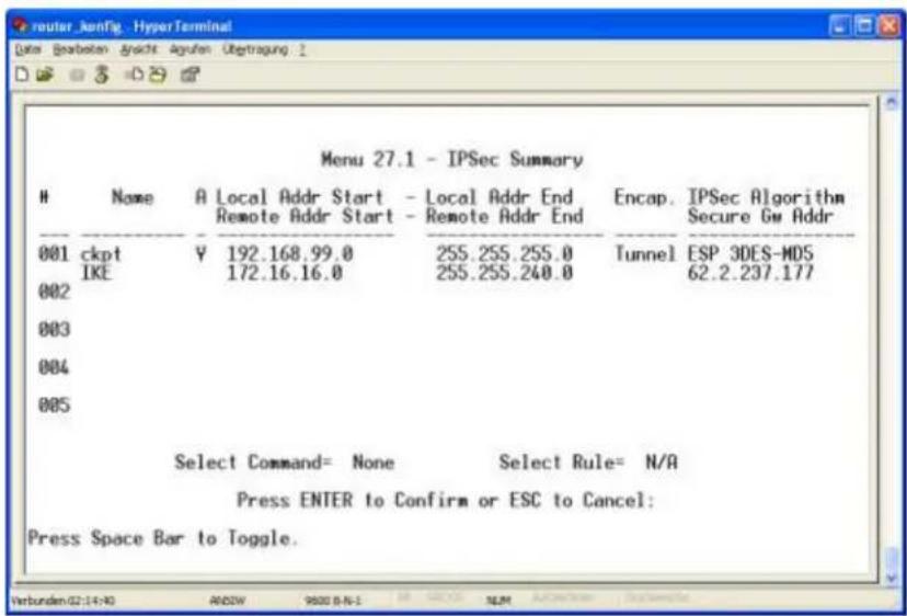
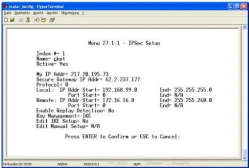
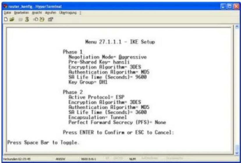
2. Setup Checkpoint VPN
Creating Network objects.
Click on New/Network, define the LAN segment of P-202H Plus v2. Select Locationa as External.
(Note-Internal and external refer to whether this network is protected behind the Checkpoint or not.)
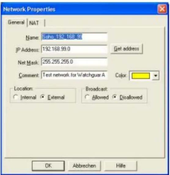
Define the LAN segment of Checkpoint. Select Location as Internal.
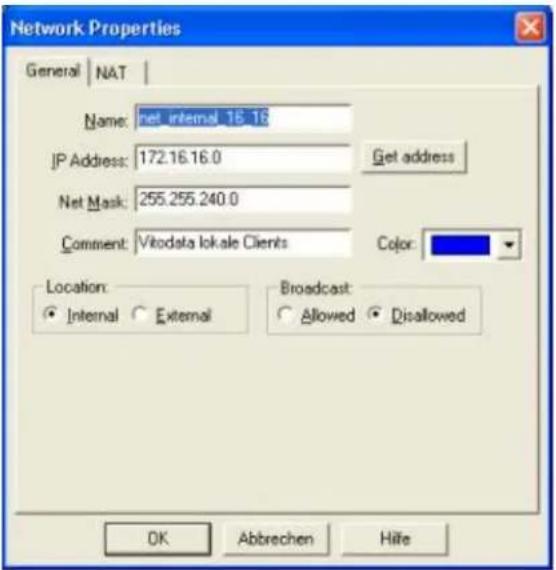
If there are more than one network would like to utilize the VPN tunnel. You can merge the networks into one group.
- Go to Manage/Network Objects.
- Click on New/Group
• Fill in the properties for the group objects as shown below.
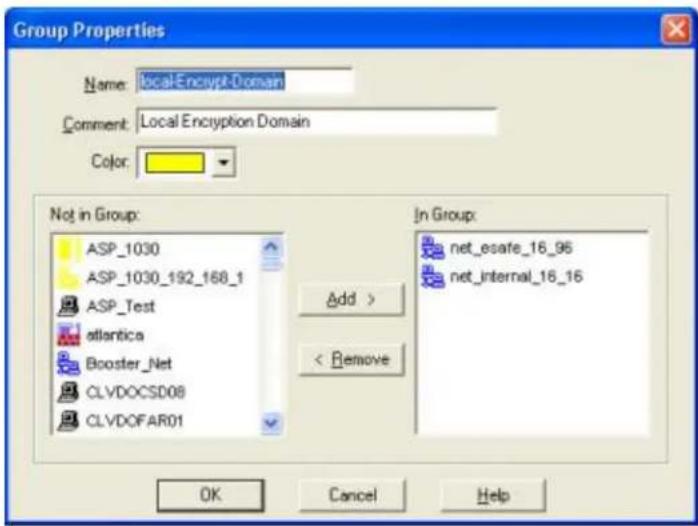
Creating VPN Objects
Define P-202H Plus v2 box as a tunnel end point. (Name: SOHO_TEST)
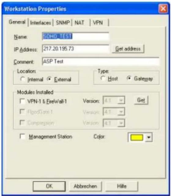
Select VPN tab to define the protected domain of ZW, and the Encryption schemes used by the tunnel.
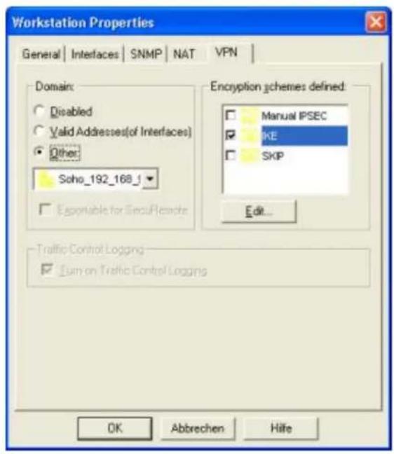
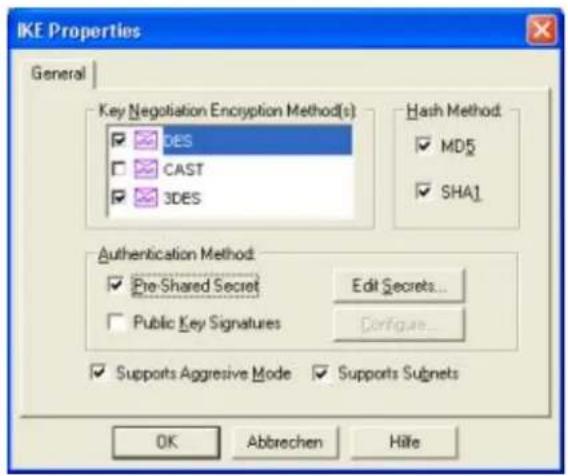
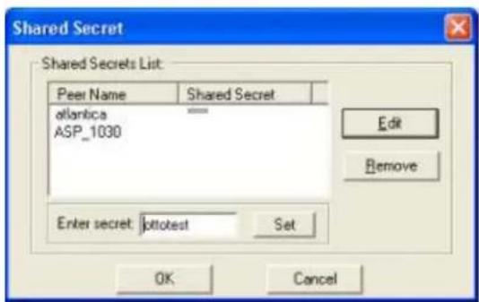
Define checkpoint box as a tunnel endpoint.
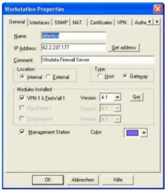
Select VPN tab to define the protected domain of Checkpoint, and the Encryption schemes used by the tunnel.
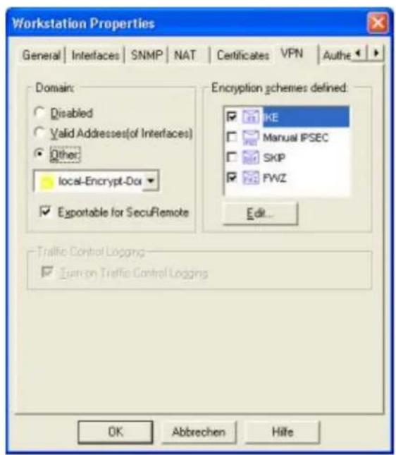
Choose IKE and press Edit... to edit the Phase1 parameters and pre-shared key.
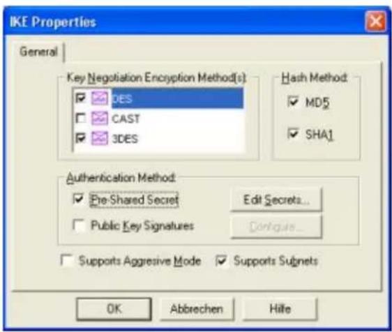
Edit pre-shared key by selecting Pre-Shared Secret in Authentication Method. Choose Pre-Shared Secret then press Edit-Secretes...
Select SOHO_TEST as peer, and input the pre-shared key.
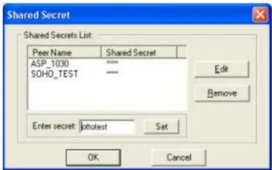
Define VPN policy.
Create a new rule at or near the top of the policy. This rule should include both encryption domains as both source and destination and the action should be encrypt as shown below.
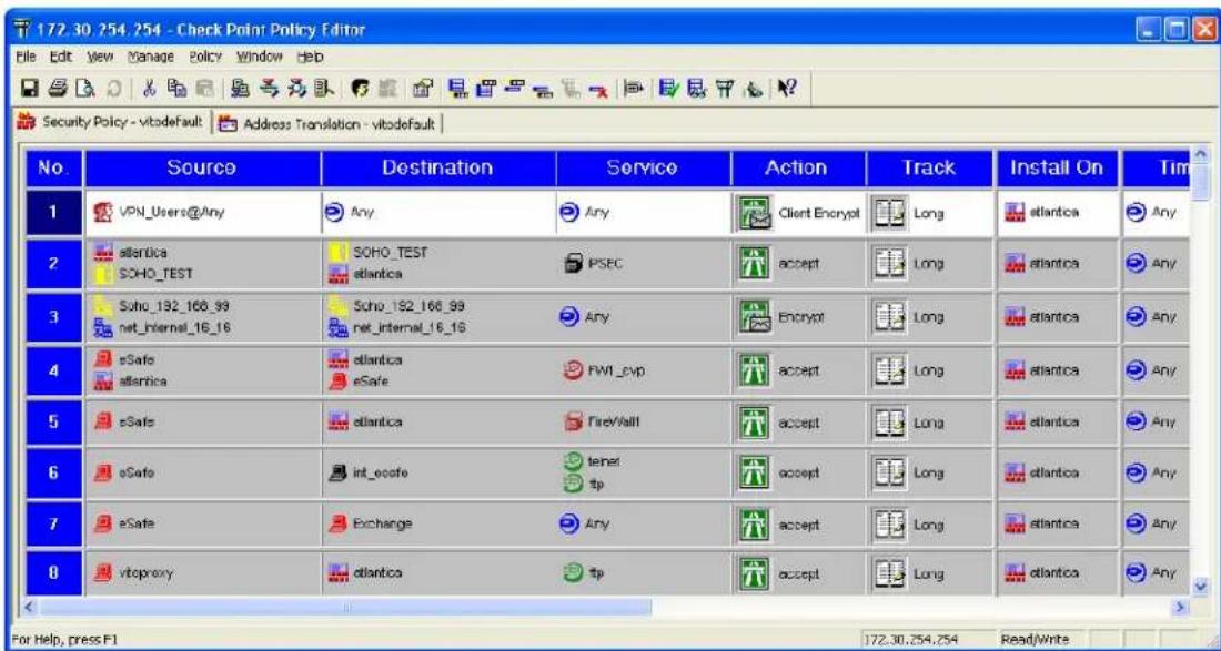
Double click on the "encrypt" action to edit the encryption properties. Select IKE as the form of encryption, and click on edit and select the Phase 2 parameters.
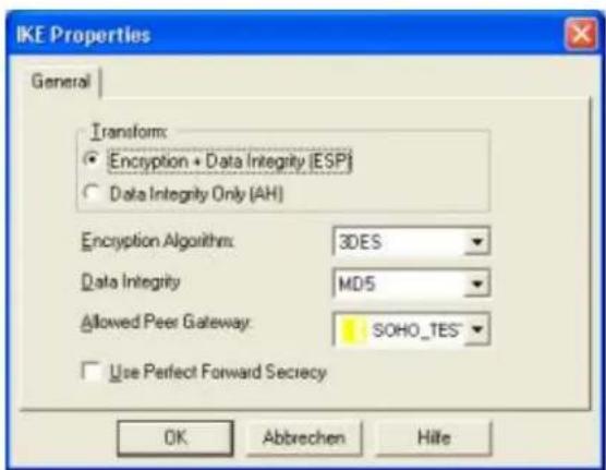
WIN2K VPN to P-202H Plus v2
This page guides us to setup a VPN connection between the WIN2K VPN software and P-202H Plus v2 router. There will be several devices we need to setup for this case. They are WIN2K VPN software and P-202H Plus v2 router.
As the figure shown below, the tunnel between PC 1 and P-202H Plus v2 ensures the packets flow between them are secure. Because the packets go through the IPSec tunnel are encrypted. To setup this VPN tunnel, the required settings for WIN2K and P-202H Plus v2 are explained in the following sections. As the red pipe shown in the following figure, the tunneling endpoints are WIN2K and P-202H Plus v2.
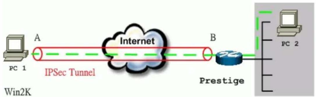
flowchart
graph LR
    A["PC 1"] -->|A| B["Internet"]
    B -->|B| C["Prestige"]
    C --> D["PC 2"]
    style A fill:#f9f,stroke:#333
    style B fill:#ccf,stroke:#333
    style C fill:#cfc,stroke:#333
    style D fill:#fcc,stroke:#333
The IP addresses we use in this example are as shown below.
| PC 1 | P-202H Plus v2 | PC2 |
| 172.21.1.232 | LAN: 192.168.1.1WAN: 172.21.1.252 | 192.168.1.33 |
1. Setup WIN2K VPN
- Create a custom MMC console
- From Windows desktop, click Start, click Run, and in the Open textbox type MMC. Click OK.
- On the Console window, click Add/Remove Snap-In.
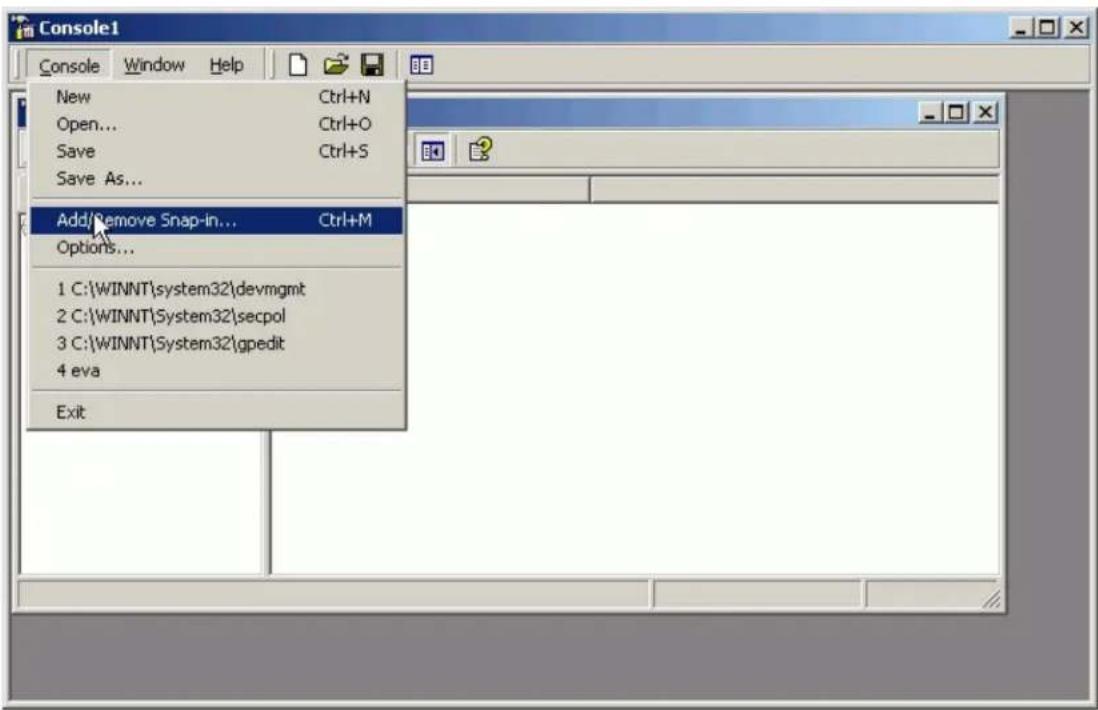
- In the Add/Remove Snap-In dialog box, click Add.
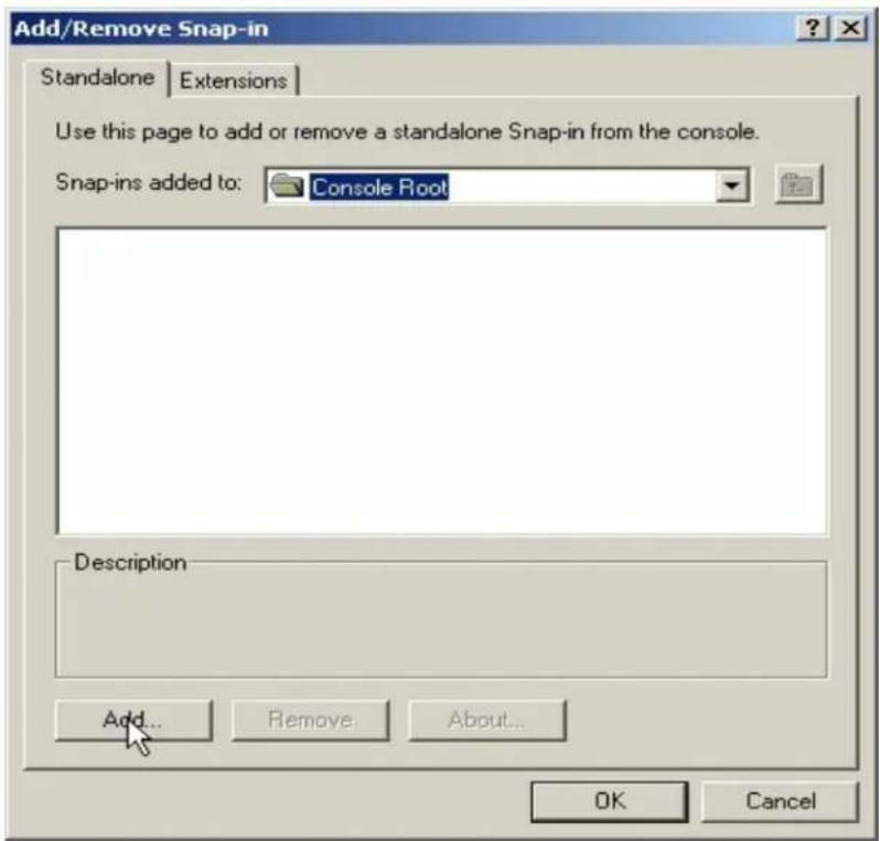
- In the Add Standalone Snap-in dialog box, click Computer Management, and then click Add.
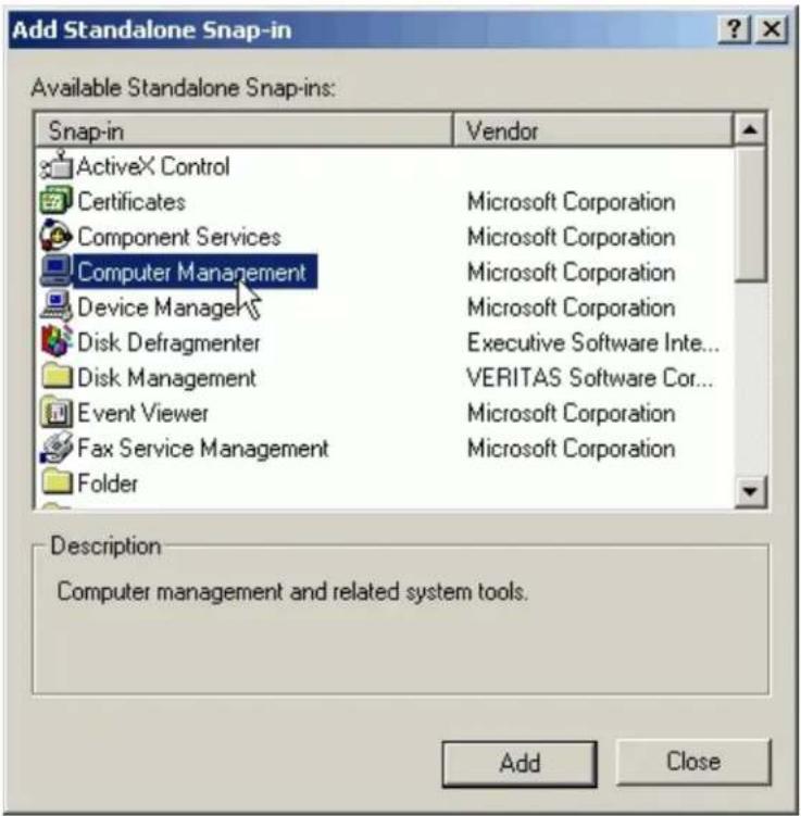
- Verify that Local Computer (default setting) is selected, and click Finish.
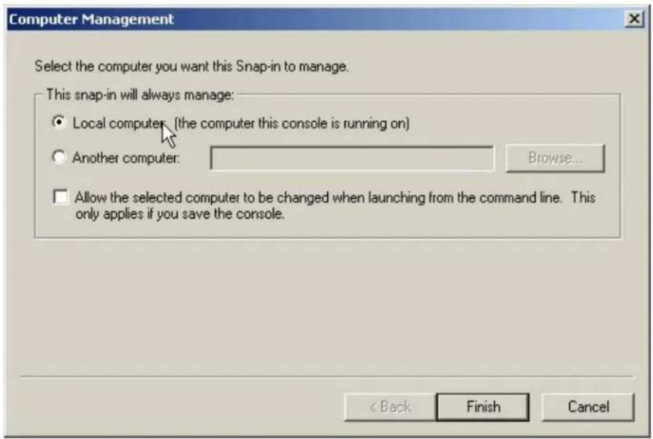
- In the Add Standalone Snap-in dialog box, click Group Policy, and then click Add.
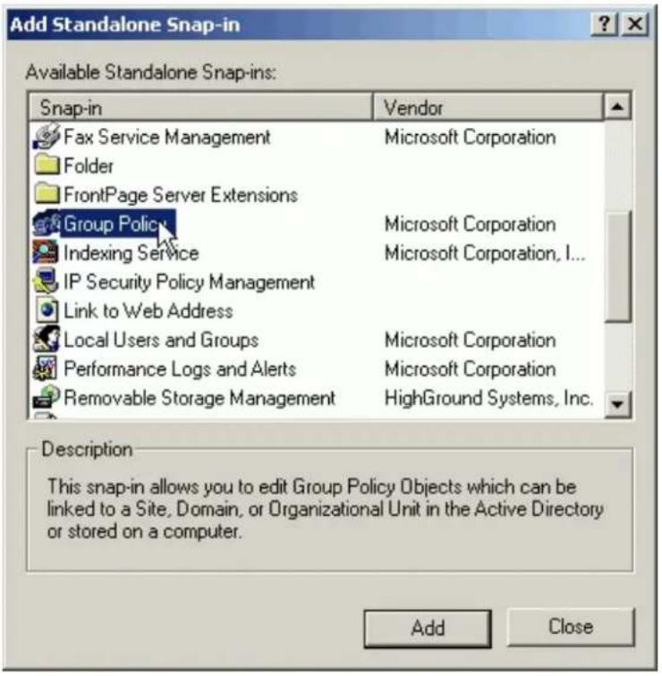
- Verify that Local Computer (default setting) is selected in the Group Policy Object dialog box, and then click Finish.
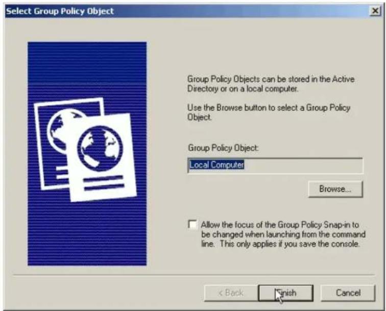
- In the Add Standalone Snap-in dialog box, click Certifications, and then click Add.
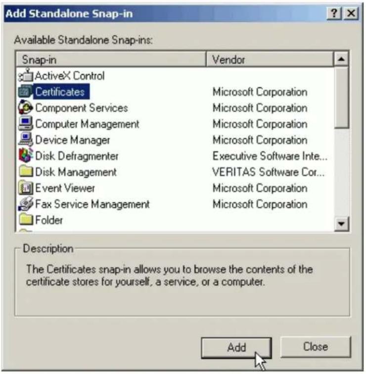
- In the Certificates snap-in dialog box, select Computer account, and click Next.
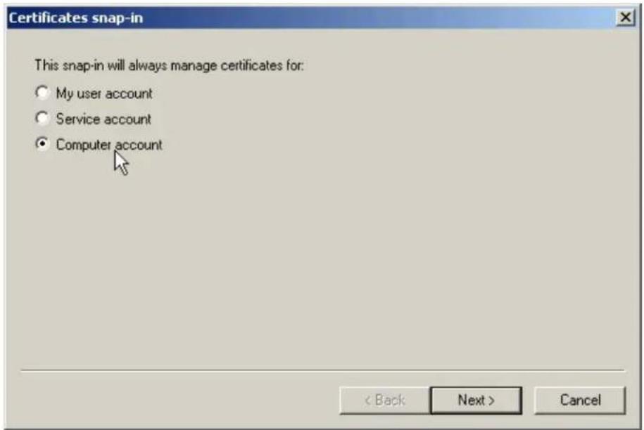
- Verify that Local Computer (default setting) is selected, and click Finish.
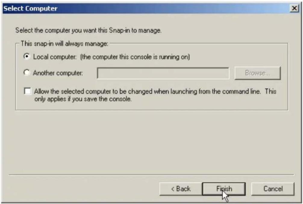
- Click Close to close the Add Standalone Snap-in dialog box.
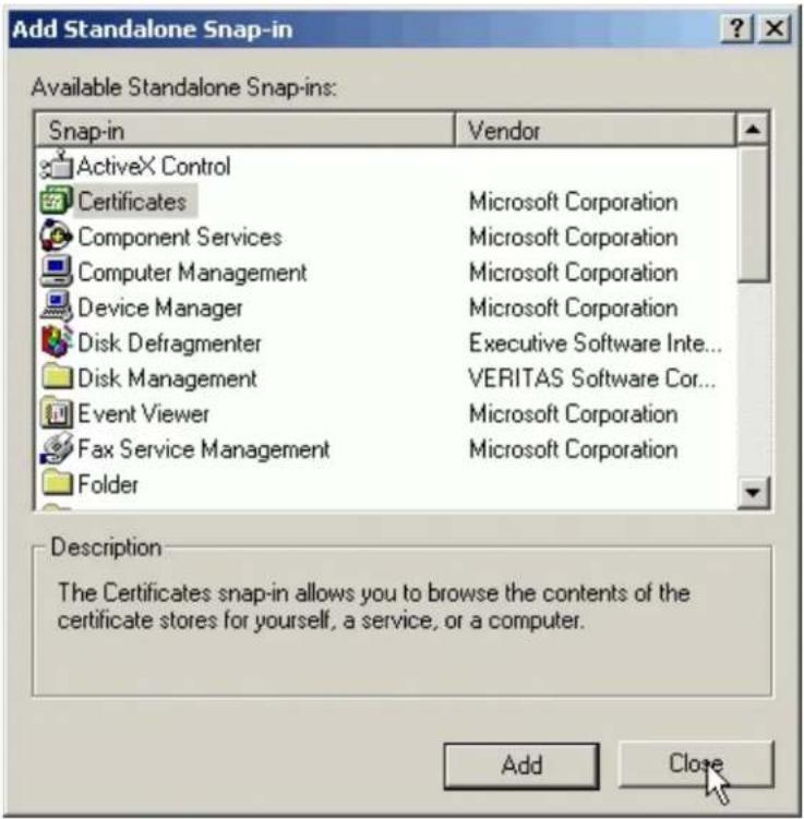
- Click OK to close the Add/Remove Snap-in dialog box.
![Console1 - [Console Root] Console Window Help Action View Favorites Tree Favorites Console Root + Computer Management (Local) + Local Computer Policy + Certificates (Local Computer) Name + Computer Management (Local) + Local Computer Policy + Certificates (Local Computer)](/content/2026/02/353416/images/c3e14a1b09c6d4999f03a57c43bc0e6505c5b0adb2e165f106efd30a5e6ae972.jpg)
- Create IPSec Policy
Typically, Windows 2000 gateway is not a member of a domain, so a local IPSec policy is created. If your Windows 2000 gateway is a member of a domain that already exists an local IPSec policy. In this case, you can create an Organization Unit (OU) in Active Directory to make your WIN2K as a member of this OU by assigning the IPSec policy to the Group Policy Object (GPO) of this OU. For more information, please refer to the Assigning IPSec Policy section of Windows 2000 online help.
- From Windows desktop, click Start, click Run, and in the Open textbox type SECPOL.MSC. Click OK.
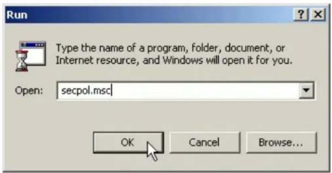
- Right click IP Security Policies on Local Machine, and then click Create IP Security Policy.
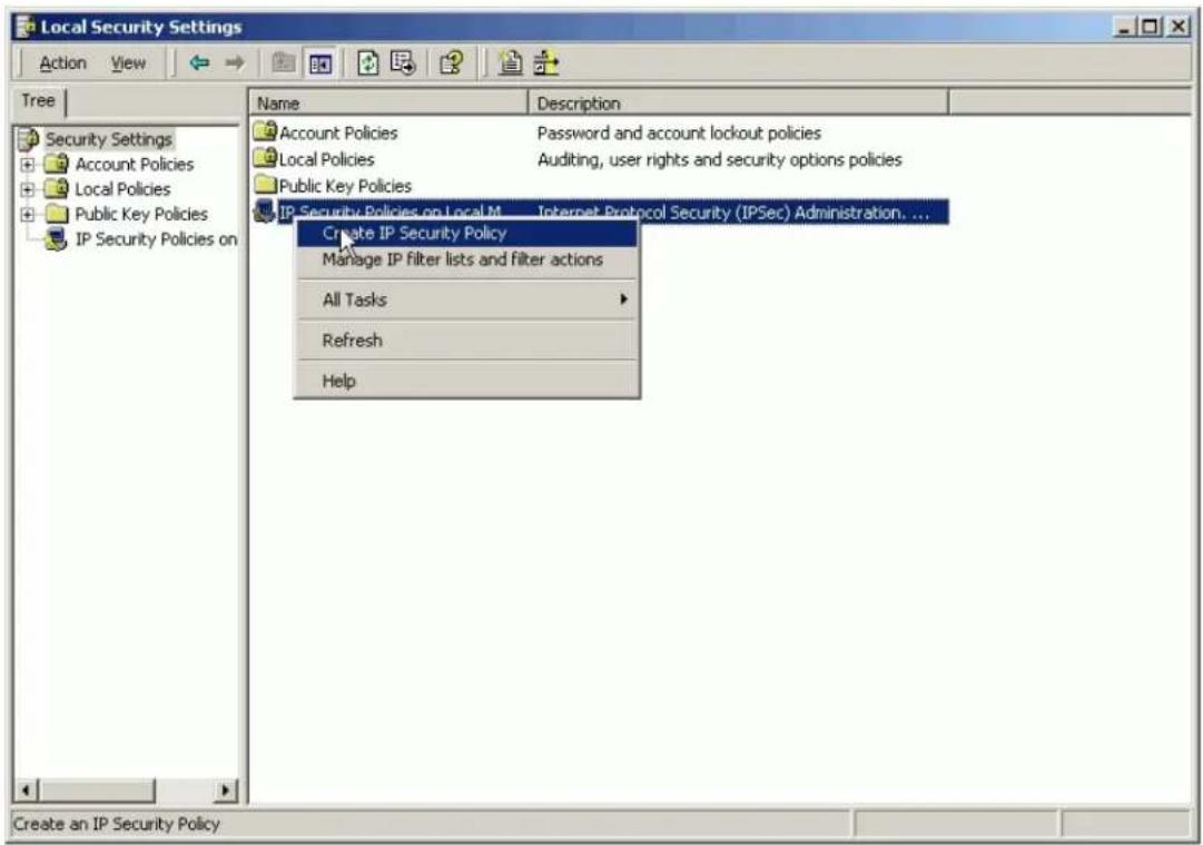
- Click Next, and type a name for your policy. For example, WIN2K to P-202H Plus v2 Tunnel.
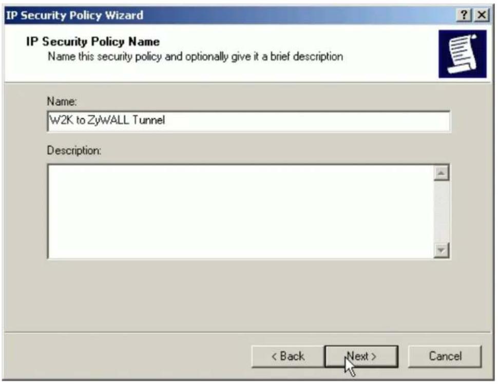
- Uncheck Active the default response rule check box, and click Next.
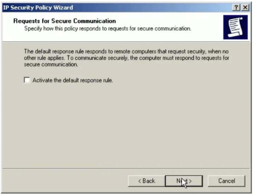
- Keep the Edit properties check box selected and click Finish.
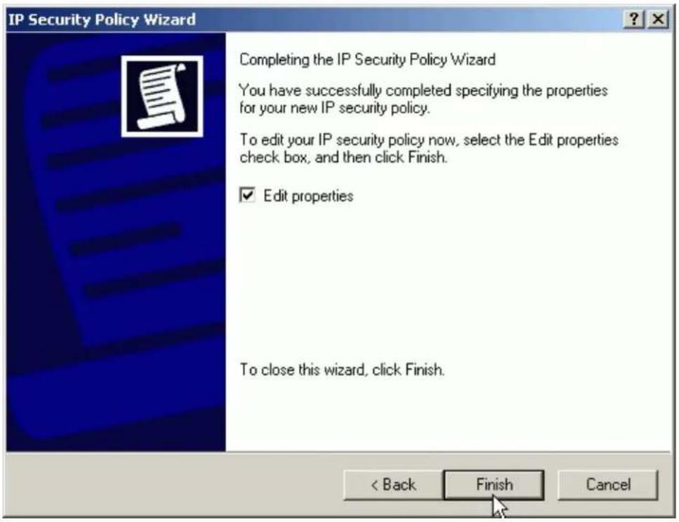
- A dialog window will bring up for you to configure two filter rules for this policy.
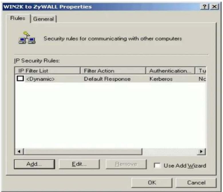
Note: The IPSec policy is created with default IKE main mode (phase 1) on the General tab. Please check details by clicking the Advanced on this tab.
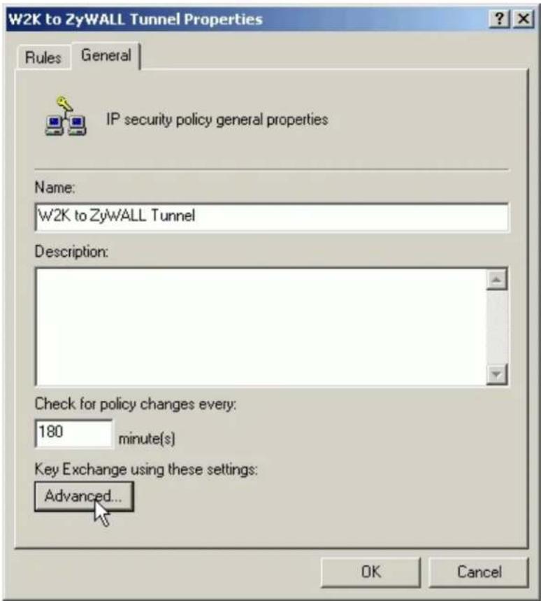
The IPSec tunnel consists of two rules, each of which specifies a tunnel endpoint. Because there are two endpoints so we need two filter rules. One is for the direction from PC 1 to PC 2 (endpoint is P-202H Plus v2), and the other is from PC 2 to PC 1 (endpoint is WIN2K). In each rule, a source IP and destination IP for local and remote VPN clients (PC 1 or PC 2) are required. See the guides below.
- Build a Filter List from PC 1 to PC 2
- In policy properties, uncheck Use Add Wizard check box, and click Add to create a new rule.
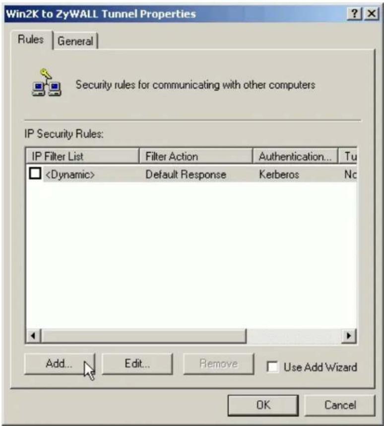
- On the IP Filter List tab, click Add.
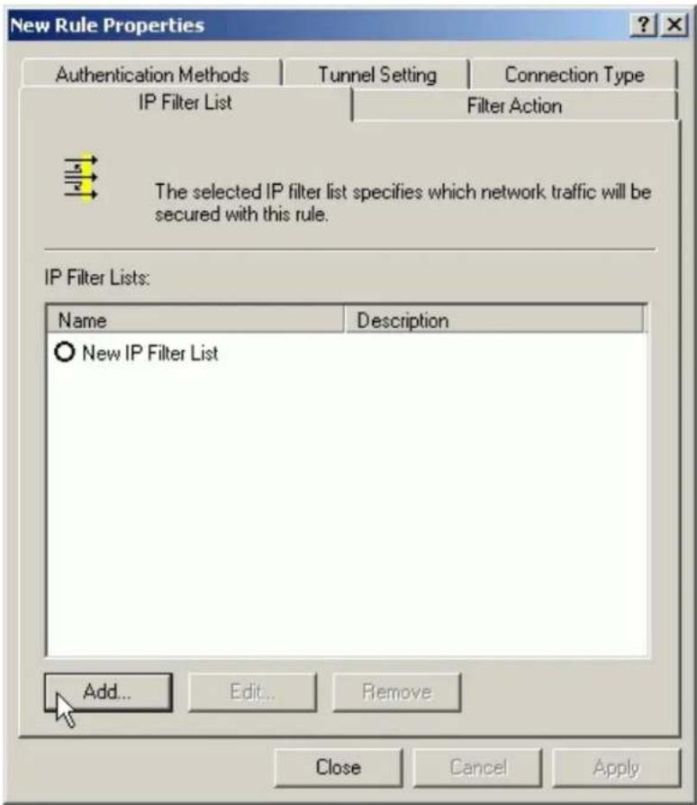
- Type a name for the filter list (e.g., WIN2K to P-202H Plus v2), uncheck Use Add Wizard check box, and click Add.

- In the Source address, choose A specific IP Address, and enter the IP address of PC 1
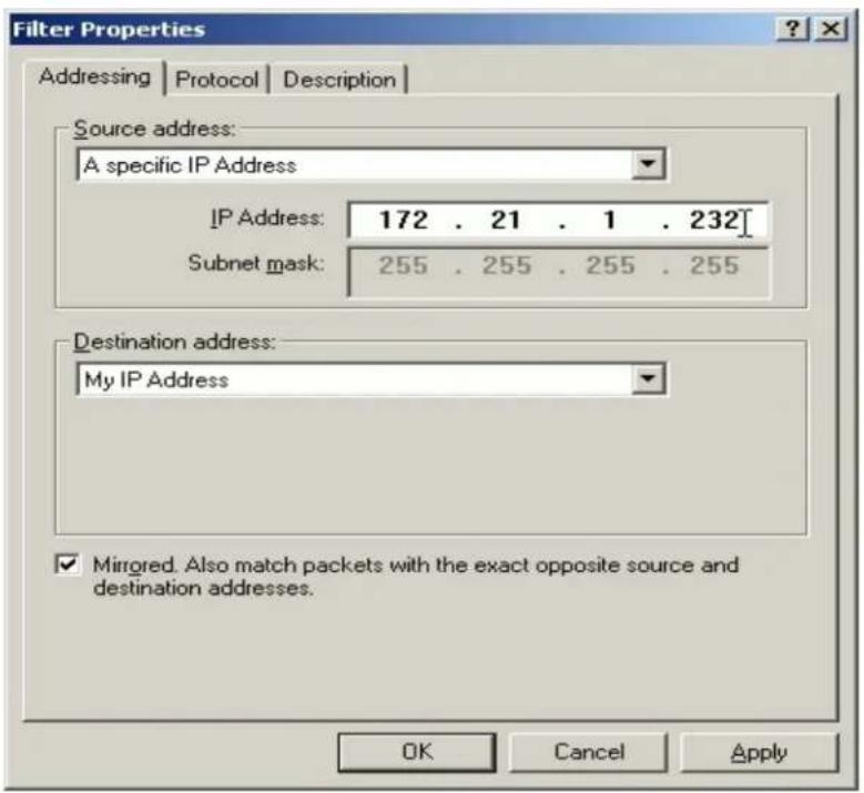
- In the Destination address, choose A specific IP Address, and enter the IP address of PC 2
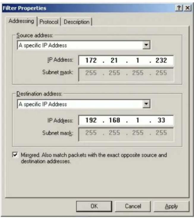
- Uncheck Mirror check box.
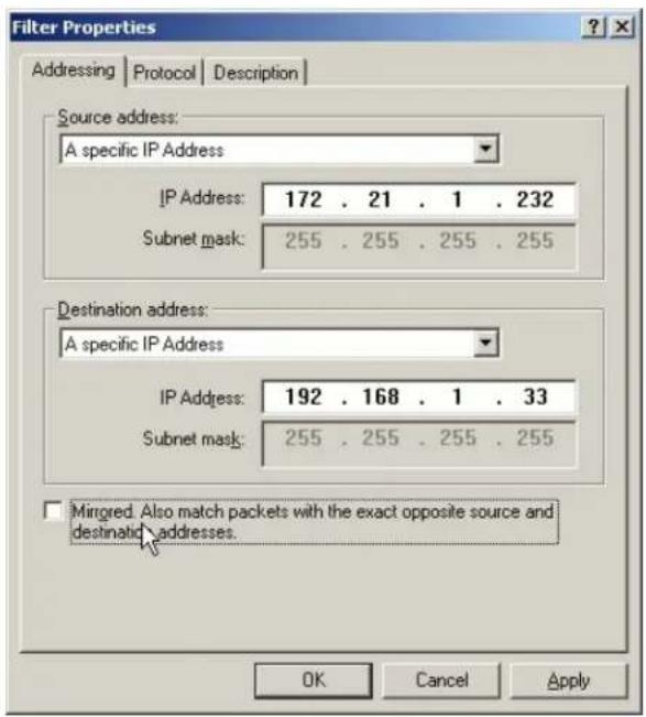
- On the Protocol tab, leave the protocol type to Any, because IPSec tunnels do not support protocol-specific or port specific filters.
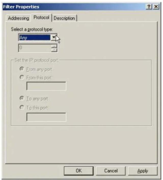
- On the Description tab, you can give a name for this filter list. The filter name is displayed in the IPSec monitor when the tunnel is active.
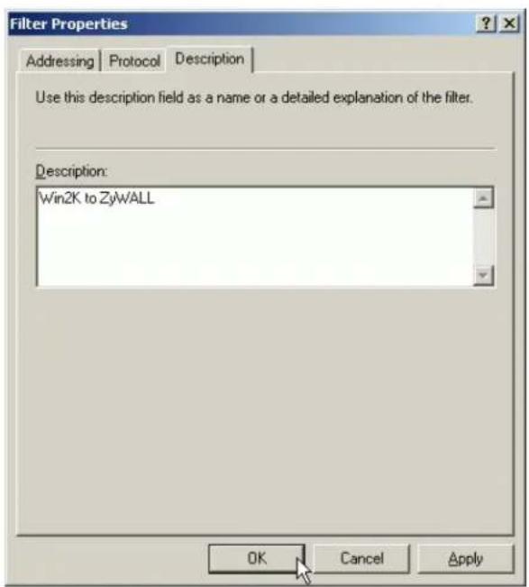
- Click OK and Close to close the windows.

- Build a Filter List from PC 2 to PC 1
- On the IP Filter List tab, click Add.
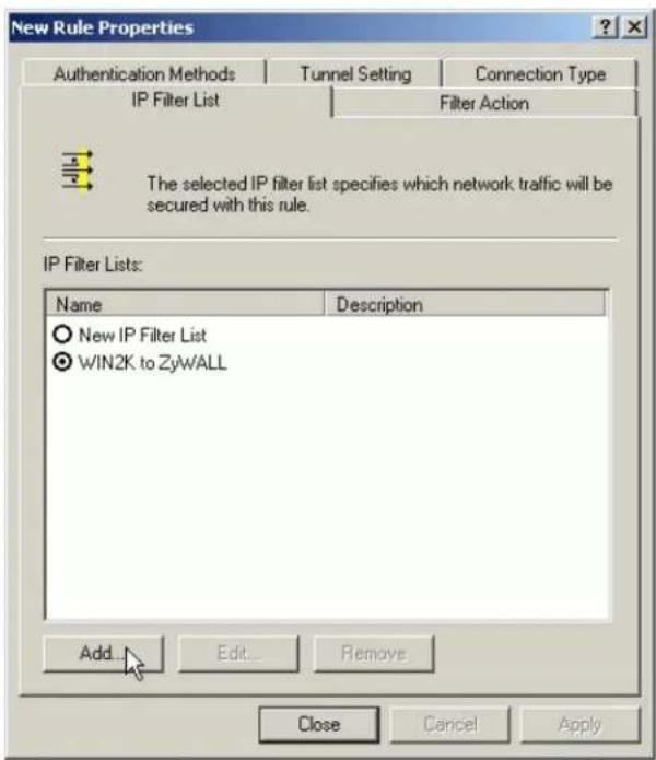
- Type a name for the filter list (e.g., P-202H Plus v2 to WIN2K), uncheck Use Add Wizard check box, and click Add.
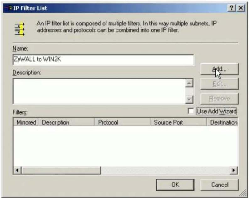
- In the Source address, choose A specific IP Address, and enter the IP address of PC 2
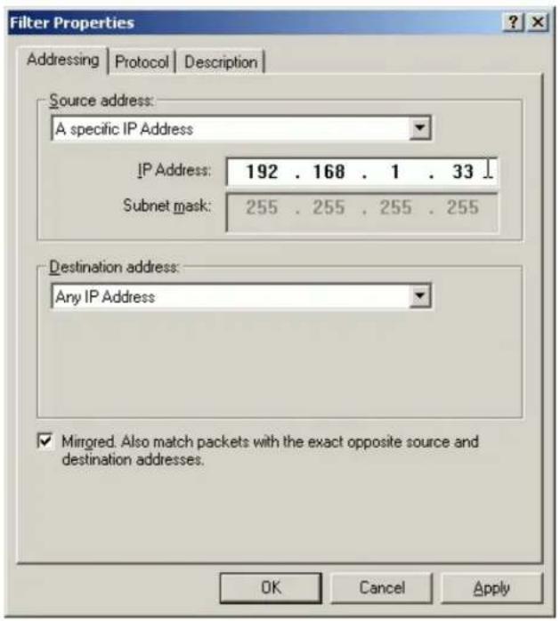
- In the Destination address, choose A specific IP Address, and enter the IP address of PC 1
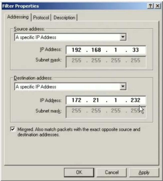
- Uncheck Mirror check box.
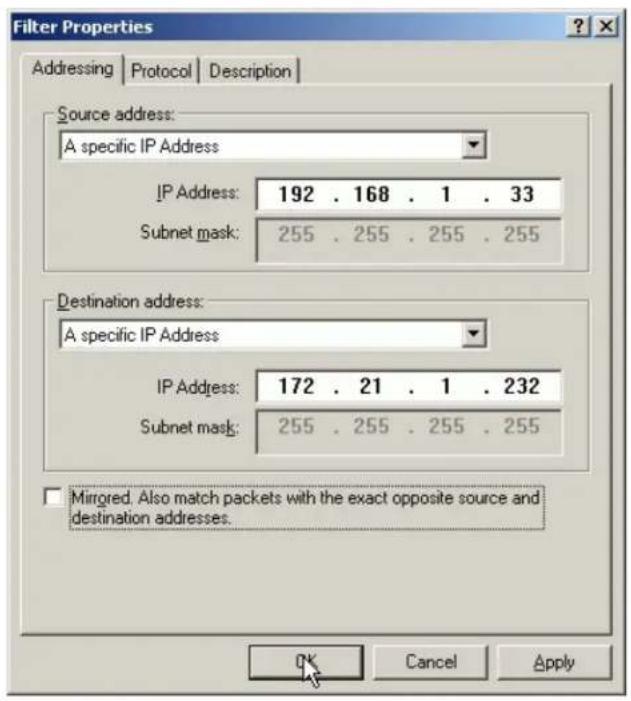
- On the Protocol tab, leave the protocol type to Any, because IPSec tunnels do not support protocol-specific or port specific filters.
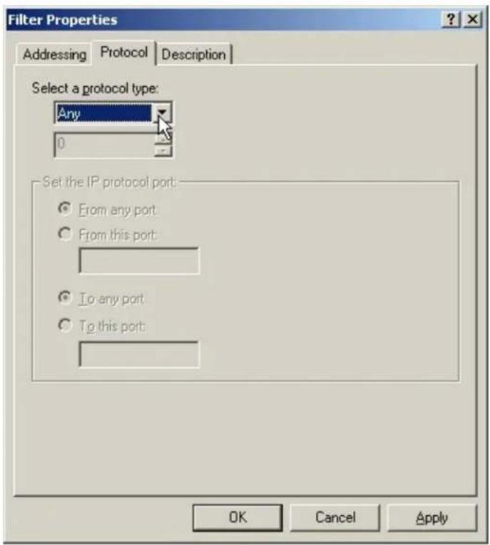
- On the Description tab, you can give a name for this filter list. The filter name is displayed in the IPSec monitor when the tunnel is active.
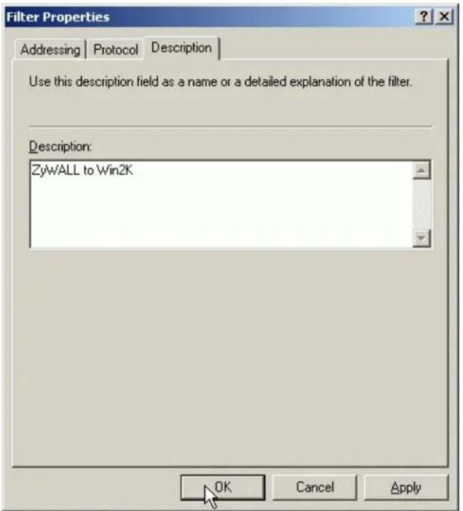
- Click OK and Close to close the windows.
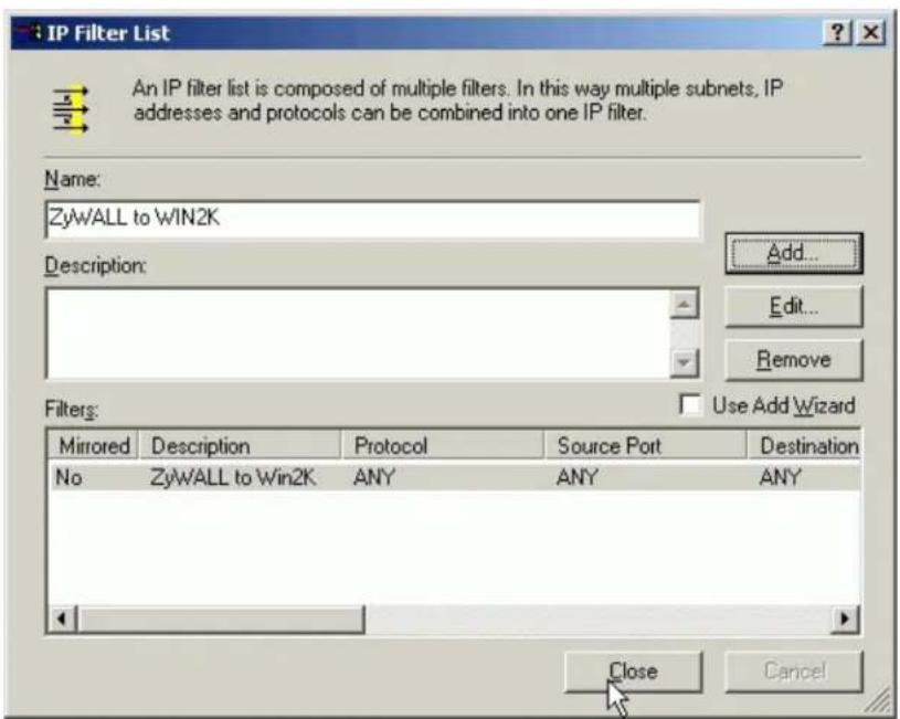
- Configure a Rule for PC 1 to PC 2 tunnel
- Select the first filter list you created above from the IP Filter List. For example, WIN2K to P-202H Plus v2.
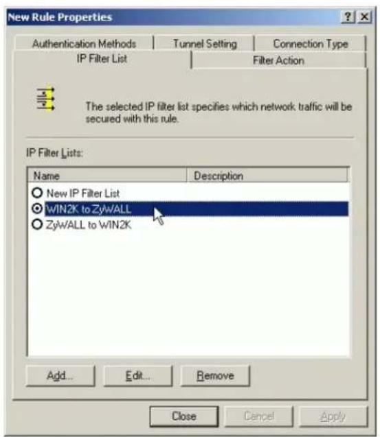
- Click Tunnel Setting tab, enter the remote endpoint. For this filter list, the remote IPSec endpoint is P-202H Plus v2.
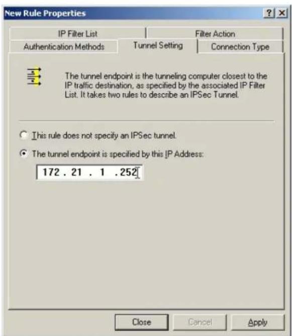
- Click Connection Type tab, click All network connections (or click LAN connections if your WIN2K does not connect to ISP but LAN). In our example, we choose All network connections.
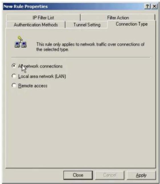
- Click Filter Action tab, uncheck Use Add Wizard check box, and click Add.
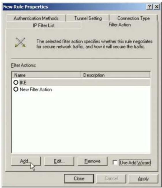
- Leave Negotiate security as checked, and uncheck Accept unsecured communication, but always respond using IPSec check box. You must do this to ensure secure connections.
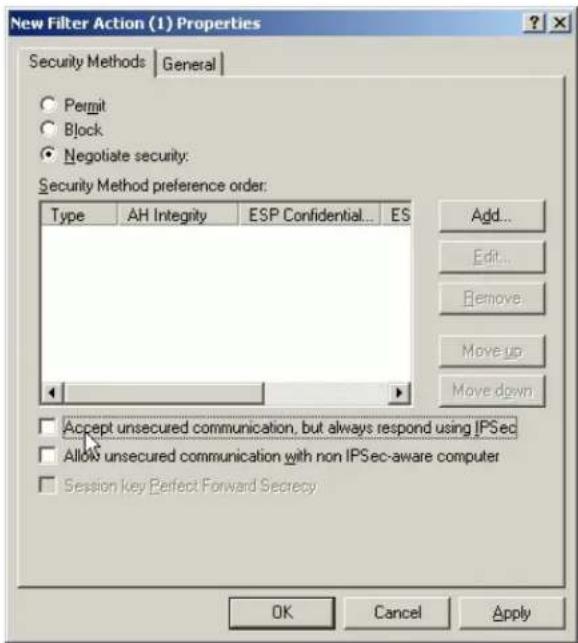
- Click Add and select Custom (for expert users) if you want to define specific algorithms and session key lifetimes). Please make sure the settings match whatever we will configure in P-202H Plus v2 later.
![New Security Method Security Method High (ESP) Data will be encrypted, authentic and unmodified Medium (AH) Data will be authentic and unmodified, but will not be encrypted Custom [for expert users] Settings... OK Cancel Apply](/content/2026/02/353416/images/688c38c090fe43ba35361065290bd40b04f9069991a973eb95a768423e0f713c.jpg)
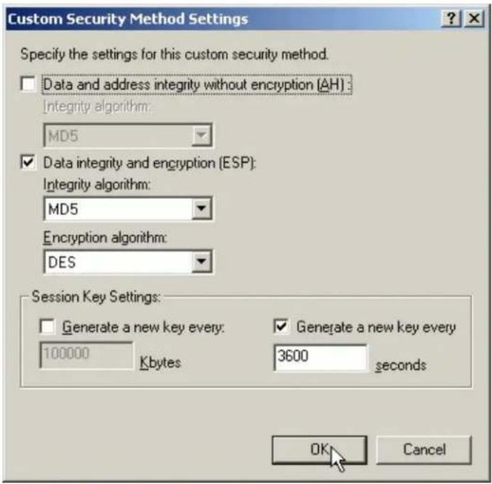
- Click OK. On the General tab, give a name to the filter action. For example, WIN2K to P-202H Plus v2, and click OK.
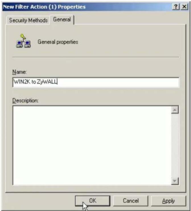
- Select the filter action you just created.
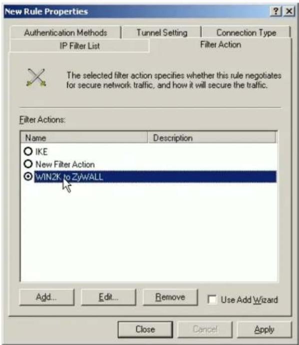
- On the Authentication Methods tab, click Add to select Use this string to protect the key exchange (pre-shared key) option. And enter the string 12345678 in the text box.
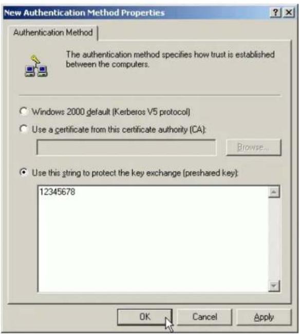
10. Click OK.
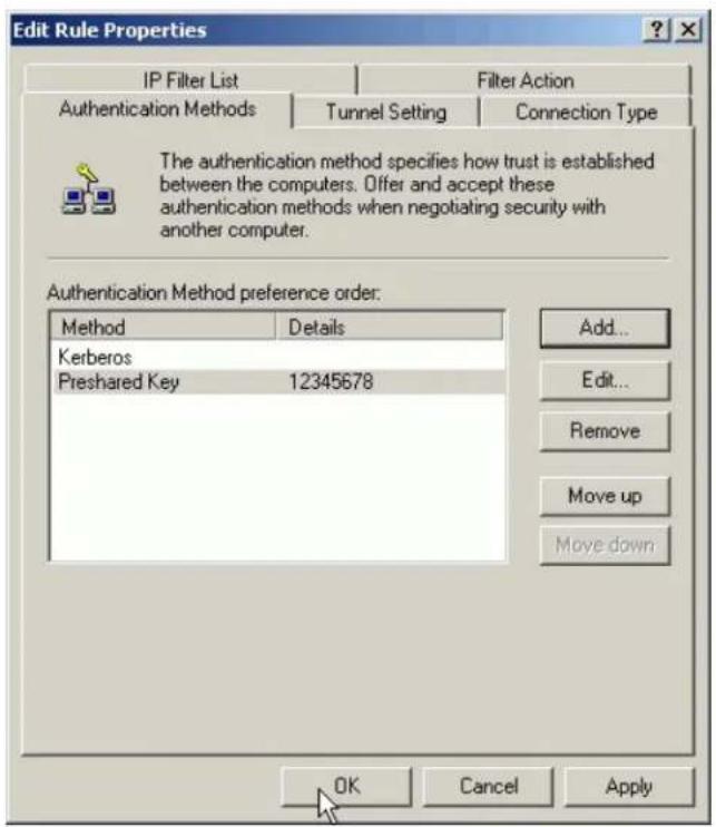
See the finished screen shot.
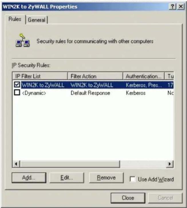
- Configure a Rule for PC 2 to PC 1 tunnel
- In the IPSec policy properties, click Add to create a new rule.
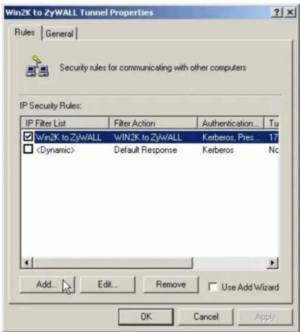
- Select the second filter list you created above from the IP Filter List. For example, P-202H Plus v2 to WIN2K.
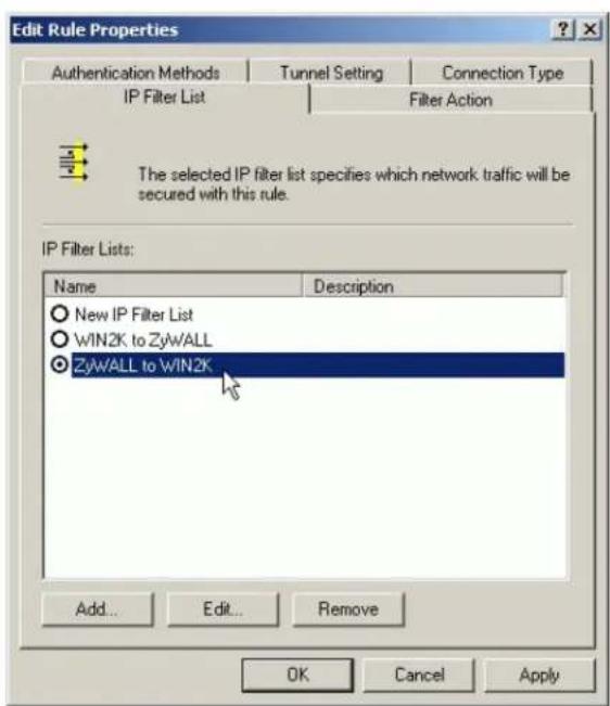
- Click Tunnel Setting tab, enter the remote endpoint. For this filter list, the remote IPSec endpoint is WIN2K.
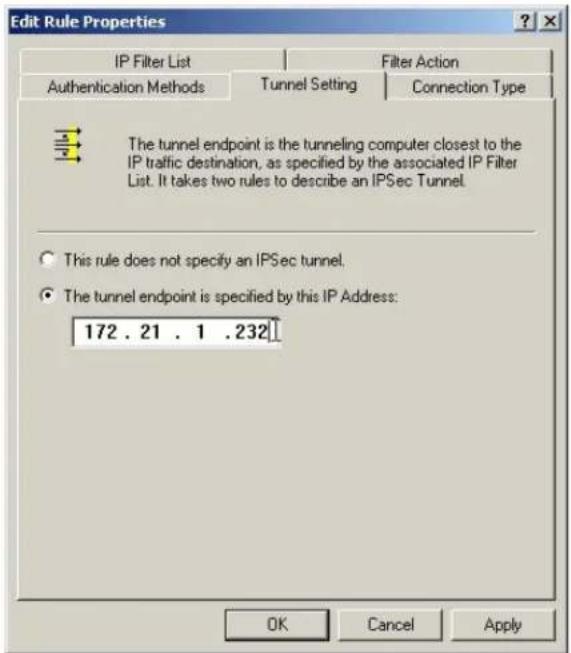
- Click Connection Type tab, click All network connections (or click LAN connections if your WIN2K does not connect to ISP but LAN). In our example, we choose All network connections.
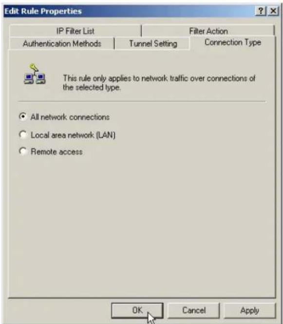
- Click Filter Action tab, select the filter action you created.
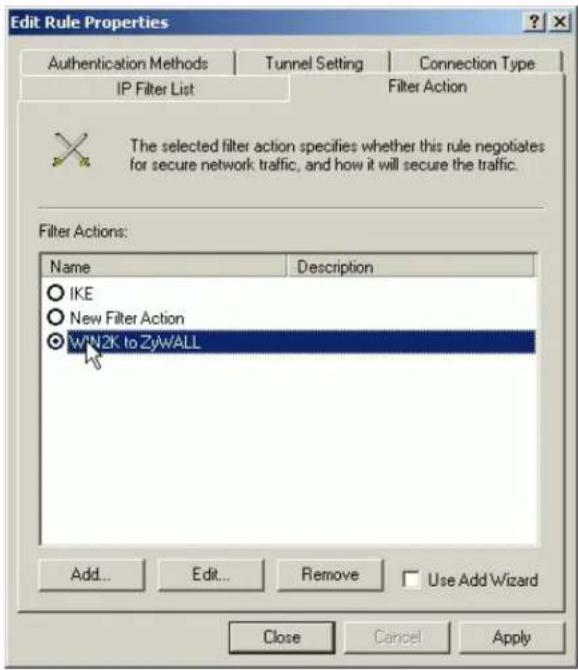
- On the Authentication Method tab, configure the same settings as done in the first rule.

7. Click Close.
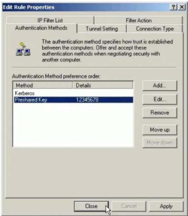
- Enable both rules you created in the policy properties and click Close.
Figure 5: See the finished screen shot
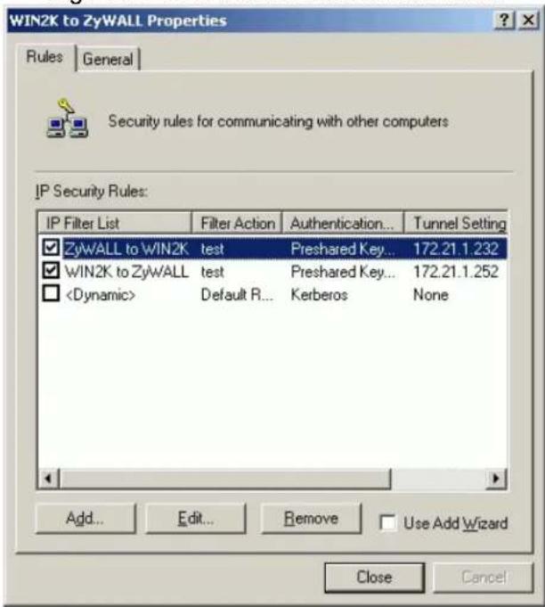
- Assign Your New IPSec Policy to Your Windows 2000
- In the IP Security Policies on Local Machine MMC snap-in, right click your new policy, and click Assign.
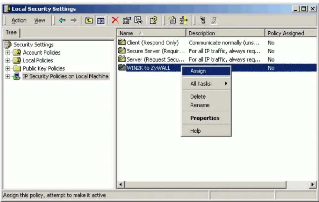
- A green arrow will appear in the folder icon next to your policy. See the screen shot below.
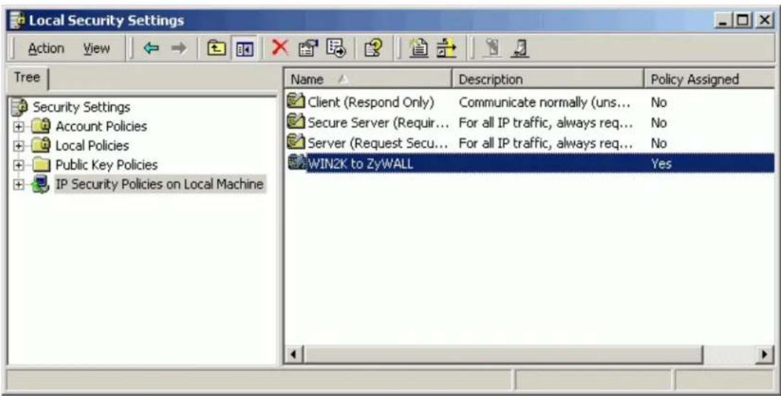
For more information about configure WIN2K IPSec, please refer to the following web site.
1.http://www.microsoft.com/windows2000/techinfo/planning/security/ipsecsteps.asp
2. http://support.microsoft.com/support/kb/articles/q252/7/35.asp
2. Setup P-202H Plus v2 VPN
- Using a web browser, login P-202H Plus v2 by giving the LAN IP address of P-202H Plus v2 in URL field. Default LAN IP is 192.168.1.1, default password to login web configurator is 1234.
- Click Advanced, and click VPN tab on the left.
- On the SUMMARY menu, Select a policy to edit by clicking Edit.
- On the CONFIGURE-IKE menu, check Active check box and give a name to this policy.
- Select IPSec Keying Mode to IKE and Negotiation Mode to Main, as we configured in WIN2K.
- Source IP Address Start and Source IP Address End are PC 2 IP in this example. (the secure host behind P-202H Plus v2)
- Destination IP Address Start and Destination IP Address End are PC 1 in this example. (the secure WIN2K PC) Note: You may assign a range of Source/Destination IP addresses for multiple VPN sessions.
- My IP Addr is the WAN IP of P-202H Plus v2.
- Secure Gateway IP Addr is the remote WIN2K's IP, that is PC 1 in this example.
- Select Encapsulation Mode to Tunnel.
- Check the ESP check box. (AH can not be used in SUA/NAT case)
- Select Encryption Algorithm to DES and Authentication Algorithm to MD5, as we configured in WIN2K.
- Enter the key string 12345678 in the Preshared Key text box, and click Apply.
Figure 8: See the VPN rule screen shot

If you use SMT management, the VPN configurations are as shown below.
Menu 27.1.1 - IPSec Setup
Index #= 1
Name= P-202H Plus v2
Active= Yes
My IP Addr= 172.21.1.252
Secure Gateway IP Addr= 172.21.1.232
Protocol= 0
Local: IP Addr Start= 192.168.1.33 End= 192.168.1.33
Port Start= 0 End= N/A
Remote: IP Addr Start= 172.21.1.232 End= 172.21.1.232
Port Start= 0 End= N/A
Enable Replay Detection= No
Key Management= IKE
Edit IKE Setup= Yes
Edit Manual Setup= N/A
Press ENTER to Confirm or ESC to Cancel:
- Edit IKE settings by selecting 'Edit IKE Setup' option in menu 27.1.1 to 'Yes' and then pressing 'Enter'.
- There are two phases for IKE:
In Phase 1, two IKE peers establish a secure channel for key exchanging.
In Phase 2, two peers negotiate general purpose SAs which are secure channels for data transmission.
Please note that any configuration in 'IKE Setup' should match the settings configured in WIN2K
Negotiation Mode= Main
Pre-Shared Key= 12345678
Encryption Algorithm= DES
Authentication Algorithm= MD5
SA Life Time (Seconds)= 3600
Key Group= DH1
Phase 2
Active Protocol= ESP
Encryption Algorithm= DES
Authentication Algorithm= MD5
SA Life Time (Seconds)= 3600
Encapsulation= Tunnel
Perfect Forward Secrecy (PFS)= None
Press ENTER to Confirm or ESC to Cancel
Soft-PK VPN to P-202H Plus v2 Tunneling
This page guides us to setup a VPN connection between the VPN software and P-202H Plus v2 router. There will be several devices we need to setup for this case. They are VPN software and P-202H Plus v2 router.
As the figure shown below, the tunnel between PC 1 and P-202H Plus v2 ensures the packets flow between them are secure. Because the packets go through the IPSec tunnel are encrypted. To setup this VPN tunnel, the required settings for the software and P-202H Plus v2 are explained in the following sections.
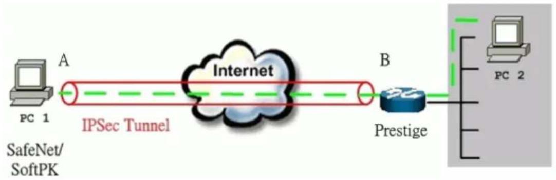
flowchart
graph LR
    A["PC 1<br>SafeNet/SoftPK"] -->|A| B["IPSec Tunnel"]
    B --> C["Internet"]
    C --> D["Prestige"]
    D --> E["PC 2"]
    style A fill:#f9f,stroke:#333
    style B fill:#ccf,stroke:#333
    style C fill:#cff,stroke:#333
    style D fill:#ffc,stroke:#333
    style E fill:#cfc,stroke:#333
The IP addresses we use in this example are as shown below.
| PC 1 | P-202H Plus v2 | PC2 |
| 202.132.155.33 | LAN: 202.132.171.1WAN: 202.132.170.1 | 202.132.171.33 |
1. Setup Soft-PK VPN
- Open Soft-PK Security Policy Editor
- Add a new connection named 'P-202H Plus v2' as shown below.
- Select Connection Security to Secure

Remote Party Identity and Addressing settings:
- In ID Type option, please choose IP Address option, and enter the IP address of the remote PC (PC 2 in this case).
- Check Connect using Secure Gateway Tunnel, please also select IP
Address as ID Type, and enter P-202H Plus v2's WAN
IP address in the following field.
The detailed configuration is shown in the following figure.
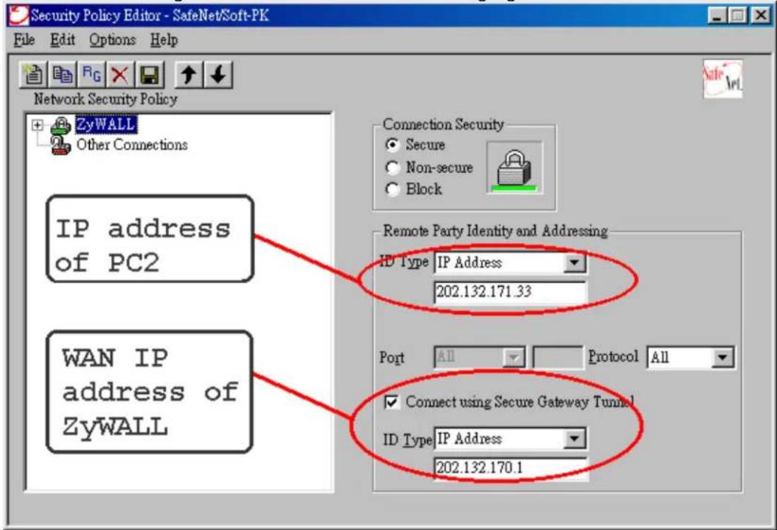
Pre-Share Key Settings:
- Extend P-202H Plus v2 icon, you may see My Identity.
- Click My Identity, click the Pre-Shared Key icon in the right side of the window.
-
Enter a key you that later you will also need to configure in P-202H Plus v2 in the pop out windows. In this example, we enter
-
See below.

Security Policy Settings:
- Click Security Policy option to choose Main Mode as Phase 1 Negotiation Mode
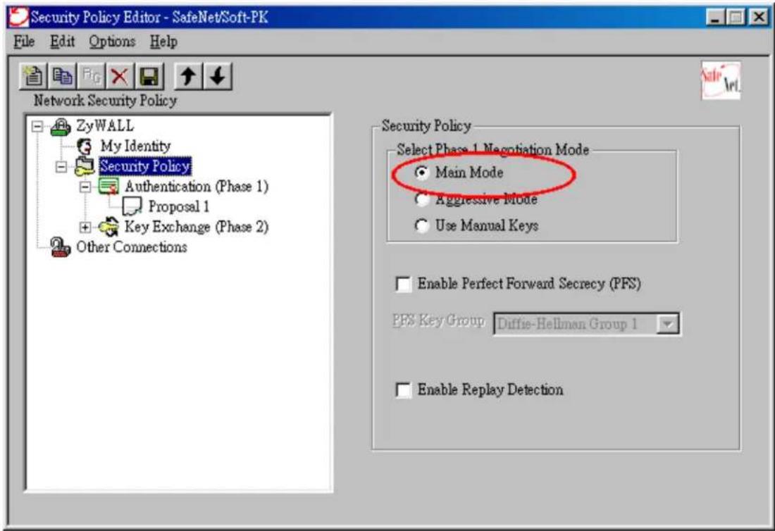
- Extend Security Policy icon, you will see two icons, Authentication (Phase 1) and Key Exchange (Phase 2).
- The settings shown in the following two figures for both Phases are our examples. You can choose any, but they should match whatever you enter in P-202H Plus v2.
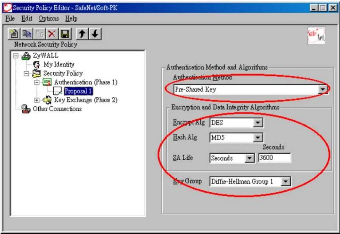
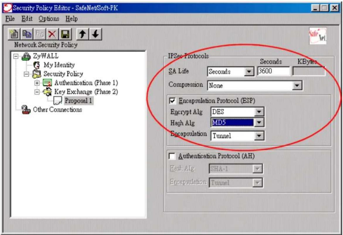
2. Setup P-202H Plus v2 VPN
- Using a web browser, login P-202H Plus v2 by giving the LAN IP address of P-202H Plus v2 in URL field. Default LAN IP is 192.168.1.1, default password to login web configurator is 1234.
- Click Advanced, and click VPN tab on the left.
- On the SUMMARY menu, Select a policy to edit by clicking Edit.
- On the CONFIGURE-IKE menu, check Active check box and give a name to this policy.
- Select IPSec Keying Mode to IKE and Negotiation Mode to Main, as we configured in Soft-PK.
- Source IP Address Start and Source IP Address End are PC 2 IP in this example. (the secure host behind P-202H Plus v2)
- Destination IP Address Start and Destination IP Address End are PC 1 in this example. (the secure remote host) Note: You may assign a range of Source/Destination IP addresses for multiple VPN sessions.
- My IP Addr is the WAN IP of P-202H Plus v2.
- Secure Gateway IP Addr is the remote secure gateway IP, that is PC 1 in this example.
- Select Encapsulation Mode to Tunnel.
- Check the ESP check box. (AH can not be used in SUA/NAT case)
- Select Encryption Algorithm to DES and Authentication Algorithm to SHA1, as we configured in Soft-PK.
- Enter the key string 12345678 in the Preshared Key text box, and click Apply.
Figure 8: See the VPN rule screen shot
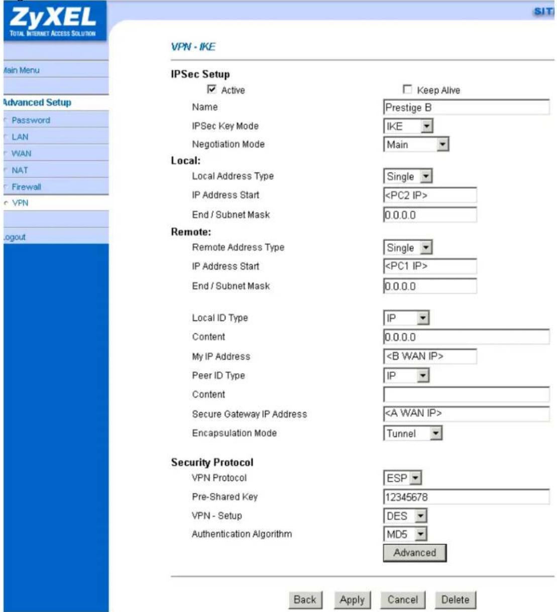
If you use SMT management, the VPN configurations are as shown below.
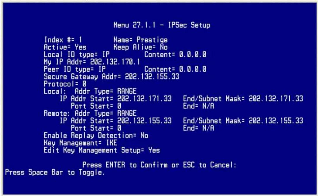
- Edit IKE settings by selecting 'Edit IKE Setup' option in menu27.1.1 to 'Yes' and then pressing 'Enter'.
- There are two phases for IKE:
In Phase 1, two IKE peers establish a secure channel for key exchanging. In Phase 2, two peers negotiate general purpose SAs which are secure channels for data transmission.
Please note that any configuration in 'IKE Setup' should match the settings in VPN software.
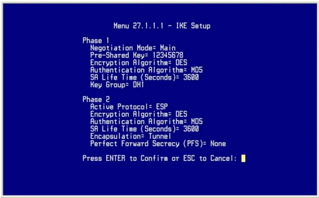
Linux FreeS/WAN VPN to P-202H Plus v2 Tunneling
This page guides us to setup a VPN connection between FreeS/WAN and P-202H Plus v2 router. There will be several devices we need to setup for this case. They are Linux FreeS/WAN and P-202H Plus v2 router.
As the figure shown below, the tunnel between PC 1 and P-202H Plus v2 ensures the packets flow between them are secure. Because the packets go through the IPSec tunnel are encrypted. To setup this VPN tunnel, the required settings for FreeS/WAN and P-202H Plus v2 are explained in the following sections.
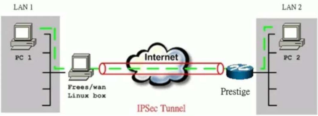
flowchart
graph LR
    subgraph LAN 1
        PC1["PC 1"]
        PC1 --> FreesWan["Frees/wan Linux box"]
    end
    subgraph LAN 2
        PC2["PC 2"]
        PC2 --> Prestige["Prestige"]
    end
    FreesWan --> Internet["Internet"]
    Prestige --> Internet
    IPSec["Tunnel"] --> Internet
The IP addresses we use in this example are as shown below.
| LAN 1 | FreeS/WAN Linux box | P-202H Plus v2 | LAN 2 |
| 192.168.10.0/24 | LAN: 192.168.10.20WAN: 65.170.185.111 Gateway: 65.170.185.65 | LAN:192.168.0.254WAN: 202.132.170.1 Gateway:202.132.170.254 | 192.168.0.0/24 |
1. Setup FreeS/WAN
We presume that your Linux's kernel has been compiled to support FreeS/WAN, and FreeS/WAN has been also installed successfully in your system. You can refer to the following URL for more information, http://www.FreeS/WAN.org/.
Two files must be configured in /etc directory.
ipsec.conf:
config setup
    interfaces="ipsec0=eth1"
    klipsdebug=none
    plutodebug=none
    plutoload=%search
    plutostart=%search
conn %default
    keyingtries=3
conn P-202H Plus v2
    left=65.170.185.111
leftsubnet=192.168.10.0/24
leftnexthop=65.170.185.65
right=202.132.170.1
rightsubnet=192.168.0.0/24
rightnexthop=202.132.170.254
auto=start
pfs=no
authby=secret
ipsec.secrets:
65.170.185.111 202.132.170.1 : PSK "12345678"
2. Setup P-202H Plus v2 VPN
- Using a web browser, login P-202H Plus v2 by giving the LAN IP address of P-202H Plus v2 in URL field. The LAN IP in tihs example is 192.168.0.1, default password to login web configurator is 1234.
- Click Advanced, and click VPN tab on the left.
- On the SUMMARY menu, Select a policy to edit by clicking Edit.
- On the CONFIGURE-IKE menu, check Active check box and give a name to this policy.
- Select IPSec Keying Mode to IKE and Negotiation Mode to Main, Linux FreeS/WAN only supports Main mode.
- In Local section, choose Subnet Address as Address Type. Source IP Address Start is 192.168.0.0 and End is 255.255.255.0 in this example. (the secure network behind P-202H Plus v2)
- In Remote section, choose Subnet Address as Address Type. Source IP Address Start is 192.168.10.0 and End is 255.255.255.0. (the secure network behind Linux)
- My IP Addr is the WAN IP of P-202H Plus v2.
- Secure Gateway IP Addr is the remote secure gateway IP, that is Linx box in this example.
- Select Encapsulation Mode to Tunnel.
- Check the ESP check box. (AH can not be used in SUA/NAT case)
- Select Encryption Algorithm to 3DES and Authentication Algorithm to SHA1.
- Enter the key string 12345678 in the Preshared Key text box, and click Apply.

You can click Advanced button to check IPSec Phase 1 and Phase 2 parameters. Please note that Linux FreeS/WAN only supports 3DES as encryption algorithm, and DH2 or upper as key exchange group.

VPN·IKE·Advanced Setup
VPN - IKE
Protocol
Enable Replay Detection
Local Start Port
Remote Start Port
Phase1
Negotiation Mode
Pre-Shared Key
Encryption Algorithm
Authentication Algorithm
SA Life Time (Seconds)
Key Group
Phase2
Active Protocol
Encryption Algorithm
Authentication Algorithm
SA Life Time (Seconds)
Encapsulation
Perfect Forward Secrecy(PFS)
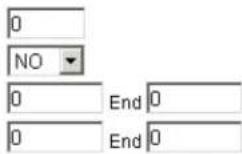
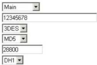
If you use SMT management, the VPN configurations are as shown below.
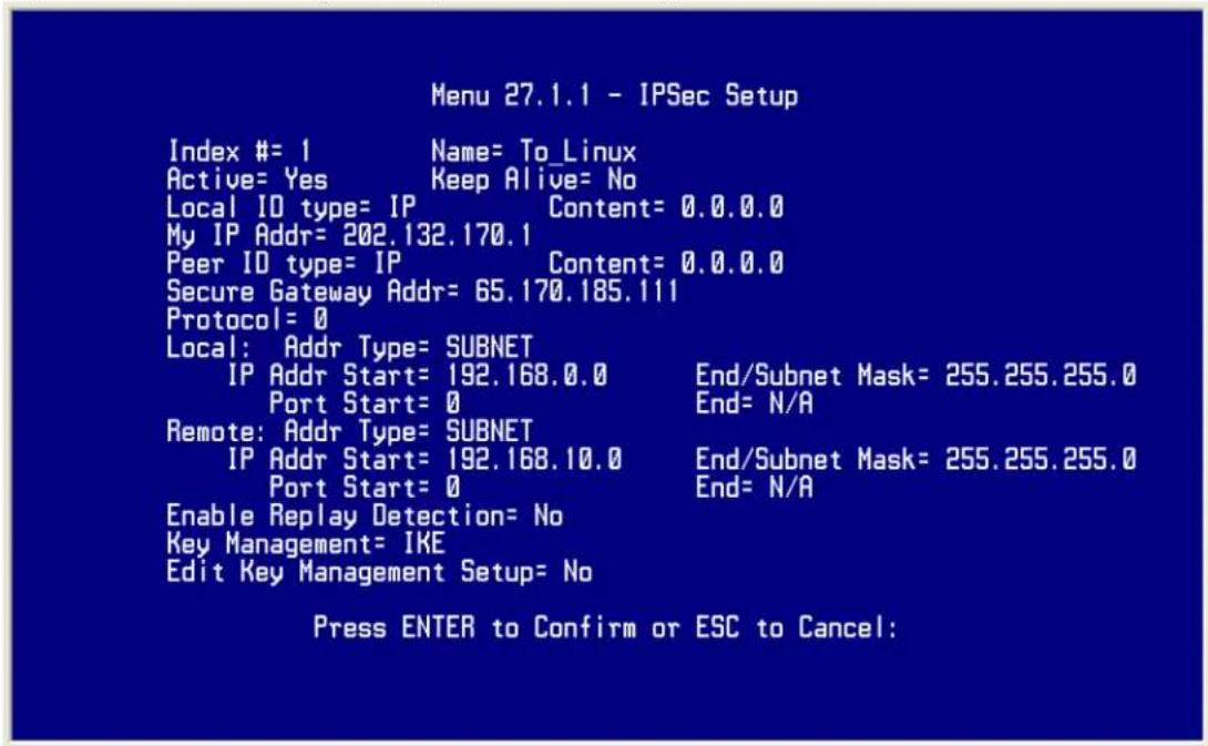
- Edit IKE settings by selecting 'Edit Key Management Setup' option in menu27.1.1 to 'Yes' by pressing space bar and then pressing 'Enter'.
- There are two phases for IKE:
In Phase 1, two IKE peers establish a secure channel for key exchanging. In Phase 2, two peers negotiate IPSec SAs which are used for data transmission.
Please note that Linux FreeS/WAN only supports 3DES as encryption algorithm, and DH2 or upper as key exchange group.

SSH Sentinel to P-202H Plus v2 Tunneling
Sentinel (Static IP) to P-202H Plus v2(Static IP) Tunneling
This page guides us to setup a VPN connection between the Sentinel software and P-202H Plus v2 router. There will be several devices we need to setup for this case. They are Sentinel software and P-202H Plus v2 router.
As the figure shown below, the tunnel between PC 1, with Sentinel installed, and P-202H Plus v2 ensures the packets flow between them are secure. Because the packets go through the IPSec tunnel are encrypted. To setup this VPN tunnel, the required settings for Sentinel and P-202H Plus v2 are explained in the following sections. As the red pipe shown in the following figure, the tunneling endpoints are Sentinel and P-202H Plus v2.
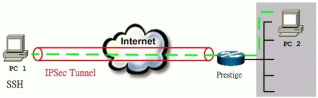
flowchart
graph LR
    A["PC 1 SSH"] --> B["IPSec Tunnel"]
    B --> C["Internet"]
    C --> D["Prestige"]
    D --> E["PC 2"]
The IP addresses we use in this example are as shown below.
| PC 1 | P-202H Plus v2 | PC2 |
| 172.21.1.232 | LAN: 192.168.1.1WAN: 172.21.1.252 | 192.168.1.33 |
1. Setup Sentinel
- From Tool Tray of Windows system, right click on your SSH/Sentinel icon, and then choose Run Policy Editor.

- Choose Key Management. Select My Keys, then press Add... button.

- Select Create a preshared key, and press Next.
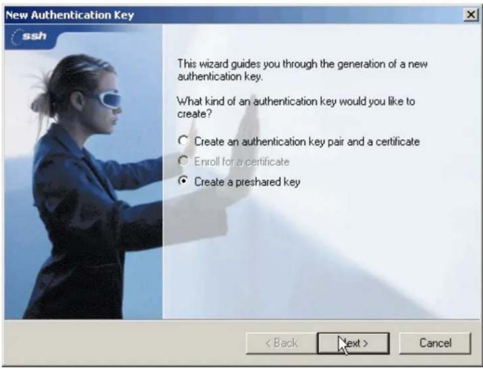
- Give this preshared key a name, P-202H Plus v2. And then enter the preshared key "12345678" in both Shared secret and Confirm shared secret fields. Finally press Finish.

- Press Apply in Main menu to save the above settings for latter use.

- Switch to Security Policy tab. Choose VPN connections, and then press Add...

- Add VPN Connection window will pop out. Press IP button besides Gateway Name box. Enter P-202H Plus v210's WAN IP address in Gateway IP address.

- Press ... button besides Remote network.
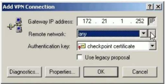
- Network Editor Window will pop out. Press New button, and Enter P-202H Plus v2 in Network name, and 192.168.1.0 in IP address field, and 255.255.255.0 in Subnet Mask field. Then click OK to go back to Add VPN Connection window.
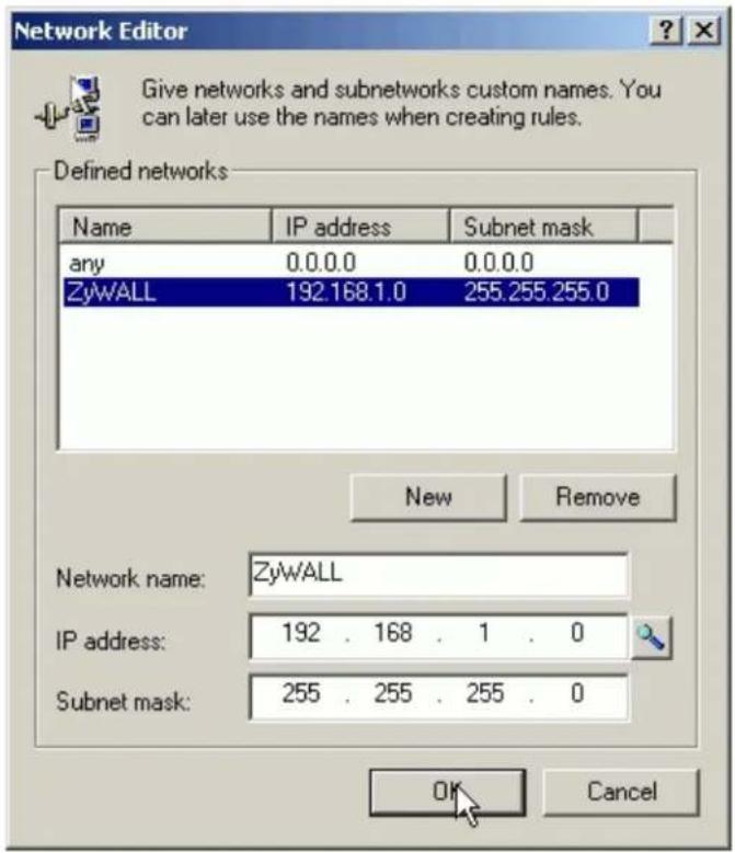
- Choose P-202H Plus v2 as Authentication Key. Then click OK to save.

- In SSH Sentinel Policy Editor, you will get a new VPN connection, 172.21.1.252(P-202H Plus v2), choose this item, and then press Properties... button.
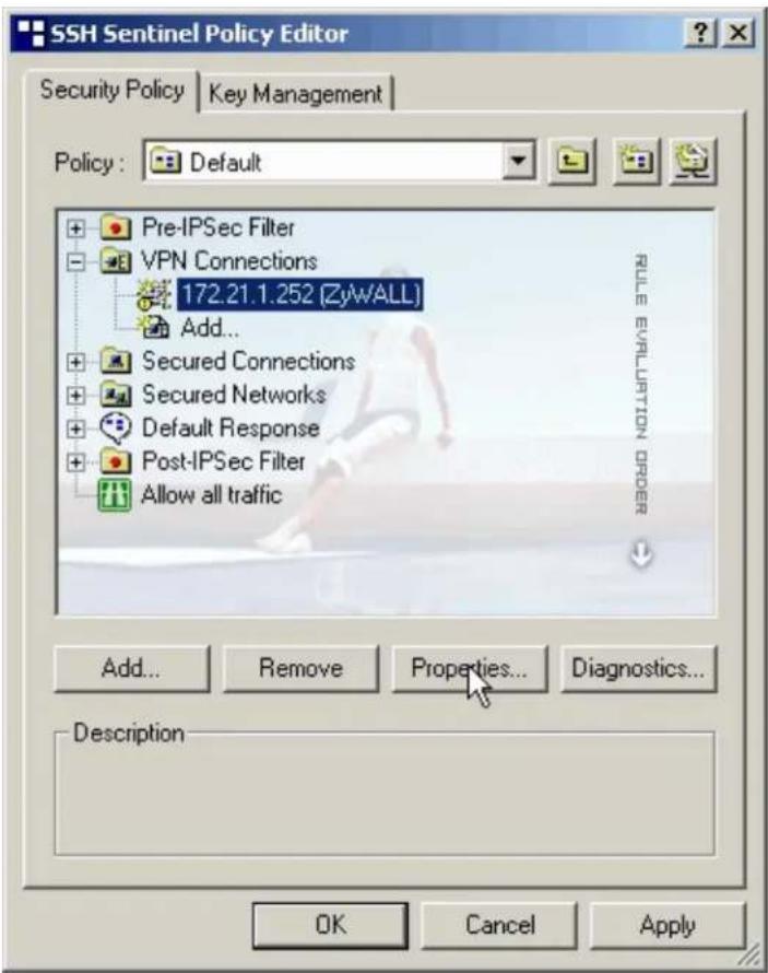
- Choose Settings button in Remote endpoint section. Please uncheck the boxes of "Acquire virtual IP address" and "Extended authentication".
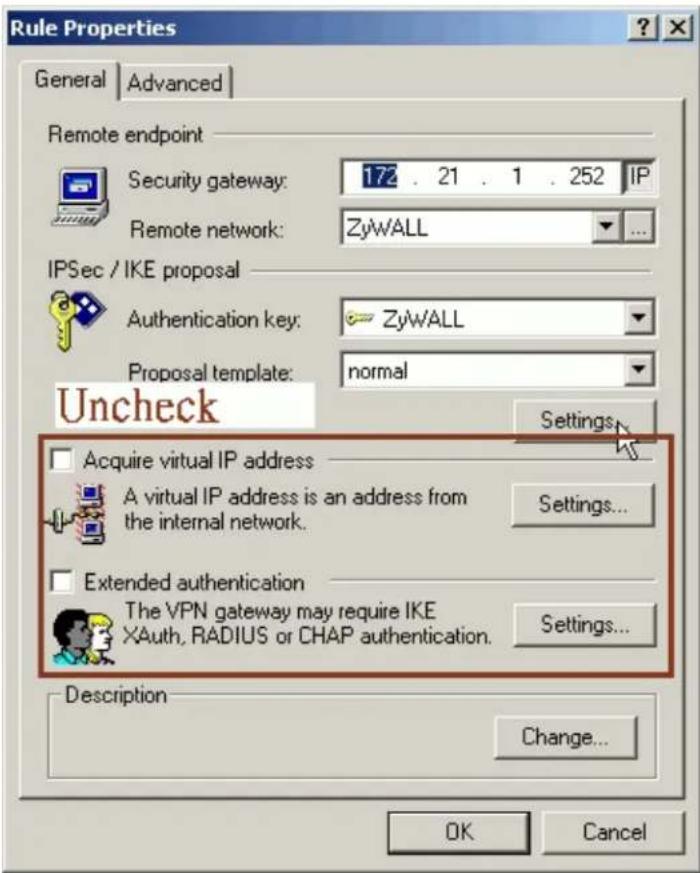
- Tune IKE proposal to Encryption algorithm as DES, Integrity function as MD5, IKE mode as main mode, IKE group as MODP 768 (group 1), and IPSec proposal to Encryption algorithm as DES, Integrity function as HMAC-MD5, PFS group as none.

- Press Apply to save all of the settings.
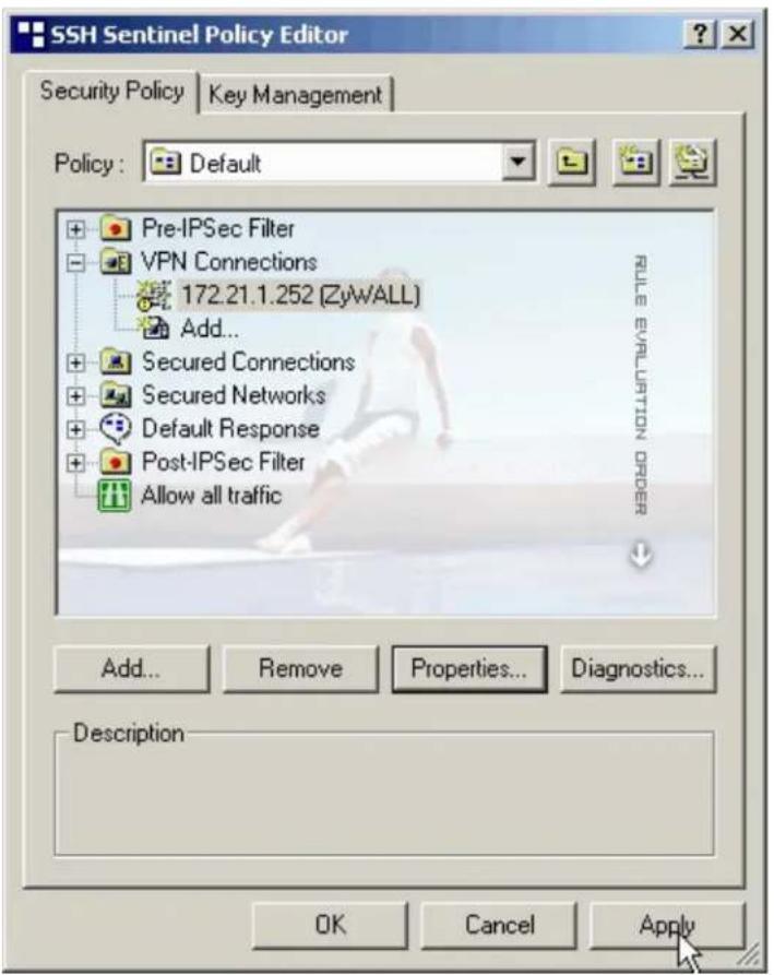
- Initiate VPN connection from Sentinel by selecting your VPN connection from Select VPN item.
Note:
A. When building VPN between Sentinel and P-202H Plus v2, the tunnel can't be initiated from P-202H Plus v2 side. Please always initiate the tunnel from Sentinel.
B. VPN tunnel on Sentinel can't be initiated by triggered packets (such as ping, ftp, telnet, HTTP...etc.) You can only initiate VPN tunnel by choosing "Select VPN" from SSH/Sentinel tray.

NOTE:
Please check your P-202H Plus v2's release note, if your current firmware version doesn't support Mega Bytes as SA lifetime. You have to Zero your Mega Bytes setting in SA life time. Switch to Security Policy, the configuration page is in
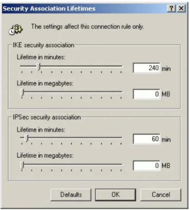
2. Setup P-202H Plus v2 VPN
- Using a web browser, login P-202H Plus v2 by giving the LAN IP address of P-202H Plus v2 in URL field. Default LAN IP is 192.168.1.1, default password to login web configurator is 1234.
- Go to Advanced -> VPN
- Check Active box to enable this rule. Check Keep alive to make your VPN connection stay permanent.
- Select Negotiation Mode to Main, as we configured in Sentinel.
- Local IP, Address Type is Subnet, Address Start is 192.168.1.0, End/Subnet Mask is 255.255.255.0.
- Remote IP, Address Type is Single, Address Start is Sentinel's IP, 172.21.1.232
- My IP Addr is the WAN IP of P-202H Plus v2.
- Secure Gateway IP Addr is also Sentinel's IP, 172.21.1.232
- Select Encapsulation Mode to Tunnel.
- Check the ESP check box. (AH can not be used in SUA/NAT case)
- Select Encryption Algorithm to DES and Authentication Algorithm to MD5, as we configured in Sentinel.
- Enter the key string 12345678 in the Preshared Key text box, and click Apply.
- Press Advanced button to set IKE phase 1 and phase 2 parameters.
See the VPN rule screen shot
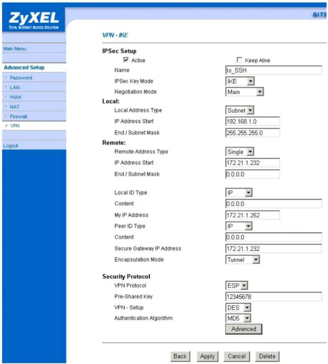
Set IKE Phase 1 and Phase 2 parameters.

SIT
VPN·IKE·Advanced Setup
VPN - IKE
Protocol
Enable Replay Detection
Local Start Port
Remote Start Port

Phase1
Negotiation Mode
Pre-Shared Key
Encryption Algorithm
Authentication Algorithm
SA Life Time (Seconds)
Key Group
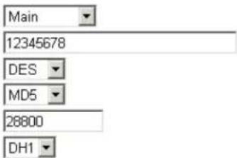
Encryption Algorithm
Authentication Algorithm
SA Life Time (Seconds)
Encapsulation
Perfect Forward Secrecy(PFS)
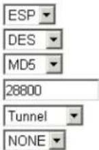
Apply Cancel
If you use SMT management, the VPN configurations are as shown below.
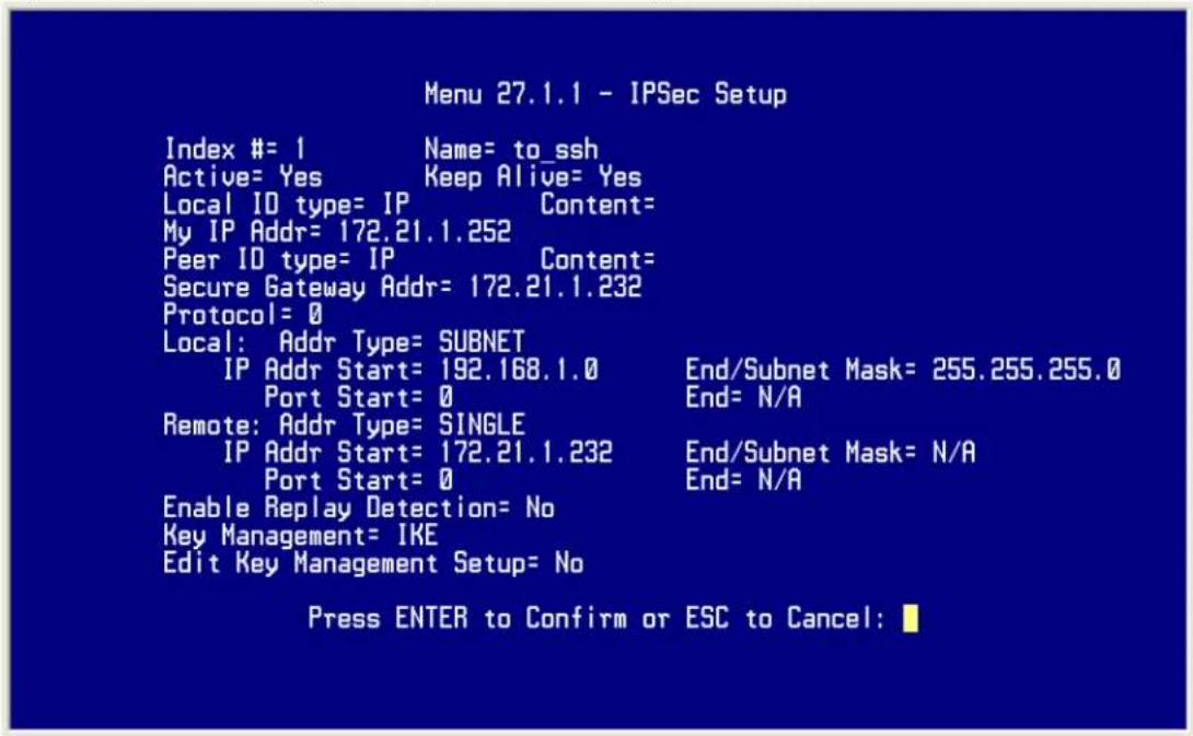
- Edit IKE settings by selecting 'Edit IKE Setup' option in menu 27.1.1 to 'Yes' and then pressing 'Enter'.
- There are two phases for IKE:
In Phase 1, two IKE peers establish a secure channel for key exchanging.
In Phase 2, two peers negotiate general purpose SAs which are secure channels for data transmission.
Please note that any configuration in 'IKE Setup' should match the settings configured in Sentinel
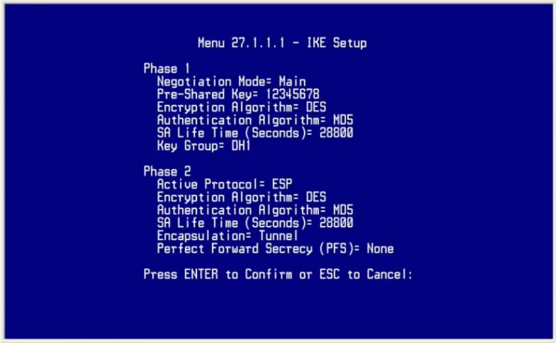
Sentinel (Dynamic IP) to P-202H Plus v2(Static IP) Tunneling
This page guides us to setup a VPN connection between the Sentinel software and P-202H Plus v2 router. There will be several devices we need to setup for this case. They are Sentinel software and P-202H Plus v2 router.
As the figure shown below, the tunnel between PC 1, with Sentinel installed, and P-202H Plus v2 ensures the packets flow between them are secure. Because the packets go through the IPSec tunnel are encrypted. To setup this VPN tunnel, the required settings for Sentinel and P-202H Plus v2 are explained in the following sections. As the red pipe shown in the following figure, the tunneling endpoints are Sentinel and P-202H Plus v2.

flowchart
graph LR
    A["PC 1 SSH"] --> B["IPSec Tunnel"]
    B --> C["Internet"]
    C --> D["Prestige"]
    D --> E["PC 2"]
The IP addresses we use in this example are as shown below.
| PC 1 | P-202H Plus v2 | PC2 |
| LAN: 192.168.1.1WAN: 172.21.1.252 | 192.168.1.33 |
1. Setup Sentinel
- From Tool Tray of Windows system, right click on your Sentinel icon, and then choose Run Policy Editor.
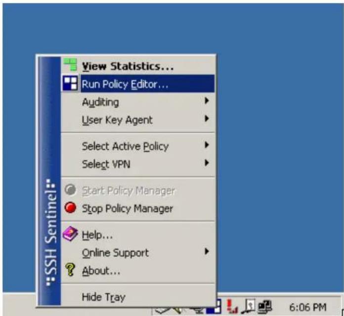
- Choose Key Management. Select My Keys, then press Add... button.

- Select Create a preshared key, and press Next.

- Give this preshared key a name, P-202H Plus v2. And then enter the preshared key "12345678" in both Shared secret and Confirm shared secret fields. Finally press Finish.
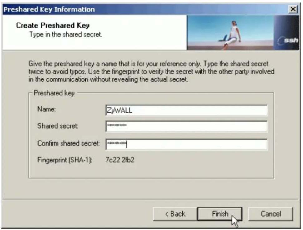
- Press Apply in Main menu to save the above settings for latter use.
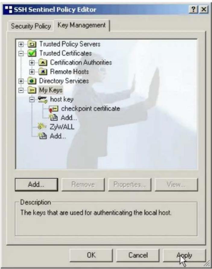
- Switch to Security Policy tab. Choose VPN connections, and then press Add...
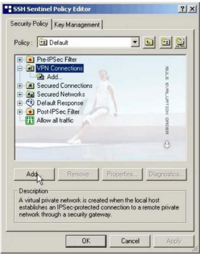
- Add VPN Connection window will pop out. Press IP button besides Gateway Name box. Enter P-202H Plus v210's WAN IP address in Gateway IP address.

- Press ... button besides Remote network.

- Network Editor Window will pop out. Press New button, and Enter P-202H Plus v2 in Network name, and 192.168.1.0 in IP address field, and 255.255.255.0 in Subnet Mask field. Then click OK to go back to Add VPN Connection window.

- Choose P-202H Plus v2 as Authentication Key. Then click OK to save.

- In SSH Sentinel Policy Editor, you will get a new VPN connection, 172.21.1.252(P-202H Plus v2), choose this item, and then press Properties... button.

- Choose Settings button in Remote endpoint section. Please uncheck the boxes of "Acquire virtual IP address" and "Extended authentication".

- Tune IKE proposal to Encryption algorithm as DES, Integrity function as MD5, IKE mode as main mode, IKE group as MODP 768 (group 1), and IPSec proposal to Encryption algorithm as DES, Integrity function as HMAC-MD5, PFS group as none.

- Press Apply to save all of the settings.
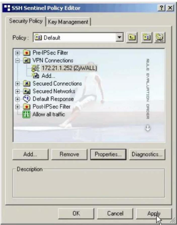
- Initiate VPN connection from Sentinel by selecting your VPN connection from Select VPN item.
Note:
A. When building VPN between Sentinel and P-202H Plus v2, the tunnel can't be initiated from P-202H Plus v2 side. Please always initiate the tunnel from Sentinel.
B. VPN tunnel on Sentinel can't be initiated by triggered packets (such as ping, ftp, telnet, HTTP...etc.) You can only initiate VPN tunnel by choosing "Select VPN" from SSH/Sentinel tray.

NOTE:
Please check your P-202H Plus v2's release note, if your current firmware version doesn't support Mega Bytes as SA lifetime. You have to Zero your Mega Bytes setting in SA life time. Switch to Security Policy, the configuration page is in

2. Setup P-202H Plus v2 VPN
- Using a web browser, login P-202H Plus v2 by giving the LAN IP address of P-202H Plus v2 in URL field. Default LAN IP is 192.168.1.1, default password to login web configurator is 1234.
- Go to Advanced -> VPN
- Check Active box to enable this rule. Check Keep alive to make your VPN connection stay permanent.
- Select Negotiation Mode to Main, as we configured in Sentinel.
- Local IP, Address Type is Subnet, Address Start is 192.168.1.0, End/Subnet Mask is 255.255.255.0.
- Remote IP, leave it as default setup. 0.0.0.0/0.0.0.0
- My IP Addr is the WAN IP of P-202H Plus v2.
- Secure Gateway IP Addr is 0.0.0.0.
- Select Encapsulation Mode to Tunnel.
- Check the ESP check box. (AH can not be used in SUA/NAT case)
- Select Encryption Algorithm to DES and Authentication Algorithm to MD5, as we configured in Sentinel.
- Enter the key string 12345678 in the Preshared Key text box, and click Apply.
- Press Advanced button to set IKE phase 1 and phase 2 parameters.
See the VPN rule screen shot

Set IKE Phase 1 and Phase 2 parameters.

VPN·IKE·Advanced Setup
VPN - IKE
Protocol
Enable Replay Detection
Local Start Port
Remote Start Port

Phase1
Negotiation Mode
Pre-Shared Key
Encryption Algorithm
Authentication Algorithm
SA Life Time (Seconds)
Key Group

Encryption Algorithm
Authentication Algorithm
SA Life Time (Seconds)
Encapsulation
Perfect Forward Secrecy(PFS)

Apply Cancel
If you use SMT management, the VPN configurations are as shown below.
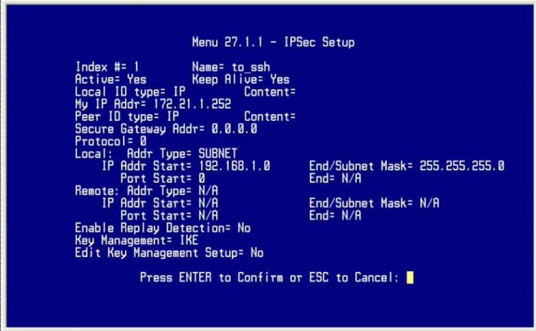
- Edit IKE settings by selecting 'Edit IKE Setup' option in menu 27.1.1 to 'Yes' and then pressing 'Enter'.
- There are two phases for IKE:
In Phase 1, two IKE peers establish a secure channel for key exchanging.
In Phase 2, two peers negotiate general purpose SAs which are secure channels for data transmission.
Please note that any configuration in 'IKE Setup' should match the settings configured in Sentinel
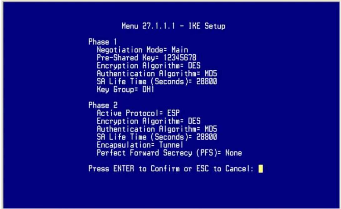
Sentinel (Behind NAT) to P-202H Plus v2(Static IP) Tunneling
This page guides us to setup a VPN connection between the Sentinel software and P-202H Plus v2 router. There will be several devices we need to setup for this case. They are Sentinel software and P-202H Plus v2 router.
As the figure shown below, the tunnel between PC 1, with Sentinel installed, and P-202H Plus v2 ensures the packets flow between them are secure. Because the packets go through the IPSec tunnel are encrypted. To setup this VPN tunnel, the required settings for Sentinel and P-202H Plus v2 are explained in the following sections. As the red pipe shown in the following figure, the tunneling endpoints are Sentinel and P-202H Plus v2.
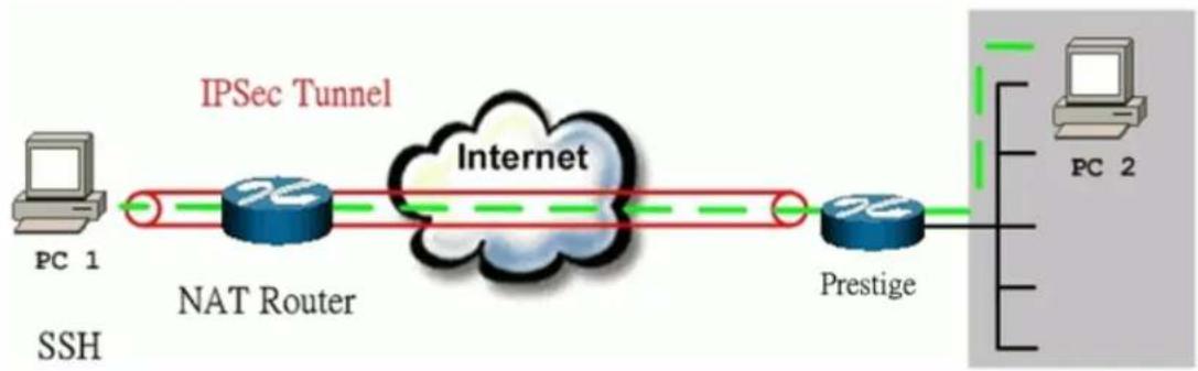
flowchart
graph LR
    PC1["PC 1"] -->|IPSec Tunnel| Internet["Internet"]
    Internet -->|NAT Router| NATRouter["NAT Router"]
    Internet --> Prestige["Prestige"]
    Prestige --> PC2["PC 2"]
The IP addresses we use in this example are as shown below.
| PC 1 | NAT Router | P-202H Plus v2 | PC2 |
| 192.168.2.33 | LAN:192.168.2.1WAN:172.21.1.232 | LAN: 192.168.1.1WAN: 172.21.1.252 | 192.168.1.33 |
1. Setup SSH Sentinel
- From Tool Tray of Windows system, right click on your SSH/Sentinel icon, and then choose Run Policy Editor.
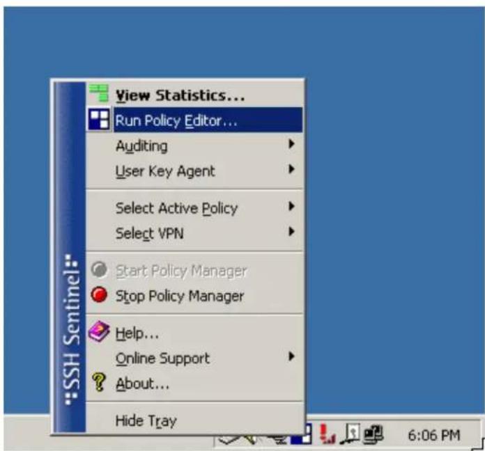
- Choose Key Management. Select My Keys, then press Add... button.
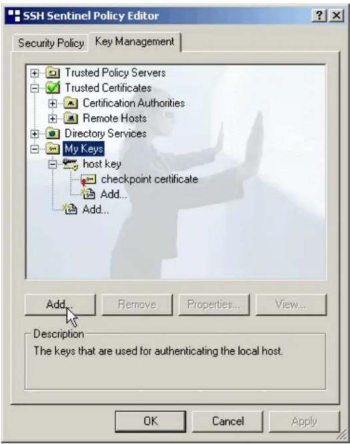
- Select Create a preshared key, and press Next.

- Give this preshared key a name, P-202H Plus v2. And then enter the preshared key "12345678" in both Shared secret and Confirm shared secret fields. Finally press Finish.

- Press Apply in Main menu to save the above settings for latter use.

- Switch to Security Policy tab. Choose VPN connections, and then press Add...

- Add VPN Connection window will pop out. Press IP button besides Gateway Name box. Enter P-202H Plus v210's WAN IP address in Gateway IP address.
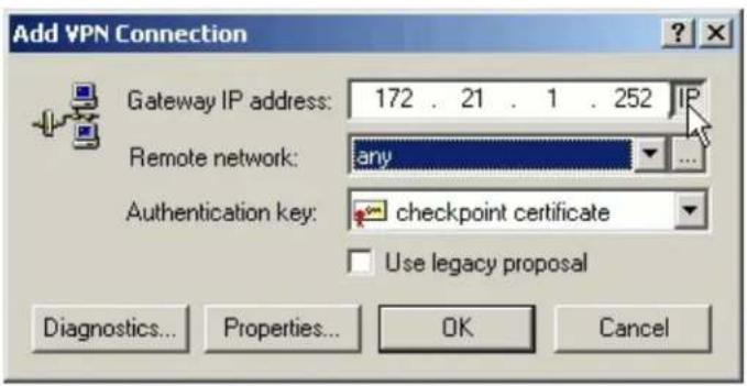
- Press ... button besides Remote network.

- Network Editor Window will pop out. Press New button, and Enter P-202H Plus v2 in Network name, and 192.168.1.0 in IP address field, and 255.255.255.0 in Subnet Mask field. Then click OK to go back to Add VPN Connection window.

- Choose P-202H Plus v2 as Authentication Key. Then click OK to save.
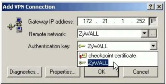
- In SSH Sentinel Policy Editor, you will get a new VPN connection, 172.21.1.252(P-202H Plus v2), choose this item, and then press Properties... button.

- Choose Settings button in Remote endpoint section. Please uncheck the boxes of "Acquire virtual IP address" and "Extended authentication".

- Tune IKE proposal to Encryption algorithm as DES, Integrity function as MD5, IKE mode as main mode, IKE group as MODP 768 (group 1), and IPSec proposal to Encryption algorithm as DES, Integrity function as HMAC-MD5, PFS group as none.
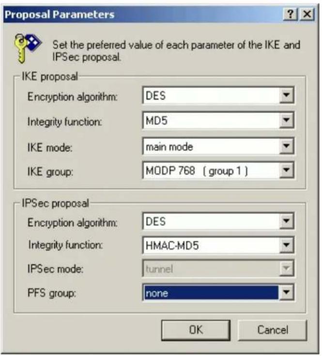
- Press Apply to save all of the settings.
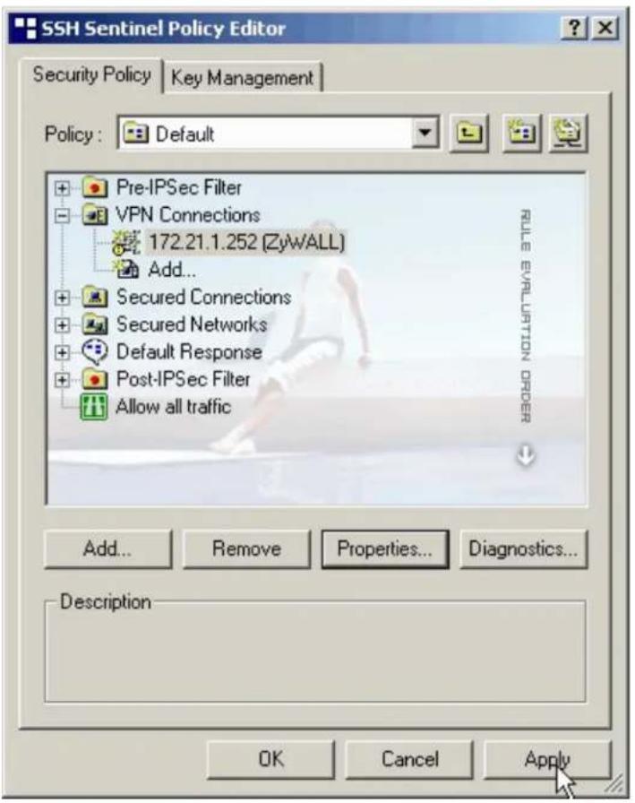
- Initiate VPN connection from Sentinel by selecting your VPN connection from Select VPN item.
Note:
A. When building VPN between Sentinel and P-202H Plus v2, the tunnel can't be initiated from P-202H Plus v2 side. Please always initiate the tunnel from Sentinel.
B. VPN tunnel on Sentinel can't be initiated by triggered packets (such as ping, ftp, telnet, HTTP...etc.) You can only initiate VPN tunnel by choosing "Select VPN" from SSH/Sentinel tray.
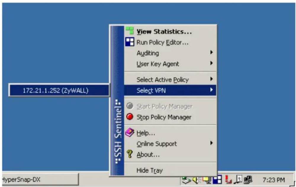
NOTE:
Please check your P-202H Plus v2's release note, if your current firmware version doesn't support Mega Bytes as SA lifetime. You have to Zero your Mega Bytes setting in SA life time. Switch to Security Policy, the configuration page is in

2. Setup P-202H Plus v2 VPN
- Using a web browser, login P-202H Plus v2 by giving the LAN IP address of P-202H Plus v2 in URL field. Default LAN IP is 192.168.1.1, default password to login web configurator is 1234.
- Go to Advanced -> VPN
- Check Active box to enable this rule. Check Keep alive to make your VPN connection stay permanent.
- Select Negotiation Mode to Main, as we configured in Sentinel.
- Local IP, Address Type is Subnet, Address Start is 192.168.1.0, End/Subnet Mask is 255.255.255.0.
- Remote IP Address Start is Sentinel's IP, 192.168.2.33.
- My IP Addr is the WAN IP of P-202H Plus v2.
- Secure Gateway IP Addr is the NAT Router's IP.
- Select Encapsulation Mode to Tunnel.
- Check the ESP check box. (AH can not be used in SUA/NAT case)
- Select Encryption Algorithm to DES and Authentication Algorithm to MD5, as we configured in Sentinel.
- Enter the key string 12345678 in the Preshared Key text box, and click Apply.
- Press Advanced button to set IKE phase 1 and phase 2 parameters.
See the VPN rule screen shot
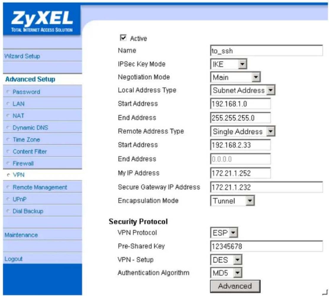
Set IKE Phase 1 and Phase 2 parameters.

VPN·IKE·Advanced Setup
VPN - IKE
Protocol
Enable Replay Detection
Local Start Port
Remote Start Port

Phase1
Negotiation Mode
Pre-Shared Key
Encryption Algorithm
Authentication Algorithm
SA Life Time (Seconds)
Key Group
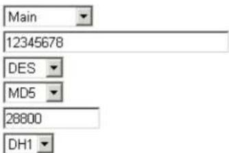
Encryption Algorithm
Authentication Algorithm
SA Life Time (Seconds)
Encapsulation
Perfect Forward Secrecy(PFS)
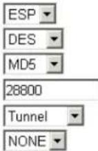
Apply Cancel
If you use SMT management, the VPN configurations are as shown below.
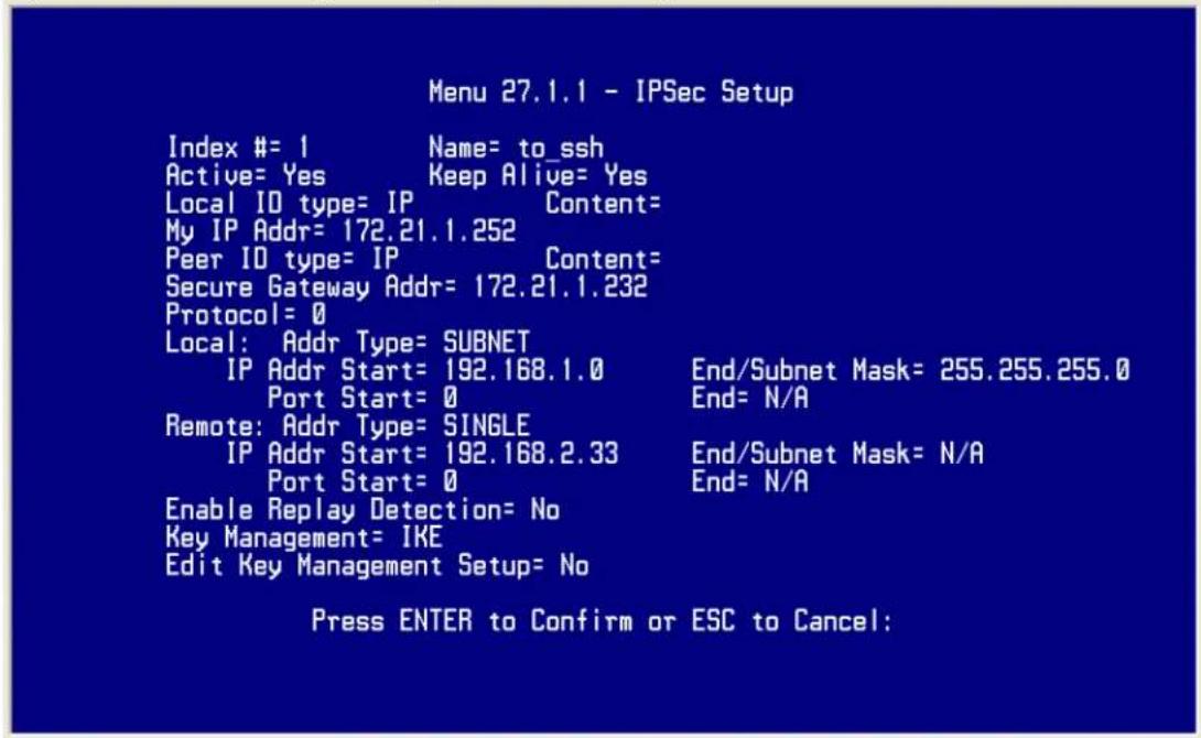
- Edit IKE settings by selecting 'Edit IKE Setup' option in menu 27.1.1 to 'Yes' and then pressing 'Enter'.
- There are two phases for IKE:
In Phase 1, two IKE peers establish a secure channel for key exchanging.
In Phase 2, two peers negotiate general purpose SAs which are secure channels for data transmission.
Please note that any configuration in 'IKE Setup' should match the settings configured in Sentinel

3. Setup in NAT Router
In this case, since VPN connection can only be initiated from SSH Sentinel, no NAT port forwarding is needed.
Sentinel (Dynamic IP) to P-202H Plus v2(Dynamic IP) Tunneling
This page guides us to setup a VPN connection between the SSH Sentinel software and P-202H Plus v2 router. There will be several devices we need to setup for this case. They are Sentinel and P-202H Plus v2 router.
As the figure shown below, the tunnel between PC 1, with Sentinel installed, and P-202H Plus v2 ensures the packets flow between them are secure. Because the packets go through the IPSec tunnel are encrypted. To setup this VPN tunnel, the required settings for Sentinel and P-202H Plus v2 are explained in the following sections. As the red pipe shown in the following figure, the tunneling endpoints are Sentinel and P-202H Plus v2.

flowchart
graph LR
    A["PC 1"] --> B["IPSec Tunnel"]
    B --> C["Internet"]
    C --> D["Prestige"]
    D --> E["PC 2"]
The IP addresses we use in this example are as shown below.
| PC 1 | P-202H Plus v2 | PC2 |
| LAN: 192.168.1.1WAN: | 192.168.1.33 |
1. Setup P-202H Plus v2
- Configure P-202H Plus v2 to use DDNS for WAN IP address update. You can refer to Using DDNS for how to configure it. We presume that you have got a dynamic domain name, P-202H Plus v2.ddns.org, and update your current WAN IP successfully.
- Using a web browser, login P-202H Plus v2 by giving the LAN IP address of P-202H Plus v2 in URL field. Default LAN IP is 192.168.1.1, default password to login web configurator is 1234.
- Go to Advanced -> VPN
- Check Active box to enable this rule. Check Keep alive to make your VPN connection stay permanent.
- Select Negotiation Mode to Main..
- Local IP, Address Type is Subnet, Address Start is 192.168.1.0, End/Subnet Mask is 255.255.255.0.
- Remote IP, leave this field as blank.
- My IP Addr, leave this field as 0.0.0.0.
- Secure Gateway IP Addr is Sentinel's IP, since Sentinel is using dynamic IP address, fill this field as 0.0.0.0.
- Select Encapsulation Mode to Tunnel.
- Check the ESP check box. (AH can not be used in SUA/NAT case)
- Select Encryption Algorithm to DES and Authentication Algorithm to MD5..
- Enter the key string 12345678 in the Preshared Key text box, and click Apply.
- Press Advanced button to set IKE phase 1 and phase 2 parameters.
See the VPN rule screen shot
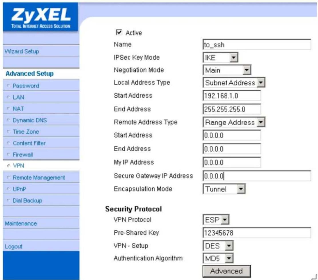
Set IKE Phase 1 and Phase 2 parameters.

VPN·IKE·Advanced Setup
VPN - IKE
Protocol
Enable Replay Detection
Local Start Port
Remote Start Port
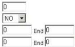
Phase1
Negotiation Mode
Pre-Shared Key
Encryption Algorithm
Authentication Algorithm
SA Life Time (Seconds)
Key Group
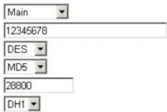
Encryption Algorithm
Authentication Algorithm
SA Life Time (Seconds)
Encapsulation
Perfect Forward Secrecy(PFS)
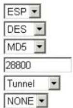
Apply Cancel
If you use SMT management, the VPN configurations are as shown below.
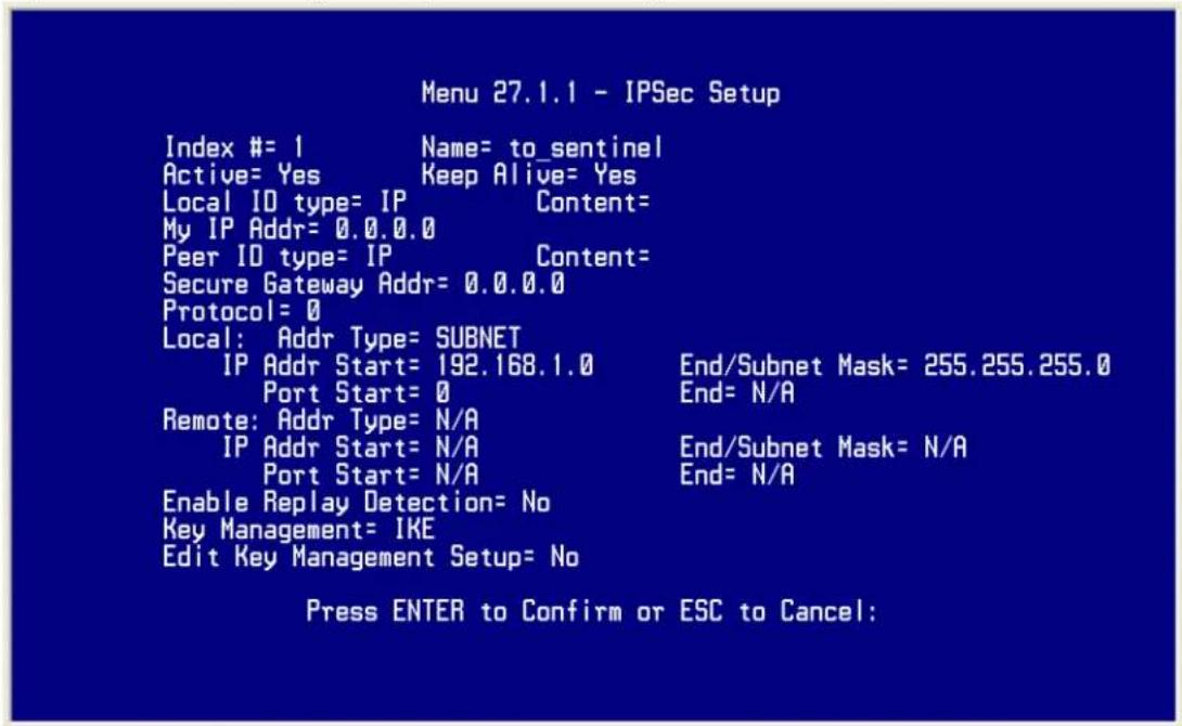
- Edit IKE settings by selecting 'Edit IKE Setup' option in menu 27.1.1 to 'Yes' and then pressing 'Enter'.
- There are two phases for IKE:
In Phase 1, two IKE peers establish a secure channel for key exchanging.
In Phase 2, two peers negotiate general purpose SAs which are secure channels for data transmission.
Please note that any configuration in 'IKE Setup' should match the settings configured in Sentinel
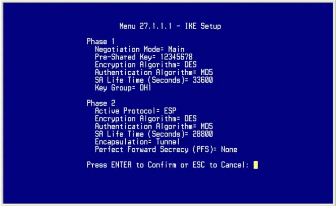
2. Setup Sentinel
- From Tool Tray of Windows system, right click on your SSH/Sentinel icon, and then choose Run Policy Editor.

- Choose Key Management. Select My Keys, then press Add... button.

- Select Create a preshared key, and press Next.

- Give this preshared key a name, P-202H Plus v2. And then enter the preshared key "12345678" in both Shared secret and Confirm shared secret fields. Finally press Finish.

- Press Apply in Main menu to save the above settings for latter use.

- Switch to Security Policy tab. Choose VPN connections, and then press Add...
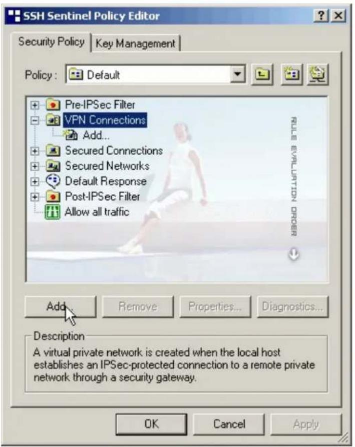
- Add VPN Connection window will pop out. Enter P-202H Plus v2.dyndns.org in Gateway IP address.
- Press ... button besides Remote network.
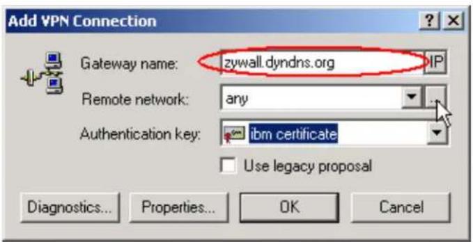
- Network Editor Window will pop out. Press New button, and Enter P-202H Plus v2 in Network name, and 192.168.1.0 in IP address field, and 255.255.255.0 in Subnet Mask field. Then click OK to go back to Add VPN Connection window.

- Choose P-202H Plus v2 as Authentication Key. Then click OK to save.
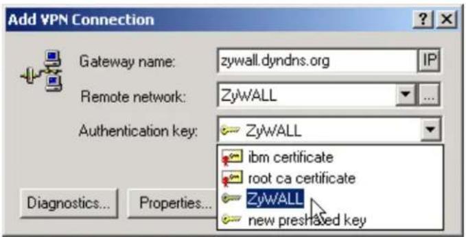
- In SSH Sentinel Policy Editor, you will get a new VPN connection, P-202H Plus v2.dyndns.org (P-202H Plus v2), choose this item, and then press Properties... button.
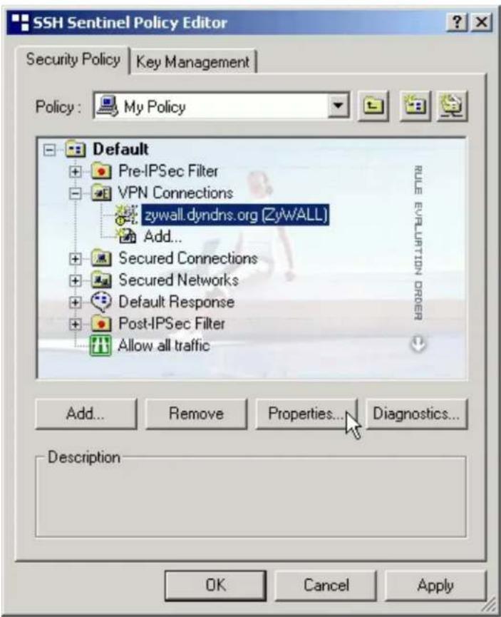
- Choose Settings button in Remote endpoint section. Please uncheck the boxes of "Acquire virtual IP address" and "Extended authentication".
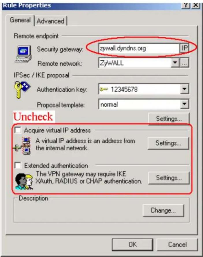
- Tune IKE proposal to Encryption algorithm as DES, Integrity function as MD5, IKE mode as main mode, IKE group as MODP 768 (group 1), and IPSec proposal to Encryption algorithm as DES, Integrity function as HMAC-MD5, PFS group as none.

- Press Apply to save all of the settings.
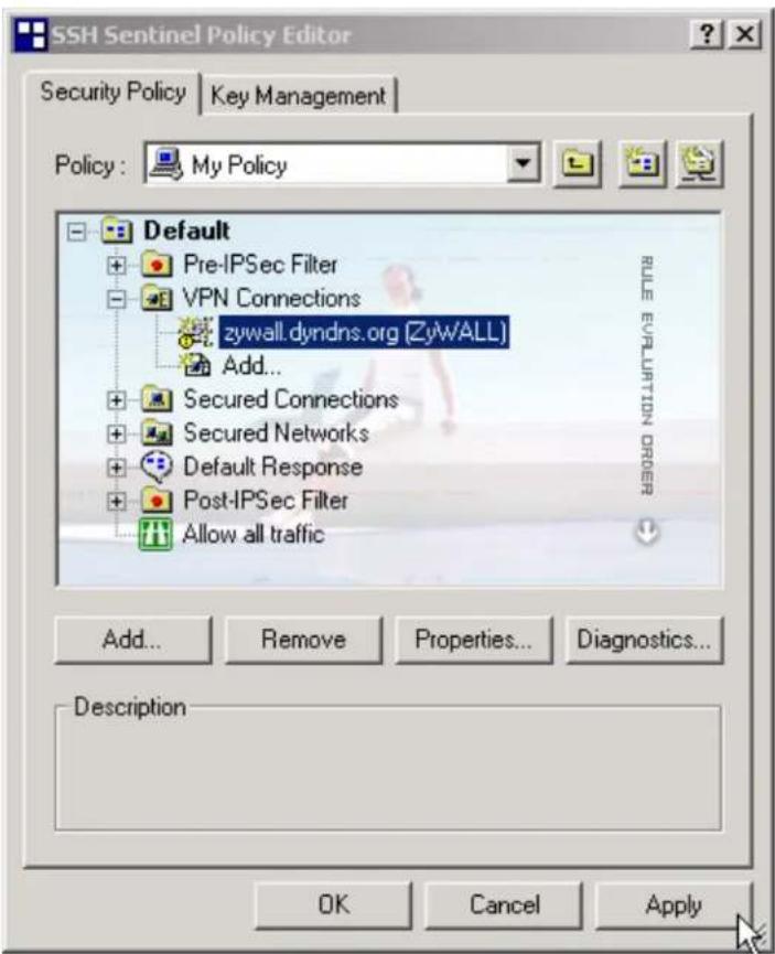
- Initiate VPN connection from Sentinel by selecting your VPN connection from Select VPN item.
Note:
A. When building VPN between Sentinel and P-202H Plus v2, the tunnel can't be initiated from P-202H Plus v2 side. Please always initiate the tunnel from Sentinel.
B. VPN tunnel on Sentinel can't be initiated by triggered packets (such as ping, ftp, telnet, HTTP...etc.) You can only initiate VPN tunnel by choosing "Select VPN" from SSH/Sentinel tray.
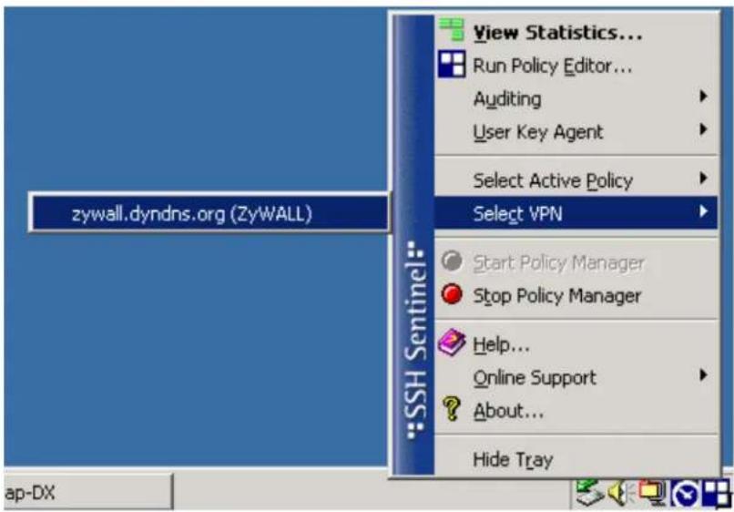
NOTE:
Please check your P-202H Plus v2's release note, if your current firmware version doesn't support Mega Bytes as SA lifetime. You have to Zero your Mega Bytes setting in SA life time. Switch to Security Policy, the configuration page is in
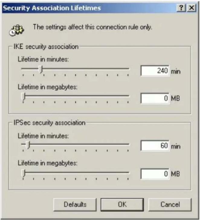
Intel VPN client to P-202H Plus v2 Tunneling
This page guides us to setup a VPN connection between the Intel VPN client software and P-202H Plus v2 router. There will be several devices we need to setup for this case. They are Intel VPN software and P-202H Plus v2 router.
As the figure shown below, the tunnel between PC 1, with Intel VPN client installed, and P-202H Plus v2 ensures the packets flow between them are secure. Because the packets go through the IPSec tunnel are encrypted. To setup this VPN tunnel, the required settings for Intel VPN client and P-202H Plus v2 are explained in the following sections. As the red pipe shown in the following figure, the tunneling endpoints are Intel VPN client and P-202H Plus v2.
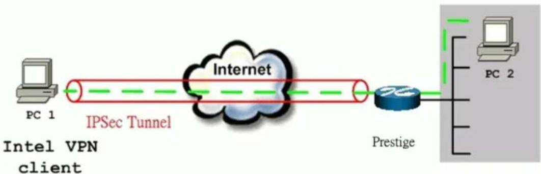
flowchart
graph LR
    A["PC 1"] -->|IPSec Tunnel| B["Internet"]
    B --> C["Prestige"]
    C --> D["PC 2"]
    style A fill:#f9f,stroke:#333
    style D fill:#bbf,stroke:#333
The IP addresses we use in this example are as shown below.
| PC 1 | P-202H Plus v2 | PC2 |
| 172.21.1.232 | LAN: 192.168.1.1WAN: 172.21.1.252 | 192.168.1.33 |
1. Setup Intel
- Select Tunnels/New.../IPSEC Tunnel to create a VPN connection.
![Intel® NetStructure(TM) VPN Client - test File View Tunnels Setup Help New... IPSEC Tunnel Delete SST Tunnel Tunnel Nar Peer IP Client IP Outbound Interface Subnet/Ma 09/19/2002 [3:59:38 PM] [keygen]: Generated 2048 bit key 09/19/2002 [3:59:38 PM] [keygen]: Generated 2048 bit key 09/19/2002 [3:59:34 PM] [keygen]: Generating 2048 bit key 09/19/2002 [3:59:33 PM] [keygen]: Generated 1024 bit key Define an IPSEC tunnel](/content/2026/02/353416/images/bb21636fc51ff10a4814f7115d1b72939755e2b9ecd8972ee8f2b2a4667b9223.jpg)
- Give this Tunnel a name, P-202H Plus v2, for example. Specify VPN Gateway IP Address as 172.21.1.252. Tunnel Applies to All network connections. Uncheck Enable IP Address assignment and WINS/DNS via VPN Gateway.
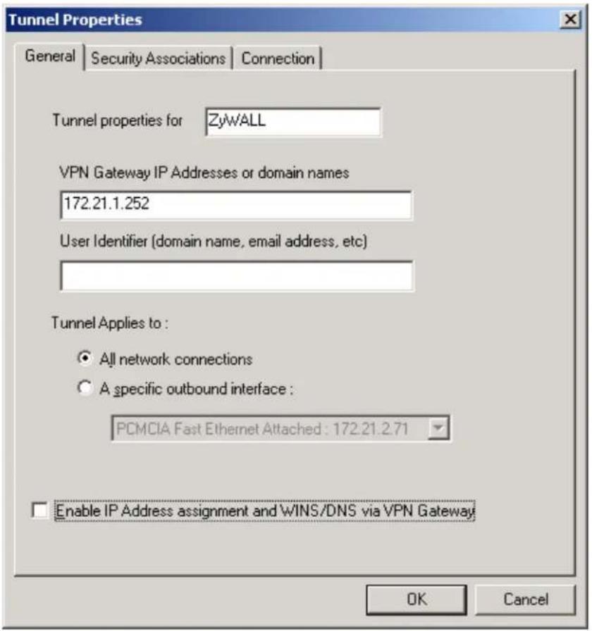
- Select Security Associations tab. Press Add... to edit the IP address of remote VPN network. IP Address 192.168.1.0, Subnet Mask 255.255.255.0, Protocol ALL, Port ALL. And Phase 2 parameters. AH None, Authentication HMAC MD5, Encryption DES (56-bit key), uncheck Transport mode. Specify the Phase 2 SA life time you would like to use. Click OK to save the settings.
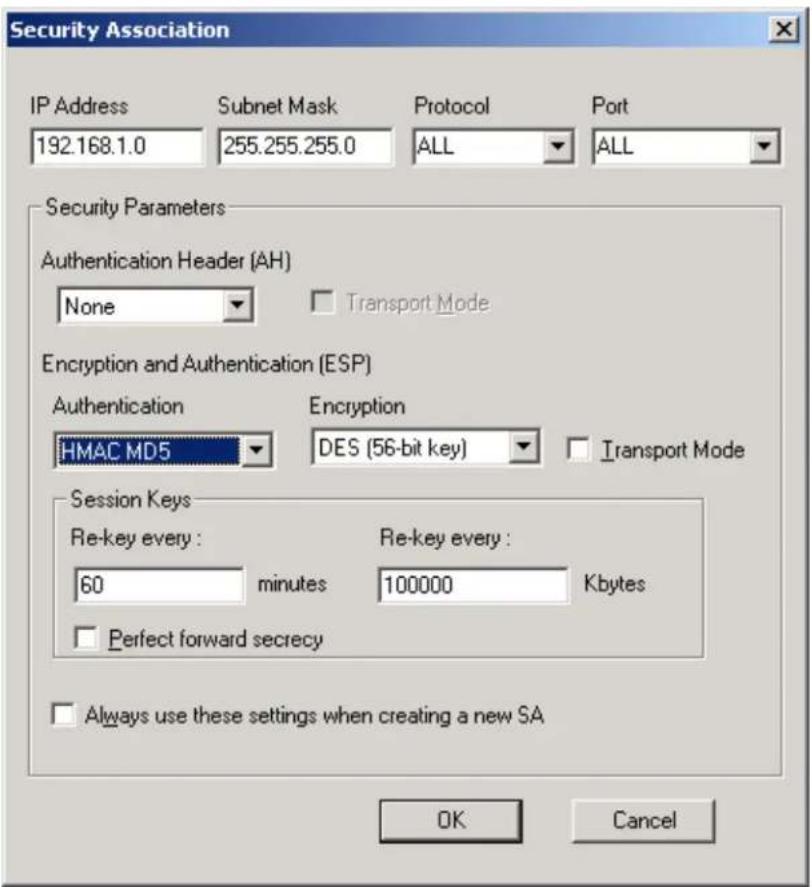
- Select Shared Secret as Authentication Method, and Enter the pre-shared key: 12345678. Then press Advanced... to edit Phase 1 parameters.
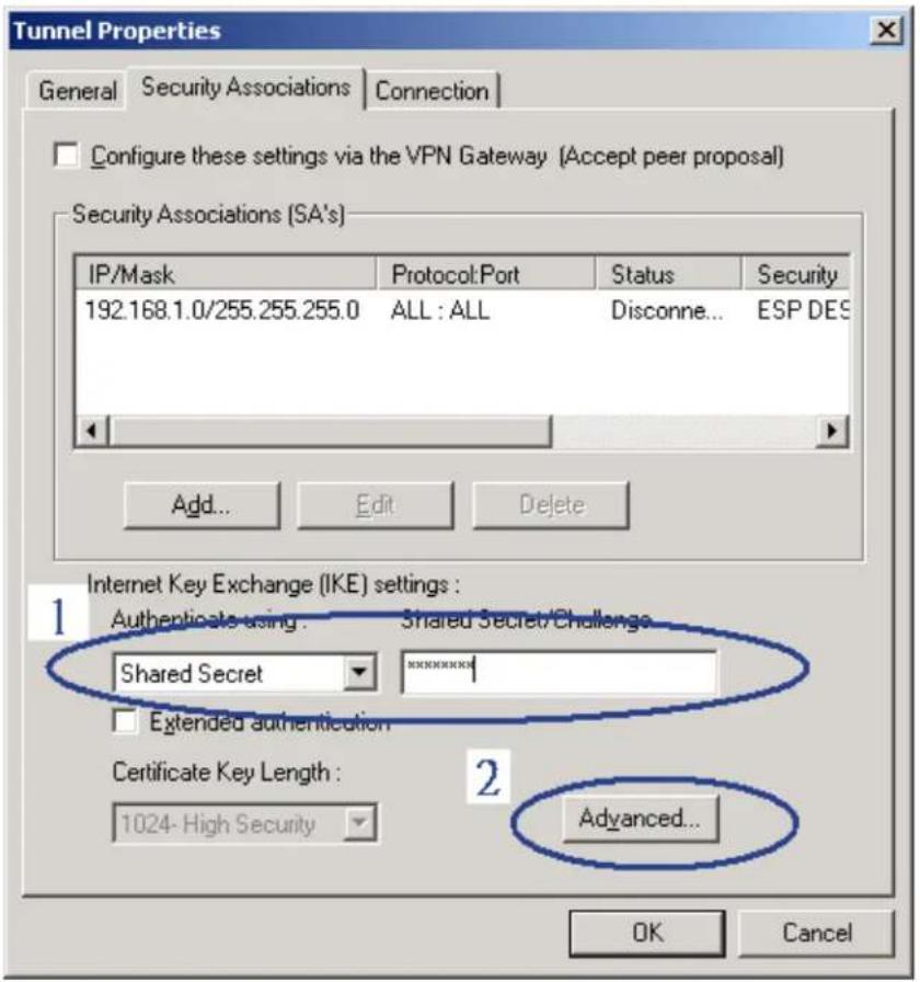
- Specify phase SA life time you would like to have, 60 minutes for example. Encryption as DES 56-bit key, Authentication as HMAC MD5, and Diffie-Hellman Group as 1-RSA 768 bits. Click OK to save.
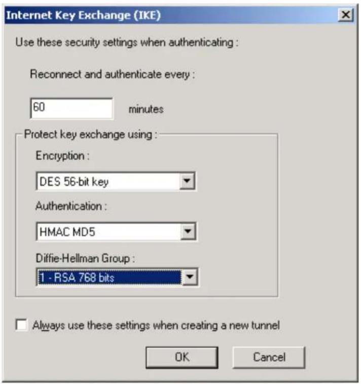
2. Setup P-202H Plus v2 VPN
- Using a web browser, login P-202H Plus v2 by giving the LAN IP address of P-202H Plus v2 in URL field. Default LAN IP is 192.168.1.1, default password to login web configurator is 1234.
- Click Advanced, and click VPN tab on the left.
- On the SUMMARY menu, Select a policy to edit by clicking Edit.
- On the CONFIGURE-IKE menu, check Active check box and give a name to this policy.
- Select IPSec Keying Mode to IKE and Negotiation Mode to Main, as we configured in SSH.
- Source IP Address Start and Source IP Address End are PC 2 IP in this example. (the secure host behind P-202H Plus v2)
- Destination IP Address Start and Destination IP Address End are PC 1 in this example. (the secure SSH PC) Note: You may assign a range of Source/Destination IP addresses for multiple VPN sessions.
- My IP Addr is the WAN IP of P-202H Plus v2.
- Secure Gateway IP Addr is the remote SSH's IP, that is PC 1 in this example.
- Select Encapsulation Mode to Tunnel.
-
Check the ESP check box. (AH can not be used in SUA/NAT case)
-
Select Encryption Algorithm to DES and Authentication Algorithm to MD5, as we configured in SSH.
- Enter the key string 12345678 in the Preshared Key text box, and click Apply.
- Press Advanced button to set IKE phase 1 and phase 2 parameters.
See the VPN rule screen shot
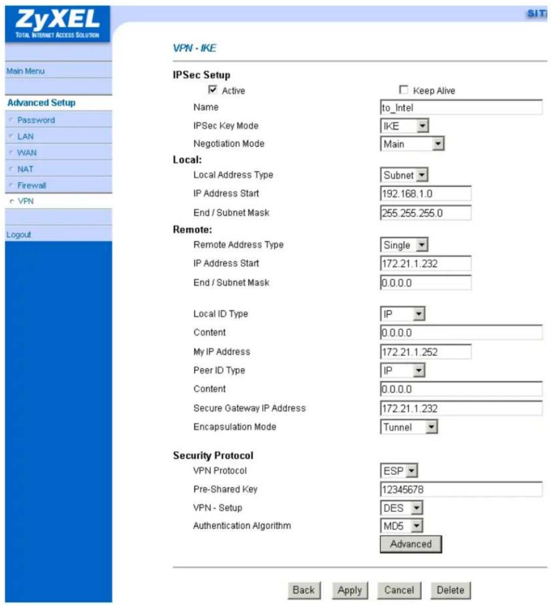
Set IKE Phase 1 and Phase 2 parameters.

VPN·IKE·Advanced Setup
VPN - IKE
Protocol
Enable Replay Detection
Local Start Port
Remote Start Port

Phase1
Negotiation Mode
Pre-Shared Key
Encryption Algorithm
Authentication Algorithm
SA Life Time (Seconds)
Key Group
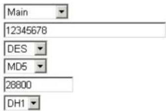
Encryption Algorithm
Authentication Algorithm
SA Life Time (Seconds)
Encapsulation
Perfect Forward Secrecy(PFS)
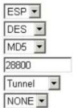
Apply Cancel
If you use SMT management, the VPN configurations are as shown below.
Menu 27.1.1 - IPSec Setup
Index #= 1 Name= to_ssh
Active= Yes
My IP Addr= 172.21.1.252
Secure Gateway Addr= 172.21.1.232
Protocol= 0
Local: Addr Type= SUBNET
IP Addr Start= 192.168.1.0 End= 255.255.255.0
Port Start=0 End=N/A
Remote: Addr Type= SINGLE
IP Addr Start= 172.21.1.232 End= N/A
Port Start= 0 End= N/A
Enable Replay Detection= No
Key Management= IKE
Edit Key Management Setup= No
Press ENTER to Confirm or ESC to Cancel:
- Edit IKE settings by selecting 'Edit IKE Setup' option in menu 27.1.1 to 'Yes' and then pressing 'Enter'.
- There are two phases for IKE:
In Phase 1, two IKE peers establish a secure channel for key exchanging. In Phase 2, two peers negotiate general purpose SAs which are secure channels for data transmission.
Please note that any configuration in 'IKE Setup' should match the settings configured in SSH
Negotiation Mode= Main
Pre-Shared Key= 12345678
Encryption Algorithm= DES
Authentication Algorithm= MD5
SA Life Time (Seconds)= 28800
Key Group= DH1
Phase 2
Active Protocol= ESP
Encryption Algorithm= DES
Authentication Algorithm= MD5
SA Life Time (Seconds)= 28800
Encapsulation= Tunnel
Perfect Forward Secrecy (PFS)= None
Press ENTER to Confirm or ESC to Cancel:
4. Configure NAT for Internal Servers
Some tips for this application:
Generally, without IPSec, to configure an internal server for outside access, we need to configure the server private IP and its service port in SUA/NAT Server Table. The NAT router then will forward the incoming connections to the internal server according to the service port and private IP entered in SUA/NAT Server Table.
However, if both NAT and IPSec is enabled in P-202H Plus v2, the edit of the table is necessary only if the connection is a non-secure connections. For secure connections, none SUA server settings are required since private IP is reachable in the VPN case. Remember, IPSec is an IP-in-IP encapsulation, the internal IP header is not translated by NAT.
For example:
Internal Server----P-202H Plus v2(NAT+IPSec)----ADSL Modem----Internet----Remote Network
5. VPN Routing between Branch Offices
This page guides us how to setup VPN routing between branch offices through headquarter. So that whenever branch office A wants to talk to branch office B, headquarter plays as a VPN relay. Users can gain benefit from such application when the scale of branch offices is very large, because no additional VPN tunnels between branch offices are needed. In this support note, we skip the detailed configuration steps for Internet access and presume that you are familiar with basic ZyNOS VPN configuration.
As the figure shown below, each branch office have a VPN tunnel to headquarter, thus PCs in branch offices can access systems in headquarter via the tunnel. Through VPN routing, P-202H Plus v2 series now provide you a solution to let PCs in branch offices talk to each other through the existing VPN tunnels concentrated on the headquarter. This feature is available in P-202H Plus v210, P-202H Plus v250 and P-202H Plus v2100.
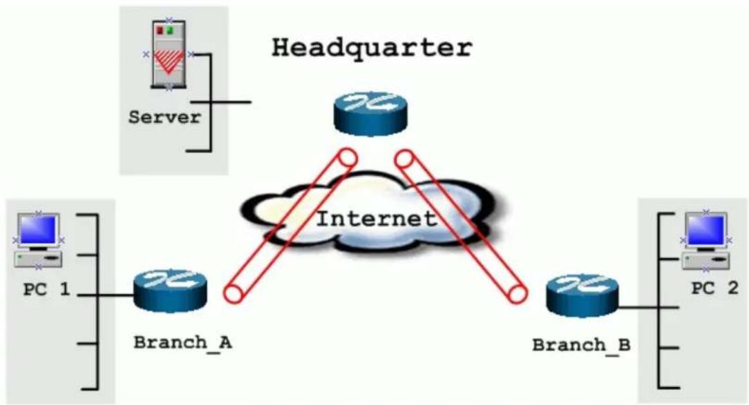
flowchart
graph TD
    A["Headquarter"] -->|Server| B["Server"]
    B --> C["PC 1"]
    C --> D["Branch_A"]
    D --> E["Internet"]
    F["PC 2"] --> G["Branch_B"]
    G --> H["Branch_A"]
    H --> I["Internet"]
The IP addresses we use in this example are as shown below.
| Branch_A | Headquarter | Branch_B |
| WAN:202.3.1.1LAN:192.168.3.1 | WAN:202.1.1.1LAN:192.168.1.1 | WAN:202.2.1.1LAN:192.168.2.1 |
| LAN of Branch_A | LAN of Headquarter | LAN of Branch_B |
| 192.168.3.0/24 | 192.168.1.0/24 | 192.168.2.0/24 |
1. Setup VPN in branch office A
Because VPN routing enables branch offices to talk to each other via tunnels concentrated on headquarter. In this step, we configure an IPSec rule in P-202H Plus v2 (Branch_A) for PCs behind branch office A to access both LAN segments of headquarter and branch office B. Because the LAN segments of headquarter and branch office B are continuous, we merge them into one single rule by including these two segments in Remote section. If by any chance, the two segments are not continuous, we strongly recommend you to setup different rules for these segments.
- Click Advanced, and click VPN tab on the left.
- On the SUMMARY menu, Select a policy to edit by clicking Edit.
- On the CONFIGURE-IKE menu, check Active check box and give a name to this policy.
- Give this VPN rule a name, Branch_A.
-
Select Key Management to IKE and Negotiation Mode to Main.
-
In Local section, select Address Type to Range Address, set IP Address Start to 192.168.3.0, and End to 192.168.3.255. This section covers the LAN segment of branch office A.
- In Remote section, select Address Type to Range Address, set IP Address Start to 192.168.1.0 and End to 192.168.2.255. This section covers the LAN segment of both headquarter and branch office B.
- My IP Addr is the WAN IP of this P-202H Plus v2, 202.3.1.1.
- Set Secure Gateway Addr to the IP address of Headquarter, 202.1.1.1.
- Select Encapsulation Mode to Tunnel.
- Check the ESP check box. (AH can not be used in SUA/NAT case)
- Select Encryption Algorithm to DES and Authentication Algorithm to SHA-1. These parameters are for IKE phase 2 negotiation. You can set more detailed configuration by pressing Advanced button.
- Enter the key string 12345678 in the Pre-shared Key text box, and click Apply.

VPN-IKE
IPSec Setup
Active
Name
IPSec Key Mode
Negotiation Mode
Local:
Local Address Type
IP Address Start
End / Subnet Mask
Remote:
Remote Address Type
IP Address Start
End / Subnet Mask
Local ID Type
Content
My IP Address
Peer ID Type
Content
Secure Gateway IP Address
Encapsulation Mode
Security Protocol
VPN Protocol
Pre-Shared Key
VPN - Setup
Authentication Algorithm
SIT
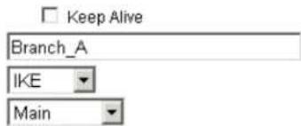
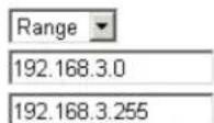
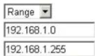
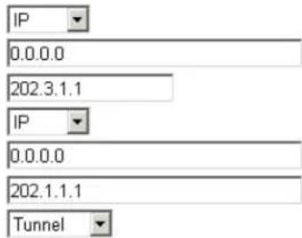
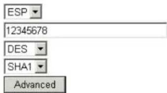

You can setup IKE phase 1 and phase 2 parameters by pressing Advanced button. Please make sure that parameters you set in this menu match with all the parameters with the correspondent VPN rule in headquarter.

2. Setup VPN in branch office B
Be very careful about the remote IP address in branch office B, because for systems behind branch office B want to systems behind branch office A and headquarter, we have to specify these two segments in Remote section. However if we include these two segments in one rule, the LAN segment of branch office B will be also included in this single rule, which means intercommunication inside branch office B will run into VPN tunnel. To avoid such situation, we need two separate rules to cover the LAN segment of branch office A and headquarter.
1. The first rule in Branch\_B.
This rule is for branch office B to access headquarter.
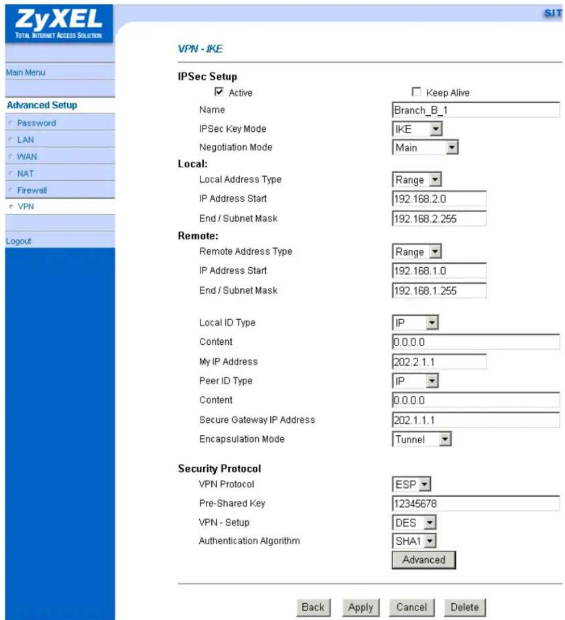
You can setup IKE phase 1 and phase 2 parameters by pressing Advanced button. Please make sure that parameters you set in this menu match with all the parameters with the correspondent VPN rule in headquarter.
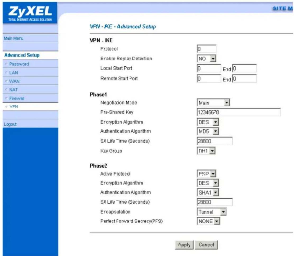
2. The second rule in Branch\_B
This rule is for branch office B to access branch office A.

You can setup IKE phase 1 and phase 2 parameters by pressing Advanced button. Please make sure that parameters you set in this menu match with all the parameters with the correspondent VPN rule in headquarter.

3. Setup VPN in Headquarter
- The correspondent rule for Branch_A in headquarter

VPN·IKE
IPSec Setup
Active
Name
IPSec Key Mode
Negotiation Mode
Local:
Local Address Type
IP Address Start
End / Subnet Mask
Remote:
Remote Address Type
IP Address Start
End / Subnet Mask
Local ID Type
Content
My IP Address
Peer ID Type
Content
Secure Gateway IP Address
Encapsulation Mode
Security Protocol
VPN Protocol
Pre-Shared Key
VPN - Setup
Authentication Algorithm
SIT
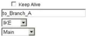
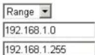
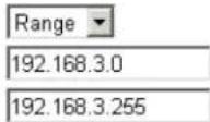
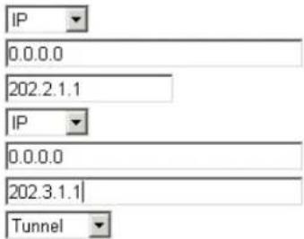
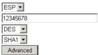


- The correspondent rule for Branch_B_1 in headquarter

VPN·IKE
IPSec Setup
Active
Name
IPSec Key Mode
Negotiation Mode
Local:
Local Address Type
IP Address Start
End / Subnet Mask
Remote:
Remote Address Type
IP Address Start
End / Subnet Mask
Local ID Type
Content
My IP Address
Peer ID Type
Content
Secure Gateway IP Address
Encapsulation Mode
Security Protocol
VPN Protocol
Pre-Shared Key
VPN - Setup
Authentication Algorithm
SIT
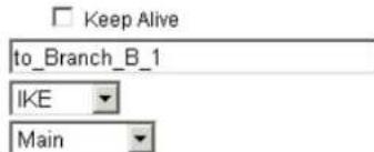
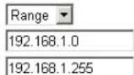
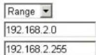
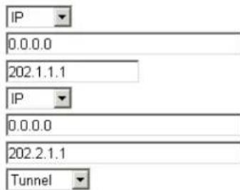
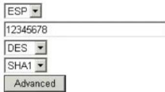
Back
Apply
Cancel
Delete
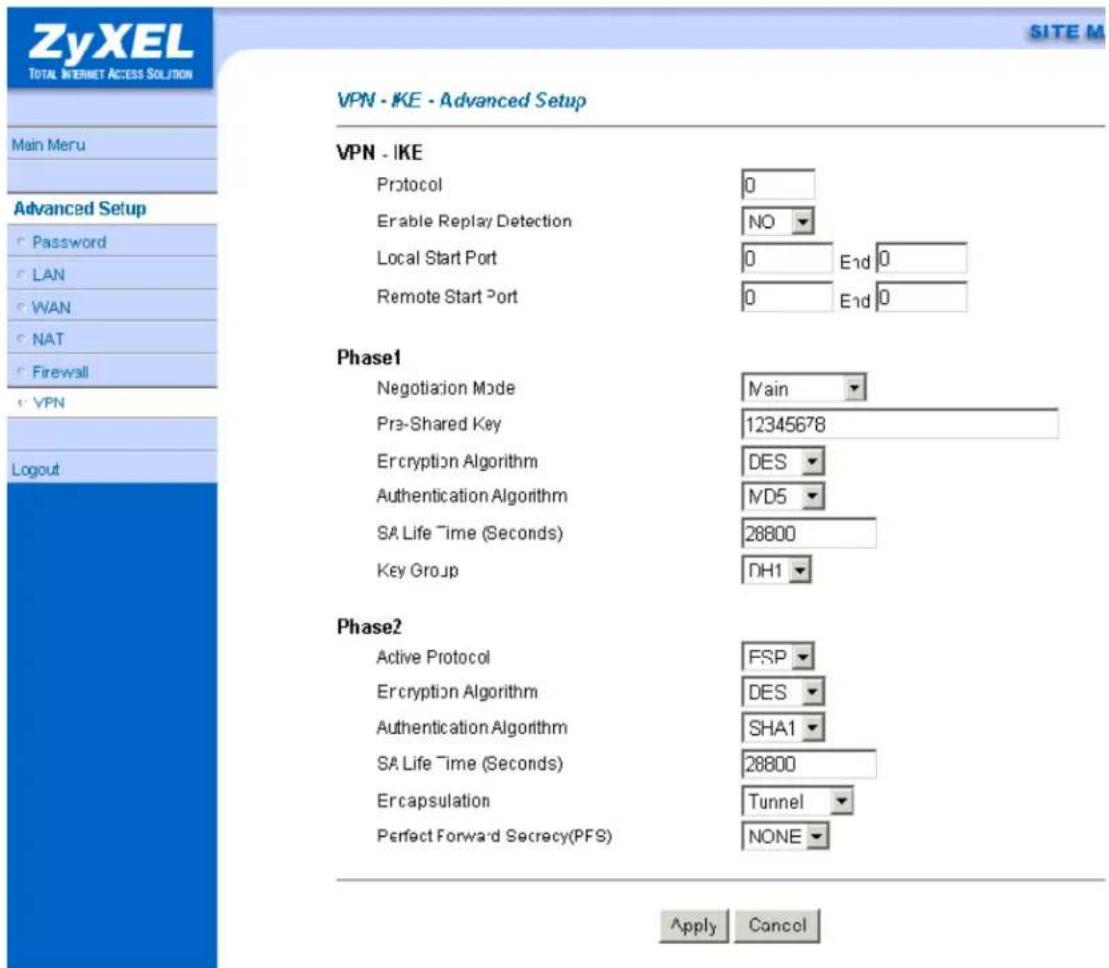
- The correspondent rule for Branch_B_2 in headquarter

VPN·IKE
IPSec Setup
Active
Name
IPSec Key Mode
Negotiation Mode
Local:
Local Address Type
IP Address Start
End / Subnet Mask
Remote:
Remote Address Type
IP Address Start
End / Subnet Mask
Local ID Type
Content
My IP Address
Peer ID Type
Content
Secure Gateway IP Address
Encapsulation Mode
Security Protocol
VPN Protocol
Pre-Shared Key
VPN - Setup
Authentication Algorithm
SIT
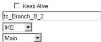
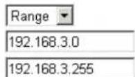
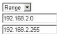
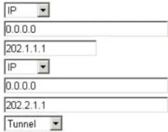
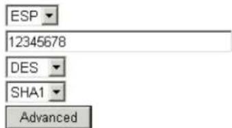

ZyXEL
TOTAL INTERNET ACCESS SOLUTION
Main Meru
Advanced Setup
| Password |
| LAN |
| WAN |
| NAT |
| Firewall |
e'VPN
Logout
SITE M
VPN·IKE·Advanced Setup
VPN - IKE
| Protocol | 0 | |
| Enable Replay Detection | NO | |
| Local Start Port | 0 | End 0 |
| Remote Start Port | 0 | End 0 |
Phase1
| Negotiation Mode | Main |
| Pre-Shared Key | 12345678 |
| Encryption Algorithm | DES |
| Authentication Algorithm | ND5 |
| SA Life Time (Seconds) | 28800 |
| Key Group | DH1 |
Phase2
| Active Protocol | FSP |
| Encryption Algorithm | DES |
| Authentication Algorithm | SHA1 |
| SA Life Time (Seconds) | 28800 |
| Ercapsulation | Tunnel |
| Perfect Forward Secrecy(PFS) | NONE |
Apply Cancel
Support Tool
1. Using ZyXEL ISDN D Channel Analyzer, EPA
Introduction
An ISDN call connection failure can be diagnosed by using P-202H Plus v2's ISDN embedded protocol analyzer (EPA). The cause code in the EPA log can also help us to diagnose the disconnection of an ISDN call.
Using EPA Analyzer
You must connect the P-202H Plus v2 to a terminal program via the serial port to capture the EPA. The EPA will not operate by Telnet. The steps for enabling the EPA are as follows:
- Enter to SMT Menu 11 and note which node N you will be dialing
- Enter to SMT Menu 24.8
- Enable the EPA capture capability by:
P-202H Plus v2>isdn fw ana on
- Manually dial to remote node N
P-202H Plus v2>dev dial N (N is the node number in Menu 11)
- Wait for all progress messages, and manually drop the call:
P-202H Plus v2>dev channel drop [bri0|bri1|all] (bri0 for B1 channel, bri1 for B2 channel, all for all channels)
- Turn off the EPA by:
P-202H Plus v2>isdn fw ana off
- Dump the EPA by:
P-202H Plus v2>isdn fw ana disp
The trace appears on the screen as in the following example. Please use PageUp and PageDown to browse the EPA trace.
Example:
P-202H Plus v2> isdn fw ana on
P-202H Plus v2> dev dial 1
Start dialing for node
### Hit any key to continue.###
\\\$ DIALING dev=2 ch=0......
\\\$ OUTGOING-CALL phone(4125678)
\\\$ CALL CONNECT speed<64000> type<2> chan<0>
\\\$ LCP opened
\\\$ PAP sending user/pswd
\\\$ IPCP negotiation started
\\\$ CCP stopped
\\\$ BACP stopped
\\\$ IPCP opened
P-202H Plus v2> dev chann drop all
P-202H Plus v2> isdn fw ana off
P-202H Plus v2> isdn fw ana disp
00:00:01:18 8 bytes LAPD D NT C SAPI=63 TEI=127UI P=0
00001111 Layer management
00000000 Reference Number,MSB:
00000000 Reference Number,LSB: 0
00000100 Message Type : Identity check request
1000000- Action indicator : 64
----1 Extension bit : final octet
00:00:03:18 8 bytes LAPD D TE C SAPI=63 TEI=127UI P=0
00001111 Layer management
00000001 Reference Number,MSB:
00000000 Reference Number,LSB: 256
00000001 Message Type : Identity request
00:00:03:19 8 bytes LAPD D NT C SAPI=63 TEI=127UI P=0
00001111 Layer management
00000001 Reference Number,MSB:
00000000 Reference Number,LSB: 256
00000010 Message Type : Identity assigned
1100001- Action indicator : 97
----1 Extension bit : final octet
00:00:03:19 3 bytes LAPD D TE C SAPI=0 TEI=97 SABME P=1
00:00:03:20 3 bytes LAPD D NT R SAPI=0 TEI=97 UA F=1
00:00:03:23 36 bytes LAPD D TE C SAPI=0 TEI=97 INFO P=0 NR=0
NS=0
28 bytes Layer 3
Orig-> CallRef=1 PD=Q.931 SETUP
1 00000100 INFORMATION ELEMENT : Bearer Capability
2 00000010 IE length : 2 bytes
3 1---- Extension bit : not continued
-00---- Coding standard : CCITT coding standard
---01000 Info. trans. cap. : Unrestricted Digit
4 1---- Extension bit : not continued
-00---- Transfer mode : Circuit Mode
---10000 Info. trans. rate : 64 kbps
1 00011000 INFORMATION ELEMENT : Channel Idetification
2 00000001 IE length : 1 byte
3 1---- Extension bit : not continued
-0---- Interface ld present: implicitly
--0---- Interface type : basic interface
---0---- Spare
---0---- Preferred/Exclusive : preferred channel
----0-- D Channel Indicator : channel identified is not D Channel
----01 Info. Ch. Selection : B1 channel
1 01101100 INFORMATION ELEMENT : Calling Party Number
2 00001001 IE length : 9 bytes
3 0---- Extension bit : continued
-000---- Type of number : unknown
----0000 Numbering plan iden.: unknown
3a 1---- Extension bit : not continued
-00---- Presentation indic. : presentation allowed
---000-- Spare
----00 Screeing indicator : user provided, not screened
***** Calling Number Type : [5009097]
1 01110000 INFORMATION ELEMENT : Called Party Number
2 00001000 IE length : 8 bytes
3 1---- Extension bit : not continued
-000---- Type of number : unknown
----0000 Numbering plan iden.: unknown
***** Called Number Type : [4125678]
00:00:03:23 4 bytes LAPD D NT R SAPI=0 TEI=97 RR P/F=0 NR=1
00:00:03:28 11 bytes LAPD D NT C SAPI=0 TEI=97 INFO P=0 NR=1
NS=0
3 bytes Layer 3
Dest-> CallRef=1 PD=Q.931 CALL_PROCE.
1 00011000 INFORMATION ELEMENT : Channel Idetification
2 00000001 IE length : 1 byte
3 1---- Extension bit : not continued
-0---- Interface ld present: implicitly
--0---- Interface type : basic interface
---0---- Spare
----1--- Preferred/Exclusive : only the channel is acceptable
----0-- D Channel Indicator : channel identified is not D Channel
----01 Info. Ch. Selection : B1 channel
00:00:03:29 4 bytes LAPD D TE R SAPI=0 TEI=97 RR P/F=0 NR=1
00:00:03:59 11 bytes LAPD D NT C SAPI=0 TEI=97 INFO P=0 NR=1
NS=1
3 bytes Layer 3
Dest-> CallRef=1 PD=Q.931 ALERTING
1 00110100 INFORMATION ELEMENT : Signal
2 00000001 IE length : 1 byte
3 01000000 Signal Value : alerting on-pattern 0
00:00:03:59 4 bytes LAPD D TE R SAPI=0 TEI=97 RR P/F=0 NR=2
00:00:03:61 23 bytes LAPD D NT C SAPI=0 TEI=97 INFO P=0 NR=1
NS=2
15 bytes Layer 3
Dest-> CallRef=1 PD=Q.931 CONNECT
1 00110100 INFORMATION ELEMENT : Signal
2 00000001 IE length : 1 byte
3 00111111 Signal Value : tones off
1 01001100 INFORMATION ELEMENT : Connected Number
2 00001010 IE length : 10 bytes
********** Unknown IE content : 0x21 0x83 0x33 0x34 0x31
********** Unknown IE content : 0x32 0x35 0x36 0x37 0x38

00:00:03:62 4 bytes LAPD D TE R SAPI=0 TEI=97 RR P/F=0 NR=3
00:00:03:63 8 bytes LAPD D TE C SAPI=0 TEI=97 INFO P=0 NR=3 NS=1
0 bytes Layer 3
Orig-> CallRef=1 PD=Q.931 CONNECT_ACK
00:00:03:63 4 bytes LAPD D NT R SAPI=0 TEI=97 RR P/F=0 NR=2
00:00:12:61 12 bytes LAPD D TE C SAPI=0 TEI=97 INFO P=0 NR=3
NS=2
4 bytes Layer 3
Orig-> CallRef=1 PD=Q.931 DISCONNECT
1 00001000 INFORMATION ELEMENT : Cause
2 00000010 IE length : 2 bytes
3 1---- Extension bit : not continued
-00---- Coding standard : CCITT coding standard
---O---- Spare
----0000 Location : user
4 1---- Extension bit : not continued

-0010000 Cause (Value) : normal call clearing

00:00:12:62 4 bytes LAPD D NT R SAPI=0 TEI=97 RR P/F=0 NR=3
00:00:12:75 12 bytes LAPD D NT C SAPI=0 TEI=97 INFO P=0 NR=3
NS=3
4 bytes Layer 3
Dest-> CallRef=1 PD=Q.931 RELEASE
1 00001000 INFORMATION ELEMENT : Cause
2 00000010 IE length : 2 bytes
3 1---- Extension bit : not continued
-00---- Coding standard : CCITT coding standard
---0---- Spare
----0000 Location : user
4 1---- Extension bit : not continued
-0010000 Cause (Value) : normal call clearing
00:00:12:76 4 bytes LAPD D TE R SAPI=0 TEI=97 RR P/F=0 NR=4
00:00:12:76 8 bytes LAPD D TE C SAPI=0 TEI=97 INFO P=0 NR=4 NS=3
0 bytes Layer 3
Orig-> CallRef=1 PD=Q.931 RLS_COMPLETE
00:00:12:77 4 bytes LAPD D NT R SAPI=0 TEI=97 RR P/F=0 NR=4
P-202H Plus v2>
2. Using ZyXEL PPP Analyzer
Introduction
The P-202H Plus v2 supports the trace of PPP log, that we can diagnose from the trace by referring to the PPP numbers or use the ZPKTTOOL to interpret for us.
P-202H Plus v2 ZPKTTOOL tool is a DOS utility that interprets the dump of the PPP log in P-202H Plus v2. A PPP call connection failure can be diagnosed by using P-202H Plus v2's PPP protocol analyzer.
Using PPP Protocol Analyzer
You must connect the P-202H Plus v2 to a terminal program via the serial port to capture the PPP log.
The PPP log will not operate by Telnet. The steps for capturing the PPP log are as follows:
- Enter to SMT Menu 11 and note which node N you will be dialing
- Enter to SMT Menu 24.8
- Enable the PPP trace capability by:
P-202H Plus v2>sys trcl cl
P-202H Plus v2>sys trcl sw on
P-202H Plus v2>sys trcp sw on
- Manually dial to remote node N
P-202H Plus v2>dev dial N (N is the node number in Menu 11)
Example:
Prestige> dev dial 1
Start dialing for node <hinet>...
<h3 id="hit-any-key-to-continue">Hit any key to continue.###</h3>
$$$ DIALING dev=2 ch=0......
$$$ OUTGOING-CALL phone(4125678)
$$$ CALL CONNECT speed<64000> type<2>
chan<0>
$$$ LCP opened
$$$ PAP sending user/pswd
$$$ IPCP negotiation started
$$$ CCP stopped
- Wait for all progress messages, and manually drop the call:
P-202H Plus v2>dev channel drop [bri0|bri1] (bri0 for B1 channel, bri1 for B2 channel)
- Turn off the PPP trace by:
P-202H Plus v2>sys trcl sw off
P-202H Plus v2>sys trcp sw off
- Dump the PPP log by:
P-202H Plus v2>sys trcl disp
The trace appears on the screen as in the following example. Press
Example:
P-202H Plus v2> dev chan drop bri0
P-202H Plus v2> sys trcl sw off
P-202H Plus v2> sys trcp sw off
P-202H Plus v2> sys trcl disp
87 258407 PP08 DIALING dev=2 ch=0......
88 258407 PP08 OUTGOING-CALL phone(4125678)
89 258470 PP08 CALL CONNECT speed<64000> type<2> chan<0>
90 258471 PP09 ebp=7ea690, seqNum=5c bri0-XMIT len:23 call=4
0000: ff 03 c0 21 01 0d 00 13 01 04 05 f4 05 06 00 03
0010: f1 a6 08 02 0d 03 06
91 258748 PP09 ebp=7ea6c4, seqNum=5d bri0-XMIT len:23 call=4
0000: ff 03 c0 21 01 0e 00 13 01 04 05 f4 05 06 00 03
0010: f1 a6 08 02 0d 03 06
92 258750 PP09 ebp=7ea6f8, seqNum=5e bri0-RECV len:29 call=4
0000: ff 03 c0 21 01 01 00 19 01 04 05 f4 03 04 c0 23
0010: 11 04 05 f4 13 09 03 00 c0 7b 72 cf 08
93 258751 PP09 ebp=7ea72c,seqNum=5f bri0-XMIT len:21 call=4
0000: ff 03 c0 21 04 01 00 11 11 04 05 f4 13 09 03 00
0010: c0 7b 72 cf 08
94 258751 PP09 ebp=7ea760,seqNum=60 bri0-RECV len:13 call=4
0000: ff 03 c0 21 04 0e 00 09 08 02 0d 03 06
95 258751 PP09 ebp=7e9dd4,seqNum=61 bri0-XMIT len:18 call=4
0000: ff 03 c0 21 01 0f 00 0e 01 04 05 f4 05 06 00 03
0010: f1 a6
96 258753 PP09 ebp=7e9e08,seqNum=62 bri0-RECV len:16 call=4
0000: ff 03 c0 21 01 02 00 0c 01 04 05 f4 03 04 c0 23
97 258753 PP09 ebp=7e9e3c, seqNum=63 bri0-XMIT len:16 call=4
0000: ff 03 c0 21 02 02 00 0c 01 04 05 f4 03 04 c0 23
98 258754 PP09 ebp=7e9e70,seqNum=64 bri0-RECV len:18 call=4
0000: ff 03 c0 21 02 0f 00 0e 01 04 05 f4 05 06 00 03
0010: f1 a6
99 258754 PP09 LCP opened
100 258754 PP09 PAP sending user/pswd
101 258754 PP09 ebp=7e9ea4,seqNum=65 bri0-XMIT len:25 call=4
0000: ff 03 c0 23 01 10 00 15 07 7a 79 78 65 6c 72 64
0010: 08 70 72 65 73 74 69 67 65
102 258759 PP09 ebp=7e9ed8,seqNum=66 bri0-RECV len:9 call=4
0000: ff 03 c0 23 02 10 00 05 00
103 258759 PP09 IPCP negotiation started
104 258760 PP09 ebp=7e9f0c,seqNum=67 bri0-XMIT len:20 call=4
0000: ff 03 80 21 01 19 00 10 02 06 00 2d 0f 00 03 06
0010: 00 00 00 00
105 258760 PP09 ebp=7e9f40,seqNum=68 bri0-RECV len:20 call=4
0000: ff 03 80 21 01 01 00 10 02 06 00 2d 0f 01 03 06
0010: a8 5f 43 2b
106 258760 PP09 ebp=7e9f74,seqNum=69 bri0-XMIT len:20 call=4
0000: ff 03 80 21 02 01 00 10 02 06 00 2d 0f 01 03 06
0010: a8 5f 43 2b
107 258760 PP09 ebp=7e9fa8,seqNum=6a bri0-RECV len:14 call=4
0000: ff 03 80 fd 01 01 00 0a 11 06 00 01 01 03
108 258760 PP09 ebp=7e9fdc, seqNum=6b bri0-XMIT len:20 call=4
| 0000: ff 03 c0 21 08 11 00 10 80 fd 01 01 00 0a 11 06 | |
| 0010: 00 01 01 03 | |
| 109 | 258761 PP09 ebp=7ea010, seqNum=6c bri0-RECV len:14 call=4 |
| 0000: ff 03 80 21 03 19 00 0a 03 06 a3 1f f4 2e | |
| 110 | 258761 PP09 ebp=7ea044, seqNum=6d bri0-XMIT len:20 call=4 |
| 0000: ff 03 80 21 01 1a 00 10 02 06 00 2d 0f 00 03 06 | |
| 0010: a3 1f f4 2e | |
| 111 | 258763 PP09 ebp=7ea078, seqNum=6e bri0-RECV len:20 call=4 |
| 0000: ff 03 80 21 02 1a 00 10 02 06 00 2d 0f 00 03 06 | |
| 0010: a3 1f f4 2e | |
| 112 | 258763 PP09 IPCP opened |
| 113 | 260465 PP09 FSM_DOWN state=9 |
| 114 | 260465 PP09 LCP closed |
| 115 | 260465 PP09 FSM_DOWN state=9 |
| 116 | 260465 PP09 IPCP closed |
| 117 | 260465 PP09 FSM_DOWN. state=1 |
| 118 | 260465 PP09 FSM_DOWN state=1 |
| 119 | 260465 PP09 FSM_DOWN. state=1 |
| 120 | 260465 PP09 FSM_DOWN state=0 |
| 121 | 260465 PP09 FSM_DOWN. state=0 |
| 122 | 260465 PP09 FSM_DOWN state=0 |
| 123 | 260465 PP09 FSM_DOWN. state=0 |
| 124 | 260465 PP09 FSM_DOWN state=0 |
| 125 | 260465 PP09 FSM_DOWN. state=0 |
| 126 | 260465 PP09 FSM_DOWN. state=1 |
| 127 | 260465 PP09 PPP down chan<0>, 0 |
Program Trace Switch OFF
Packet Trace Switch OFF
P-202H Plus v2>
- Copy and paste the trace to an editor and save it as a text file
- Run the ZPKTTOOL program to interpret the PPP log, to know the detailed trace, please refer to the ppp numbers.
![MS-DOS Prompt - ZPKTTOOL 7 x 12 ZyXEL ZPKTTOOL Ver 0.13 (98103D) 473K | ASC [ 18 336][ 0] t:\ppp.txt 0 258748 BRIO-XMIT [0023] LCP (ID=0x0e) Configure-Request (1,5,8,13) 1 258750 BRIO-RECU [0029] LCP (ID=0x01) Configure-Request (1,3,17,19) 2 258751 BRIO-XMIT [0021] LCP (ID=0x01) Configure-Reject (17,19) 3 258751 BRIO-RECU [0013] LCP (ID=0x0e) Configure-Reject (8,13) 4 258751 BRIO-XMIT [0018] LCP (ID=0x0f) Configure-Request (1,5) 5 258753 BRIO-RECU [0016] LCP (ID=0x02) Configure-Request (1,3) 6 258753 BRIO-XMIT [0016] LCP (ID=0x02) Configure-Ack (1,3) 7 258754 BRIO-RECU [0018] LCP (ID=0x0f) Configure-Ack (1,5) 8 258754 BRIO-XMIT [0025] PAP (ID=0x10) Authenticate 9 258759 BRIO-RECU [0009] PAP (ID=0x10) Authenticate-Ack 10 258760 BRIO-XMIT [0020] IPCP (ID=0x19) Configure-Request (2,3) 11 258760 BRIO-RECU [0020] IPCP (ID=0x01) Configure-Request (2,3) 12 258760 BRIO-XMIT [0020] IPCP (ID=0x01) Configure-Ack (2,3) 13 258760 BRIO-RECU [0014] CCP (ID=0x01) Configure-Request (17) 14 258760 BRIO-XMIT [0020] LCP (ID=0x11) Protocol-Reject 15 258761 BRIO-RECU [0014] IPCP (ID=0x19) Configure-Mak (3) 16 258761 BRIO-XMIT [0020] IPCP (ID=0x1a) Configure-Request (2,3) 17 258763 BRIO-RECU [0020] IPCP (ID=0x1a) Configure-Ack (2,3) [ 18 OK] [ 0] F1=HEX F2=LoadLog F3=SaveLog F4=CIr F5=Load F6=Save ESC=Quit By David Chen](/content/2026/02/353416/images/00bc81d3d759681f28172826d16f1114a83f821e4eca77e444d62d1487e27162.jpg)
3. LAN/WAN Packet Trace
The P-202H Plus v2 records packet trace and analyzes packets running on LAN and WAN interfaces. It is designed for users with technical backgrounds who are interested in the details of the packet flow on LAN or WAN end of the P-202H Plus v2. It is also very helpful for diagnostics if you have compatibility problems with your ISP or if you want to know the details of a packet for configuring a filter rule.
The format of the display is as following:
Packet:
0 11880.160 ENET0-R[0062] TCP 192.168.1.2:1108->192.31.7.130:80
[index] [timer/second][channel-receive/transmit][length] [protocol] [sourceIP/port] [destIP/port]
There are two ways to dump the trace:
- Online Trace--display the trace real time on screen
- Offline Trace--capture the trace first and display later
The details for capturing the trace in SMT menu 24.8 are as follows.
Online Trace
- Trace LAN packet
-
Trace WAN packet
-
Trace LAN packet
1.1 Disable to capture the WAN packet by entering: sys trcp channel [bri0|bri1] none
1.2 Enable to capture the LAN packet by entering: sys trcp channel enet0 bothway
1.3 Enable the trace log by entering: sys trcp sw on & sys trcl sw on
1.4 Display the brief trace online by entering: sys trcd brief
or
1.5 Display the detailed trace online by entering: sys trcd parse
Example:
ras> sys trcp channel bri0 none
ras> sys trcp channel enet0 bothway
ras> sys trcp sw on
ras> sys trcl sw on
ras> sys trcd brief
0 11880.160 ENET0-R[0062] TCP 192.168.1.2:1108->192.31.7.130:80
1 11883.100 ENET0-R[0062] TCP 192.168.1.2:1108->192.31.7.130:80
2 11883.330 ENET0-T[0058] TCP 192.31.7.130:80->192.168.1.2:1108
3 11883.340 ENET0-R[0060] TCP 192.168.1.2:1108->192.31.7.130:80
4 11883.340 ENET0-R[0339] TCP 192.168.1.2:1108->192.31.7.130:80
5 11883.610 ENET0-T[0054] TCP 192.31.7.130:80->192.168.1.2:1108
6 11883.620 ENET0-T[0102] TCP 192.31.7.130:80->192.168.1.2:1108
7 11883.630 ENET0-T[0054] TCP 192.31.7.130:80->192.168.1.2:1108
8 11883.630 ENET0-R[0060] TCP 192.168.1.2:1108->192.31.7.130:80
9 11883.650 ENET0-R[0060] TCP 192.168.1.2:1108->192.31.7.130:80
10 11883.650 ENET0-R[0062] TCP 192.168.1.2:1109->192.31.7.130:80
ras> sys trcd parse
----<0000>
LAN Frame: ENET0-RECV Size: 62/ 62 Time: 12089.790 sec
Frame Type: TCP 192.168.1.2:1116->192.31.7.130:80

Ethernet Header:
Destination MAC Addr = 00AOC5921311
Source MAC Addr = 008OC84CEA63
Network Type = 0x0800 (TCP/IP)

IP Header:
IP Version = 4
Header Length = 20
Type of Service = 0x00 (0)
Total Length = 0x0030 (48)
Idetification = 0x330B (13067)
Flags = 0x02
Fragment Offset = 0x00
Time to Live = 0x80 (128)
Protocol = 0x06 (TCP)
Header Checksum = 0x3E71 (15985)
Source IP = 0xC0A80102 (192.168.1.2)
Destination IP = 0xC01F0782 (192.31.7.130)
TCP Header:
Source Port = 0x045C (1116)
Destination Port = 0x0050 (80)
Sequence Number = 0x00BD15A7 (12391847)
Ack Number = 0x00000000 (0)
Header Length = 28
Flags = 0x02 (....S.)
Window Size = 0x2000 (8192)
Checksum = 0xBEC3 (48835)
Urgent Ptr = 0x0000 (0)
Options =
0000: 02 04 05 B4 01 01 04 02
RAW DATA:
0000: 00 A0 C5 92 13 11 00 80-C8 4C EA 63 08 00 45 00 .....L.c..E.
0010: 00 30 33 0B 40 00 80 06-3E 71 C0 A8 01 02 C0 1F .03.@...>q.....
0020: 07 82 04 5C 00 50 00 BD-15 A7 00 00 00 00 70 02 ...P......p.
0030: 20 00 BE C3 00 00 02 04-05 B4 01 01 04 02
--<0001>
LAN Frame: ENET0-XMIT Size: 58/58 Time: 12090.020 sec
Frame Type: TCP 192.31.7.130:80->192.168.1.2:1116
Ethernet Header:
Destination MAC Addr = 0080C84CEA63
Source MAC Addr = 00A0C5921311
Network Type = 0x0800 (TCP/IP)
IP Header:
IP Version = 4
Header Length = 20
Type of Service = 0x00 (0)
Total Length = 0x002C (44)
Idetification = 0x57F3 (22515)
Flags = 0x02
Fragment Offset = 0x00
Time to Live = 0xED (237)
Protocol = 0x06 (TCP)
Header Checksum = 0xAC8C (44172)
Source IP = 0xC01F0782 (192.31.7.130)
Destination IP = 0xC0A80102 (192.168.1.2)
TCP Header:
Source Port = 0x0050 (80)
Destination Port = 0x045C (1116)
Sequence Number = 0x4AD1B57F (1255257471)
Ack Number = 0x00BD15A8 (12391848)
Header Length = 24
Flags = 0x12 (.A..S.)
Window Size = 0xFAF0 (64240)
Checksum = 0xF877 (63607)
Urgent Ptr = 0x0000 (0)
Options =
0000: 02 04 05 B4
RAW DATA:
0000: 00 80 C8 4C EA 63 00 A0-C5 92 13 11 08 00 45 00 ...L.c.....E.
0010: 00 2C 57 F3 40 00 ED 06-AC 8C C0 1F 07 82 C0 A8 ,W.@......
0020: 01 02 00 50 04 5C 4A D1-B5 7F 00 BD 15 A8 60 12 ...P.\J......
0030: FA F0 F8 77 00 00 02 04-05 B4 ...w.....
--<0002>
LAN Frame: ENET0-RECV Size: 60/ 60 Time: 12090.210 sec
Frame Type: TCP 192.168.1.2:1116->192.31.7.130:80
Ethernet Header:
Destination MAC Addr = 00A0C5921311
Source MAC Addr = 0080C84CEA63
Network Type = 0x0800 (TCP/IP)
IP Header:
IP Version = 4
Header Length = 20
Type of Service = 0x00 (0)
Total Length = 0x0028 (40)
Idetification = 0x350B (13579)
Flags = 0x02
Fragment Offset = 0x00
Time to Live = 0x80 (128)
Protocol = 0x06 (TCP)
Header Checksum = 0x3C79 (15481)
Source IP = 0xC0A80102 (192.168.1.2)
Destination IP = 0xC01F0782 (192.31.7.130)
TCP Header:
Source Port = 0x045C (1116)
Destination Port = 0x0050 (80)
Sequence Number = 0x00BD15A8 (12391848)
Ack Number = 0x4AD1B580 (1255257472)
Header Length = 20
Flags = 0x10 (.A....)
Window Size = 0x2238 (8760)
Checksum = 0xE8ED (59629)
Urgent Ptr = 0x0000 (0)
TCP Data: (Length=6, Captured=6)
1.1 Disable to capture the LAN packet by entering: sys trcp channel enet0 none
1.2 Enable to capture the WAN packet by entering: sys trcp channel [bri0|bri1] bothway
1.3 Enable the trace log by entering: sys trcp sw on & sys trcl sw on
1.4 Display the brief trace online by entering: sys trcd brief or
1.5 Display the detailed trace online by entering: sys trcd parse
Example:
ras> sys trcp channel enet0 none
ras> sys trcp channel bri0 bothway
ras> sys trcp sw on
ras> sys trcl sw on
ras> sys trcd brief
0 899.160 BRI0-T[0023] LCP (ID=0x05) Configure-Request (1,5,8,13)
1 902.120 BRI0-T[0023] LCP (ID=0x06) Configure-Request (1,5,8,13)
2 905.120 BRI0-T[0023] LCP (ID=0x07) Configure-Request (1,5,8,13)
3 905.150 BRI0-R[0029] LCP (ID=0x01) Configure-Request (1,3,17,19)
4 905.150 BRI0-T[0021] LCP (ID=0x01) Configure-Reject (17,19)
5 905.160 BRI0-R[0013] LCP (ID=0x07) Configure-Reject (8,13)
5 905.160 BRI0-R[0013] LCP (ID=0x07) Configure-Reject (8,13)
ras> sys trcd parse
<0000>
PPP Frame: BRI0-XMIT Size: 52/ 52 Time: 1145.250 sec
Frame Type: TCP 163.31.239.1:10007->210.67.113.145:80
PPP Header:
Protocol = 0x0021 (IP)
IP Header:
IP Version = 4
Header Length = 20
Type of Service = 0x00 (0)
Total Length = 0x0030 (48)
Idetification = 0xE702 (59138)
Flags = 0x02
Fragment Offset = 0x00
Time to Live = 0x7F (127)
Protocol = 0x06 (TCP)
Header Checksum = 0x3ECF (16079)
Source IP = 0xA31FEF01 (163.31.239.1)
Destination IP = 0xD2437191 (210.67.113.145)
TCP Header:
Source Port = 0x2717 (10007)
Destination Port = 0x0050 (80)
Sequence Number = 0x000BCB53 (772947)
Ack Number = 0x00000000 (0)
Header Length = 28
Flags = 0x02 (....S.)
Window Size = 0x2000 (8192)
Checksum = 0x9A63 (39523)
Urgent Ptr = 0x0000 (0)
Options =
0000: 02 04 05 B4 01 01 04 02
RAW DATA:
0000: FF 03 00 21 45 00 00 30-E7 02 40 00 7F 06 3E CF ...IE..0..@...>.0010: A3 1F EF 01 D2 43 71 91-27 17 00 50 00 0B CB 53 ....Cq.'.P...S
0020: 00 00 00 00 70 02 20 00-9A 63 00 00 02 04 05 B4 ....p. ..c.....
0030: 01 01 04 02 ....
--<0001>
PPP Frame: BRI0-RECV Size: 48/ 48 Time: 1147.970 sec
Frame Type: TCP 210.67.113.145:80->163.31.239.1:10007
PPP Header:
Protocol = 0x0021 (IP)
IP Header:
IP Version = 4
Header Length = 20
Type of Service = 0x00 (0)
Total Length = 0x002C (44)
Idetification = 0xB0D4 (45268)
Flags = 0x02
Fragment Offset = 0x00
Time to Live = 0x38 (56)
Protocol = 0x06 (TCP)
Header Checksum = 0xBC01 (48129)
Source IP = 0xD2437191 (210.67.113.145)
Destination IP = 0xA31FEF01 (163.31.239.1)
TCP Header:
Source Port = 0x0050 (80)
Destination Port = 0x2717 (10007)
Sequence Number = 0x7AA71C33 (2057772083)
Ack Number = 0x000BCB54 (772948)
Header Length = 24
Flags = 0x12 (.A..S.)
Window Size = 0x4470 (17520)
Checksum = 0xF40E (62478)
Urgent Ptr = 0x0000 (0)
Options =
0000: 02 04 05 B4
RAW DATA:
0000: FF 03 00 21 45 00 00 2C-B0 D4 40 00 38 06 BC 01 ...!E...,.@.8...
0010: D2 43 71 91 A3 1F EF 01-00 50 27 17 7A A7 1C 33 .Cq.....P'.z..3
0020: 00 0B CB 54 60 12 44 70-F4 0E 00 00 02 04 05 B4 ...T'.Dp......
Offline Trace
- Trace LAN packet
-
Trace WAN packet
-
Trace LAN packet
1.1 Disable to capture the WAN packet by entering: sys trcp channel [bri0|bri1] none
1.2 Enable to capture the LAN packet by entering: sys trcp channel enet0 bothway
1.3 Enable the trace log by entering: sys trcp sw on & sys trcl sw on
1.4 Wait for packet passing through P-202H Plus v2 over LAN
1.5 Disable the trace log by entering: sys trcp sw off & sys trcl sw off
1.6 Display the trace briefly by entering: sys trcp brief
1.7 Display specific packets by using: sys trcp parse
Exmaple:
ras> sys trcp channel bri0 none
ras> sys trcp channel enet0 bothway
ras> sys trcp sw on
ras> sys trcl sw on
ras> sys trcp sw off
ras> sys trcl sw off
ras> sys trcp brief
0 10855.790 ENET0-T[0141] TCP 192.31.7.130:80->192.168.1.2:1102
1 10855.800 ENET0-R[0060] TCP 192.168.1.2:1102->192.31.7.130:80
2 10855.810 ENET0-R[0062] TCP 192.168.1.2:1103->192.31.7.130:80
3 10855.840 ENET0-R[0062] TCP 192.168.1.2:1104->192.31.7.130:80
4 10856.020 ENET0-T[0054] TCP 192.31.7.130:80->192.168.1.2:1102
5 10856.030 ENET0-T[0058] TCP 192.31.7.130:80->192.168.1.2:1103
6 10856.040 ENET0-R[0060] TCP 192.168.1.2:1103->192.31.7.130:80 ras> sys trcp parse 5 5
--<0005>
LAN Frame: ENET0-XMIT Size: 58/58 Time: 10856.030 sec
Frame Type: TCP 192.31.7.130:80->192.168.1.2:1103
Ethernet Header:
Destination MAC Addr = 0080C84CEA63
Source MAC Addr = 00A0C5921311
Network Type = 0x0800 (TCP/IP)
IP Header:
IP Version = 4
Header Length = 20
Type of Service = 0x00 (0)
Total Length = 0x002C (44)
Idetification = 0x7F02 (32514)
Flags = 0x02
Fragment Offset = 0x00
Time to Live = 0xED (237)
Protocol = 0x06 (TCP)
Header Checksum = 0x857D (34173)
Source IP = 0xC01F0782 (192.31.7.130)
Destination IP = 0xC0A80102 (192.168.1.2)
TCP Header:
Source Port = 0x0050 (80)
Destination Port = 0x044F (1103)
Sequence Number = 0xD91B1826 (3642431526)
Ack Number = 0x00AA405F (11157599)
Header Length = 24
Flags = 0x12 (.A..S.)
Window Size = 0xFAF0 (64240)
Checksum = 0xDCEF (56559)
Urgent Ptr = 0x0000 (0)
Options = 0000: 02 04 05 B4
RAW DATA:
0000: 00 80 C8 4C EA 63 00 A0-C5 92 13 11 08 00 45 00 ...L.c.....E.
0010: 00 2C 7F 02 40 00 ED 06-85 7D C0 1F 07 82 C0 A8 ,..@...}.....
0020: 01 02 00 50 04 4F D9 1B-18 26 00 AA 40 5F 60 12 ...P.O...&..@_.
0030: FA F0 DC EF 00 00 02 04-05 B4 ......
as>
2. Trace WAN packet
1.1 Disable to capture the LAN packet by entering: sys trcp channel enet0 none
1.2 Enable to capture the WAN packet by entering: sys trcp channel [bri0|bri1] bothway
1.3 Enable the trace log by entering: sys trcp sw on & sys trcl sw on
1.4 Wait for packet passing through P-202H Plus v2 over WAN
1.5 Disable the trace log by entering: sys trcp sw off & sys trcl sw off
1.6 Display the trace briefly by entering: sys trcp brief
1.7 Display specific packets by using: sys trcp parse
Example:
ras> sys trcp channel enet0 none
ras> sys trcp channel bri0 bothway
ras> sys trcl sw on
ras> sys trcp sw on
ras> sys trcl sw off
ras> sys trcp sw off
ras> sys trcp brief
0 1181.540 BRI0-T[0011] PPP VJ Compressed IP (0x002d)
1 1182.840 BRI0-T[0044] TCP 163.31.239.1:10007->210.67.113.145:80
2 1226.450 BRI0-T[0052] TCP 163.31.239.1:10008->210.67.113.145:80
3 1226.480 BRI0-R[0048] TCP 210.67.113.145:80->163.31.239.1:10008
4 1226.480 BRI0-T[0044] IP Unknown (0x07)
5 1226.490 BRI0-T[0446] PPP VJ Compressed IP (0x002d)
ras> sys trcp parse 1 2
<0002>
PPP Frame: BRI0-XMIT Size: 52/ 52 Time: 1226.450 sec
Frame Type: TCP 163.31.239.1:10008->210.67.113.145:80
PPP Header:
Protocol = 0x0021 (IP)
IP Header:
IP Version = 4
Header Length = 20
Type of Service = 0x00 (0)
Total Length = 0x0030 (48)
Idetification = 0xFD02 (64770)
Flags = 0x02
Fragment Offset = 0x00
Time to Live = 0x7F (127)
Protocol = 0x06 (TCP)
Header Checksum = 0x28CF (10447)
Source IP = 0xA31FEF01 (163.31.239.1)
Destination IP = 0xD2437191 (210.67.113.145)
TCP Header:
Source Port = 0x2718 (10008)
Destination Port = 0x0050 (80)
Sequence Number = 0x000D088D (854157)
Ack Number = 0x00000000 (0)
Header Length = 28
Flags = 0x02 (....S.)
Window Size = 0x2000 (8192)
Checksum = 0x5D27 (23847)
Urgent Ptr = 0x0000 (0)
Options =
0000: 02 04 05 B4 01 01 04 02
RAW DATA:
0000: FF 03 00 21 45 00 00 30-FD 02 40 00 7F 06 28 CF ...!E..0..@...(.
0010: A3 1F EF 01 D2 43 71 91-27 18 00 50 00 0D 08 8D .....Cq.'..P....
0020: 00 00 00 00 70 02 20 00-5D 27 00 00 02 04 05 B4 ....p. .]'.....
0030: 01 01 04 02 ....
--<0003>
PPP Frame: BRI0-RECV Size: 48/ 48 Time: 1226.480 sec
Frame Type: TCP 210.67.113.145:80->163.31.239.1:10008
PPP Header:
Protocol = 0x0021 (IP)
IP Header:
IP Version = 4
Header Length = 20
Type of Service = 0x00 (0)
Total Length = 0x002C (44)
Idetification = 0x01D3 (467)
Flags = 0x02
Fragment Offset = 0x00
Time to Live = 0x38 (56)
Protocol = 0x06 (TCP)
Header Checksum = 0x6B03 (27395)
Source IP = 0xD2437191 (210.67.113.145)
Destination IP = 0xA31FEF01 (163.31.239.1)
TCP Header:
Source Port = 0x0050 (80)
Destination Port = 0x2718 (10008)
Sequence Number = 0x7F47963C (2135397948)
Ack Number = 0x000D088E (854158)
Header Length = 24
Flags = 0x12 (.A..S.)
Window Size = 0x4470 (17520)
Checksum = 0x3829 (14377)
Urgent Ptr = 0x0000 (0)
Options =
0000: 02 04 05 B4
RAW DATA:
0000: FF 03 00 21 45 00 00 2C-01 D3 40 00 38 06 6B 03 ...!E...,.@.8.k.
0010: D2 43 71 91 A3 1F EF 01-00 50 27 18 7F 47 96 3C .Cq.....P'..G.<
0020: 00 0D 08 8E 60 12 44 70-38 29 00 00 02 04 05 B4 ....`.Dp8)......
ras>
Using TFTP to Upload/Download Firmware and Configuration Files
4. Using TFTP to upload/download ZyNOS via LAN
- TELNET to your P-202H Plus v2 first before running the TFTP software
○ Type the CI command 'sys stdio 0' to disable console idle timeout in Menu 24.8 and stay in Menu 24.8 - Run the TFTP client software
- Enter the IP address of the P-202H Plus v2
To upload the firmware, please save the remote file as 'ras' to P-202H Plus v2. After the transfer is complete, the P-202H Plus v2 will program the upgraded firmware into FLASH ROM and reboot itself.
To download the firmware, please get the remote file 'ras' from the P-202H Plus v2.
An example:
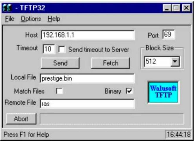
The 192.168.1.1 is the IP address of the P-202H Plus v2. The local file is the source file of the ZyNOS firmware that is available in your hard disk. The remote file is the file name that will be saved in P-202H Plus v2. Check the port number 69 and 512-Octet blocks for TFTP. Check 'Binary' mode for file transferring.
Using TFTP to upload/download SMT configurations via LAN
- TELNET to your P-202H Plus v2 first before running the TFTP software
○ Type the CI command 'sys stdio 0' to disable console idle timeout in Menu 24.8 and stay in Menu 24.8 - Run the TFTP client software
To download the SMT configuration, please get the remote file 'rom-0' from the P-202H Plus v2.
To upload the SMT configuration, please save the remote file as 'rom-0' in the P-202H Plus v2.
An Example:
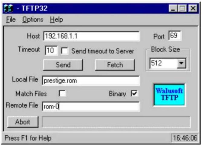
The 192.168.1.1 is the IP address of the P-202H Plus v2.
- The local file is the source file of your configuration file that is available in your hard disk.
- The remote file is the file name that will be saved in P-202H Plus v2.
- Check the port number 69 and 512-Octet blocks for TFTP.
- Check 'Binary' mode for file transferring.
• Using TFTP command on Windows NT
Before you begin:
- TELNET to your P-202H Plus v2 first before using TFTP command
- Type the CI command 'sys stdio 0' to disable console idle timeout in Menu 24.8 and stay in Menu 24.8
- Upload ZyNOS via LAN
c:\tftp -i [P-202H Plus v2IP] put [localfile] ras
- Download ZyNOS via LAN
c:\tftp -i [P-202H Plus v2IP] get ras [localfile]
- Upload SMT configurations via LAN
c:\tftp -i [P-202H Plus v2IP] put [localfile] rom-0
- Download SMT configurations via LAN
c:\tftp -i [P-202H Plus v2IP] get rom-0 [localfile]
• Using TFTP command on UNIX
Before you begin:
- TELNET to your P-202H Plus v2 first before using TFTP command
- Type the CI command 'sys stdio 0' to disable console idle timeout in Menu 24.8 and stay in Menu 24.8
Example:
[cppwu@faelinux cppwu]\$ telnet 192.168.1.1
Trying 192.168.1.1...
Connected to 192.168.1.1.
Escape character is '^]'.
Password: ****
Copyright (c) 1999 ZyXEL Communications Corp.
P-202H Plus v2 Main Menu
Getting Started
- General Setup
- ISDN Setup
- Ethernet Setup
- Internet Access Setup
Advanced Management
-
Filter Set Configuration
-
System Password
-
System Maintenance
Advanced Applications
- Remote Node Setup
- Static Routing Setup
- Default Dial-in Setup
- Dial-in User Setup
-
SUA Server Setup
-
Exit
Enter Menu Selection Number:24
Menu 24 - System Maintenance
- System Status
- System Information and Console Port Speed
- Log and Trace
- Diagnostic
- Backup Configuration
- Restore Configuration
- Software Update
- Command Interpreter Mode
- Call Control
Copyright (c) 1999 ZyXEL Communications Corp.n Number: 8
ras> sys stdio 0
ras> (press Ctrl+] to escape to Telnet prompt)
telnet> z
[1]+ Stopped telnet 192.168.1.1
[cppwu@faelinux cppwu]\$ tftp
tftp> connect 192.168.1.1
tftp> binary <- change to binary mode
tftp> get rom-0 [local-rom] <- download configurations
tftp> get ras [local-firmware] <- download firmware
tftp> put [local-rom] rom-0 <- upload configurations
tftp> put [local-firmware] ras <- upload firmware
5. Using FTP to Upload Firmware and Configuration Files
In addition to upload the firmware and configuration file via the console port and TFTP client, you can also upload the firmware and configuration files to the P-202H Plus v2 202 using FTP.
To use this feature, your workstation must have a FTP client software. There are two examples as shown below.
1. Using FTP command in terminal
| Step 1 | Use FTP client from your workstation to connect to the P-202H Plus v2 by entering the IP address of the P-202H Plus v2. |
| Step 2 | Press 'Enter' key to ignore the username, because the P-202H Plus v2 does not check the username. |
| Step 3 | Enter the SMT password as the FTP login password, the default is '1234'. |
| Step 4 | Enter command 'bin' to set the transfer type to binary. |
| Step 5 | Use 'put' command to transfer the file to the P-202H Plus v2. |
Note: The remote file name for the firmware is 'ras' and for the configuration file is 'rom-0' (rom-zero, not capital o).
Example:
C:\temp>ftp 202.132.155.97
Connected to 202.132.155.97.
220 FTP version 1.0 ready at Thu Jan 1 00:02:09 1970
User (202.132.155.97:(none)): <Enter>
331 Enter PASS command
Password:****
230 Logged in
ftp> bin
200 Type I OK
ftp> put p202e.bin ras
200 Port command okay
150 Opening data connection for STOR ras
226 File received OK
ftp: 924512 bytes sent in 4.83Seconds 191.41Kbytes/sec.
ftp>
Here, the 'p202e.bin' is the local file and 'ras' is the remote file that will be saved in the P-202H Plus v2.
The P-202H Plus v2 reboots automatically after the uploading is finished.
2. Using FTP client software
| Step 1 | Rename the local firmware and configuration files to 'ras' and 'rom-0', because we can not specify the remote file name in the FTP client software. |
| Step 2 | Use FTP client from your workstation to connect to the P-202H Plus v2 by entering the IP address of the P-202H Plus v2. |
| Step 3 | Enter the SMT password as the FTP login password. The default is '1234'. |
| Step 4 | Press 'OK' key to ignore the username, because the P-202H Plus v2 does not check the username. |
Example:
- Connect to the P-202H Plus v2 by entering the P-202H Plus v2's IP and SMT password in the FTP software. Set the transfer type to 'Auto-Detect' or 'Binary'.
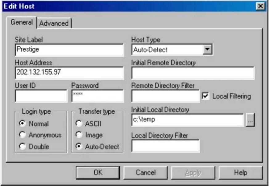
- Press 'OK' to ignore the 'Username' prompt.

- To upload the firmware file, we transfer the local 'ras' file to overwrite the remote 'ras' file.
To upload the configuration file, we transfer the local 'rom-0' to overwrite the remote 'rom-0' file.
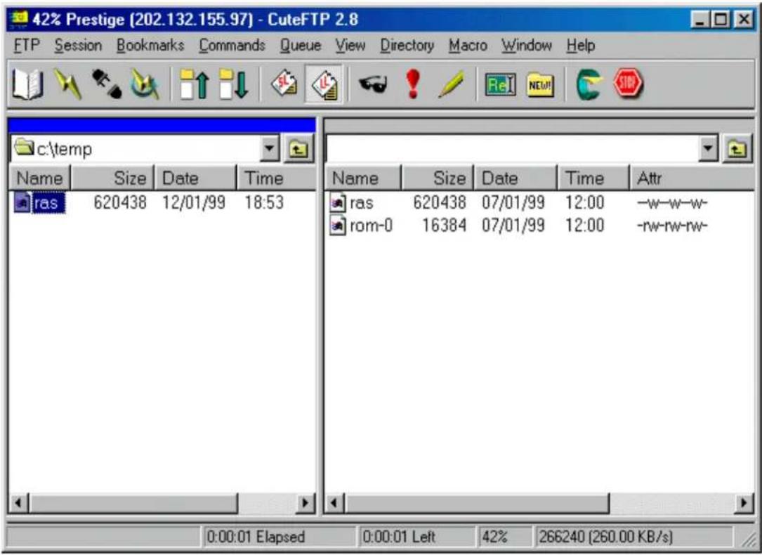
- The P-202H Plus v2 reboots automatically after the uploading is finished.
CI Command List
CI has the following command syntax:
command
General user interface:
| 1. | ? | Shows the following commands and all major (sub)commands |
| 2. | exit | Exit Subcommand |
To get the latest CI Command list
The latest CI Command list is available in release note of every ZyXEL firmware release. Please goto ZyXEL public WEB site http://www.zyxel.com/support/download_index.php to download firmware package (*.zip), you should unzip the package to get the release note in PDF format.
Troubleshooting
1. Internet Connection
Related SMT screens and CI commands:
- SMT Menu 1, 4
- SMT Menu 24.1 and 24.4
-isdn loop
-dev dial
Some basic knowledge about Internet Connection Setup
Before we start any verification or troubleshooting of Internet setup, let us first give a brief introduction of the connection setup sequence. Any PPP call to Internet or other (ISDN) router can be divided into the following steps:
- Dialing
- LCP negotiation
- Authentication ( it can be None/PAP/CHAP)
- NCP negotiation (NCP can be IPCP, BACP, BCP, CCP, IPXCP)
The P-202H Plus v2 provides a very clear log for each step of the call setup. The following shows the messages displayed in each steps. If a step fails, an error message is displayed.
Start Dialing chan<1> phone<20301> <---- Dialing
Call CONNECT speed<64000> type<2> chan<0> <---- Dial OK
( After call is up, P-202H Plus v2 will start LCP negotiation )
LCP opened <---- Lcp OK
CHAP login to remote OK! <---- Auth OK
IPCP negotiation started <---- Ipcp negotiation
BACP negotiation started
***BCP stopped <---- Bcp Not available
CCP stopped <---- Ccp Not available
IPCP opened <---- IPCP OK
BACP opened <---- Bacp OK
Internet connection verification steps:
- Setup Menu 4 for Internet Access.
• Perform a connection test (after you save Menu 4). - You should see the call connected, LCP up or opened, CHAP/PAP login OK and IPCP up or opened.
Internet connection test failed:
- Setup Menu 4 for Internet Access,
- Perform a connection test (after you save Menu 4). You could get the following errors.
Some common problem troubleshooting examples
- Cannot make outcall
- Login to remote failed
• IP address been rejected by your ISP
• ISDN protocol mismatch - Disconnect by far-end
- Other unknown reason
- Call didn't connect - Try again later and also verify the phone number.
- Cannot make outcall
Dial no number
This could mean that your ISDN line is not up.
Dial Fail *** LINK IS NOT AVAILABLE
This could mean that your two channels are connected to other sites (or A/B adapter in use).
- Call didn't connect - Try again later and also verify the phone number.
Dialing chan<1> phone(last 9-digit): 40202
Hit any key to continue.###
Dial no answer
This means the far-end is not answering.
Dialing chan<1> phone(last 9-digit): 40202
<h3 id="hit-any-key-to-continue-3">Hit any key to continue.###</h3>
Dial busy
This means the far-end is busy.
Dialing chan<1> phone(last 9-digit): 40202
<h3 id="hit-any-key-to-continue-4">Hit any key to continue.###</h3>
Dial timeout
This means you have been timeed out in making a connection. Please refer to next chapter for more detailed discussion on this.
- Login to remote failed
Dialing chan<1> phone (last 9-digit): 40201
<h3 id="hit-any-key-to-continue-5">Hit any key to continue.###</h3>
Call CONNECT speed<64000> type<2> chan<0>
LCP opened
CHAP login to remote failed
LCP closed
Recv'd TERM-REQ
Recv'd TERM-ACK state 5
LCP stopped
TRY: Verify username and password with your ISP again or retype the username and password field again. When you retype the name and password and hit return at 'Press Enter to confirm or Esc to Cancel', if you don't see 'Saving to ROM' message, then your original entry is the same as your retry, this means maybe the name/pw from the ISP is incorrect. You must call your ISP and verify the name and password again.
- IP address been rejected by your ISP
Dialing chan<1> phone (last 9-digit): 40201
<h3 id="hit-any-key-to-continue-6">Hit any key to continue.###</h3>
Call CONNECT speed<64000> type<2> chan<0>
LCP opened
CHAP login to remote OK! IPCP negotiation started IPCP opened Recv'd TERM-ACK state 4 LCP stopped
sys log disp:
"PP09 WARN Local IP mismatch, proposed 192.68.135.183, PP09 WARN neg'd 204.247.1.1, make sure RIP is turned on"
This means that you configured your P-202H Plus v2 Menu 3.2 as 192.68.135.183, but the ISP thinks you should be 204.247.1.1. The P-202H Plus v2 dropped the call for you, because even if the call is up, your network will still be unable to talk to the Internet!
TRY: 1. If you have a class C network of 204.247.1.0/24, then you should change your Menu 3.2 to use that address. 2. If you have only one IP address 204.247.1.1/32, then you should configure your P-202H Plus v2 to enable Single User Account (SUA) (For more information on how to configure SUA, please refer to application note.)
- ISDN protocol mismatch
Dialing chan<1> phone (last 9-digit): 40201
Hit any key to continue.###
Call CONNECT speed<64000> chan<1> prot<1>
You see the call connected, but nothing else after that. After a while it says Line down. This could be because of the low level protocol mismatch. Let's say you use 64K to dial into a X.75 or V.120 only router.
TRY: Contact your ISP and make sure they use 'Clear Channel' ISDN protocol, or change your Telco option to X.75 or V.120 (for DSS1 or 1TR6 only).
- Disconnect by far-end
Dialing chan<1> phone (last 9-digit): 40201
Hit any key to continue.###
Call CONNECT speed<64000> chan<1> prot<1> LCP up
| CHAP send response |
| CHAP login to remote OK! |
| IPCP negotiation started |
| BACP stopped |
| IPCP up |
| LCP down |
| IPCP down |
| LCP stopped |
The call connected, IPCP was up, but still the call dropped. The call could have been dropped by the far-end for some unknown reason. You need to verify the problem with your ISP. Sometimes if the far-end is using Ascend Pipeline for your connection, they will let IPCP up and check the IP address, if IP address is not the same as what's configured in their 'Connection Profile', they would drop the call and give no log about it!
- Other unknown reason
For any other unknown reason, you have to look at the packet trace to decide what went wrong. To collect the trace,
- Go to Menu 11, and mark down which remote number # is for Internet access.
- Go to CI (Menu 24.8)
- Turn on the screen capture/log capability
- sys trcl cl ( to clear the trace )
- sys trcl sw on ( to turn on the trace log )
- sys trcp sw on ( to turn on the packet trace )
- dev dial #
• After the call failed - sys trcl disp
Summary:
| Failure reasons Actions | |
| Dial failed - check disconnect cause- go to SMT memu 24.1 to verify that channel status is not DOWN. If DOWN, it might be ISDN Init failure.- Do ISDN loopback test | |
| Authentication failed - check name and password | |
| Lcp negotiation failed - trace PPP packets | |
| Ipcp negotiation failed - check if IP address is correct- check if IP is turned on in a remote node.- check if SUA is needed | |
| All others - collect PPP traces | |
2. Remote Node/Dial-in User Connection
Related SMT screens and CI commands:
- SMT Menu 2
- SMT Menu 24.4.12
- SMT Menu 24.9
- isdn dial # (pre-ZyNOS) or dev dial # (ZyNOS)
- sys log disp
Cannot outcall to a Remote node
Use CI "isdn dial
The following are some possible failure reasons for a outgoing call:
- Dial failed (please refer to previous chapter for more details.)
- ISDN protocol mismatched (please refer to previous chapter for more details.)
- Incoming only remote node, check Menu 11
- Pre-ZyNOS:
P2864> isdn dial 1
* Dial not allowed, or No Channel (Call to a incoming only remote node, or no free B chan)
### Hit any key to continue.###
- ZyNOS:
Zyxel> dev dial 1
<h3 id="hit-any-key-to-continue-hit-any-key">Hit any key to continue.### (hit any key)</h3>
Dial Fail *** (null)
Zyxel> sys log disp
Zyxel> PP09 ERROR netMakeChannDial: err=-3001 rn_p=575de0 (here 3001 means call out not allowed)
Some common troubleshooting examples:
• Phone number is in Black List, check Menu 24.9.2
• Call exceeded the Call budget, check Menu 24.9.3
- Login to remote node failed, check the name and password again
- PPP negotiation failed
• IP address mismatched
- Phone number is in Black List, check Menu 24.9.2
- Pre-ZyNOS:
P2864> isdn dial 1
Start dialing for node<1>
***Call failed, number is Blacklisted
<h3 id="hit-any-key-to-continue-9">Hit any key to continue.###</h3>
• ZyNOS:
Zyxel> dev dial 1
$$$ Call is blocked
- Call exceeded the Call budget, check Menu 24.9.3
- Pre-ZyNOS:
P2864> isdn dial 1
Start dialing for node<1>
***Connect time exceeds budget
***startDialing failed
Hit any key to continue.###
- ZyNOS:
Zyxel> dev dial 1 Dial no budget Zyxel> sys log disp PP09 INFO Remote node 0 budget expired PP09 INFO Dial no budget
- Login to remote node failed, check the name and password again
- Pre-ZyNOS:
P2864> isdn dial 1 Start dialing for node<1> Dialing chan<1> phone(last 9-digit):40201### Hit any key to continue.### Call CONNECT speed<64000> chan<1> prot<1> LCP up CHAP send response ***Login to remote failed. Check name/passwd. Receive Terminate REQ LCP down Line Down chan<1>
- ZyNOS:
zyxel> dev dial 1 Start dialing for node<1> Dialing chan<1> phone(last 9-digit):40201### Hit any key to continue.### Call CONNECT speed<64000> type<2> chan<0> LCP opened CHAP login to remote failed LCP closed Recv'd TERM-REQ Recv'd TERM-ACK state 5 LCP stopped
- PPP negotiation failed
306Z> isdn dial 1 or dev dial 1
Start dialing for node<1>
Dialing chan<1> phone(last 9-digit):40201### Hit any key to continue.###
Call CONNECT speed<64000> chan<1> prot<1>
LCP up
CHAP send response
CHAP login to remote OK!
IPCP negotiation started
BACP negotiation started
BACP up
CHAP send response
CHAP login to remote OK!
In the above case, the IPCP negotiation has started, but there is no 'IPCP up' message. This means that the IP negotiation failed, and even though the line is up, you can't ping from one end to the other. To identify the problem you must collect the PPP negotiation trace. Following are the steps to collect PPP negotiation packets. (You can use these steps to collect traces for all PPP related problems.)
P128> sys trcl cl
Program Trace Switch OFF
P128> sys trcl sw on
P128> sys trcp sw on
P128> isdn dial 1 or dev dial 1
Start dialing for node<1>
Dialing chan<1> phone(last 9-digit):40201### Hit any key to continue.###
Call CONNECT speed<64000> chan<1> prot<1>
LCP up
CHAP send response
CHAP login to remote OK!
IPCP negotiation started
BACP negotiation started
BACP up
P128> sys trcl disp
102 fe3792 15e PDI1 dialer Dialing chan<1> phone(last 9-digit):40201
103 fe3ea4 169 PDI1 dialer Call CONNECT speed<64000> chan<1> p
104 fe3eb8 0 POU1 ebp=4aa00,seqNum=17 PPP1-XMIT:24 len:40
0000: ff 03 c0 21 01 12 00 24 01 04 05 f4 02 06 00 00
0010: 00 00 08 02 0d 03 06 11 04 05 f4 13 09 03 00 a0
105 fe3f30 0 PNET ebp=4aa30, seqNum=18 PPP1-RECV:24 len:42
0000: ff 03 c0 21 01 30 00 26 01 04 05 f4 02 06 00 00
0010: 00 00 03 05 c2 23 05 08 02 11 04 05 f4 13 09 03
106 fe3f3a 0 POU1 ebp=4aa60, seqNum=19 PPP1-XMIT:24 len:42
0000: ff 03 c0 21 02 30 00 26 01 04 05 f4 02 06 00 00
0010: 00 00 03 05 c2 23 05 08 02 11 04 05 f4 13 09 03
107 fe3f44 0 PNET ebp=4aa90, seqNum=1a PPP1-RECV:24 len:40
0000: ff 03 c0 21 02 12 00 24 01 04 05 f4 02 06 00 00
0010: 00 00 08 02 0d 03 06 11 04 05 f4 13 09 03 00 a0
108 fe3f44 186 PNET ppp LCP up
109 fe3fc6 0 PNET ebp=4aac0, seqNum=1b PPP1-RECV:24 len:15
0000: c2 23 01 11 00 0d 08 00 00 48 e4 00 04 fc 6c
110 fe3fc6 190 PNET ppp CHAP send response
111 fe3fdo 0 POU1 ebp=4aafO, seqNum=1c PPP1-XMIT:24 len:28
0000: c2 23 02 11 00 1a 10 ce f1 4c 9f fe o1 a9 85 04
0010: bb ob b51 e5 17e5e5e5e5e5e5e5e5e5e5e5e5e5e5e5e5e5e5e5e5e5e5e5e5e5e5e5e5e5e5e5e5e5e5e5e5e5e5e5e5e5e5e5e5e5e5e5e5e5e5e
112 fe4oou2 0 PNET ebp=4ab2o, seqNum=1d PPP1-RECV:24 len:13
00oo: c2 23 03 11 0Dob b576S6c636f6d6s
113 fe4oou2 195 PNET ppp CHAP login to remote OK!
114 fe4ooc c o PNET ebp=4ab5o, seqNum=1e PPP1-RECV:24 len:8
ooo: c o29o132ooo6o1o2
115 fe4ooc c o POU1 ebp=4ab8o, seqNum=1f PPP1-XMIT:24 len:8
ooo: c o29o232ooo6o1o2
116 fe4o2a c o PNET ebp=4abbO, seqNum=2O PPP1-RECV:24 len:8
ooo: c o29o332ooo6o1o2
117 fe4o34 225 PNET ppp IPCP negotiation started
118 fe4o3e c o POU1 ebp=4abeO, seqNum=2I PPP1-XMIT:24 len:18
ooo:8o2l o1b oO bO oO bO oO bO oO bO oO bO oO bO oO bO oO bO oO bO oO bO oO bO oO bO oO bO oO bO oO bO oO bO oO bO oO bO oO bO oO bO oO bO oO bO oO bO oO bO oO bO oO bQ
ooo:cbb7
119 fe4o3e c d7 PNET ppp BACP negotiation started
12o fe4o48 c o POU1 ebp=4acIO, seqNum=2A PPP1-XMIT:24 len:12
ooo:8o7l oIb Oa aIb Oa aIb Oa aIb Oa aIb Oa aIb Oa aIb Oa aIb Oa aIb Oa aIb Oa aIb Oa aIb Oa aIb Oa aIb Oa aIb Oa aIb Oa aIb Oa aIb Oa aIb Oa aIb Oa aIb Oa
0010: 00 2d 0f 01 03 06 cc f7 cb b7
126 fe4066 0 PNET ebp=4ad30, seqNum=28 PPP1-RECV:24 len:12
0000: 80 71 02 13 00 0a 01 06 00 00 00 01
127 fe4066 2d8 PNET ppp BACP up
Program Trace Switch OFF
Packet Trace Switch OFF
From the packet trace above, one can tell why the IPCP protocol was rejected by the far end. Please refer to PPP training material for more details. (RFC 1661)
- IP address mismatched
- Pre-ZyNOS:
P128> isdn dial 4
Start dialing for node<4>
Dialing chan<1> phone(last 9-digit):40201### Hit any key to continue.###
Call CONNECT speed<64000> chan<1> prot<1>
LCP up
CHAP send response
CHAP login to remote OK!
IPCP negotiation started
BACP negotiation started
IPCP up
***Remote subnet mismatch, cfg'd 100.0.0.0
***Remote subnet mismatch, neg'd 200.0.0.0
LCP down
IPCP down
***Ip route: code=05 P1=00 P2=00 P3=00
Receive Terminate ACK
LCP stopped
• ZyNOS:
P128> dev dial 4
Start dialing for node<4>
Dialing chan<1> phone(last 9-digit):40201### Hit any key to continue.###
Call CONNECT speed<64000> type<2> chan<0>
LCP opened
CHAP login to remote OK!
IPCP negotiation started
BACP negotiation started
IPCP up
LCP closed
IPCP closed
Recv'd TERM-ACK state 4
LCP stopped
P128> sys log disp
18 417888 PP0a ERROR Remote subnet mismatch, cfg'd 100.1.1.1
19 417889 PP0a ERROR neg'd 200.0.0.0
20 417892 PP0a WARN ip_route: code=05 P1=00 P2=00 P3=00
In this example, the IP address of the remote node is 100.1.1.1, but after PPP is up, the far-end claims that their IP is in 200.0.0.0 network. P-202H Plus v2 will drop the call, because of the IP address mismatch in this case.
Cannot answer incoming call from a Remote node or Dial-in User
The following are some of the possible reasons the P-202H Plus v2 not answering an incoming call:
- System can't answer call
- ISDN protocol mismatched
- System authentication not set correctly
- Far-end name/password not correct
- IP address mismatched
To collect the trace or to identify the problem, just use 'sys event' command in CI and wait for an incoming call. If it is a PPP related problem, then use the following steps to collect PPP trace:
- sys trcl cl
- sys trcl sw on
- sys trcp sw on
- sys trcl sw off
- sys trcp sw off
- sys trcl disp
ZyXEL
P-202H Plus v2 Support Notes
Cannot callback to a Dial-in User
The P-202H Plus v2 only supports Microsoft's proprietary Callback Control Protocol (CBCP). Thus, the P-202H Plus v2 will be able to do PPP callback to only to those devices that also support CBCP. This means that if a dial-in user is using a different package such as Trumpet which doesn't support CBCP, then the P-202H Plus v2 will not callback to the user.
3. IP Routing
Related SMT screens and CI commands:
- SMT Menu 2
- ip route stat /* display ip route table and statistic counters */
- ip route errcnt disp /* display ip route error counters */
- ip route errcnt clear /* clear ip route error counters */
- sys filter disp /* display filter statistic counters */
- sys filter clear /* clear filter statistic counters */
IP Routing problem causes
An IP packet for the LAN destination should be routed to the LAN interface (enif0 in P-202H Plus v2), and IP packet for a remote node destination should be sent to the WAN interface if the connection is up, or else the packet will trigger an outcall to that remote node (if the remote node is not set for 'incoming' only in Call Direction.) If a packet cannot be routed or cannot trigger a call to remote node, the reason may be due to:
- Clear the error counter and display it to verify all counters are 0.
P2864> ip route errcnt cl
P2864> ip route errcnt dis
last route error code = 0
ipRouteFail_Disable 0    ipRouteFail_PktLen 0
ipRouteFail_Header 0    ipRouteFail_CkSum 0
ipRouteFail_OptLen 0    ipRouteFail_OptSRoute 0
ipRouteFail_OptSSRoute 0    ipRouteFail_OptRRoute 0
ipRouteFail_TTL 0    ipRouteFail_No_Route 0
ipRouteFail_Wan_Route 0    ipRouteFail_RnNull 0
ipRouteFail_DF 0    ipRouteFail_Fragment 0
- Display the IP routing table, and check the 'Use' field for the 'problem' route. We assume that we are troubleshooting the route to 100.1.1.1 and trying to figure out why the call was not triggered to the remote node.
P2864>
P2864> ip route st
Dest FF Len Interface Gateway Metric stat Timer Use
204.247.203.191 00 32 enif0 204.247.203.183 1 0015 0 0
204.247.203.128 00 26 enif0 204.247.203.183 1 0023 0 0
100.0.0.0 00 8 wanIdle 100.1.1.1 2 0023 0 0
default 00 0 wanIdle Internet 2 0023 0 0
- Do a PING to that remote node (IP address 100.1.1.1) from the P-202H Plus v2 directly. (You can do it from the LAN also.) Check the routing table again
306Z> ip ping 100.1.1.1
Resolving 100.1.1.1... 100.1.1.1
306Z>
306Z> ip route st
Dest FF Len Interface Gateway Metric stat Timer Use
204.247.203.191 00 32 enif0 204.247.203.183 1 0015 0 0
204.247.203.128 00 26 wanIdle 204.247.203.167 2 0023 0 0
100.0.0.0 00 8 wanIdle 100.1.1.1 2 0023 0 3
default 00 0 wanIdle Internet 2 0023 0 0
We can see the 'Use' increased from 0 to 3. This is correct, since each 'ip ping' command will try to send 3 packets. So no problem in IP routing.
- Check the Error counters
p2864> ip route errcnt disp
last route error code = a <--an hex value index point to the last error
ipRouteFail_Disable 0 (index 0) ipRouteFail_PktLen 0(index1)
ipRouteFail_Header 0 (index 2) ipRouteFail_CkSum 0
ipRouteFail_OptLen 0 ipRouteFail_OptSRoute 0
ipRouteFail_OptSSRoute 0 ipRouteFail_OptRRoute 0
ipRouteFail_TTL 0 ipRouteFail_No_Route 0
ipRouteFail_Wan_Route 3 <--+ ipRouteFail_RtType 0
ipRouteFail_DF 0 | ipRouteFail_Fragment 0
| This counter is increased by 1
This ipRouteFail_Wan_Route means routing cannot get a WAN resource to dial out. You can go to Menu 24.1 and verify if both B channels are up already or if the Link is 'Down'.
- If the routing table show the 'Use' is the same as before the PING. (Or any other traffic that you think should route and trigger the outcall.) Furthermore, the error counters are still 0's.
P-202H Plus v2> ip route st
Dest FF Len Interface Gateway Metric stat Timer Use
204.247.203.191 00 32 en0if 204.247.203.183 1 0015 0 0
204.247.203.128 00 26 wanIdle 204.247.203.167 2 0023 0 0
100.0.0.0 00 8 wanIdle 100.1.1.1 2 0023 0 3
default 00 0 wanIdle Internet 2 0023 0 0
- You may want to verify if you have plugged in any filters for that remote node or LAN.
P-202H Plus v2> sys filter sw on P-202H Plus v2> sys filter disp
Drop 0 Forward 0
SetNotConfig 0 SetNotActive 0
NonRuleMatch 0 InvalidSet 0
GenMatch 0 GenNotMatch 0
IpMatch 0 IpDefaultMatch 0
IpDefaultNotMatch 0 IpSourceAddr 0
IpDestAddr 0 IpSourceRoute 0
IpTcpConn 0 IpSourcePort 0
IpDestPort 0 IpProtocol 0
| IpxMatch 0 | IpxDefaultMatch 0 |
| IpxDefaultNotMatch 0 | IpxPacketType 0 |
| IpxDestNetwork 0 | IpxDestNode 0 |
| IpxDestSocket 0 | IpxSourceNetwork 0 |
| IpxSourceNode 0 | IpxSourceSocket 0 |
- Start a PING or start the traffic from the LAN side to trigger the outcall, and then display the
filter counters again. If the 'Drop' field show some numbers there, then it means that the packet
has been filter out, so no outcall was made when the packet was sent to the P-202H Plus v2.
4. Reset to default configuration file
There are two cases you need to upload the default configuration file to the P-202H Plus v2, they are:
- You forget the SMT password and want to reset the password to 1234.
- You want to reset the configurations to defaults.
Please note that the default configuration file for the new ZyNOS is not compatible with the one for previous ZyNOS versions. So when upgrading your Pretige from the previous ZyNOS to please also update the default configuration file for the new ZyNOS.
- The procedure for uploading the configuration file via the console port is as follows.
a. Enter debug mode when powering on the P-202H Plus v2 using a terminal emulator
b. Enter 'ATUR3' to start the uploading.
c. Use X-modem protocol to transfer the configuration file.
d. Enter 'ATGO' to restart the P-202H Plus v2.
- The procedure for uploading the configuration file using TFTP client program via LAN is as follows.
a. Use the TELNET client program in your PC to login to your P-202H Plus v2.
ZyXEL
P-202H Plus v2 Support Notes
b. Enter CI command 'sys stdio 0' in menu 24.8 to disable console idle timeout.
c. Start the TFTP client program and enter the P-202H Plus v2's IP address.
d. To upload the configuration file, put the local configuration file to the P-202H Plus v2 as a remote file name 'rom-0
Reference
1. ISDN Disconnection Cause
This source of this ISDN cause is from ETS 300 102-1 Annex G. You can download the complete ETS 300 102-1 standard, the layer 3 basic call control, from the site www.etsi.org.
Normal Class
| Code | Disconnection Cause |
| 1 | Unallocated |
| 2 No route to specified transit network | |
| 3 No route to destination | |
| 6 | Channel unacceptable |
| 7 | Call awarded and being delivered in an established channel |
| 16 Nomal call clearing | |
| 17 | User busy |
| 18 No user responding | |
| 19 No answer from user (user alerted) | |
| 21 | Call rejected |
| 22 | Number changed |
| 27 Destination out of order | |
| 28 Invalid formate (address incomplete) | |
| 29 | Facility rejected |
| 30 Response to status enquiry | |
| 31 | Normal, unspecified |
Resource Unavailable Class
| 34 No circuit/channel available | |
| 38 Network out of order | |
| 41 Temporary failure | |
| 42 | Switching equipment congestion |
| 43 | Access information discarded |
| 44 | Request circuit/channel not available |
| 47 | Resource unavailable, unspecified |
Service or Option not Available Class
| 49 | Quality of service not available |
| 50 | Requested facility not subscribed |
| 57 | Bearer capability not authorized |
| 58 | Bearer capability not presently available |
| 63 | Serice or option not available, unspecified |
Service or Option not Implemented Class
| 65 | Bearer capability not implemented |
| 66 | Channel type not implemented |
| 69 | Requested facility not implemented |
| 70 | Only restricted digital information bearer capability is unavailable |
| 79 | Service option not implemented, unspecified |
Invalid Message (e.g., parameter out of range) Class
| 81 | Invalid call reference value |
| 82 | Identified channel does not exist |
| 83 | A suspended call exist, but this call identify |
| 84 | Call identity in use |
| 85 | No call suspended |
| 86 | Call having the requested call identity has been cleared |
| 88 | Incompatible destination |
91 Invalid transit network selection
95 Invalid message, unspecified
Protocol Error (e.g., unknown message) Class
| 96 | Mandatory information element is missing |
| 97 | Message type non-existent or not implemented |
| 98 | Message not compatible with call state or message type non-existent or not implemented |
| 99 | Information element non-existent or not implemented |
| 100 | Invliad information element contents |
| 101 | Message not compatible with call state |
| 102 | Recovery on timer expiry |
| 111 | Protocol error, unspecified |
Interworking Class
127 Interworking unspecified
2. PPP Numbers
POINT-TO-POINT PROTOCOL FIELD ASSIGNMENTS
PPP DLL PROTOCOL NUMBERS
The Point-to-Point Protocol (PPP) Data Link Layer [146,147,175] contains a 16 bit Protocol field to identify the encapsulated protocol. The Protocol field is consistent with the ISO 3309 (HDLC) extension mechanism for Address fields. All Protocols MUST be assigned such that the least significant bit of the most significant octet equals "0", and the least significant bit of the least significant octet equals "1".
• Network Layer Numbers
Value (in hex) Protocol Name
0001 Padding Protocol
| 0003 to 001f | reserved (transparency inefficient) |
| 0021 | Internet Protocol version 4 |
| 0023 | OSI Network Layer |
| 0025 | Xerox NS IDP |
| 0027 | DECnet Phase IV |
| 0029 | AppleTalk |
| 002b | Novell IPX |
| 002d | Van Jacobson Compressed TCP/IP |
| 002f | Van Jacobson Uncompressed TCP/IP |
| 0031 | Bridging PDU |
| 0033 | Stream Protocol (ST-II) |
| 0035 | Banyan Vines |
| 0037 | reserved (until 1993) |
| 0039 | AppleTalk EDDP |
| 003b | AppleTalk SmartBuffered |
| 003d | Multi-Link [RFC1717] |
| 003f | NETBIOS Framing |
| 0041 | Cisco Systems |
| 0043 | Ascom Timeplex |
| 0045 | Fujitsu Link Backup and Load Balancing (LBLB) |
| 0047 | DCA Remote Lan |
| 0049 | Serial Data Transport Protocol (PPP-SDTP) |
| 004b | SNA over 802.2 |
| 004d | SNA |
| 004f | Pv6 Header Compression |
| 0051 | KNX Bridging Data [ianp] |
| 0053 | Encryption [Meyer] |
| 0055 | Individual Link Encryption [Meyer] |
| 0057 | Internet Protocol version 6 [Hinden] |
| 006f | Stampede Bridging |
| 0071 | Reserved [Fox] |
| 0073 | MP+ Protocol [Smith] |
| 007d | reserved (Control Escape) [RFC1661] |
| 007f | reserved (compression inefficient) [RFC1662] |
| 0081 | Reserved Until 20-Oct-2000 [IANA] |
| 0083 | Reserved Until 20-Oct-2000 [IANA] |
| 00c1 | NTCITS IPI [Ungar] |
| 00cf | reserved (PPP NLPID) |
| 00fb | single link compression in multilink [RFC1962] |
| 00fd | compressed datagram [RFC1962] |
| 00ff | reserved (compression inefficient) |
| 02xx-1exx | (compression inefficient) |
| 0201 | 802.1d Hello Packets |
| 0203 | IBM Source Routing BPDU |
| 0205 | DEC LANBridge100 Spanning Tree |
| 0207 | Cisco Discovery Protocol [Sastry] |
| 0209 | Netcs Twin Routing [Korfmacher] |
| 0231 | Luxcom |
| 0233 | Sigma Network Systems |
| 0235 | Apple Client Server Protocol [Ridenour] |
| 0281 | Tag Switching - Unicast [Davie] |
| 0283 | Tag Switching - Multicast [Davie] |
| 4001 | Cray Communications Control Protocol [Stage] |
| 4003 | CDPD Mobile Network Registration Protocol [Quick] |
| 4021 | Stacker LZS [Simpson] |
| 4023 | RefTek Protocol [Banfill] |
- NCP Layer Number
| 8001-801f | Not Used - reserved [RFC1661] |
| 8021 | Internet Protocol Control Protocol |
| 8023 | OSI Network Layer Control Protocol |
| 8025 | Xerox NS IDP Control Protocol |
| 8027 | DECnet Phase IV Control Protocol |
| 8029 | Appletalk Control Protocol |
| 802b | Novell IPX Control Protocol |
| 802d | reserved |
| 802f | reserved |
| 8031 | Bridging NCP |
| 8033 | Stream Protocol Control Protocol |
| 8035 | Banyan Vines Control Protocol |
| 8037 | reserved till 1993 |
| 8039 | reserved |
| 803b | reserved |
| 803d | Multi-Link Control Protocol |
| 803f | NETBIOS Framing Control Protocol |
| 8041 | Cisco Systems Control Protocol |
| 8043 | Ascom Timeplex |
| 8045 | Fujitsu LBLB Control Protocol |
| 8047 | DCA Remote Lan Network Control Protocol (RLNCP) |
| 8049 | Serial Data Control Protocol (PPP-SDCP) |
| 804b | SNA over 802.2 Control Protocol |
| 804d | SNA Control Protocol |
| 804f | IP6 Header Compression Control Protocol |
| 8051 | KNX Bridging Control Protocol [ianp] |
| 8053 | Encryption Control Protocol [Meyer] |
| 8055 | Individual Link Encryption Control Protocol [Meyer] |
| 8057 | IPv6 Control Protovol [Hinden] |
- Product FAQ 12
- FAQ
- ZyNOS FAQ
- What is ZyNOS?
- How do I access the P-202H Plus v2 SMT menu?
- What data compression protocol does the P-202H Plus v2 support?
- What is the default console port baud rate? Moreover, how do I change it?
- How do I upload the ZyNOS firmware code via console?
- How do I upgrade/backup the ZyNOS firmware by using TFTP client program via LAN?
- How do I upload ROMFILE via console port?
- How do I backup/restore SMT configurations by using TFTP client program via LAN?
- What should I do if I forget the system password?
- What is SUA? When should I use SUA?
- What is the difference between NAT and SUA?
- How many network users can the SUA support?
- How do I capture the PPP log in my P-202H Plus v2?
- Why do we need the input filter in menu 3.1 and call filter in menu 11.1?
- How can I protect against IP spoofing attacks?
- What is DNS proxy?
- How do I turn on DNS Proxy?
- Product FAQ
- How do I do call waiting/call hold/call retrieve?
- Why doesn't call waiting work as expected?
- How do I do three way calling?
- How do I remove a party from the three-way calling?
- How do I do call transfer?
- How do I blind call transfer?
- What is call forwarding and how do I do it?
- How do I suspend/resume a phone call (terminal portability)?
- To suspend an active phone call:
- To resume your phone call:
- What is reminder ring?
- Why doesn't my answering machine on POTS port stop recording?
- What are CLIP and CLIR in Advanced Setup of Menu 2 (European firmware)?
- Firewall FAQ
- General
- What is a network firewall?
- What makes P-202H Plus v2 secure?
- What are the basic types of firewalls?
- What kind of firewall is the P-202H Plus v2?
- Why do you need a firewall when your router has packet filtering and NAT built-in?
- What is Denials of Service (DoS)attack?
- What is Ping of Death attack?
- What is Teardrop attack?
- What is SYN Flood attack?
- What is LAND attack?
- What is Brute-force attack?
- What is IP Spoofing attack?
- What are the default ACL firewall rules in P-202H Plus v2?
- Why static/policy route be blocked by P-202H Plus v2?
- Solutions.
- Configuration
- How do I configure the firewall?
- How do I prevent others from configuring my firewall?
- Can I use a browser to configure my P-202H Plus v2?
- Why can't I configure my router using Telnet over WAN?
- Why can't I upload the firmware and configuration file using FTP over WAN?
- Why can't I configure my router using Telnet over LAN?
- Why can't I upload the firmware and configuration file using FTP over LAN?
- Log and alert
- When does the P-202H Plus v2 generate the firewall log?
- What does the log show to us?
- How do I view the firewall log?
- When does the P-202H Plus v2 generate the firewall alert?
- What does the alert show to us?
- What is the difference between the log and alert?
- IPSec Related FAQ
- IPSec FAQ
- VPN Overview
- What is VPN?
- Why do I need VPN?
- Security
- Cost
- What are most common VPN protocols?
- What is PPTP?
- What is L2TP?
- What is IPSec?
- What secure protocols does IPSec support?
- What are the differences between 'Transport mode' and 'Tunnel mode?
- What is SA?
- What is IKE?
- What is Pre-Shared Key?
- What are the differences between IKE and manual key VPN?
- P-202H Plus v2 VPN
- Does P-202H Plus v2 support dynamic secure gateway IP?
- What VPN gateway that has been tested with P-202H Plus v2 successfully?
- What VPN software that has been tested with P-202H Plus v2 successfully?
- Will ZyXEL support Secure Remote Management?
- Does P-202H Plus v2 VPN support NetBIOS broadcast?
- What are the difference between the 'My IP Address' and 'Secure Gateway IP Address' in Menu 27.1.1?
- Is the host behind NAT allowed to use IPSec?
- Why does VPN throughput decrease when staying in SMT menu 24.1?
- How do I configure P-202H Plus v2 with NAT for internal servers?
- SSH Sentinel FAQ
- What is SSH Sentinel VPN client?
- Why do I need to use Sentinel?
- Does SSH Sentinel work with the PPP over Ethernet (PPPoE) protocol, which is used by the ADSL Network Adapter cards?
- How to configure Pre-IPSec filter?
- What is "Acquire virtual IP address" for? Should I check this box?
- What is "Extended Authentication"? Should I check this box?
- Does Sentinel support IP range?
- Does Sentinel support 2 VPN connections at the same time?
- What is this option, "Attach the selected values to proposal only" for?
- How to initiate a VPN tunnel from Sentinel?
- Can P-202H Plus v2 be the initiator of VPN tunnel to Sentinel?
- How can I verify if the VPN connection is up in Sentinel?
- I am using EnterNet 300, a PPPoE dial up software. Any concern?
- Application Notes
- General Application Notes
- Internet Access
- - Before you begin
- • Setting up the Win95/98 Workstation
- Ethernet connection
- TCP/IP Installation
- TCP/IP Configuration
- Example:
- Key Settings:
- SUA Applications
- Configure a PPTP server behind SUA
- - Configuration
- - Example
- o PPTP server setup (WinNT)
- o PPTP client setup (Win9x)
- Tested SUA Applications (e.g., Cu-SeeMe, ICQ, NetMeeting)
- ZyXEL SUA Supporting Table 1
- LAN to LAN
- IP Connection
- • P-202H Plus v2 1 Setup
- Ethernet Setup in SMT Menu 3
- Remote Node Setup in SMT Menu 11
- Menu 11.1 - Remote Node Profile
- • P-202H Plus v2 2 Setup
- ISDN
- System
- TCP/IP
- Configuring for Cisco Mutual Authentication
- [Note]! The Cisco device must be configured as a remote node but NOT as a remote user in this case
- Dial-in User Setup
- Edit Dial-in User Setup in SMT menu 14.1
- Filter
- How does ZyXEL filter work?
- How do I know what packet is triggering the call?
- Data (if any)
- IPX packet type:
- Socket number:
- Filter example
- A filter for blocking the FTP connections from WAN
- A filter for blocking the web connections from LAN
- - Introduction
- Menu 21.1 - Filter Rules Summary
- A filter for blocking a specific client
- A filter for blocking a specific MAC address
- Before you Begin
- A filter for blocking the NetBIOS packets
- Filter Set 1:
- Filter Set 2:
- UNIX syslog Setup
- • P-202H Plus v2 Setup
- Configuration:
- - UNIX Setup
- • ZyXEL Syslog Message Format
- CDR log(call messages)
- Packet triggered log
- Filter log
- PPP Log
- Format:
- POTS Log
- ISDN Leased Line Setup
- Internet Access via ISDN Leased Line
- B Channel Usage:
- LAN-to-LAN Connection via ISDN Leased Line
- Supplemental Service
- How do I do call waiting/call hold/call retrieve?
- Why doesn't call waiting work as expected?
- How do I do three way calling?
- How do I remove a party from the three-way calling?
- How do I do call transfer?
- How do I blind call transfer?
- What is call forwarding and how do I do it?
- How do I suspend/resume a phone call (terminal portability)?
- What is reminder ring?
- What is MSN/subaddress and how do I do it?
- Using NetCAPI
- dcp fsm sw [on|off]
- dcp fsm disp
- TimeStamp Protocol ObjectID State Event Event Handling Function
- dcp fsm clear
- dcp trcp sw on [on|off]
- dcp trcp disp
- dcp trcp clear
- dcp status disp
- dcp object [object\_id]
- Using RADIUS
- Using CLID Callback
- Using SNMP
- SNMP Overview
- Reads
- Writes
- Traversal operations
- Traps
- SNMPv1 Operations
- ZyXEL SNMP Implementation
- Configure the P-202H Plus v2 for SNMP
- Using Multi-NAT
- - SUA Versus NAT
- - SMT Menus
- Applying NAT in the SMT Menus
- NAT= SUA Only
- Configuring NAT
- Address Mapping Sets and NAT Server Sets
- - Examples
- Internet Access Only
- Internet Access with an Internal Server
- Using Multiple Global IP addresses for clients and servers (One-to-One, Many-to-One, Server Set mapping types are used)
- Step 1:
- NAT= Full Feature
- Step 2:
- Step 3:
- Support Non NAT Friendly Applications
- IPSec VPN
- Using IPSec VPN
- What is IPSec?
- Tunnel mode
- • Secure Gateway to Secure Gateway
- P-202H Plus v2 to P-202H Plus v2 Tunneling
- Setup P-202H Plus v2 A
- See the screen shot:
- Setup P-202H Plus v2 B
- Troubleshooting
- • Using CI command 'ipsec debug 1'
- View Log
- - Secure Gateway to PC
- Soft-PK VPN to P-202H Plus v2 Tunneling
- Setup Soft-PK VPN
- Remote Party Identity and Addressing settings:
- Pre-Share Key Settings:
- Setup P-202H Plus v2 VPN
- Network Diagram Key
- P-202H Plus v2 vs 3rd Party VPN Gateway
- P-202H Plus v2 to P-202H Plus v2 Tunneling.
- P-202H Plus v2 to Cisco Tunneling
- Note:
- Setup P-202H Plus v2
- Setup Cisco
- Setup Ciscro by ConfigMaker
- Setup Cisco by Commands
- P-202H Plus v2 to SonicWALL Tunneling
- Setup SonicWALL
- P-202H Plus v2 to WatchGuard Tunneling
- Setup WatchGuard
- P-202H Plus v2 to NETSCREEN Tunneling
- Setup NETSCREEN For VPN
- Create Local & Remote Secure Host:
- Create Outgoing & Incoming VPN Policy:
- Create Phase 2 Proposal:
- Create VPN Gateway:
- Create AutoKey IKE:
- P-202H Plus v2 vs 3rd Party VPN Software
- Checkpoint VPN to P-202H Plus v2 Tunneling
- Name A Local Addr Start - Local Addr End Encap. IPSec Algorithm
- Setup Checkpoint VPN
- Creating Network objects.
- Creating VPN Objects
- Define VPN policy.
- WIN2K VPN to P-202H Plus v2
- Setup WIN2K VPN
- - Create a custom MMC console
- - Create IPSec Policy
- - Build a Filter List from PC 1 to PC 2
- - Build a Filter List from PC 2 to PC 1
- - Configure a Rule for PC 1 to PC 2 tunnel
- Click OK.
- - Configure a Rule for PC 2 to PC 1 tunnel
- Click Close.
- - Assign Your New IPSec Policy to Your Windows 2000
- My IP Addr= 172.21.1.252
- Secure Gateway IP Addr= 172.21.1.232
- Linux FreeS/WAN VPN to P-202H Plus v2 Tunneling
- Setup FreeS/WAN
- ipsec.conf:
- ipsec.secrets:
- VPN·IKE·Advanced Setup
- VPN - IKE
- Phase1
- Phase2
- SSH Sentinel to P-202H Plus v2 Tunneling
- Sentinel (Static IP) to P-202H Plus v2(Static IP) Tunneling
- Setup Sentinel
- See the VPN rule screen shot
- Sentinel (Dynamic IP) to P-202H Plus v2(Static IP) Tunneling
- Sentinel (Behind NAT) to P-202H Plus v2(Static IP) Tunneling
- Setup SSH Sentinel
- Setup in NAT Router
- Sentinel (Dynamic IP) to P-202H Plus v2(Dynamic IP) Tunneling
- Setup Sentinel
- Intel VPN client to P-202H Plus v2 Tunneling
- Setup Intel
- Configure NAT for Internal Servers
- VPN Routing between Branch Offices
- Setup VPN in branch office A
- VPN-IKE
- IPSec Setup
- Local:
- Remote:
- Security Protocol
- Setup VPN in branch office B
- The first rule in Branch\_B.
- The second rule in Branch\_B
- Setup VPN in Headquarter
- VPN·IKE
- Support Tool
- Using ZyXEL ISDN D Channel Analyzer, EPA
- Introduction
- Using EPA Analyzer
- P-202H Plus v2>isdn fw ana on
- P-202H Plus v2>isdn fw ana off
- P-202H Plus v2>isdn fw ana disp
- P-202H Plus v2> isdn fw ana on
- P-202H Plus v2> dev dial 1
- P-202H Plus v2> dev chann drop all
- P-202H Plus v2> isdn fw ana off
- P-202H Plus v2> isdn fw ana disp
- Using ZyXEL PPP Analyzer
- Using PPP Protocol Analyzer
- P-202H Plus v2>sys trcl disp
- LAN/WAN Packet Trace
- Online Trace
- TCP Header:
- RAW DATA:
- Ethernet Header:
- IP Header:
- Offline Trace
- Exmaple:
- Trace WAN packet
- Using TFTP to upload/download ZyNOS via LAN
- Using TFTP to upload/download SMT configurations via LAN
- • Using TFTP command on Windows NT
- Before you begin:
- • Using TFTP command on UNIX
- P-202H Plus v2 Main Menu
- Getting Started
- Advanced Management
- Advanced Applications
- Enter Menu Selection Number:24
- Menu 24 - System Maintenance
- Using FTP to Upload Firmware and Configuration Files
- Using FTP command in terminal
- Using FTP client software
- CI Command List
- To get the latest CI Command list
- Troubleshooting
- Internet Connection
- Related SMT screens and CI commands:
- Some basic knowledge about Internet Connection Setup
- ( After call is up, P-202H Plus v2 will start LCP negotiation )
- Internet connection verification steps:
- Internet connection test failed:
- Some common problem troubleshooting examples
- - Cannot make outcall
- - Login to remote failed
- - IP address been rejected by your ISP
- sys log disp:
- - ISDN protocol mismatch
- - Disconnect by far-end
- - Other unknown reason
- Remote Node/Dial-in User Connection
- Cannot outcall to a Remote node
- - Pre-ZyNOS:
- - ZyNOS:
- Some common troubleshooting examples:
- - PPP negotiation failed
- - IP address mismatched
- • ZyNOS:
- Cannot answer incoming call from a Remote node or Dial-in User
- ZyXEL
- P-202H Plus v2 Support Notes
- Cannot callback to a Dial-in User
- IP Routing
- IP Routing problem causes
- Reset to default configuration file
- Reference
- ISDN Disconnection Cause
- Interworking Class
- PPP Numbers
- • Network Layer Numbers
Brand : ZYXEL
Model : P202H Plus v2
Category : Router