
TWG870 - Wireless Router THOMSON - Free user manual and instructions
Find the device manual for free TWG870 THOMSON in PDF.
| Product Type | Wireless router / EuroDOCSIS 3.0 cable modem with Voice over IP |
| Brand | Thomson |
| Model | TWG870 |
| Wired Connectivity | 4 Ethernet 10/100/1000 Mbps ports (RJ-45), 1 USB 2.0 host port, 2 RJ-11 phone ports (FXS), 1 F-type coaxial cable input |
| Wireless Connectivity | Wi-Fi 802.11b/g/n, 2.4 GHz band, up to 300 Mbps |
| Wireless Security | WEP 64/128-bit, WPA, WPA2, WPA-PSK, WPA2-PSK, WPS, MAC filtering, multiple SSID, guest network |
| Main Functions | EuroDOCSIS 3.0 cable modem, NAT router, SPI firewall, parental controls, DMZ, port forwarding, port triggering, VPN passthrough (IPSec, PPTP), QoS, DHCP server, dynamic DNS, remote management |
| Voice over IP (VoIP) | 2 independent phone lines, codecs: PCM A-law, PCM μ-law, G.723.1, G.729, G.729a, G.729e, G.728, G.726, BV16, BV32, echo cancellation, voice activity detection, comfort noise generation, fax and V.90 modem support |
| Power Supply | 12 V DC power adapter (included) |
| Operating Conditions | Operating temperature: 0°C to 40°C; storage: -30°C to 65°C |
| Wall Mounting | Possible, screw spacing 101.6 mm |
| LED Indicators | Power, DS, US, Online, Ethernet (1-4), USB, Wireless, Tel 1, Tel 2 |
| Management and Configuration | Web interface via http://192.168.0.1, username blank, default password: admin |
| Maintenance and Cleaning | Unplug the device before cleaning; use a soft, dry cloth; do not use liquid or abrasive products |
| Safety | Use only indoors; ensure adequate ventilation; do not expose to moisture, excessive heat, or direct sunlight |
| Spare Parts and Repairability | Not available as spare parts; contact your service provider or after-sales service for any repairs |
| General Information | Thomson TWG870 wireless router, compatible with EuroDOCSIS 3.0 and Euro-PacketCable, comes with CD-ROM containing manual and utilities |
Frequently Asked Questions - TWG870 THOMSON
User questions about TWG870 THOMSON
0 question about this device. Answer the ones you know or ask your own.
Ask a new question about this device
Download the instructions for your Wireless Router in PDF format for free! Find your manual TWG870 - THOMSON and take your electronic device back in hand. On this page are published all the documents necessary for the use of your device. TWG870 by THOMSON.
USER MANUAL TWG870 THOMSON
Disconnect power before servicing.
This device is intended for indoor operation only. Telephone jacks Line 1 and Line 2 must not be connected to outside wiring.
CAUTION
To ensure reliable operation and to prevent overheating, provide adequate ventilation for this modem and keep it away from heat sources. Do not locate near heat registers or other heat-producing equipment. Provide for free air flow around the Wireless Voice Gateway and its power supply.


This symbol means that your inoperative electronic appliance must be collected separately and not mixed with the household waste. The European Union has implemented a spatial collection and recycling system for which producers are responsible.
This appliance has been designed and manufactured with high quality material components that can be recycled and reused. Electrical and electronic appliances are contain parts that are necessary in order for the system to work properly but which can become a health and environmental hazard if they are not handled or disposed of in proper way. Consequently, please do not throw out your inoperative appliance household waste.
If you are the owner of the appliance, you must deposit it at the appropriate local co point or leave it with the vendor when buying a new appliance.
- If you are a professional user, please follow your supplier's instructions.
- If the appliance is rented to you or left in your care, please contact your service preHelp us protect the environment in which we live!
NORTH AMERICAN CABLE INSTALLER:
This reminder is provided to call your attention to Article 820-40 of the National Electrical Code (Section 54 of the Canadian Electrical Code, Part 1) which provides guidelines for proper grounding and,
Table of Contents
in particular, specifies that the cable ground shall be connected to the grounding system of the building as close to the point of cable entry as practical.
Euro-PacketCable and Euro-DOCSIS compliant
This product was designed according to Euro-PacketCable Specifications, Euro-DOCSIS Specifications and Data over Cable Service Interface Specifications.
Operating Information
Operating Temperature: 0^ - 40^ (32^ - 104^)
Storage Temperature: -30^ to 65^ (-22^ - 149^)
If you purchased this product at a retail outlet, please read the following:
Product Information
Keep your sales receipt to obtain warranty parts and service and for proof of purchase. Attach it here and record the serial and model numbers in case you need them. The numbers are located on the back of the product.
Model No. Serial No
Purchase Date: _ Dealer/Address/Phone: _
List of Figures
Chapter 1: Connections and Setup. 5
Introduction 5
Wireless Voice Gateway Features 5
What's on the CD-ROM 6
Computer Requirements 7
Wall Mounting 8
Front Panel 10
Rear Panel 13
Relationship among the Devices 14
What the Modem Does 14
What the Modem Needs to Do Its Job. 15
Contact Your Local Cable Company. 15
The on/off button on the rear panel must be in the ON mode = on "1" Connecting the Wireless Voice Gateway to a Single Computer 16
Connecting the Wireless Voice Gateway to a Single Computer 17
Attaching the Cable TV Wire to the Wireless Voice Gateway 17
Important Connection Information 18
Ethernet Connection to a Computer 19
Connecting More Than A Computer to the Wireless Voice Gateway 20
Telephone or Fax Connection 21
Turning on the Wireless Voice Gateway 22
Chapter 2:WEB Configuration 24
Accessing the Web Configuration 24
Outline of Web Manager 25
Warning message to change the password 26
List of Figures
Gateway - Status Web Page Group 26
- Software 26
- Connection 27
- Password 28
- Diagnostics 30
5.Event Log 31 - Initial Scan 32
Gateway - Network Web Page Group 34
1.LAN 34
2.WAN 35
3. Computers 37
Gateway - Advanced Web Page Group 40
- Options 40
2.IP Filtering. 41
3.MAC Filtering 41 - Port Filtering 42
5.Forwarding 43 - Port Triggers 44
- RIP (Routing Information Protocol) Setup 46
Gateway - Firewall Web Page Group 48
- Web Content Filtering 48
- TOD Filtering 49
- Local Log and Remote Log 50
Gateway - Parental Control Web Page Group 51
List of Figures
- Basic 51
Gateway-Wireless Web Page Group 53
To set the basic configuration for the wireless features, please click Radio item from the Wireless menu .... 54
2.802.11b/g Security 55
802.11 Primary Network 55
3. Access Control 63
4.802.11b/g Advanced 64
5.Bridging 66
6.802.11e QoS (WMM) Settings 67
7.Guest Network 68
VoIP - Basic Web Page Group 69
- Basic LAN 69
2.Hardware Info 70
3.Event Log 70
4.CM State 71
Chapter 3: Networking 73
Communications 73
Type of Communication 73
Cable Modem (CM) Section 75
Networking Section 75
Three Networking Modes 77
Cable Modem (CM) Mode 78
Residential Gateway (RG) Mode 80
Chapter 4: Additional Information 83
List of Figures
Frequently Asked Questions 83
Service Information 87
Glossary 88
Wireless Voice Gateway Features
High Speed Data Service Solution
- EuroDOCSIS 3.0 cable modem, dual-mode (DOCSIS / EuroDOCSIS)
- Giga Ethernet router with 4x Standard RJ-45 connectors for 10/100/1000Mbps. Auto-negotiation and MDIS functions
Wi-Fi 11n wireless connection
- Wireless security: multiple SSID and WPS solution
- Two RJ-11 Foreign Exchange Station (FXS) ports for phone and fax connections
- Support simultaneous voice and data communications
- Two simultaneous voice conversations in the different FXS ports with different CODEC: PCM A-law, PCM-law, G.723.1, G.729, G.729a, G.729e, G.728, G.726, BV16 and BV32
- Echo Cancellation
- Voice Active Detection (VAD)
- DTMF detection and generation
- Comfort Noise Generation (CNG)
- Support V.90 fax and modem services
- RSA and 56 bit DES data encryption security
SNMP network management support
- IPv4 and IPv6
- Advanced security features
- Support Web pages and private DHCP server for status monitoring
- Clear LED display
- Plug and Play
Chapter 1: Connections and Setup
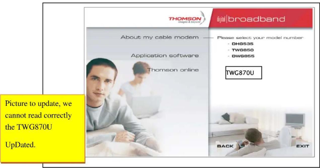
What's on the CD-ROM
Insert the Wireless Voice Gateway CD-ROM into your CD-ROM drive to view troubleshooting tips, the internal diagnostics, and other valuable information.
CD-ROM Contents:
- Electronic copy of this user's guide in additional languages (PDF format)
- Adobe Acrobat Reader — application you can load to read PDF format, if you don't have it loaded already
- Links to Thomson web site
EuroDOCSIS and EuroPacketCable are trademarks of Euro Cable Television Laboratories, Inc.
Chapter 1: Connections and Setup
Computer Requirements
For the best possible performance from your Wireless Voice Gateway, your personal computer must meet the following minimum system requirements (note that the minimum requirements may vary by cable companies):
| IBM PC COMPATIBLE | MACINTOSH** | |
| CPU | Pentium preferred | PowerPC or higher |
| System RAM | 16MB (32MB preferred) | 24MB (32MB preferred) |
| Operating System | Windows* NT / 2000 / Me / XP / Vista / Windows 7, Linux | Mac OS** 7.6.1 or higher |
| Sound Card | Required for audio on CD-ROM | N/A |
| Video | VGA or better (SVGA preferred) | VGA or better (SVGA built-in preferred) |
| CD-ROM Drive | Required | Required |
| Ethernet | 10BaseT , 100BaseT or 1000Mbps | 10BaseT , 100BaseT or 1000Mbps |
| An Ethernet card makes it possible for your computer to pass data to and from the internet. You must have an Ethernet card and software drivers installed in your computer. You will also need a standard Ethernet cable to connect the Ethernet card to your Wireless Voice Gateway. | ||
| Software | · A TCP/IP network protocol for each machine · Microsoft Internet Explorer 4.0 or later or Netscape Navigator 4.0 or later. (5.0 and 4.7 or later, respectively, are strongly recommended.) | |
- Windows is a trademark of Microsoft Corporation.
** Macintosh and the Mac OS are trademarks of Apple Computer, Inc.
Chapter 1: Connections and Setup
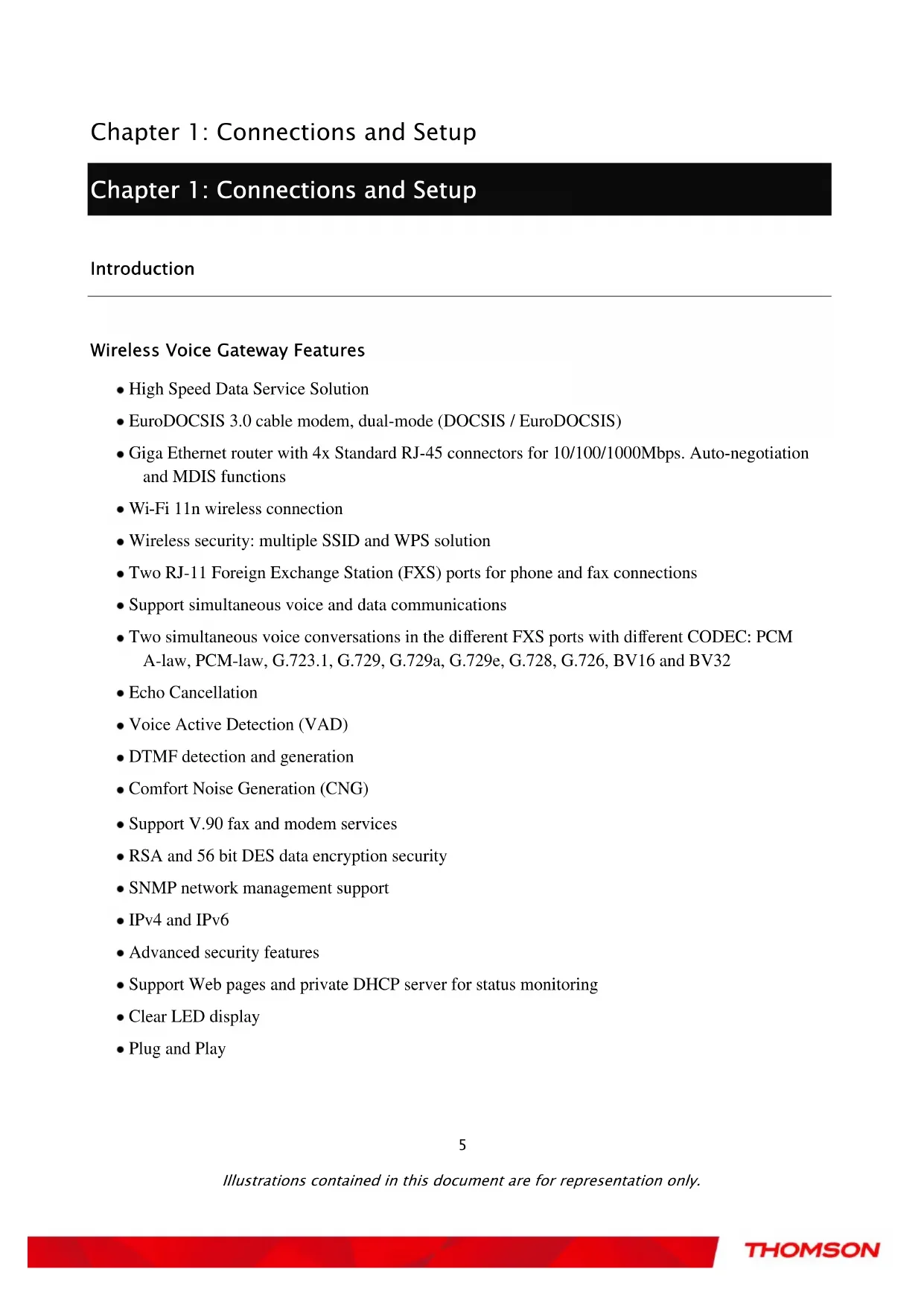
Wall Mounting
This article will show the user through the process of wall-mounting the Wireless Gateway
The Adapter has two wall-mount slots on its back panel.
Two screws are needed to mount the Adapter.

mm
To do this:
- Ensure that the wall you use is smooth, flat, dry and sturdy and use the 2 screw holes which are 101.6mm apart from each other.
- Fix the screws into wall, leaving their heads 3mm (0.12 inch) clear of the wall surface.
- Remove any connections to the unit and locate it over the screw heads. When in line, gently
Illustrations contained in this document are for representation only.
Chapter 1: Connections and Setup
push the unit on to the wall and move it downwards to secure.
Chapter 1: Connections and Setup
Wireless Voice Gateway Overview
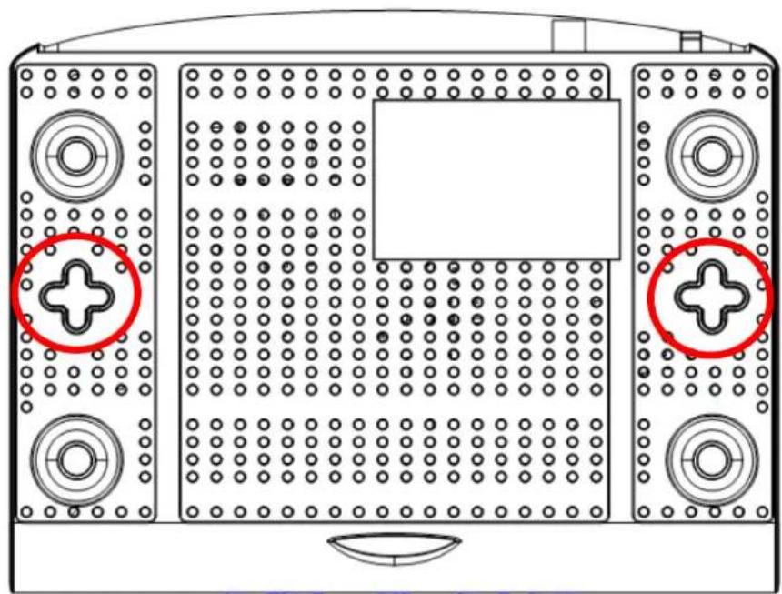
Front Panel
The following illustration shows the front panel of the Wireless Voice Gateway:
The LEDs on the front panel are described in the table below (from left to right):
| Power | Internet | Ethernet | USB | Wireless | Tel 1 | Tel 2 | Description | ||||||
| DS | US | Online | 1 | 2 | 3 | 4 | |||||||
| Boot-up Operation | ON | ON | ON | ON | ON | ON | ON | ON | ON | X | ON | ON | Power on 0.25 sec |
| ON | 0.25 second | ||||||||||||
| ON | FLASH | FLASH | FLASH | X | X | X | X | X | X | X | X | From power ON to system initialization complete | |
| ON | ON | ON | ON | X | X | X | X | X | X | X | X | Following system initialization complete to (before) DS scanning | |
| 1 second | |||||||||||||
| DOCSIS Start-up Operation | ON | FLASH | OFF | OFF | X | X | X | X | X | X | X | X | During DS scanning and acquiring SYNC |
| ON | ON | FLASH | OFF | X | X | X | X | X | X | X | X | From SYNC completed, receiving UCD to ranging completed | |
| ON | ON | ON | FLASH | X | X | X | X | X | X | X | X | During DHCP, configuration file download, registration, and Baseline Privacy Initialization: DHCP status: 1 second ON and 1 second OFF, TFTP status: 0.25 second ON and 0.25 second OFF | |
| ON | ON | ON | ON | X | X | X | X | X | X | X | X | Operational (NACO=ON) | |
| ON | FLASH | FLASH | OFF | X | X | X | X | X | X | X | X | Operational (NACO=OFF) | |
Illustrations contained in this document are for representation only.
Chapter 1: Connections and Setup
| Power | Internet | Ethernet | USB | Wireless | Tel 1 | Tel 2 | Description | ||||||
| DS | US | Online | 1 | 2 | 3 | 4 | |||||||
| Channel Bonding Operation | FLASH | FLASH | FLASH | FLASH | X | X | X | X | X | X | X | X | Wait registration with all DS and all US –Lights Flash sequentially from the right to leftMinimum duration 3 seconds |
| X | X | X | X | X | X | X | X | X | X | X | X | From 1 to 4 DS, from 1 to 4 LEDs are ON.From 5 to 8 DS, From 1 to 4 LEDs are flashingDuration 3 seconds | |
| OFF | X | X | OFF | X | X | X | X | X | X | X | X | From 1 to 2 US, from 1 to 2 LEDs are ON,from 3 to 4 US, from 1 to 2 LEDs are flashing. | |
| FLASH | FLASH | FLASH | FLASH | X | X | X | X | X | X | X | X | Wait registration with all DS and all US –Lights Flash sequentially from the left to rightMinimum duration 3 seconds | |
| MTA initialization | ON | ON | ON | ON | X | X | X | X | X | X | FLASH | OFF | MTA DHCP |
| ON | ON | ON | ON | X | X | X | X | X | X | OFF | FLASH | MTA SNMP/TFTP | |
| ON | ON | ON | ON | X | X | X | X | X | X | FLASH | FLASH | RSIP | |
| CPE Operation | ON | X | X | X | OFFONFLASH | OFFONFLASH | OFFONFLASH | OFFONFLASH | X | X | X | X | No Ethernet LinkEthernet LinkTX/RX Ethernet Traffic |
| ON | X | X | X | X | X | X | X | OFFONFLASH | X | X | X | No USB LinkUSB LinkTX/RX USB Traffic | |
| ON | X | X | X | X | X | X | X | OFFONFLASH | X | X | X | No Wireless LinkWireless LinkTX/RX Wireless Traffic | |
| MTA Operation | ON | <CM Normal Operation> | ON | ON | Both Lines On-Hook | ||||||||
| ON | FLASH | ON | Tel1 Off-hook, Tel2 On-hook | ||||||||||
| ON | ON | FLASH | Tel1 On-hook, Tel2 Off-hook | ||||||||||
| ON | FLASH | FLASH | Both Lines Off-Hook | ||||||||||
| SW Download | ON | FLASH | FLASH | ON | X | X | X | X | X | X | X | X | A software download and whileupdating the FLASH memory |
Illustrations contained in this document are for representation only.
Chapter 1: Connections and Setup

Chapter 1: Connections and Setup
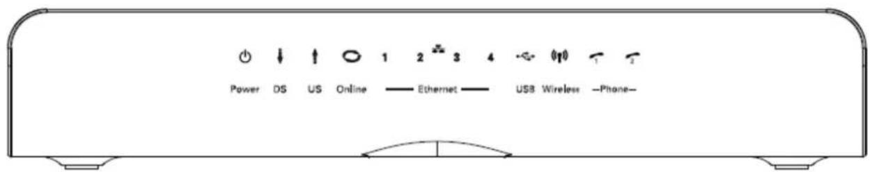
Rear Panel
A TEL1 & TEL2 2x Telephony RJ-11 connectors
B ETHERNET 1234: 4x Ethernet 10/100/1000 Mbps RJ-45 connectors
C USB Host: 1x USB 2.0 Connector
D Reset: 1x Reset or reset to factory default this Wireless Voice Gateway
E CABLE: 1xF-Connector for the coax cable
F 12VDC: 1x Power connector to connect the AC power supply
G Power switch: 1x switch to power on/off this Wireless Voice Gateway
H Antenna connectors: 2x connectors for the antennas for the Wireless interface
I WPS & WiFi on/off button: 1x button with two features: to activate/disable the WiFi, to execute a WPS association
Chapter 1: Connections and Setup
Relationship among the Devices
This illustration shows a cable company that offers Euro-DOCSIS- and Euro-PacketCable-compliant voice/data services.
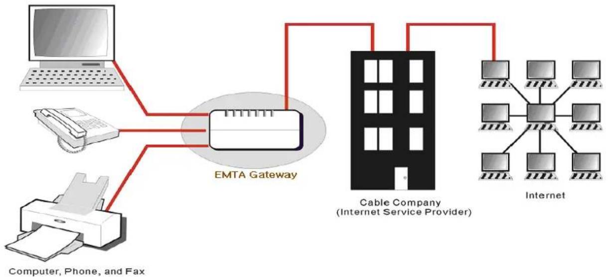
What the Modem Does
The Wireless Voice Gateway provides high-speed Internet access as well as cost-effective, toll-quality telephone voice and fax/modem services over residential, commercial, and education subscribers on public and private networks via an existing CATV infrastructure. It can inter-operate with the Euro-PacketCable compliant head-end equipment and provide the IP-based voice communications. The IP traffic can transfer between the Wireless Voice Gateway and Euro-DOCSIS compliant head-end equipment. The data security secures upstream and downstream communications.
Chapter 1: Connections and Setup
What the Modem Needs to Do Its Job
The Right Cable Company: Make sure your local cable company provides data services that use cable TV industry-standard Euro-DOCSIS compliant and Euro-PacketCable compliant technology.
The Internet/Telephony Service Provider (ISP/TSP): Your cable company provides you access to an Internet Service Provider (ISP) and Telephony Service Provider (TSP). The ISP is your gateway to the Internet and provides you with a pipeline to access Internet content on the World Wide Web (WWW). The TSP provides you with telephony access to other modems or other telephony services over the Public Switched Telephone Network (PSTN).
Check with your cable company to make sure you have everything you need to begin; they'll know if you need to install special software or re-configure your computer to make your cable internet service work for you.
Contact Your Local Cable Company
You will need to contact your cable company to establish an Internet account before you can use your gateway. You should have the following information ready (which you will find on the sticker on the gateway):
The serial number
The model number
- The Cable Modem (CM) Media Access Control (MAC) address
- The Terminal Adapter (EMTA) MAC address
- Security information: Service Set Identifier (SSID), Encryption key / passphrase (WPA2-PSK by default), channel number. Default values are indicated underneath the modem on the sticker.
Please verify the following with the cable company
The cable service to your home supports Euro-DOCSIS compliant two-way modem access.
- Your internet account has been set up. (The Media Terminal Adapter will provide data service if the cable account is set up but no telephony service is available.)
You have a cable outlet near your PC and it is ready for Cable Modem service.
Chapter 1: Connections and Setup
Note: It is important to supply power to the modem at all times. Keeping your modem plugged in will keep it connected to the Internet. This means that it will always be ready whenever you need.
Important Information
Your cable company should always be consulted before installing a new cable outlet. Do not attempt any rewiring without contacting your cable company first.
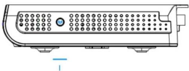
Please verify the following on the Wireless Voice Gateway
The on/off button on the rear panel must be in the ON mode = on "1"
Chapter 1: Connections and Setup
Connecting the Wireless Voice Gateway to a Single Computer
This section of the manual explains how to connect your Wireless Voice Gateway to the USB or Ethernet port on your computer and install the necessary software. Please refer to Figure 1 to help you connect your Digital Cable Modem for the best possible connection.
Attaching the Cable TV Wire to the Wireless Voice Gateway
- Locate the Cable TV wire. You may find it one of three ways:
a. Connected directly to a TV, a Cable TV converter box, or VCR. The line will be connected to the jack, which should be labeled either IN, CABLE IN, CATV, CATV IN, etc.
b. Connected to a wall-mounted cable outlet.
c. Coming out from under a baseboard heater or other location. See Figure 1 for the wiring example.
Notes: For optimum performance, be sure to connect your Wireless Voice Gateway to the first point the cable enters your home. The splitter must be rated for at least 1GHz.
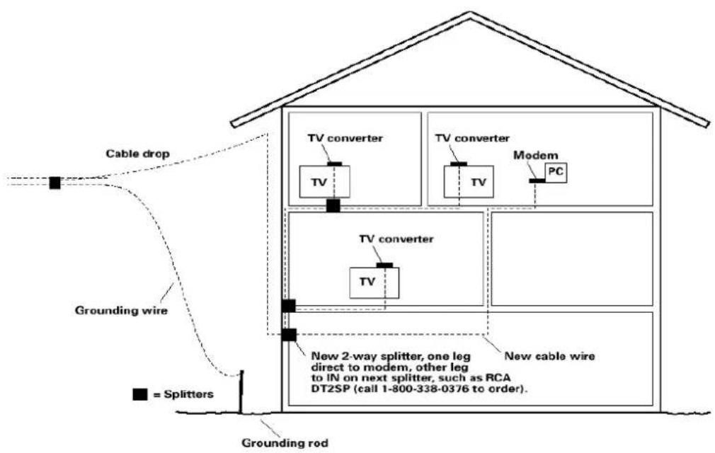
Fig.1: Basic Home Wiring
Illustrations contained in this document are for representation only.
Chapter 1: Connections and Setup
Important Connection Information
The Wireless Voice Gateway supports Ethernet and USB connections simultaneously. Below are important points to remember before you connect the Wireless Voice Gateway.
■ For Ethernet connections, go to page 15.
For telephone and fax connections, go to page 17.
If you do not want to use the CD-ROM, follow instructions 1 through 5 to connect the Wireless Voice Gateway to the USB port on your computer. Instructions must be followed in the order they appear.
- Connect one end of the coaxial cable to the cable connection on the wall, and the other end to the CABLE jack on the Wireless Voice Gateway.
- Connect the plug from the AC power supply into the POWER AC ADAPTER jack on the Wireless Voice Gateway and plug the power supply into an AC outlet.
- Insert the supplied Wireless Voice Gateway CD-ROM. Wait momentarily for the CD window display.
- Close all open applications and dialog boxes, including the CD window.
Note: Some applications may interfere with your Wireless Voice Gateway installation.
Note: Use only the power supply that accompanied this unit. Using other power supplies may damage the unit.
Chapter 1: Connections and Setup
Ethernet Connection to a Computer
Make the connection to the modem in the following sequence:
- Connect one end of the coaxial cable to the cable connection on the wall, and the other end to the CABLE jack on the Wireless Voice Gateway.
- Connect the plug from the AC power supply into the POWER AC ADAPTER jack on the Wireless Voice Gateway, and plug the power supply into an AC outlet.
Note: Use only the power supply that accompanied this unit. Using other adapters may damage the unit.
- Connect one end of the Ethernet cable to an Ethernet port on the back of your computer, and the other end to the ETHERNET port on the Wireless Voice Gateway.
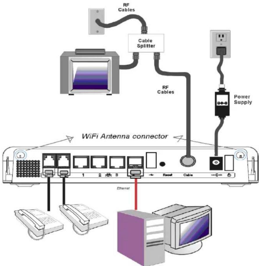
Fig.3: Ethernet Connection
Illustrations contained in this document are for representation only.
Chapter 1: Connections and Setup
Connecting More Than A Computer to the Wireless Voice Gateway
If you need to connect more than one computer to the Wireless Voice Gateway, simply connect the computers to an Ethernet port on the rear panel.
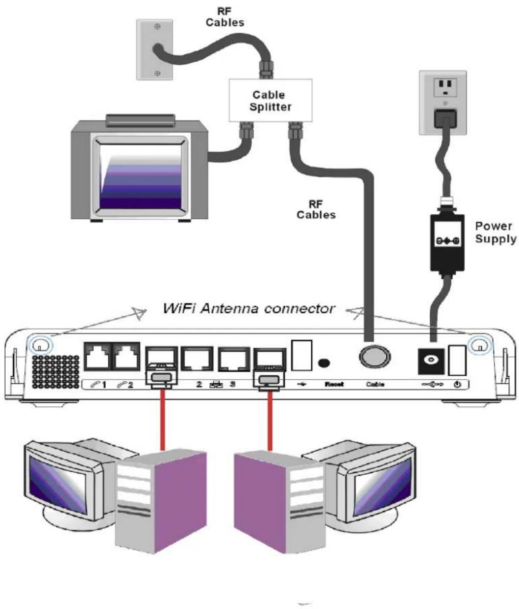
Fig.4: Multiple-PC Connection
Note: You may need to check with your service provider in order to connect multiple computers.
Illustrations contained in this document are for representation only.
Chapter 1: Connections and Setup
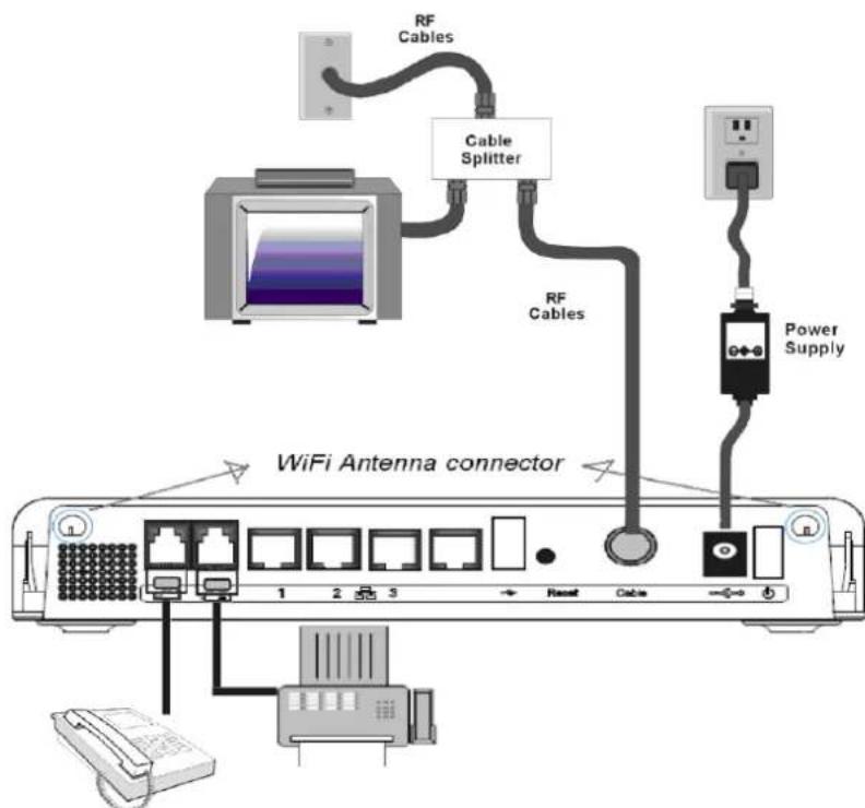
Telephone or Fax Connection
When properly connected, most telephony devices can be used with the Wireless Voice Gateway just as with a conventional telephone service. To make a normal telephone call, pick up the handset; listen for a dial tone, then dial the desired number. For services such as call waiting, use the hook switch (or FLASH button) to change calls. The following procedures describe some of the possible connection schemes for using telephony devices with the Wireless Voice Gateway.
-
Connect a standard phone line cord directly from the phone (fax machine, answering machine, caller ID box, etc.) to one of the LINE jacks on the Wireless Voice Gateway.
-
If there is a phone line in your home which is NOT connected to another telephone service provider, connect a standard phone line cord from a jack on this line to one of the LINE jacks of the Wireless Voice Gateway. Connect a standard phone line cord directly from the phone (fax machine, answering machine, caller ID box, etc.) to one of the other jacks in the house that uses that line.
-
If you have a multi-line telephone, connect a standard phone line cord (not an RJ-14 type line cord) from the phone to the LINE jacks on the Wireless Voice Gateway. (Other phones can be added to each line by using standard phone line splitters.
Illustrations contained in this document are for representation only.
Chapter 1: Connections and Setup
Fig. 5: Phone/Fax Connection
Turning on the Wireless Voice Gateway
If there is no lighted LEDs on the front panel, check the power on/off switch position on the back panel of Wireless Gateway: it must be "ON" = "1".
After installing the Wireless Voice Gateway and turn it on for the first time (and each time the modem is reconnected to the power), it goes through several steps before it can be used. Each of these steps is represented by a different pattern of flashing lights on the front of the modem.
Note: All indicators flash once before the initialization sequence.
If both DS and US LEDs are flashing sequentially, it means the Wireless Voice Gateway is automatically updating its system software. Please wait for the lights to stop flashing. You cannot use your modem during this time. Do not remove the power supply, switch off (on/off switch) or reset the Wireless Voice Gateway during this process.
Chapter 2: WEB Configuration
To make sure that you can access the Internet successfully, please check the following first.
- Make sure the connection (through Ethernet or USB) between the Wireless Voice Gateway and your computer is OK.
- Make sure the TCP/IP protocol is set properly.
- Subscribe to a Cable Company.
Accessing the Web Configuration
The Wireless Voice Gateway offers local management capability through a built in HTTP server and a number of diagnostic and configuration web pages. You can configure the settings on the web page and apply them to the device.
Once your host PC is properly configured; please proceed as follows:
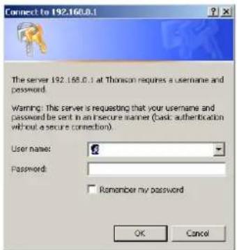
- Start your web browser and type the private IP address of the Wireless Voice Gateway on the URL field: 192.168.0.1.
- After connecting to the device, you will be prompted to enter username and password. By default, the username is “” (empty) and the password is “admin”.
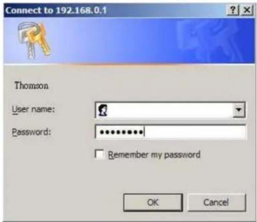
Fig. 6
If you login successfully, the main page will appear.
Chapter 2: WEB Configuration
Outline of Web Manager
The main screen will be shown as below.
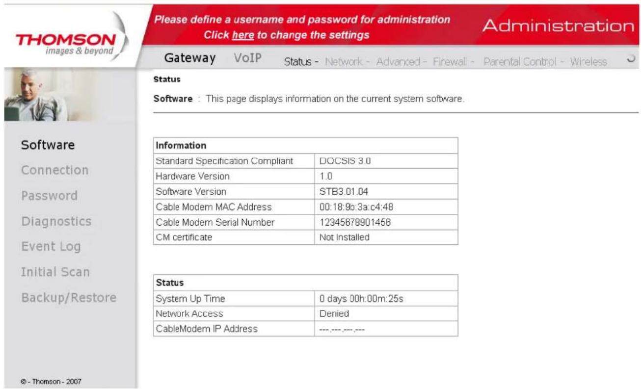
Fig. 7
- Main Menu: the hyperlinks on the top of the page, including Gateway, VoIP and several sub-menu items
- Title: the sidebar on the left side of the page indicates the title of this management interface, e.g., Software in this example
- Main Window: the current workspace of the web management, containing configuration or status information
For easy navigation, the pages are organized in groups with group in names main menu. Individual page names within each group are provided in the sidebar. So to navigate to a page, click the group hyperlink at the top, then the page title on the sidebar.
Your cable company may not support the reporting of some items of information listed on your gateway's internal web pages. In such cases, the information field appears blank. This is normal.
Chapter 2: WEB Configuration
Warning message to change the password
At your first connection or while the password is the default one, a warning message is displayed on the top banner of each Web configuration page. We want to encourage you to change the password in order to enforce the security of your modem. Please refer to the chapter "Password" page 28 for more information.
Gateway - Status Web Page Group
1. Software
The information section shows the hardware and software information about your gateway.
The status section of this page shows how long your gateway has operated since last time being powered up, and some key information the Cable Modem received during the initialization process with your cable company. If Network Access shows "Allowed," then your cable company has configured your gateway to have Internet connectivity. If not, you may not have Internet access, and should contact your cable company to resolve this.
THOMSON
images & beyond
Please define a username and password for administration
Click here to change the settings
Administration
Gateway
VoIP
Status
Network - Advanced - Firewall
Parental Control - Wireless
Status
Password : This page allows configuration of administration access privileges and the ability to restore factory defaults to the system.
Software
Connection
Password
Diagnostics
Event Log
Initial Scan
Backup/Restore
© - Thomson - 2007
UserID
Password
Re-Enter Password
V
Chapter 2: WEB Configuration
2. Connection
This page reports current connection status containing startup procedures, downstream and upstream status, CM online information, and so on. The information can be useful to your cable company's support technician if you're having problems.
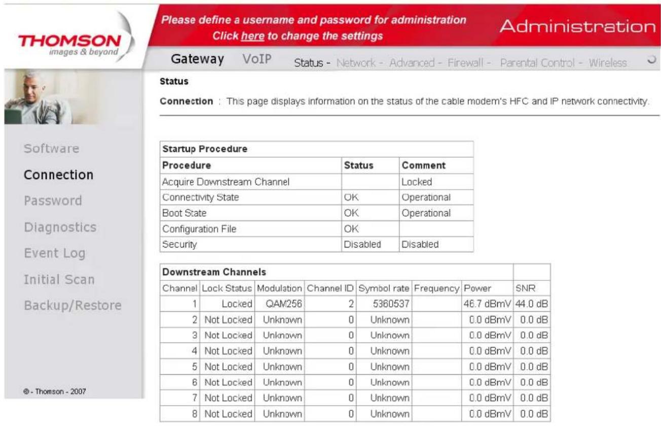
Fig. 8
| Upstream Channels | ||||||
| Channel | Lock Status | Modulation | Channel ID | Symbol Rate | Frequency | Power |
| 1 | Locked | QAM84 | 2 | 2560 Ksym/sec | 37.5 dBmV | |
| 2 | Not Locked | Unknown | 0 | 0 Ksym/sec | 0.0 dBmV | |
| 3 | Not Locked | Unknown | 0 | 0 Ksym/sec | 0.0 dBmV | |
| 4 | Not Locked | Unknown | 0 | 0 Ksym/sec | 0.0 dBmV | |
| CM IP Address | Duration | Expires |
| -------- | D:--H:--M:M--S::-- | -------- |
Current System Time: Tue Dec 15 09:58:41 2009
Illustrations contained in this document are for representation only.
Chapter 2: WEB Configuration
Fig. 9
3. Password
Forcing end user to change the password
Upon access to the web pages on the CPE side of the router, if the user has not changed the default web password, a warning message must be displayed in the top banner of the web interface such as being visible while accessing any tabs.
This warning message informs the user that the default password must be changed:
Please define a username and password for administration Click here to change the settings
Administration
In the
second sentence, "here" is a hyperlink to the password setting page. Clicking on "here" lead to the display of the password setting page.
More information
By default, the username is empty ("") and the password is "admin".
This is set by different actions (non exhaustive list):
- at the manufactory level,
- following a reset factory on the modem,
- following a reset from the operator,
- following a change by the user who wants to come back to the default setting after using its own settings
When the current password is the default one, the user is strongly encouraged to change the default web password:
- Once the user logs in the web pages, the password setting page is displayed
- the warning message must be displayed in the top banner of the web interface
- The user can still access to all the web pages even if the password is not changed
- The warning message must be displayed on the top banner of each accessed Web page while the password is not changed
- The password warning message must be visible while accessing all tabs in a the same web page
Chapter 2: WEB Configuration
- The password warning message is no more displayed on the banners once the default password has been replaced by a new one.
At your first connection or while the password is the default one, a warning message is displayed on the top banner of each Web configuration page. We want to encourage you to change the password in order to enforce the security of your modem.
The password can be a maximum of 8 characters and is case sensitive. In addition, this page can be used to restore the gateway to its original factory settings. Use this with caution, as all the settings you have made will be lost. To perform this reset, set Restore Factory Defaults to Yes and click Apply. This has the same effect as a factory reset using the rear panel reset switch, where you hold on the switch for 15 seconds, then release it.
Note: We are always suggesting to modify the password is implementing for Voice Wireless Gateway.
It is a basically protection to access Voice Wireless Gateway.
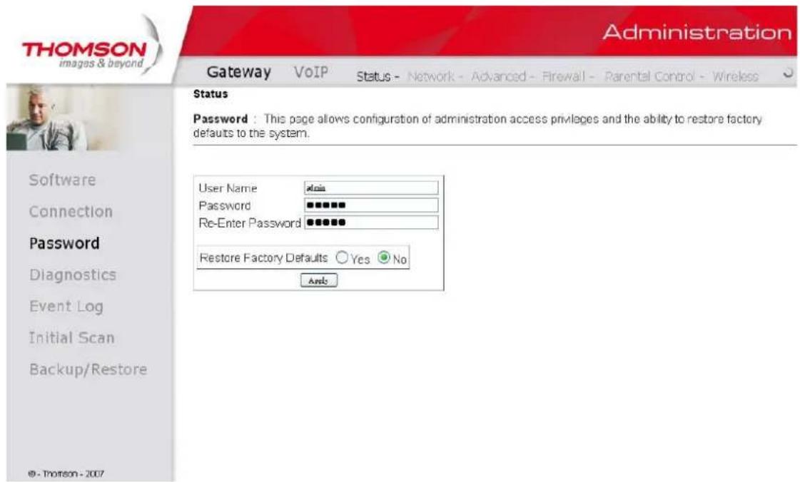
Fig. 10
To change the password: type the password, and re-enter it again.
If the password is accepted, you are required to re log on the web pages:
Chapter 2: WEB Configuration
If the password is no accepted, an error message is displayed:
Error converting one or more entries:
Password confirmation failure
TRY AGAIN
Click on try again.
4. Diagnostics
This page offers basic diagnostic tools for you to utilize when connectivity problems occur. When you ping an Internet device, you send a packet to its TCP/IP stack, and it sends one back to yours. To use the ping Test, enter the information needed and press Start Test; the Result will be displayed in the lower part of the window. Press Abort Test to stop, and Clear Results to clear the result contents.
Note: Firewalls may cause pings to fail but still provide you TCP/IP access to selected devices behind them. Keep this in mind when pinging a device that may be behind a firewall. Ping is most useful to verify connectivity with PCs which do not have firewalls, such as the PCs on your LAN side.
Chapter 2: WEB Configuration
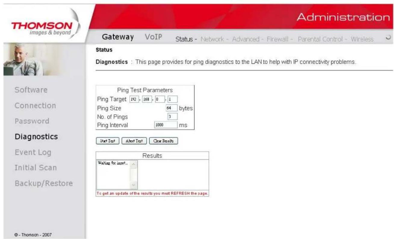
Fig. 11
5.Event Log
This page displays the contents of the SNMP event log. Press "Clear Log" button to clear the logs.
Illustrations contained in this document are for representation only.
Chapter 2: WEB Configuration
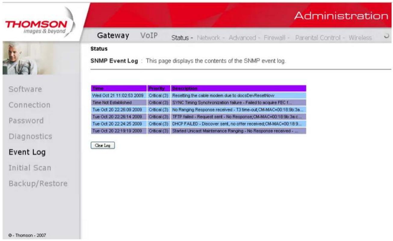
Fig. 12
6. Initial Scan
To speed up the modem's first time startup, enter known downstream frequency and/or upstream channel ID information here. Then click "Apply and Reboot" button to start scanning the cable network beginning with the values supplied here.
The value is provided in Hertz. So for 562MHz , you must type: 562000000
Illustrations contained in this document are for representation only.
Chapter 2: WEB Configuration
Fig. 13
7 Backup/Restore
Backup/Restore Settings : This page allows you to save your current settings locally on your PC, or restored settings previously saved. The file name is "GatewaySettings.bin".
Fig 14
33
Illustrations contained in this document are for representation only.
1. LAN
You can activate the DHCP server function for the LAN on this page.
With this activated function,
- your cable company's DHCP server provides one IP address for your gateway,
- and your gateway's DHCP server provides IP addresses, starting at the address you set in IP Address on the LAN page, to your PCs. A DHCP server leases an IP address with an expiration time.
To change the lowest IP address that your gateway will issue to your PCs, enter it into the IP Address box and then click Apply.
IP Address and Subnet Mask:
A private IP address and Subnet Mask for LAN sub netting.
For example 192.168.0.1./255.255.255.0.
DHCP Server:
- Select the check point of "Yes" or "No" to enable or disable a simple DHCP server for LAN.
- Configure the IP address numbers for the DHCP server with "lease pool start" and "lease pool end".
- Configure the IP address lease time with "lease time" for DHCP server. Default value is 604800 seconds.
Chapter 2: WEB Configuration
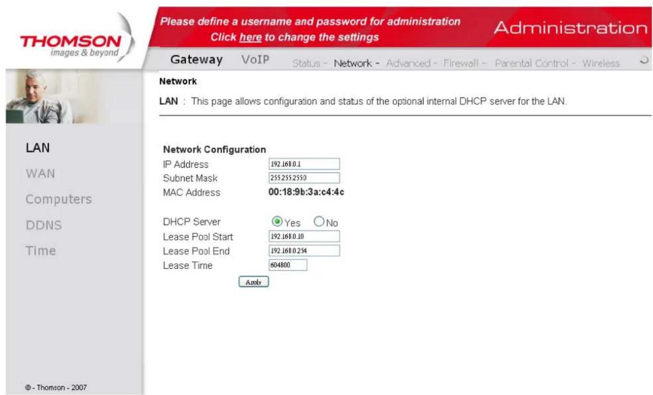
Fig. 15
2. WAN
You can configure the optional internal DHCP server for the WAN on this page. This can be required by some ISP providers.
Select different WAN Connection Type will lead to different contents. Take the WAN connection type-DHCP for example, you can release and renew the WAN lease by pressing the buttons.
You can enter a spoofed MAC address that causes your gateway networking stack to use that MAC address when communicating instead of the usual WAN MAC address, e.g., if the MAC address is 00:11:e3:df:66:95, this spoofed MAC address could be 00:11:e3:df:66:97 or any desired MAC address.
Chapter 2: WEB Configuration
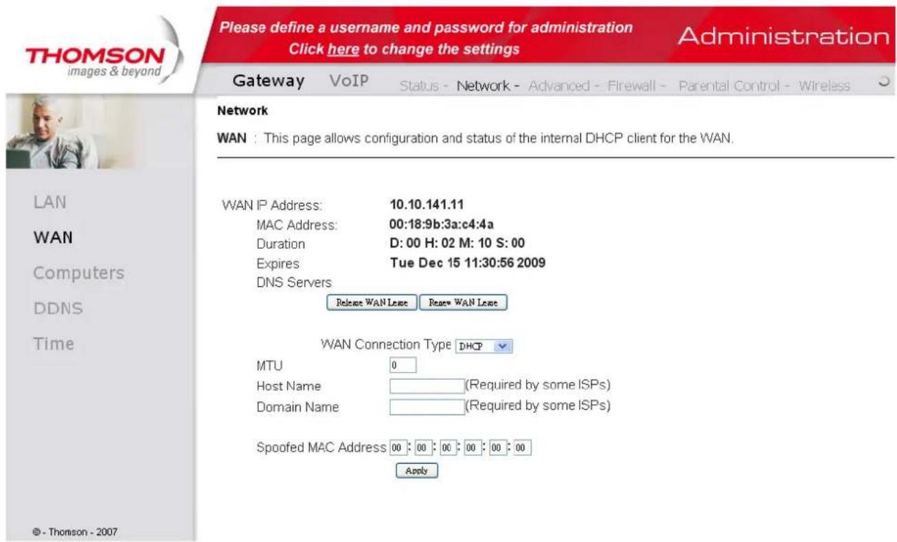
Fig. 16
Illustrations contained in this document are for representation only.
Chapter 2: WEB Configuration
3. Computers
This page displays the status of the DHCP clients and current system time. You can cancel an IP address lease by selecting it in the DHCP Client Lease Info list and then clicking the Force Available button. If you do so, you may have to perform a DHCP Renew on that PC, so that it can obtain a new lease.
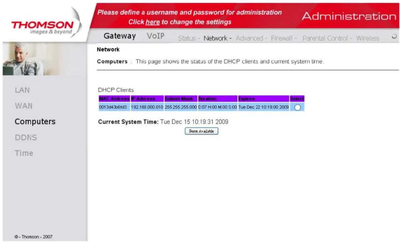
Fig. 17
Illustrations contained in this document are for representation only.
Chapter 2: WEB Configuration
4. DDNS - Dynamic DNS service
This page allows to setup for Dynamic DNS server.
Fig 18
Chapter 2: WEB Configuration
5. Time server
This page allows configuration and display of the system time obtained from network servers via Simple Network Time Protocol. The system has to be reset for any changes to take effect.
Fig 19
Chapter 2: WEB Configuration
Gateway - Advanced Web Page Group
1. Options
This page allows you to enable/disable some features of the Wireless Voice Gateway.
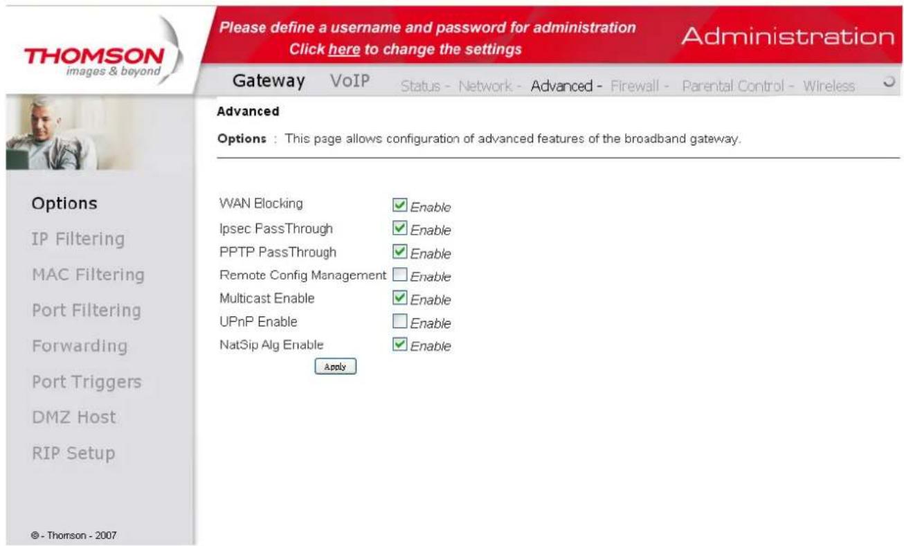
Fig. 20
- WAN Blocking prevents others on the WAN side from being able to ping your gateway. With WAN Blocking enabled, your gateway will not respond to pings it receives, effectively "hiding" your gateway.
- Ipsec PassThrough enables IpSec type packets to pass WAN LAN. IpSec (IP Security) is a security mechanism used in Virtual Private Networks (VPNs).
- PPTP PassThrough enables PPTP type packets to pass WAN LAN. PPTP (Point to Point Tunneling Protocol) is another mechanism sometimes used in VPNs.
- Remote Config Management makes the configuration web pages in your gateway accessible from the WAN side. Note that page access is limited to only those who know the gateway access password. When accessing your gateway from a remote location, your must use HTTP port 8080
Illustrations contained in this document are for representation only.
Chapter 2: WEB Configuration
and the WAN IP address of the gateway. For example, if the WAN IP address is 157.254.5.7, you would navigate to http://157.254.5.7:8080 to reach your gateway.
- Multicast Enable enables multicast traffic to pass WAN LAN. You may need to enable this to see some types of broadcast streaming and content on the Internet.
- UPnP Universal Plug and Play (UPnP) helps devices, such as Internet appliances and computers, access the network and connect to other devices as needed. UPnP devices can automatically discover the services from other registered UPnP devices on the network.
- NatSipAlg Enable the gateway implements SIP ALG (Application-level gateway). It is enabled by default and help in solving NAT related problems in client LAN side.
2. IP Filtering
This page enables you to enter the IP address ranges of PCs on your LAN that you don't want to have outbound access to the WAN. These PCs can still communicate with each other on your LAN, but packets designated to WAN addresses are blocked by the gateway.
Fig. 18
3. MAC Filtering
This page enables you to enter the MAC address of specific PCs on your LAN that you do not wish to have outbound access to the WAN. As with IP filtering, these PCs can still communicate with each other through the gateway, but packets they send to WAN addresses are blocked.
Chapter 2: WEB Configuration
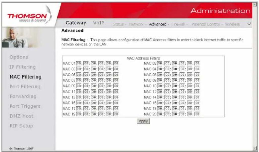
Fig. 19
4. Port Filtering
This page allows you to enter ranges of destination ports (applications) that you don't want your LAN PCs to send packets to. Any packets your LAN PCs send to these destination ports will be blocked. For example, you could block access to worldwide web browsing (http = port 80) but still allow email service (SMTP port 25 and POP-3 port 110). To enable port filtering, set Start Port and End Port for each range, and click Apply. To block only one port, set both Start and End ports with the same value.
Illustrations contained in this document are for representation only.
Chapter 2: WEB Configuration
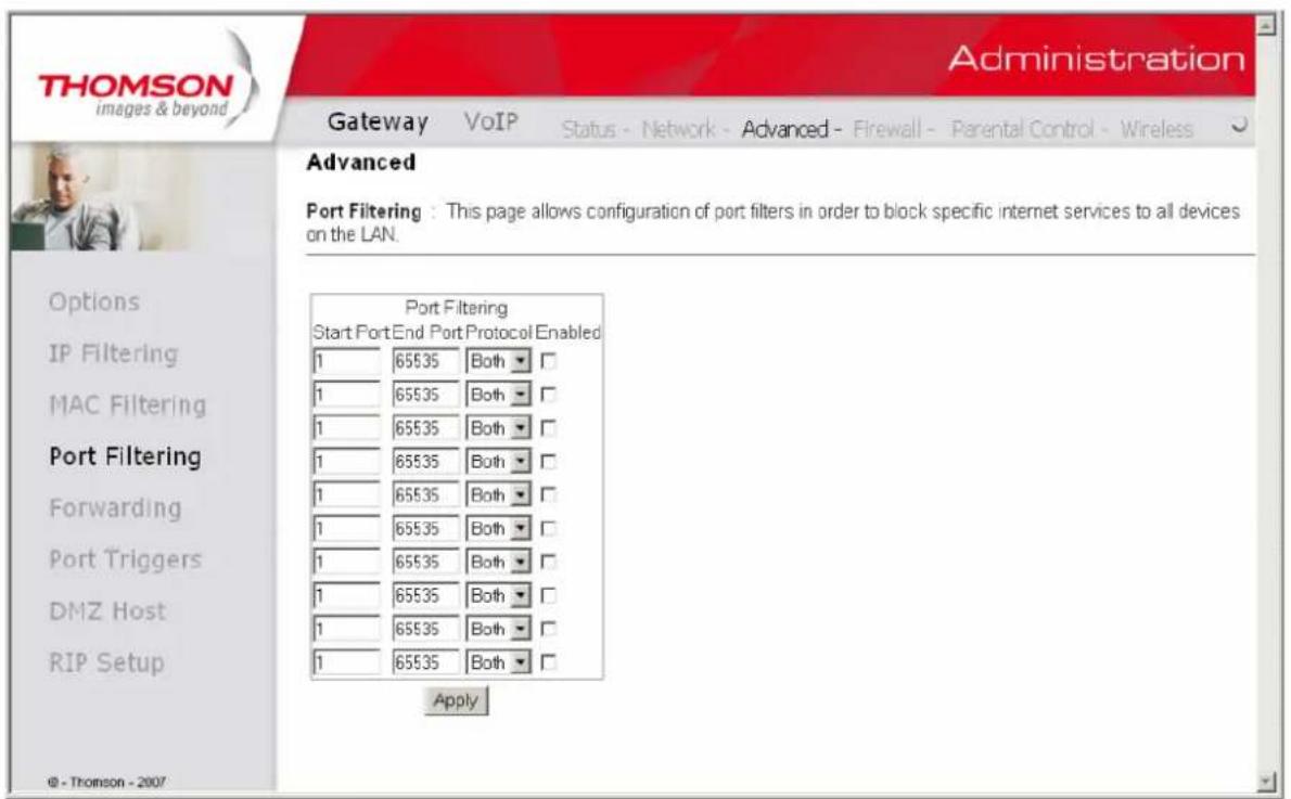
Fig. 20
5. Forwarding
For LAN WAN communications, the gateway normally only allows you to originate an IP connection with a PC on the WAN; it will ignore attempts of the WAN PC to originate a connection onto your PC. This protects you from malicious attacks from outsiders. However, sometimes you may wish for anyone outside to be able to originate a connection to a particular PC on your LAN if the destination port (application) matches one you specify.
This page allows you to specify up to 10 such rules. For example, to specify that outsiders should have access to an FTP server you have running at 192.168.0.5, create a rule with that address and Start Port =20 and End Port =21 (FTP port ranges) and Protocol = TCP (FTP runs over TCP and the other transport protocol, UDP), and click Apply. This will cause inbound packets that match to be forwarded to that PC rather than blocked. As these connections are not tracked, no entry is made for them in the Connection Table. The same IP address can be entered multiple times with different ports.
Chapter 2: WEB Configuration
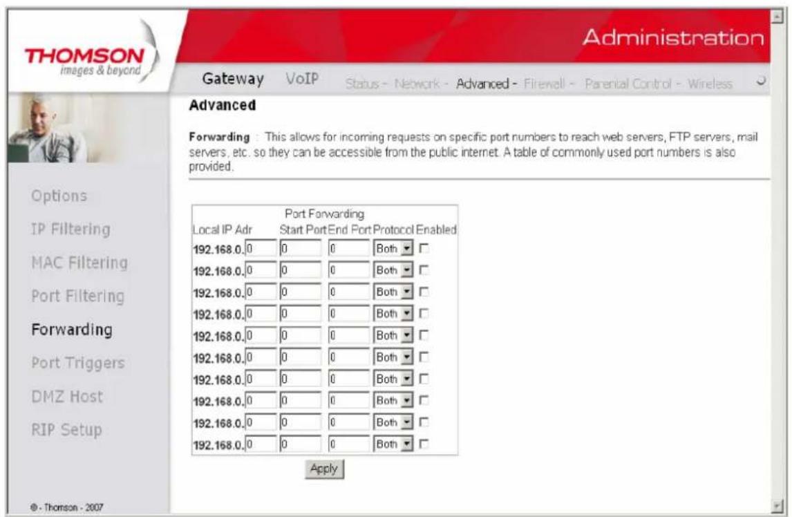
Fig. 21
6. Port Triggers
Some Internet activities, such as interactive gaming, require that a PC on the WAN side of your gateway be able to originate connections during the game with your game playing PC on the LAN side. You could use the Advanced-Forwarding web page to construct a forwarding rule during the game, and then remove it afterwards (to restore full protection to your LAN PC) to facilitate this. Port triggering is an elegant mechanism that does this work for you, each time you play the game.
Illustrations contained in this document are for representation only.
Chapter 2: WEB Configuration
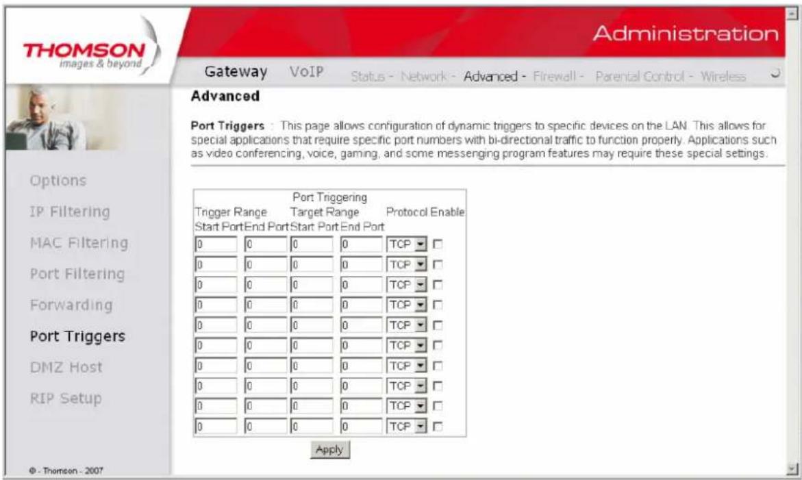
Fig. 22
Port Triggering works as follows. Imagine you want to play a particular game with PCs somewhere on the Internet. You make one time effort to set up a Port Trigger for that game, by entering into Trigger Range the range of destination ports your game will be sending to, and entering into Target Range the range of destination ports the other player (on the WAN side) will be sending to (ports your PC's game receives on). Application programs like games publish this information in user manuals. Later, each time you play the game, the gateway automatically creates the forwarding rule necessary. This rule is valid until 10 minutes after it sees game activity stop. After 10 minutes, the rule becomes inactive until the next matched outgoing traffic arrives.
For example, suppose you specify Trigger Range from 6660 to 6670 and Target Range from 113 to 113. An outbound packet arrives at the gateway with your game-playing PC source IP address 192.168.0.10, destination port 666 over TCP/IP. This destination port is within the Trigger destined for port 113 to your game-playing PC at 192.168.0.10.
You can specify up to 10 port ranges on which to trigger.
Illustrations contained in this document are for representation only.
Chapter 2: WEB Configuration
7. DMZ Host
Use this page to designate one PC on your LAN that should be left accessible to all PCs from the WAN side, for all ports. For example, if you put an HTTP server on this machine, anyone will be able to access that HTTP server by using your gateway IP address as the destination. A setting of -0| indicates NO DMZ PC. —Host is another Internet term for a PC connected to the Internet.
Fig. 23
8. RIP (Routing Information Protocol) Setup
This feature enables the gateway to be used in small business situations where more than one LAN (local area network) is installed. The RIP protocol provides the gateway a means to—advertise| available IP routes to these LANs to your cable operator, so packets can be routed properly in this situation.
Your cable operator will advise you during installation if any setting changes are required here.
Chapter 2: WEB Configuration
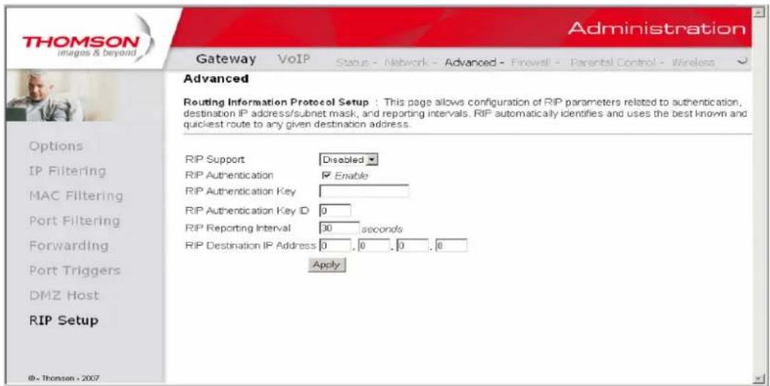
Fig. 24
Illustrations contained in this document are for representation only.
Chapter 2: WEB Configuration
Gateway - Firewall Web Page Group
1. Web Content Filtering
These pages allow you to enable, disable, and configure a variety of firewall features associated with web browsing, which uses the HTTP protocol and transports HTML web pages. On these pages, you designate the gateway packet types you want to have forwarded or blocked. You can activate settings by checking them and clicking Apply.
The web-related filtering features you can activate from the Web Content Filter page include Filter Proxy, Filter Cookies, Filter Java Applets, Filter ActiveX, Filter Popup Windows, and Firewall Protection.
If you want the gateway to exclude your selected filters to certain computers on your LAN, enter their MAC addresses in the Trusted Computers area of this page.
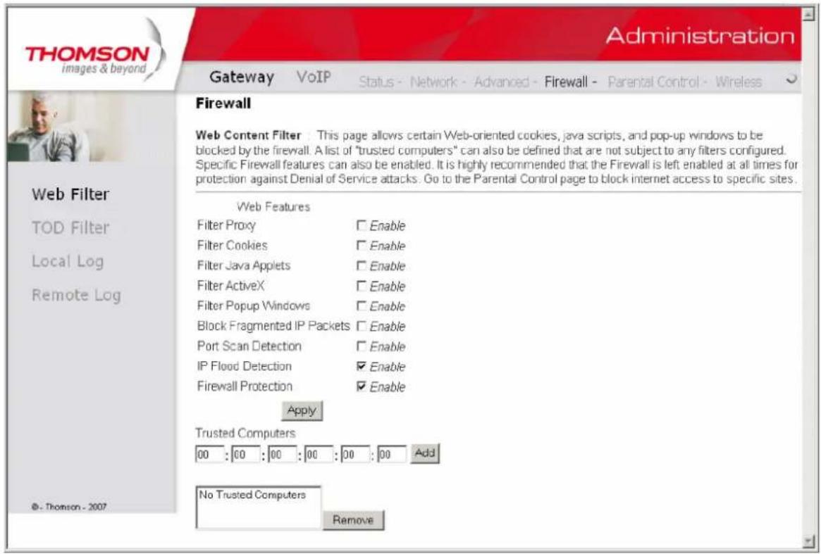
Fig. 25
Illustrations contained in this document are for representation only.
Chapter 2: WEB Configuration
2. TOD Filtering
Use this page to set rules that will block specific LAN side PCs from accessing the Internet, but only at specific days and times. Specify a PC by its hardware MAC address, and then use the tools to specify blocking time. Finally, click the Apply button to save your settings.
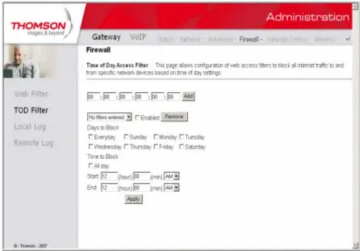
Fig. 26
Illustrations contained in this document are for representation only.
Chapter 2: WEB Configuration
3. Local Log and Remote Log
The gateway builds a log of firewall blocking actions that Firewall has taken.Using the Local Log page lets you specify an email address to which you want the gateway to email this log. You must also tell the gateway your outgoing (i.e. SMTP) email server's name, so it can direct the email to it. Enable Email Alerts has the gateway forward email notices when Firewall protection events occur. Click E-mail Log to immediately send the email log. Click Clear Log to clear the table of entries for a fresh start.
The log of these events is also visible on the screen. For each blocking event type that has taken place since the table was last cleared, the table shows Description, Count, Last Occurrence, Target, and Source.
Fig. 27
The Remote Log page allows you to specify the IP address where a SysLog server is located and select different types of firewall events that may occur. Then, each time such an event occurs, notification is automatically sent to this log server.
Chapter 2: WEB Configuration
Fig. 28
Gateway - Parental Control Web Page Group
1. Basic
This page allows you to enable, disable, and configure a variety of firewall features associated with web browsing, which uses the HTTP protocol and transports HTML web pages. On these pages, you designate the gateway packet types you want to have forwarded or blocked. You can activate settings by checking them and clicking Apply.
Here are some of your choices on the Parental Control page:
Activate Keyword Blocking and specify some keywords in the Keyword List to cause blocking of web pages on the WAN side with the specified keyword in the content.
Activate Domain Blocking and specify some Domain Names (e.g. disney.com) in the Domain List.
Chapter 2: WEB Configuration
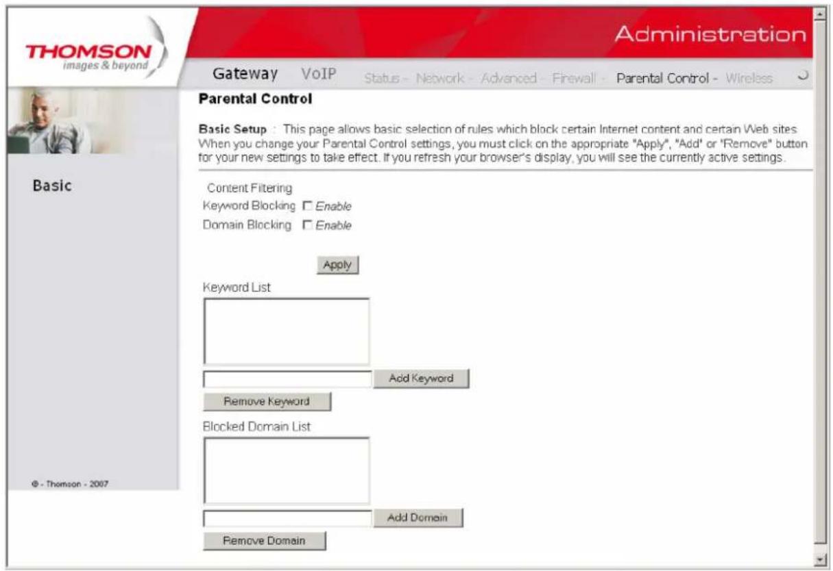
Fig. 29
Illustrations contained in this document are for representation only.
Important: Changes to the wireless web pages should be made from a PC that is hard
wired to the gateway, i.e. via Ethernet.
The Wireless web pages group enables a variety of settings that can provide secure and reliable wireless communications for even the most demanding tech-savvy user.
The Wireless Voice Gateway offers a choice of 802.1x, WPA and WPA-PSK authentication of your PCs to the gateway, 64 and 128 bit WEP encryption of communication between the gateway and your PCs to guaranty security, and an Access Control List function that enables you to restrict wireless access to only your specific PCs.
The wireless function will probably work in your home as shipped from the factory, but without the security features activated. In addition, the factory default wireless channel setting may not provide optimum changes are recommended from the factory defaults, to secure your wireless communications and provide optimum performance.
Performance
Because your wireless communication travels through the air, the factory default wireless channel setting may not provide optimum performance in your home if you or your neighbors have other interfering 2.4GHz devices such as cordless phones. If your wireless PC is experiencing very sluggish or dramatically slower communication compared with the speed you achieve on your PC that is wired to the gateway, try changing the channel number. See the 802.11b/g Basic Web Page discussion below for details.
Authentication
Authentication enables you to restrict your gateway from communicating with any remote wireless PCs that aren't yours. The following minimum authentication-related changes to factory defaults are recommended. See the 802.11b/g Basic and Access Control Web Page discussions below for details.
Network Name (SSID) - Set a unique name you choose
Network Type - Set to Open
Access Control List - Enter your wireless PCs' MAC addresses
Chapter 2: WEB Configuration
Security
Security secures or scrambles messages traveling through the air between your wireless PCs and the gateway, so they can't be observed by others. The following minimum security setting changes to factory defaults are recommended. See the 802.11b/g Security Web Page discussion below for details.
Data Encryption - Set to WEP (64-bit)
PassPhrase - Use this feature to generate security keys
1. 802.11b/g/n Radio
To set the basic configuration for the wireless features, click RADIO from the Wireless menu. These must match the settings you make on your wireless-equipped PC on the LAN side.
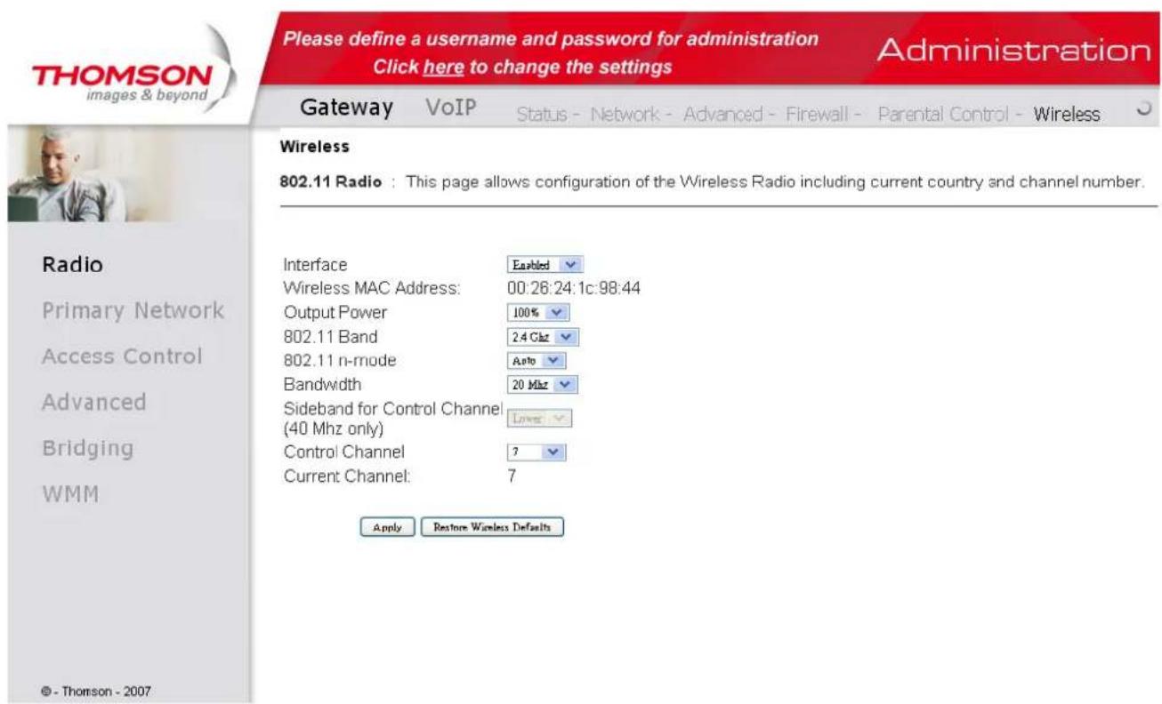
Fig. 30
Chapter 2: WEB Configuration
Table1. Basic Settings Definitions
| Setting | Description | Value List or Range | Default |
| Network Name (SSID) | Set the Network Name (also known asSSID) of this network. | Up to 32-character string containing ASCII characters with codes between 0x20 and 0x7e | UPCxxxxxx |
| Network Type | Select Closed to hide the network from active scans. Select Open to reveal the network to active scans. | Open, Closed | Open |
| New Channel | Select a particular channel on which to operate. | 1-13 | 1, 7 or 11 |
| Interface | Enable or disable the wireless interface. | Enabled, Disabled | Enabled |
2.802.11b/g/n Security - Primary Network
This page allows you to configure the Network Authentication. It provides several different modes of wireless security. You will have to enter proper information according to the mode you select.
Chapter 2: WEB Configuration
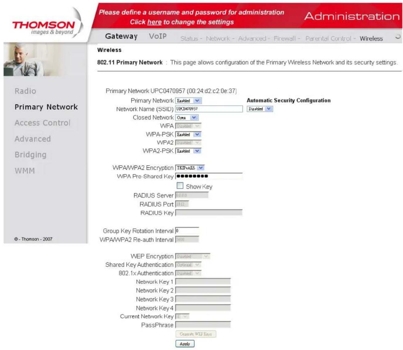
Fig. 31
WPA (Wi-Fi Protected Access)/WPA2:
It must be used in conjunction with an authentication server such as RADIUS to provide centralized access control and management. It can provide stronger encryption and authentication solution than none WPA modes. WPA2 is the second generation of WPA security
WPA-PSK (WPA-Pre-Shared Key) /WPA2-PSK (WPA2-Pre-Shared Key):
It is useful for small places without authentication servers such as the network at home. It allows the use of manually-entered keys or passwords and is designed to be easily set up for home users.
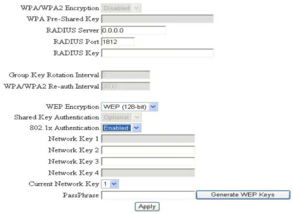
WEP Encryption:
Illustrations contained in this document are for representation only.
Chapter 2: WEB Configuration
You can choose 64-bit or 128-bit according to your needs. If you choose Disabled, the Network Keys will not be shown on this page. If selected, the data is encrypted using the key before being transmitted. For example, if you set 128-bit in this field, then the receiving station must be set to use the 128 Bit Encryption, and have the same Key value too. Otherwise, it will not be able to decrypt the data. (Note: You need to connect one end of the Ethernet cable to the Ethernet port on the back of your computer, and the other end to the ETHERNET port on the Wireless Voice Gateway.)
- If you select WEP (64-bit or 128-bit), you can adjust the following settings
- Shared Key Authentication: Decide whether to set the shared key Optional or Required by selecting from the drop-down menu.
- Network Key 1 to 4: The system allows you to enter four sets of the WEP key. For 64-bit WEP mode, the key length is 5 characters or 10 hexadecimal digits. As for 128-bit WEP mode, the key length is 13 characters or 26 hexadecimal digits.
- Current Network Key : Select one set of the network key (from 1 to 4) as the default one.
- PassPhrase : You can enter ASCII codes into this field. The range is from 8 characters to 64 characters. For ASCII characters, you can key in 63 characters in this field. If you want to key in 64 characters, only hexadecimal characters can be used.
- Generate WEP Keys : Click this button to generate the PassPhrase.
Fig. 32
- Apply: After proper configuration, click Apply to invoke the settings.
802.1x Authentication
If you enable the 802.1x authentication function, you will have to offer the following information-
- RADIUS Server: RADIUS Server is a protocol for carrying authentication, authorization, and configuration information between a Network Access Server which desires to authenticate its links and a shared Authentication Server. Please key in the IP Address for the RADIUS Server.
- RADIUS Port : Besides the IP address of the RADIUS Server, you have to enter the port number for the server. Port 1812 is the reserved RADIUS-authentication port described in RFC 2138.
Chapter 2: WEB Configuration
Earlier AP (RADIUS clients) use port 1945. The default value will be shown on this box. You can keep and use it.
- RADIUS Key: A RADIUS Key is like a password, which is used between IAS and the specific RADIUS client to verify identity. Both IAS and the RADIUS client must be use the same RADIUS Key for successful communication to occur. Enter the RADIUS Key.
WPA/WPA2
For the WPA/WPA2 network Authentication, the settings that you can adjust including WPA/WPA2 Encryption, RADIUS Server, RADIUS Port, RADIUS Key, Group Key Rotation Interval, and WPA/WPA2 Re-auth Interval.
WPA/WPA2 Encryption : There are three types that you can choose, TKIP, AES*, TKIP+AES.
TKIP takes the original master key only as a starting point and derives its encryption keys mathematically from this mater key. Then it regularly changes and rotates the encryption keys so that the same encryption key will never be used twice
** AES provides security between client workstations operating in ad hoc mode. It uses a mathematical ciphering algorithm that employs variable key sizes of 128, 192 or 256 bits.
Chapter 2: WEB Configuration
- RADIUS Server/RADIUS Port/RADIUS Key : Please refer to the previous page.
- Group Key Rotation Interval : Key in the time for the WAP group key rotation interval. The unit is second. With increasing rekey interval, user bandwidth requirement is reduced.
- WPA/WPA2 Re-auth Interval : When a wireless client has associated with the Wireless Voice Gateway for a period of time longer than the setting here, it would be disconnected and the authentication will be executed again. The default value is 3600, you may modify it.
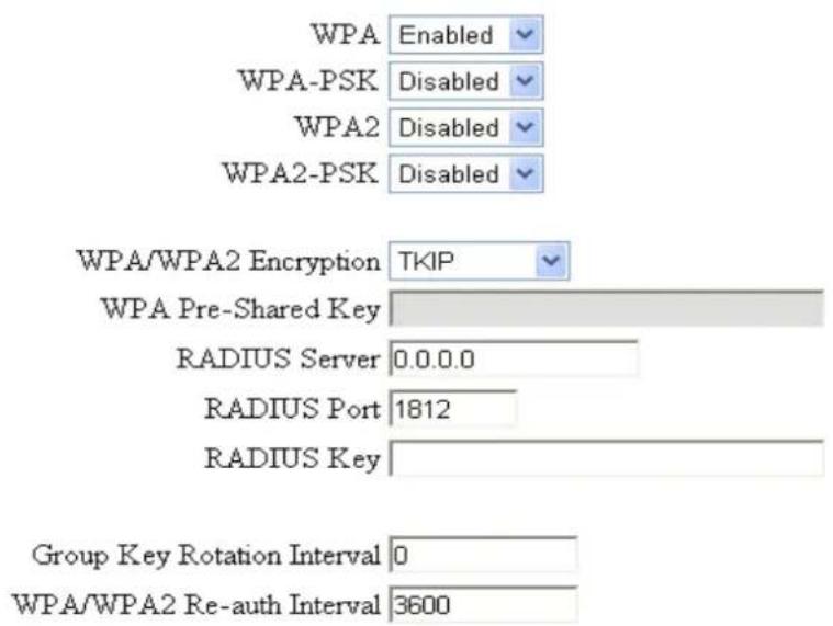
Fig. 34
WPA-PSK/WPA2-PSK
For the WPA-PSK/WPA2-PSK network Authentication, the settings that you can adjust including WPA/WPA2 Encryption, WPA Pre-Shared Key, and Group key Rotation Interval.
WPA Pre-Shared Key: Please type the key to be between 8 and 63 characters, or 64 hexadecimal digits. Only the devices with a matching key that you set here can join this network.
WPA/WPA2 Encryption & WPA Group Rekey Interval : Please refer to the WPA/WPA2 part.
Chapter 2: WEB Configuration
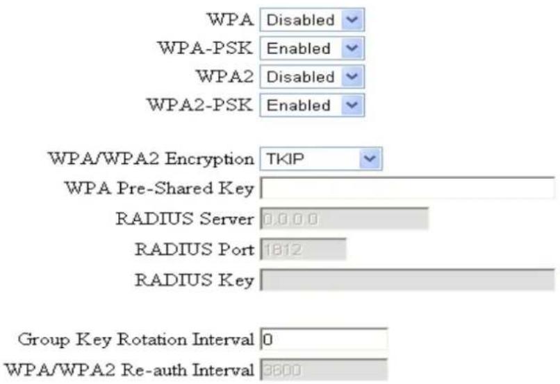
Fig. 35
Automatic Security Configuration
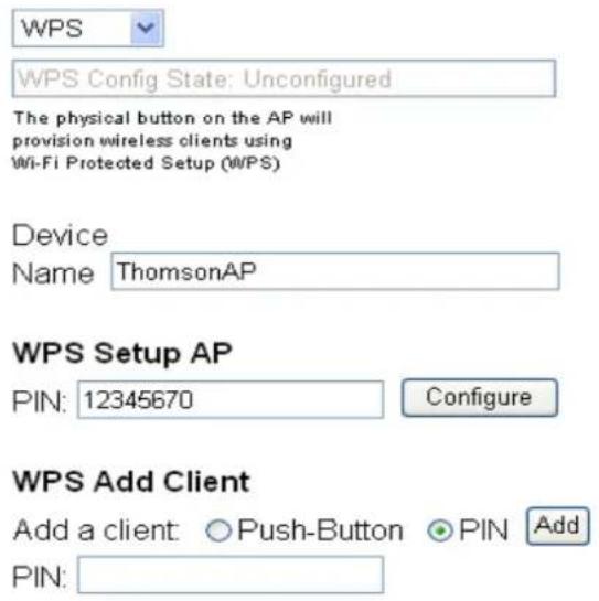
WiFi Protected Setup (WPS) is an easy and secure way of configuring and connecting your WiFi access point. In your case, the DCW775 is the Access Point (AP), and Your PC (or Wifi Device) is called the STA. When configuring your Wifi Network via WPS, Messages are exchanged between the STA and AP in order to configure the Security Settings on both devices.
WPS Config: It will help you to Enable or Disable the WPS feature. To enable you need to select WPS,
Illustrations contained in this document are for representation only.
Chapter 2: WEB Configuration
to disable you need to select Disabled.
Note: After you Enabled the WPS you will get the options as show in Fig.35 and the WPS Config State box will show its configuration status.
Device Name: By using this you can change the factory default to a name of your choice which is up to 32 characters long as like SSID.
WPS Setup AP: Here you do not need to change anything, just skip this step.
- WPS Add Client: There are two methods “Push-Button” and “PIN”. Select the method you want. But, the default selection will be “PIN”.
If you select "Push-Button", then the WPS Add Client option will appear as shown below.

Fig. 36
And then if you click "Add" button then WPS Setup AP page will appear as shown in Fig.36
WPS Setup AP
Your AP is now waiting for the STA to connect.

Fig. 37
WPS Configure Status. InProgress
And WPS Configure Status will be "In progress", after establishing the connection the WPS Configure Status will be "Success!" as shown below. After successful connection the client will get IP address from AP and then internet will be accessible.
Illustrations contained in this document are for representation only.
Chapter 2: WEB Configuration
WPS Setup AP SUCCESSFUL
AP Configuration is complete. Click 'Continue' to return to the previous page.

WPS Configure Status. Success!
Fig. 38
If you select WPS Method to PIN then it will ask for PIN while configuring the WiFi AP by showing a text box so, you need to enter PIN to establish the connection. You can get the PIN from your connected Wi-Fi client.
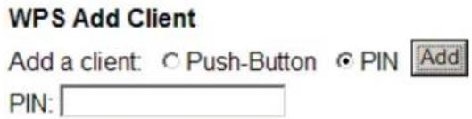
Fig. 39
PIN: Use this option to set the PIN, enter 4-8 digits PIN of the device you wish to configure. After entering the pin click "Add" button, then the WPS Setup AP page will appear as shown in Fig.38
WPS Setup AP
Your AP is now waiting for the STA to connect.

Fig. 40
Entered PIN: 54461147
WPS Configure Status. InProgress
And WPS Configure Status will be "In progress", after establishing the connection the WPS Configure Status will be "Success!" as shown below. After successful connection the client will get IP address from AP and then internet will be accessible.
62
Illustrations contained in this document are for representation only.
Chapter 2: WEB Configuration
Fig. 41
3. Access Control
This page allows you to make access control to the AP or connected clients by offering the MAC Addresses of the clients.
Fig. 42
63
Illustrations contained in this document are for representation only.
Chapter 2: WEB Configuration
MAC Restrict Mode : Click Disabled to welcome all of the clients on the network; select Allow to permit only the clients on the list to access the cable modem; or choose Deny to prevent the clients on the list to access this device.
MAC Address: Your Gateway identifies wireless PCs by their WiFi MAC Address. This address consists of a string of 6 pairs of numbers 0-9 and letters A-F, such as 00 90 4B F0 FF 50. It is usually printed on the WiFi card of the device (e.g. the PCMCIA card in a laptop). It can also be determined from a Windows DOS prompt as explained below.
Enter the MAC addresses of the connected clients into the fields, and then click Apply to add them to the list for access control.
Apply: After proper configuration, click Apply to invoke the settings.
Connected Clients : The information of currently connected clients will be displayed here.
4.802.11b/g Advanced
This page allows you to configure some advanced settings. The factory default values should provide good results in most cases. We don't recommend you change these settings unless you have technical knowledge of 802.11b wireless technology.
For expert users, details of all settings on this web page are provided below.
Fig. 43
Beacon Interval:
Chapter 2: WEB Configuration
Set the period of beacon transmissions to allow mobile stations to locate and identify a BSS. The measure unit is "time units" (TU) of 1024 microseconds. (Value range: 1~65535)
DTIM Interval:
The value you set here is used to inform mobile stations when multicast frames that have been buffered at the Wireless Voice Gateway will be delivered and how often that delivery occurs. (Value range: 1~255)
Fragmentation Threshold:
Set the number of the fragmenting frames to make the data to be delivered without errors induced by the interference. Frames longer than the value you set here are fragmented before the initial transmission into fragments no longer than the value of the threshold. (Value range: 256~2346)
RTS Threshold:
Set the value for sending a request to the destination. All the frames of a length greater than the threshold that you set here will be sent with the four-way frame exchange. And, a length less than or equal to the value that you set will not be proceeded by RTS. (Value range: 0~2347)
54g^TM Network Mode:
There are three modes for you to choose, please check the specification of your wireless card and choose a proper setting.
54g^TM Protection:
Select Auto to turn on the 54g^TM protection; select Off to turn down the protection.
Xpress™ Technology:
When Xpress is turned on, aggregate throughput (the sum of the individual throughput speeds of each client on the network) can improve by up to 27% in 802.11g-only networks, and up to 75% in mixed networks comprised of 802.11g and 802.11b standard equipment.
Rate:
It decides the speed of data transmission. There are several rates provided here for you to choose.
Choose any one of it according to your needs by using the drop-down menu.
Output Power:
To reduce the output power.
Chapter 2: WEB Configuration
5. Bridging
The Bridging page provides a location where settings can be adjusted related to the WDS (Wireless Distribution System) feature.
WDS is a system that enables the interconnection of access points wirelessly. It may also be referred to as repeater mode because it appears to bridge and accept wireless clients at the same time (unlike traditional bridging).
The wireless gateway can be placed in a mode that allows the gateway to communicate with other "extender" wireless access points either exclusively or mixed with communications to local PCs. Use this page to designate the Remote Bridges the gateway is allowed to communicate with, and to select the Wireless Bridging mode.
Fig. 44
Wireless Bridging: Choose Disabled to shutdown this function; select Enabled to turn on the function of WDS.
Remote Bridges: Enter the MAC Addresses of the remote Bridges to relay the signals for each other.
Apply: After proper configuration, click Apply to invoke the settings.
Chapter 2: WEB Configuration
6.802.11e QoS (WMM) Settings
Wi-Fi Multimedia (WMM) is a component of the IEEE 802.11e wireless LAN standard for quality of service (QoS). The QoS assigns priority to the selected network traffic and prevents packet collisions and delays thus improving VoIP calls and watching video over WLANs.
- Enable WMM:
This field allows you to enable WMM to improve multimedia transmission.
- Enable WMM No-Acknowledgement:
This field allows you to enable WMM No-Acknowledgement.
Power Save Support:
This field allows you to enable WMM Power-Save-Support.
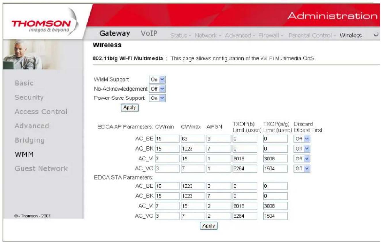
Fig. 45
Chapter 2: WEB Configuration
7. Guest Network
This page allows you to configure a guest network.
You can refer to the details described in previous sections to make the WiFi security settings and guest LAN settings.
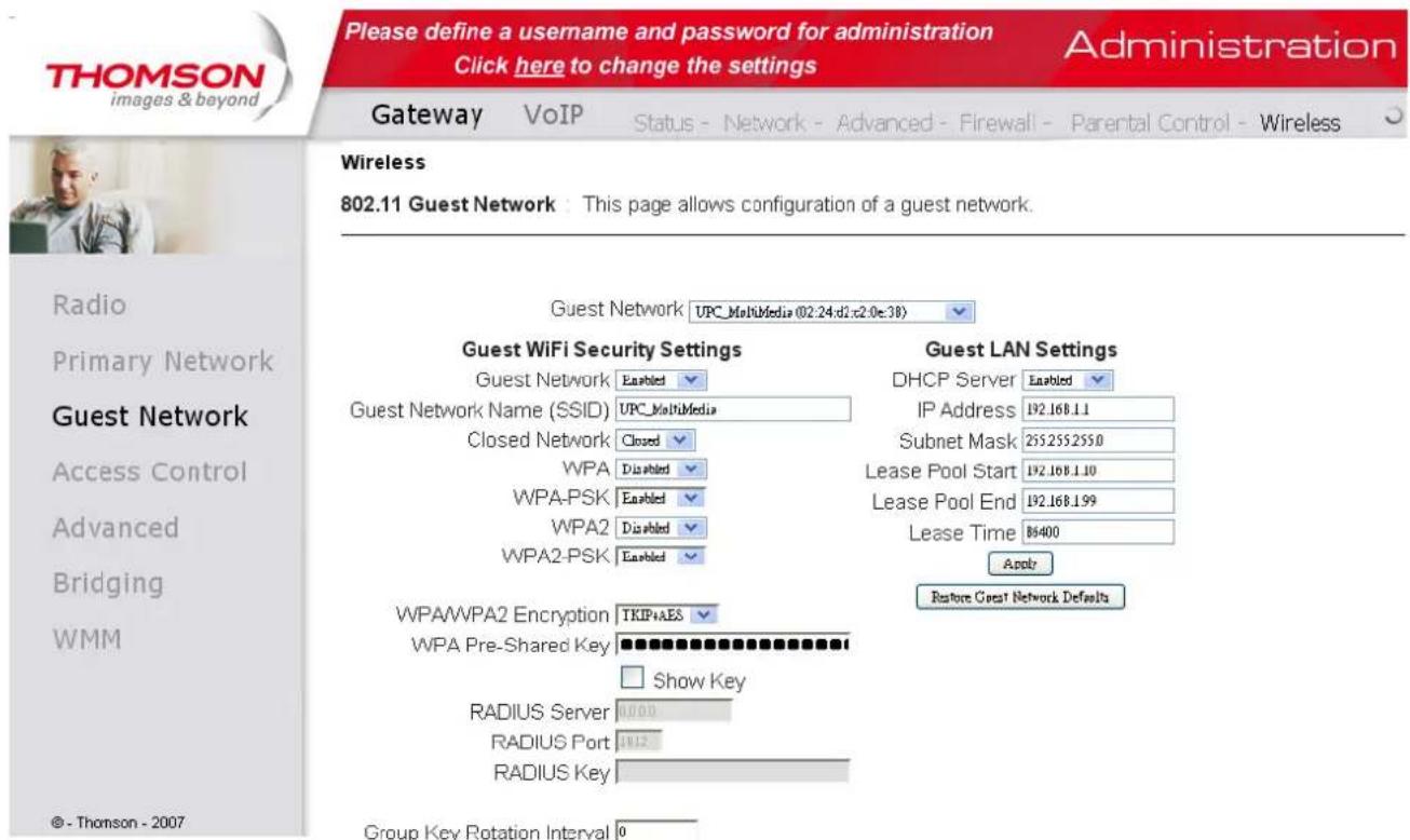
Fig. 46
Illustrations contained in this document are for representation only.
Chapter 2: WEB Configuration
VoIP - Basic Web Page Group
1. Basic LAN
This page displays the basic LAN status of this device, including the downstream and upstream status, device information, and interface parameters. You can select specific interface from the Interface Name drop-down menu.
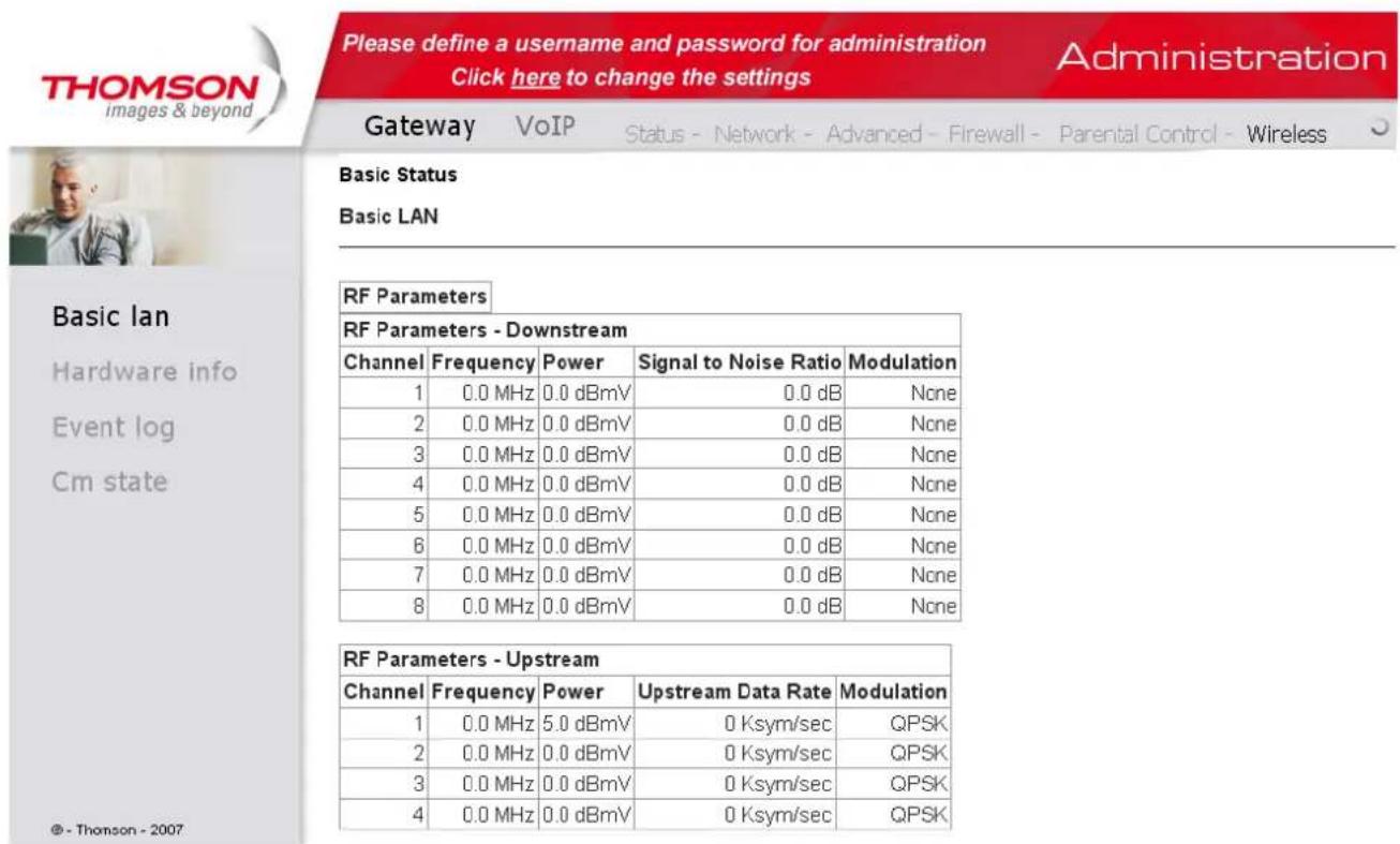
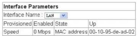
Fig. 47
69
Illustrations contained in this document are for representation only.
Chapter 2: WEB Configuration
2. Hardware Info
The hardware Info is displayed on this page.
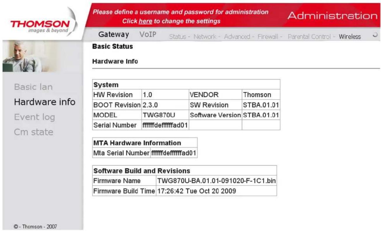
Fig. 48
3. Event Log
The event logs are displayed on this web page. You can check them whenever you need.
Illustrations contained in this document are for representation only.
Chapter 2: WEB Configuration
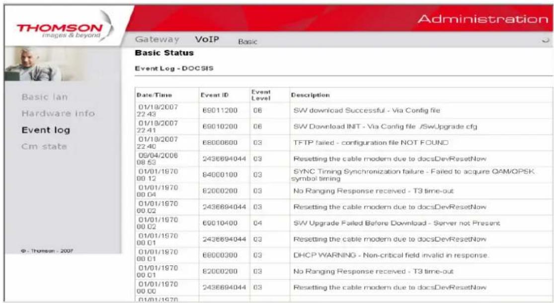
Fig. 49
4. CM State
This page shows the current state of the cable modem.
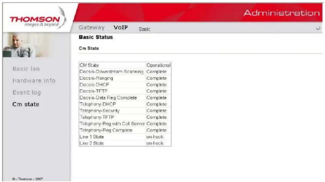
Fig. 50
71
Illustrations contained in this document are for representation only.
Chapter 3: Networking
Chapter 3: Networking
Communications
Data communication involves the flow of packets of data from one device to another. These devices include personal computers, Ethernet and USB hubs, cable modems, digital routers and switches, and highly integrated devices that combine functions, like the Wireless Cable Gateway.
The gateway integrates the functionality often found in two separate devices into one. It's both a cable modem and an intelligent wireless gateway networking device that can provide a host of networking features, such as NAT and firewall. Figure 2 illustrates this concept, with the cable modem (CM) functionality on the left, and networking functionality on the right. In this figure, the numbered arrows represent communication based on source and destination, as follows:
Type of Communication
- Communication between the Internet and your PCs
Example: The packets created by your request for a page stored at a web site, and the contents of that page sent to your PC.
- Communication between your cable company and the cable modem side
Example: When your cable modem starts up, it must initialize with the cable company, which requires the cable company to communicate directly with the cable modem itself.
- Communication between your PCs and the networking side
Chapter 3: Networking
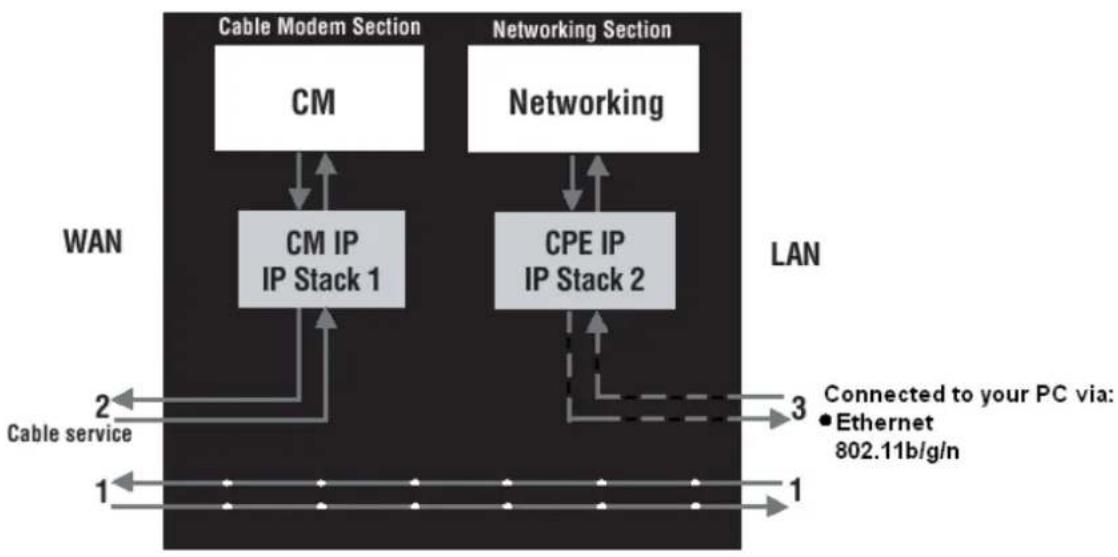
Fig.11
Example: The Wireless Cable Gateway offers a number of built-in web pages which you can use to configure its networking side; when you communicate with the networking side, your communication is following this path.
Each packet on the Internet addressed to a PC in your home travels from the Internet downstream on the cable company's system to the WAN side of your Wireless Cable Gateway. There it enters the Cable Modem section, which inspects the packet, and, based on the results, proceeds to either forward or block the packet from proceeding on to the Networking section. Similarly, the Networking section then decides whether to forward or block the packet from proceeding on to your PC. Communication from your home device to an Internet device works similarly, but in reverse, with the packet traveling upstream on the cable system.
Illustrations contained in this document are for representation only.
Chapter 3: Networking
Cable Modem (CM) Section
The cable modem (or CM) section of your gateway uses EURO-DOCSIS Standard cable modem technology. EURO-DOCSIS specifies that TCP/IP over Ethernet style data communication be used between the WAN interface of your cable modem and your cable company.
A EURO-DOCSIS modem, when connected to a Cable System equipped to support such modems, performs a fully automated initialization process that requires no user intervention. Part of this initialization configures the cable modem with a CM IP (Cable Modem Internet Protocol) address, as shown in Figure 3, so the cable company can communicate directly with the CM itself.
Networking Section
The Networking section of your gateway also uses TCP/IP (Transmission Control Protocol/Internet Protocol) for the PCs you connected on the LAN side. TCP/IP is a networking protocol that provides communication across interconnected networks, between computers with diverse hardware architectures and various operating systems.
TCP/IP requires that each communicating device be configured with one or more TCP/IP stacks, as illustrated by Figure 4. On a PC, you often use software that came with the PC or its network interface (if you purchased a network interface card separately) to perform this configuration. To communicate with the Internet, the stack must also be assigned an IP (Internet Protocol) address. 192.168.100.1 is an example of an IP address. A TCP/IP stack can
Chapter 3: Networking
be configured to get this IP address by various means, including a DHCP server, by you directly entering it, or sometimes by a PC generating one of its own.
Ethernet requires that each TCP/IP stack on the Wireless Cable Gateway also have associated with it an Ethernet MAC (Media Access Control) address. MAC addresses are permanently fixed into network devices at the time of their manufacture. 00:90:64:12:B1:91 is an example of a MAC address.
Data packets enter and exit a device through one of its network interfaces. The gateway offers Ethernet, USB, and 802.11b/g wireless network interfaces on the LAN side and the EURO-DOCSIS network interface on the WAN side.
When a packet enters a network interface, it is offered to all the TCP/IP stacks associated with the device side from which it entered. But only one stack can accept it — a stack whose configured Ethernet address matches the Ethernet destination address inside the packet. Furthermore, at a packet's final destination, its destination IP address must also match the IP address of the stack.
Each packet that enters a device contains source MAC and IP addresses telling where it came from, and destination MAC and IP addresses telling where it is going to. In addition, the packet contains all or part of a message destined for some application that is running on the destination device. IRC used in an Internet instant messaging program, HTTP used by a web browser, and FTP used by a file transfer program are all examples of applications. Inside the
Chapter 3: Networking
packet, these applications are designated by their port number. Port 80, the standard HTTP port, is an example of a port number.
The Networking section of the router performs many elegant functions by recognizing different packet types based upon their contents, such as source and destination MAC address, IP address, and ports.
Three Networking Modes
Your gateway can be configured to provide connectivity between your cable company and your home LAN in any one of three Networking Modes: CM, RG, and CH. This mode setting is under the control of your cable company, who can select the mode to match the level of home networking support for which you have subscribed. All units ship from the factory set for the RG mode, but a configuration file which the cable company sends the cable modem section during its initialization can change it.
Chapter 3: Networking
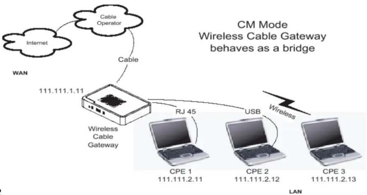
Cable Modem (CM) Mode
Fig. 12
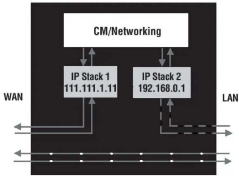
Fig. 13
CM (Cable Modem) Mode provides basic home networking. In this mode, two IP stacks are active:
Illustrations contained in this document are for representation only.
Chapter 3: Networking
- IP Stack 1 - for use by the cable company to communicate with the cable modem section only. This stack receives its IP address from the cable company during CM initialization. It uses the MAC address printed on the label attached to the Wireless Cable gateway.
- IP Stack 2 - for use by you, the end user, to communicate with the cable modem and Networking sections, to access the internal web page diagnostics and con guration. This stack uses a fixed IP address: 192.168.100.1. It uses a MAC address of MAC label + 1 (the MAC label is found on the bottom of the unit). E.g., if the MAC address is 00:90:64:12:B1:91, this MAC address would be 00:90:64:12:B1:92.
With CM Mode, your cable company must provide one IP address for the CM section, plus one for each PC you connect from their pool of available addresses. Your cable company may have you or your installer manually enter these assigned addresses into your PC, or use a DHCP Server to communicate them to your PCs, or use a method that involves you entering host names into your PCs.
Note that in CM Mode, packets passing to the Internet to/from your PCs do not travel through any of the IP stacks; instead they are directly bridged between the WAN and LAN sides.
Chapter 3: Networking
Residential Gateway (RG) Mode
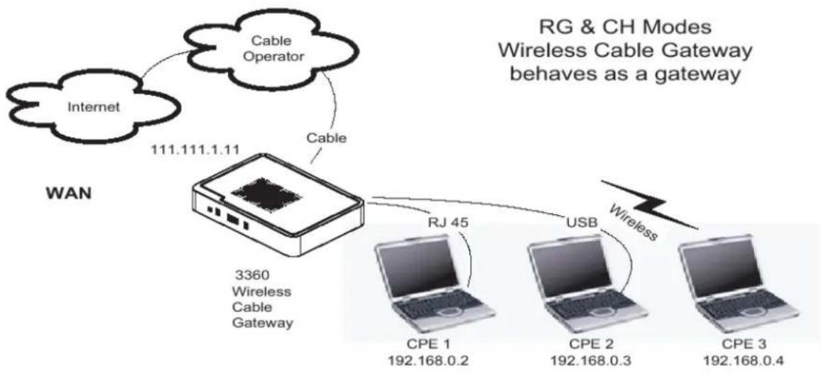
Fig. 14
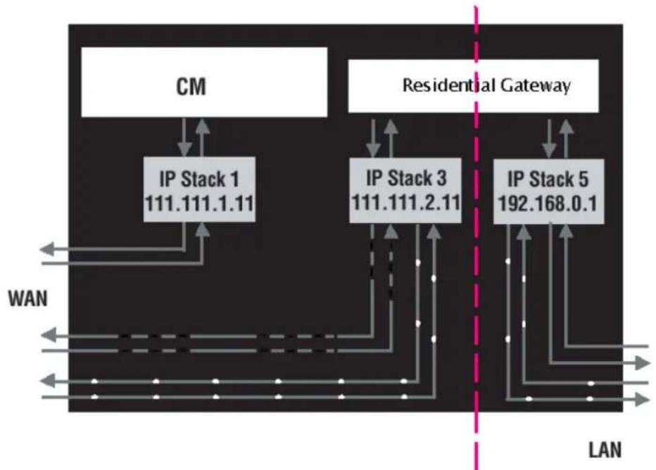
Fig. 15
RG (Residential Gateway) Mode provides basic home networking plus NAT (Network Address
Translation). In this mode, three IP stacks are active:
Illustrations contained in this document are for representation only.
Chapter 3: Networking
-
IP Stack 1 - for use by the cable company to communicate with the Cable Modem section only. This stack receives its IP address from the cable company during CM initialization. It uses the MAC address printed on the label attached to the Wireless Cable Gateway.
-
IP Stack 3 – for use by you to remotely (i.e. from somewhere on the WAN side, such as at your remote workplace) communicate with the Cable Modem and Networking sections, to remotely access the internal web page diagnostics and configuration. This stack is also used by your cable company to deliver packets between the Internet and the gateway's networking section so they can be routed to/from your PCs. This stack requires an IP address assigned by the cable company from their pool of available addresses. Your cable company may have you or your installer manually enter assigned addresses into your gateway, or use a DHCP Server to communicate them, or use a method that involves you entering host names. This stack uses a MAC address of MAC label +2 (the MAC label is found on the bottom of the unit). E.g., if the MAC address is 00:90:64:12:B1:91, this MAC address would be 00:90:64:12:B1:93.
-
IP Stack 5 – for use by you to locally (i.e. from somewhere on the LAN side in your home) communicate with the Cable Modem and Networking sections, to access the internal web page diagnostics and configuration. This stack is also used by the gateway's networking section to route packets between the gateway's Networking section and your PCs. This stack uses a fixed IP address: 192.168.0.1. It uses a MAC address of MAC label +4 (the MAC label is found on the bottom of the unit). E.g., if the MAC address is
Illustrations contained in this document are for representation only.
Chapter 3: Networking
00:90:64:12:B1:91, this MAC address would be 00:90:64:12:B1:95.
With RG Mode, your cable company must provide one IP address for the CM section, plus one for the Networking section, from their pool of available addresses. With RG Mode, each PC you connect gets an IP address from a DHCP Server that is part of the Networking section of the gateway.
Chapter 3: Networking
Chapter 4: Additional Information
Frequently Asked Questions
Q. What if I don't subscribe to cable TV?
A. If cable TV is available in your area, data and voice service may be made available with or without cable TV service. Contact your local cable company for complete information on cable services, including high-speed internet access.
Q. How do I get the system installed?
A. Professional installation from your cable provider is strongly recommended. They will ensure proper cable connection to the modem and your computer. However, your retailer may have offered a self installation kit, including the necessary software to communicate with your cable ISP.
Q. My modem is connected to the power sector but does not work
A. Check the ON/OFF button on the rear panel of your modem. Should be set to "1"
Q. Once my Wireless Voice Gateway is connected, how do I get access to the Internet?
A. Your local cable company provides your internet service*, offering a wide range of services including email, chat, and news and information services, and a connection to the World Wide Web.
Q. It seems that the wireless network is not working
A. Check the WiFi LED on the front panel. If it is no lighted, press on the WPS button (on the side of the modem) during 3 seconds and then check again the WiFi LED. If it is lighted, then the WiFi is enabled.
Q. Can I watch TV, surf the Internet, and talk to my friends through the Wireless Voice Gateway at the same time?
A. Absolutely!
Q. What do you mean by "Broadband?"
A. Simply put, it means you'll be getting information through a "bigger pipe," with more bandwidth, than a standard phone line can offer. A wider, "broader" band means more information, more quickly.
Q. What is Euro-DOCSIS and what does it mean?
A. "Data over Cable Service Interface Specifications" is the industry standard that most cable companies are adopting as they upgrade their systems. Should you ever decide to move, the Wireless Voice Gateway
Chapter 4: Additional Information
will work with all upgraded cable systems that are Euro-DOCSIS-compliant.
Q. What is Euro-PacketCable and what does it mean?
A. Euro-PacketCable is the industry standard for telephony services that most cable companies are adopting as they upgrade their systems. Should you ever decide to move, the Wireless Voice Gateway will work with all upgraded cable systems that are Euro-PacketCable compliant.
Q. What is Xpress Technology and what does it mean?
A. It is one of the popular performance-enhancing WiFi technologies, designed to improve wireless network efficiency and boost throughput. It is more efficient in mixed environments, and it can work with 802.11a/b/g networks. When Xpress is turned on, aggregate throughput (the sum of the individual throughput speeds of each client on the network) can improve by up to 27% in 802.11g-only networks, and up to 75% in mixed networks comprised of 802.11g and 802.11b standard equipment. The technology achieves higher throughput by re-packaging data, reducing the number of overhead control packets, so that more useful data can be sent during a given amount of time.
- Monthly subscription fee applies.
** Additional equipment required. Contact your cable company and ISP for any restrictions or additional fees.
Chapter 4: Additional Information
General Troubleshooting
You can correct most problems you have with your product by consulting the troubleshooting list that follows.
I can't access the internet.
- Check all of the connections to your Wireless Voice Gateway.
- Your Ethernet card or USB port may not be working. Check each product's documentation for more information.
- The Network Properties of your operating system may not be installed correctly or the settings may be incorrect. Check with your ISP or cable company.
All of the lights are flashing in sequence.
- This means the Wireless Voice Gateway is automatically updating its system software. Please wait for the lights to stop flashing. The updating process typically lasts less than one minute.
- Do not remove the power supply or reset the Wireless Voice Gateway during this process.
I can't get the modem to establish an Ethernet connection.
- Even new computers don't always have Ethernet capabilities – be sure to verify that your computer has a properly installed Ethernet card and the driver software to support it.
- Check to see that you are using the right type of Ethernet cable.
The modem won't register a cable connection.
- If the modem is in Initialization Mode, the INTERNET light will be flashing. Call your Cable Company if it has not completed this 5-step process within 30 minutes, and note which step it is getting stuck on.
- The modem should work with a standard RG-6 coaxial cable, but if you're using a cable other than the one your Cable Company recommends, or if the terminal connections are loose, it may not work. Check with your Cable Company to determine whether you're using the correct cable.
- If you subscribe to video service over cable, the cable signal may not be reaching the modem. Confirm that good quality cable television pictures are available to the coaxial connector you are using by connecting a television to it. If your cable outlet is "dead", call your Cable Company.
Chapter 4: Additional Information
- Verify that the Cable Modem service is Euro-DOCSIS compliant and Euro-PacketCable compliant by calling your cable provider.
I don't hear a dial tone when I use a telephone.
- Telephone service is not activated. If the rightmost light on the Wireless Voice Gateway stays on while others flash, check with your TSP or cable company.
- If the Wireless Voice Gateway is connected to existing house telephone wiring, make sure that another telephone service is not connected. The other service can normally be disconnected at the Network Interface Device located on the outside of the house.
- If using the second line on a two-line telephone, use a 2-line to 1-line adapter cable.
For more Usage and Troubleshooting Tips use the web site links provided on the CD-ROM: http://www.thomson.net/GlobalEnglish/Deliver/Cable/cable-modems-routers-gateway/Pages/default.aspx
Chapter 4: Additional Information
Service Information
If you purchased or leased your Wireless Voice Gateway directly from your cable company, then warranty service for the Digital Cable Modem may be provided through your cable provider or its authorized representative. For information on 1) Ordering Service, 2) Obtaining Customer Support, or 3) Additional Service Information, please contact your cable company. If you purchased your Wireless Voice Gateway from a retailer, see the enclosed warranty card.
Chapter 4: Additional Information
Glossary
10/100/1000 Mbps – Unshielded, twisted pair cable with an RJ-45 connector, used with Ethernet LAN (Local Area Network). “10/100/1000” indicates speed (10/100/1000 Mbps), “Base” refers to baseband technology, and “T” means twisted pair cable.
Authentication - The process of verifying the identity of an entity on a network.
DHCP (Dynamic Host Control Protocol) - A protocol which allows a server to dynamically assign IP addresses to workstations on the fly.
Ethernet adapters - A plug-in circuit board installed in an expansion slot of a personal computer. The Ethernet card (sometimes called a Network Interface Card, network adapter or NIC) takes parallel data from the computer, converts it to serial data, puts it into a packet format, and sends it over the 10/100/1000 Mbps LAN cable.
Euro-DOCSIS (Data Over Cable Service Interface Specifications) - A project with the objective of developing a set of necessary specifications and operations support interface specifications for Cable Modems and associated equipment.
F Connector - A type of coaxial connector, labeled CABLE IN on the rear of the Wireless Voice Gateway that connects the modem to the cable system.
HTTP (HyperText Transfer Protocol) – Invisible to the user, HTTP is used by servers and clients to communicate and display information on a client browser.
Hub - A device used to connect multiple computers to the Wireless Voice Gateway.
IP Address - A unique, 32-bit address assigned to every device in a network. An IP (Internet Protocol) address has two parts: a network address and a host address. This modem receives a new IP address from your cable operator via DHCP each time it goes through Initialization Mode.
Key exchange - The swapping of mathematical values between entities on a network in order to allow encrypted communication between them.
MAC Address - The permanent "identity" for a device programmed into the Media Access Control layer in the network architecture during the modem's manufacture.
NID - Network Interface Device, the interconnection between the internal house telephone wiring and a conventional telephone service provider's equipment. These wiring connections are normally housed in a
Chapter 4: Additional Information
small plastic box located on an outer wall of the house. It is the legal demarcation between the subscriber's property and the service provider's property.
Euro-PacketCable - A project with the objective of developing a set of necessary telephony specifications and operations support interface specifications for Wireless Voice Gateways and associated equipment used over the Euro-DOCSIS based cable network.
PSTN (Public Switched Telephone Network) - The worldwide voice telephone network which provides dial tone, ringing, full-duplex voice band audio and optional services using standard telephones.
Provisioning - The process of enabling the Media Terminal Adapter (MTA) to register and provide services over the network.
TCP/IP (Transmission Control Protocol/Internet Protocol) – A networking protocol that provides communication across interconnected networks, between computers with diverse hardware architectures and various operating systems.
TFTP - Trivial File Transfer Protocol, the system by which the Media Terminal Adapter's configuration data file is downloaded.
TSP - Telephony Service Provider, an organization that provides telephone services such as dial tone, local service, long distance, billing and records, and maintenance.
Universal Serial Bus (USB) - USB is a "plug-and-play" interface between a computer and add-on devices, such as a Wireless Voice Gateway.
Xpress Technology - One of the popular performance-enhancing WiFi technologies, designed to improve wireless network efficiency and boost throughput. It is more efficient in mixed environments, and it can work with 802.11a/b/g networks.
Please do not send any products to the Indianapolis address listed in this manual or on the carton. This will only add delays in service for your product.
Thomson Inc.
101 W. 103^rd St., INH700
Indianapolis, IN 46290
USA
- CAUTION
- NORTH AMERICAN CABLE INSTALLER:
- Table of Contents
- Euro-PacketCable and Euro-DOCSIS compliant
- Operating Information
- Product Information
- List of Figures
- Gateway - Status Web Page Group 26
- Gateway - Network Web Page Group 34
- Gateway - Advanced Web Page Group 40
- Gateway - Firewall Web Page Group 48
- Gateway - Parental Control Web Page Group 51
- Wireless Voice Gateway Features
- Chapter 1: Connections and Setup
- What's on the CD-ROM
- CD-ROM Contents:
- Computer Requirements
- Wall Mounting
- To do this:
- Front Panel
- Rear Panel
- What the Modem Does
- What the Modem Needs to Do Its Job
- Contact Your Local Cable Company
- Please verify the following with the cable company
- Important Information
- Please verify the following on the Wireless Voice Gateway
- Attaching the Cable TV Wire to the Wireless Voice Gateway
- Important Connection Information
- Ethernet Connection to a Computer
- Connecting More Than A Computer to the Wireless Voice Gateway
- Telephone or Fax Connection
- Turning on the Wireless Voice Gateway
- Chapter 2: WEB Configuration
- Accessing the Web Configuration
- Outline of Web Manager
- Warning message to change the password
- Gateway - Status Web Page Group
- Software
- THOMSON
- Please define a username and password for administration
- Click here to change the settings
- Administration
- Connection
- Password
- More information
- Error converting one or more entries:
- Diagnostics
- 5.Event Log
- Initial Scan
- Backup/Restore
- LAN
- IP Address and Subnet Mask:
- DHCP Server:
- WAN
- Computers
- DDNS - Dynamic DNS service
- Time server
- Options
- IP Filtering
- MAC Filtering
- Port Filtering
- Forwarding
- Port Triggers
- DMZ Host
- RIP (Routing Information Protocol) Setup
- Web Content Filtering
- TOD Filtering
- Local Log and Remote Log
- Gateway - Parental Control Web Page Group
- Basic
- Performance
- Authentication
- Security
- 802.11b/g/n Radio
- 2.802.11b/g/n Security - Primary Network
- Fig. 32
- 802.1x Authentication
- WPA/WPA2
- WPA-PSK/WPA2-PSK
- Automatic Security Configuration
- WPS Setup AP
- WPS Setup AP SUCCESSFUL
- 62
- Access Control
- 4.802.11b/g Advanced
- Beacon Interval:
- DTIM Interval:
- Fragmentation Threshold:
- RTS Threshold:
- 54gTM Network Mode:
- 54gTM Protection:
- Xpress™ Technology:
- Rate:
- Output Power:
- Bridging
- 6.802.11e QoS (WMM) Settings
- - Enable WMM:
- - Enable WMM No-Acknowledgement:
- Power Save Support:
- Guest Network
- Basic LAN
- Hardware Info
- Event Log
- CM State
- Chapter 3: Networking
- Communications
- Type of Communication
- Cable Modem (CM) Section
- Networking Section
- Three Networking Modes
- Chapter 4: Additional Information
- Frequently Asked Questions
- What is Euro-PacketCable and what does it mean?
- What is Xpress Technology and what does it mean?
- I don't hear a dial tone when I use a telephone.
- Thomson Inc.
Brand : THOMSON
Model : TWG870
Category : Wireless Router