
iM3C Series - EV charging station VISION - Free user manual and instructions
Find the device manual for free iM3C Series VISION in PDF.
| Product Type | Electric Vehicle Charging Station |
| Brand | VISION |
| Model | iM3C Series (iM3C-09K6A, iM3C-11K5A, iM3C-15K6A, iM3C-19K2A) |
| Rated Current | 40 A (iM3C-09K6A), 48 A (iM3C-11K5A), 65 A (iM3C-15K6A), 80 A (iM3C-19K2A) |
| Operating Temperature Range | -30 °C to 50 °C |
| Compliance Standards | FCC Part 15, Industry Canada CNR (license-exempt device) |
| Safety Distance | Minimum 20 cm from persons |
| Installation | On non-combustible materials, by qualified personnel only |
| Recommended Maintenance | Safety check at least once a week |
| Cleaning | With a clean dry cloth, do not use wet products |
| Safety - Cable | Do not use if the cable is frayed, insulation broken or damaged |
| Safety - Enclosure | Do not use if the enclosure is broken, cracked or open |
| Usage - Vehicle | Charge only with engine off and vehicle stationary |
| Usage - Restrictions | Prohibited for minors and persons with limited mobility |
| Electrical Protection | Overcurrent protection (branch circuit breaker) |
| In Case of Defect | Contact the supplier immediately |
Frequently Asked Questions - iM3C Series VISION
User questions about iM3C Series VISION
0 question about this device. Answer the ones you know or ask your own.
Ask a new question about this device
Download the instructions for your EV charging station in PDF format for free! Find your manual iM3C Series - VISION and take your electronic device back in hand. On this page are published all the documents necessary for the use of your device. iM3C Series by VISION.
USER MANUAL iM3C Series VISION
Level 2 AC EV Charging station
User Manual

Intertek
5027451

FCC ID: 2AZGWIM3C-2309

IMPORTANT SAFETY INSTRUCTIONS
WARNING- When using electric products, basic precautions should always be followed, including the following. This manual contains important instructions for Models iM3C-09K6A, iM3C-11K5A, iM3C-15K6A and iM3C-19K2A that shall be followed during installation, operation, and maintenance of the unit.
- Read all the instructions before using this product.
- This device should be supervised when used around children.
- Do not put fingers into the electric vehicle connector.
- Do not use this product if the flexible power cord or EV cable is frayed, has broken insulation, or any other signs of damage.
- Do not use this product if the enclosure or the EV connector is broken, cracked, open, or shows any other indication of damage.
- Indicate the ambient temperature rating, -30^ to 50^ .
- "CAUTION" and the following or equivalent: "To reduce the risk of fire, connect only to a circuit provided with @ amperes maximum branch circuit overcurrent protection in accordance with the National Electrical Code, ANSI/NFPA 70, and the Canadian Electrical Code, Part I, C22.1."
Note (@)
| Model | Current Rating |
| iM3C-09K6A | 40A |
| iM3C-11K5A | 48A |
| iM3C-15K6A | 65A |
| iM3C-19K2A | 80A |
CONSIGNES DE SECURITÉ IMPORTANTES
1.ABBREVIATIONS. 4
2. SAFETY NOTES 5
2.1. Safety signs used 5
2.2. Installation 6
2.3.Maintenance 7
2.4. Operation 7
- STANDARDS COMPLIANCE 9
3.1. Standard(s) for safety 9
3.2. AC Level 2 Charging 9
3.3. Charging mode and connection 9
3.4. Charging interface 9
- -PRODUCT INFORMATION 11
4.1. General 11
4.2. Specifications 12
4.3. Nameplate 14
- INSTALLATION 15
5.1.Unpacking 15
5.2.Prepare 16
5.3. Installation steps 18
5.4. Empty socket 21
- OPERATION 22
6.1. Power on 22
6.2. Human-Machine Interface 22
6.3. Config the parameters 26
6.4. Start Charging 30
6.5. Normally stop charging 31
6.6.Abnormally stop charging 31
- FAULT HANDLING AND MAINTENANCE 32
7.1. Fault Handling 32
7.2.Maintenance 34
- Moving and Storage 34
8.1.Moving 34
8.2. Storage 34
WARRANTY AGREEMENT 35
1. ABBREVIATIONS
| S/N | Abbreviations | Description |
| 1 | IEC | International Electrotechnical Commission |
| 2 | EV | Electrical Vehicle, this can be BEV (battery EV) or PHEV (plug-in hybrid EV) |
| 3 | EVSE | Electric Vehicle Supply Equipment [IEC61851-1] |
| 4 | OBC | On-board charger (of an EV) |
| 5 | kW | Kilo Watt (unit of Power) |
| 6 | A | Ampere (unit of Current) |
| 7 | V | Volt (unit of Voltage) |
| 8 | Hz | Hertz (unit of Frequency) |
| 9 | LCD | Liquid Crystal Display |
| 10 | LED | Light-emitting Diode |
| 11 | RFID | Radio Frequency Identification |
| 12 | CMS | Central Management System, manages EVSE and has the information for authorizing users for using its EVSE. |
| 13 | OCPP | Open Charge Point Protocol A standard open protocol for communication between EVSE and a Central System and is designed to accommodate any type of charging technique. (www.openchargealliance.org) |
| 14 | HMI | Human-Machine Interface |
| 15 | CCID | Charging Circuit Interrupting Device |
| 16 | GM/I | Ground Monitor Interruptions |
| 17 | GFCI | Ground Fault Circuit Interruptions |
2. SAFETY NOTES
2.1. Safety signs used
The following warning signs, mandatory signs and information signs are used in this manual, on and in the AC EV Charger.
CAUTION: Warning of electrical hazards.
This sign is intended to alert the user that severe personal injury or substantial property damage can result if the device is not operated as requested.
ATTENTION: Warning of a danger spot or dangerous situation.
This sign is intended to alert the user that minor personal injury or material damage can result, if the device is not operated as requested.
CAUTION: Do not touch by hands in case of ESD.
Indicates the possible consequences of touching electrostatically sensitive components.
No access for unauthorized persons.
Use protective footwear.
Must wear a safety helmet.
Indicates important texts, notes, or tips.
Safety protection must be done when installing the EV Charger.
Installation must be carried out by personnel with professional qualification, otherwise there is a risk of electric shock.
It shall be installed in the place without violent vibration and impact, and placed vertically to facilitate ventilation.
Do not drop any foreign objects, especially metal objects, into the inside of the Charger or there is a risk of fire.
The lead nose of the Charger must be securely attached or there is a risk of damaging the equipment.
Personnel must always use protective footwear when maintenance work.
It is recommended that routine safety inspection visits to Charger be conducted at least once a week.
Do not put inflammable, explosive, or combustible materials, chemicals, combustible steam, and other dangerous goods near the Charger, otherwise there is a risk of fire.
- Keep the charging adapter clean and dry and wipe with a clean, dry cloth if soiled. Do not touch the Charger with your hand when charged.
Strictly forbidden for minors or persons of restricted capacity to approach the Charger to avoid injury.
Forced charging is strictly forbidden when the electric vehicle or Charger fails.
Electric vehicle can only be charged with the engine off and stationary. Do not charge in rainy and thunderous weather.
It is strictly prohibited to use the Charger when the charging adapter or charging cables are defective, cracked, worn, broken or the charging cables is exposed. If you find any, please contact the supplier in time.
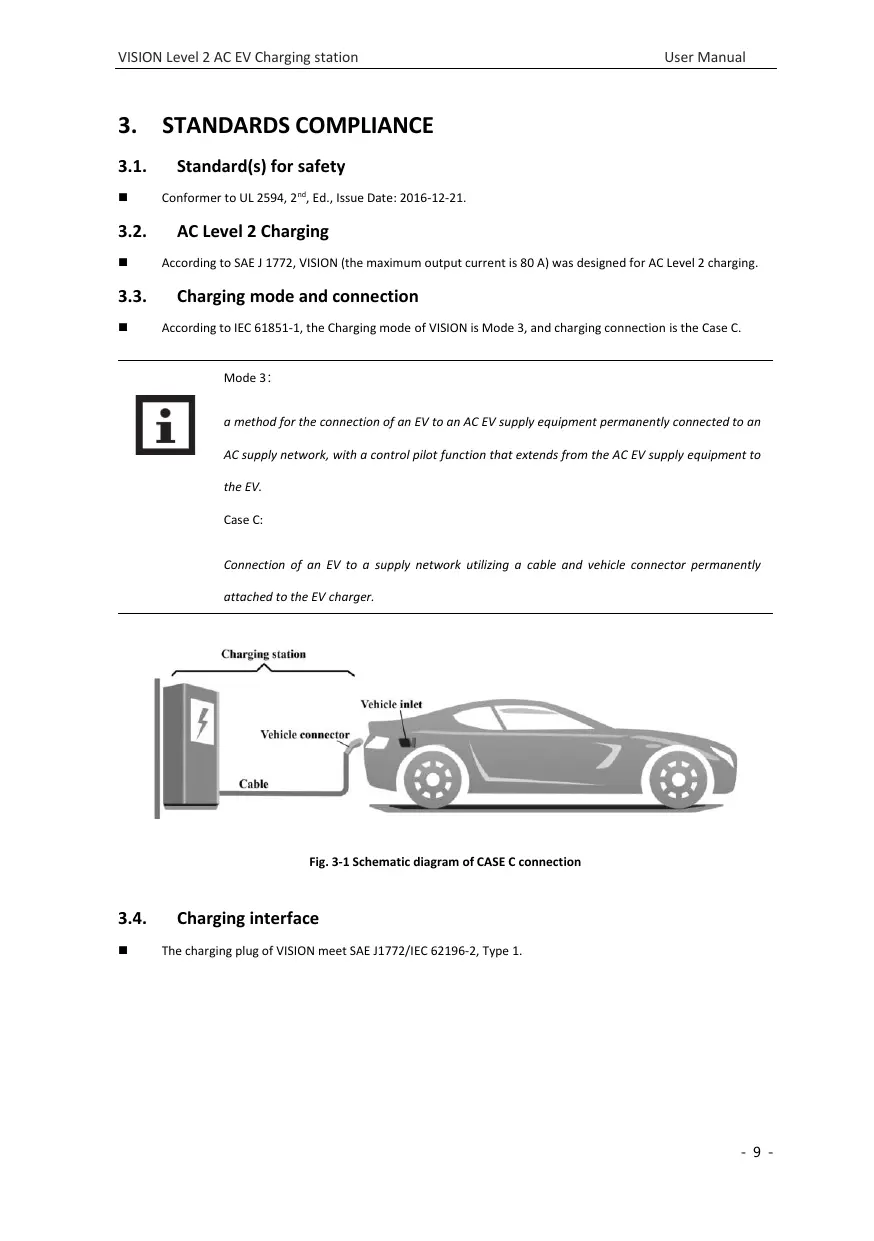
3.1. Standard(s) for safety
Conformer to UL 2594, 2^nd , Ed., Issue Date: 2016-12-21.
3.2. AC Level 2 Charging
According to SAE J 1772, VISION (the maximum output current is 80 A) was designed for AC Level 2 charging.
3.3. Charging mode and connection
According to IEC 61851-1, the Charging mode of VISION is Mode 3, and charging connection is the Case C.

Mode 3:
a method for the connection of an EV to an AC EV supply equipment permanently connected to an AC supply network, with a control pilot function that extends from the AC EV supply equipment to the EV.
Case C:
Connection of an EV to a supply network utilizing a cable and vehicle connector permanently attached to the EV charger.
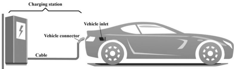
Fig. 3-1 Schematic diagram of CASE C connection
3.4. Charging interface
The charging plug of VISION meet SAE J1772/IEC 62196-2, Type 1.
■ VISION provide a Type 1 female plug with charging cable, it only charging an EV with a Type 1 charging socket

(a) Socket
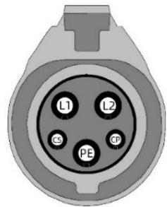
(b) Plug
Fig. 3-2 Schematic diagram of Type 1 interface
(vehic1e inlet).
4. -PRODUCT INFORMATION
4.1. General
Welcome to use Level 2 AC EV charger VISION by our company.
The shape & dimensions of VISION shown as Fig. 4-1.
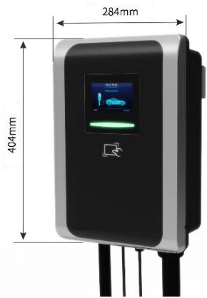
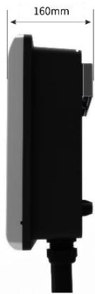
Fig. 4-1 The shape & dimensions of VISION
4.1.2. Block diagram
The block diagram of VISION AC EV charger is shown as Fig. 4-2.
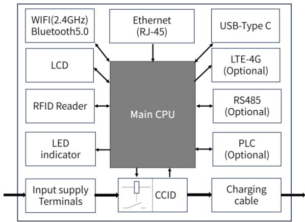
Fig. 4-2 Block diagram of VISION
It is widely used in various household electric vehicle charging in North America, as well as various chargers, parking lots, community garages and public electric vehicle charging places.
4.1.3. Model number definition
The model number definition of charger follows the rules as shown in Fig. 4-3.
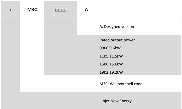
Fig. 4-3 Model number definition
4.2. Specifications
4.2.1. Electrical specifications
| Model Number | iM3C-09K6A | iM3C-11K5A | iM3C-15K6A | iM3C-19K2A |
| Rated Voltage | 240V/208V (AC Level 2 Charging), 50/60Hz | |||
| Rated Current | 40A | 48A | 65A | 80A |
| Rated Power | 9.6kW (@240VAC) | 11.5Kw (@240VAC) | 15.6kW (@240VAC) | 19.2Kw (@240VAC) |
| Recommended Input cable | Cable: 4×8AWG, copper. | Cable: 4×6 AWG, copper. | ||
| Charging interface | IEC 62196-2, Type 1 plug with 5m cable Note: That cord extension sets are not be used. | |||
4.2.2. Functional description
| Charging Mode | Mode 3 |
| Charging Control | Remote: “APP-controlled”Local: “Plug-and-Play” or “Card-controlled” |
| Display Screen | 4.3-inch LCD touch screen (display charging current, voltage, energy, charging time, state & fault information, etc.) |
| Indicator Lights | Multi-color atmosphere lights |
| Communication interface | WIFI (2.4GHz), Ethernet (RJ-45 interface), Bluetooth, TTLAnd support OCPP 1.6J Protocol (Optional) |
| Communication interface(Optional) | 4G Nano SIM card (LTE Cat 4, suitable for AT&T/ Verizon, LTE-FDD:B2/B4/B5/B12/B13/B14/B66/B71; WCDMA: B2/B4/B5). |
| Communication interface(Optional) | RS-485 with special communication protocolRS-232 |
| Safety Protection | Surge protection, over temperature, over/under voltage, over current, ground protection |
| CCID built-in | Yes, CCID 20 |
4.2.3. Mechanical parameters
| Mounting | Wall-mounted or pole-mounted (mounting pole is optional) |
| Net Weight | 10kg |
| Dimension | H×W×D = 404mm × 284mm × 160mm |
| Color & Material | White and Black, PC |
| Enclosure rated | Type 4 |
4.2.4. Ambient conditions
| Altitude | ≤ 2000m |
| Storage temperature | -40 ~ 75°C |
| Operation temperature | -30 ~ 50°C |
| Relative humidity | ≤ 98%RH, no water droplet condensation |
| Vibration | < 0.5G, no acute vibration and impaction |
| Installation location | Indoor or outdoor, good ventilation, no flammable, explosive gases |
4.3. Nameplate
On the VISION shell, there is a nameplate identifying the model and specification of the charger, the content is shown as Fig. 4-4.
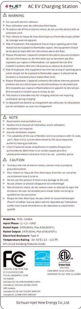
Fig. 4-4 The content of the nameplate
5. INSTALLATION
5.1. Unpacking
5.1.1. Packing list
| Package | Quantity |
| AC EV Charging station | 1 pc |
| Empty socket | 1 pc |
| RFID card | 2 pcs |
| Wall-mounting accessories (including A+B+C+D as Fig. 5-1 shown) | 1 set |
| User manual | 1 pc |
| Quality certificate | 1 pc |
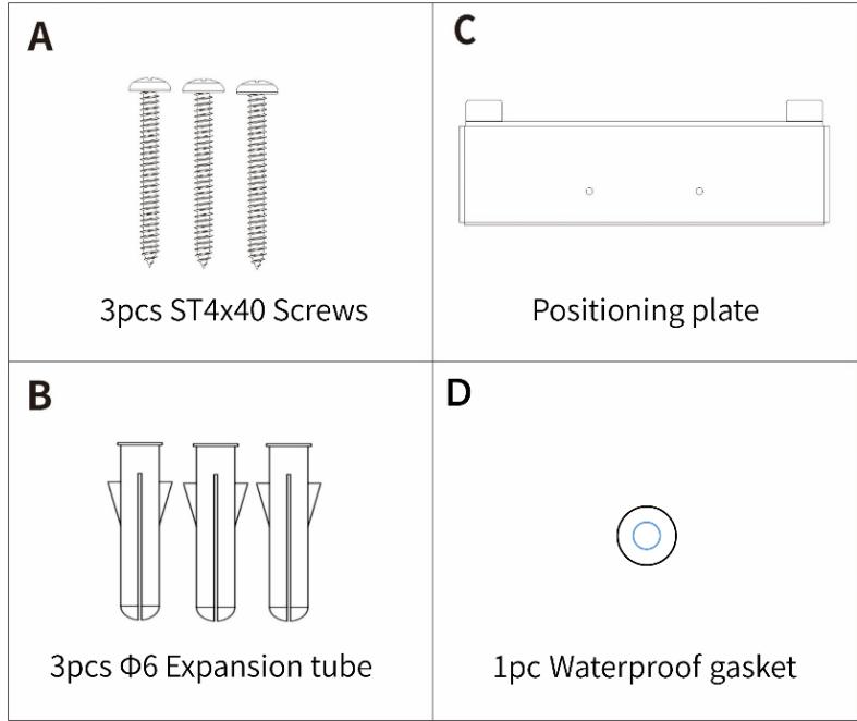
Fig. 5-1 Wall-mounting accessories
5.1.2. Inspection & confirm
When unpacking, please carefully confirm the following points:
Whether the accessories are missing according to the packing list.
Whether there is any damage during transportation.
Whether the model and specification of the machine's nameplate are consistent with the order requirements.

If any damage or missing parts are found, please do not start the machine, and contact the supplier as soon as possible.
Please keep the packing box and packing materials 1 month for future handling.

The paper packaging is recyclable.
5.2. Prepare
When transporting or moving the EV charger, pay attention to the following points to ensure product safety:

This product is electrical equipment. It should be handled with care to avoid violent vibration and impact.
The charger shall not be transported by dragging the charging connector and the charging cable.
In order to ensure the long-term stable operation of the product, it is recommended to avoid installing chargers in extreme weather as far as possible, especially low or high ambient temperature may affect the installation effect due to thermal expansion and cold contraction.
The electrical power supply receptacle (NEMA 14-50R) must be prepared.
Space requirement: When the charger is fixed on the wall, the minimum space requirements are shown in Fig. 5-2.
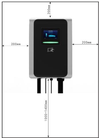
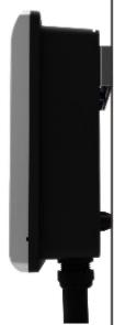
Fig. 5-2 Minimum space requirements for wall mounting
It is suggested that the charger should be installed in a place with good ventilation, no direct sunlight and shelter from wind and rain. In order to ensure good ventilation condition, you should mount the charger vertically and leave enough space.
Tools for installation
Prepare the following tools at least before installing the VISION AC EV Charging Station.
| No. | Tools' Name | Schematic Picture | Main Uses |
| 1 | Multimeter | Check the electrical connection and measure the voltage | |
| 2 | Electric Impact drill | Drill fixing holes in the wall | |
| 3 | Wrench | Fastening bolt | |
| 4 | Diagonal plier | Cut the cable | |
| 5 | Wire stripper | Peeling cables | |
| 6 | Crimping plier | Pressed cable terminal | |
| 7 | Cross screwdriver | Fastening screw | |
| 8 | T10 Torx screwdriver | Fastening screw |
5.3. Installation steps
5.3.1. Drill fixing holes
Drill 3 holes with diameter of 6mm and depth of at least 50mm on the wall as installation map. Install the Mounting Accessory-B 6 Expansion tube into the holes.
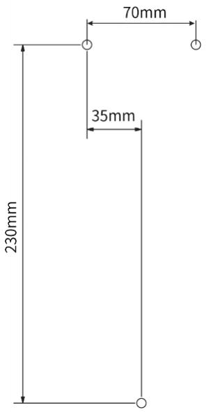
Fig. 5-3 Installation map
5.3.2. Fix positioning plate
Use two screws Mounting Accessory-A to install the positioning plate on the wall.
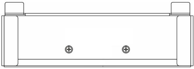
Fig. 5-4 Fix the plate
5.3.3. Open the cover
Unfasten the button M3 screw with T10 Torx screwdriver as step [A],
Pry off the front cover from the hole on the side with slotted screwdriver as step [B].
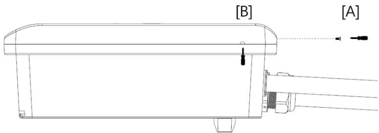
Fig. 5-5 Open the front cover
Unfasten the six screws and remove the terminal cover.
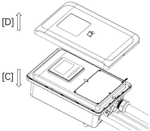
Fig. 5-6 Open the terminal cover
5.3.4. Wiring
- Pass the prepared power cable through the input cable interface, connect each cable to the input terminals according to the terminal label L1 L2 and GND as shown in Fig. 5-7.
- If you have optional functions, please follow the prompts [A] and [B] to connect, such as RS485 and 4G SIM card.
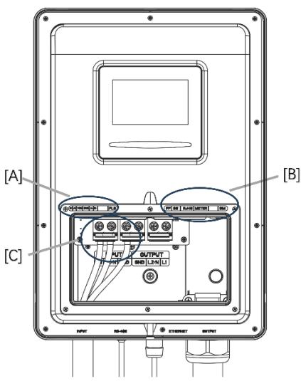
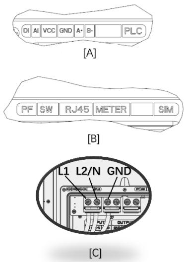
Fig. 5-7 wiring
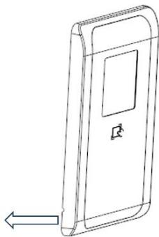
5.3.5. Fix the Charging station
First step: Install the charger on the wall in the direction of the arrow;
Second step: Use the installation accessory-A screw cross the installation accessory-D waterproof gasket to fix the charger.
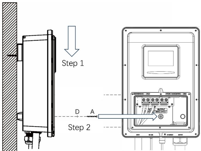
Fig. 5-8 Fix the charger
5.3.6. Fix the Cover
Step A: Close the terminal cover and fasten the six screws;
Step B: Install the front cover on the charger
Step C: Fasten the button screw.
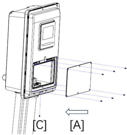
[B]
Fig. 5-9 Fix the Cover
5.4. Empty socket
VISION AC EV charger config a type 1 charging connector. When the charger is in standby state, please plug the charging plug in the empty socket in order to protect the charging plug.
Please use expansion screws to fix this empty socket at a suitable position beside the Charging Station.

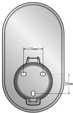
Fig. 5-10 Empty socket
6. OPERATION
6.1. Power on
After the charger has been installed and confirmed, switch on the power supply. The light and screen lights up and the charger switches to standby state.
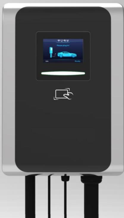
6.2. Human-Machine Interface
6.2.1. Overview
As shown in Fig. 6-1, VISION is configured with multiple human-machine interfaces.
Fig. 6-1 HMI of VISION
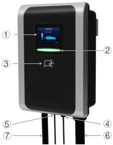
① LCDscreen
③ RFID reader
⑤ Communication interface
⑦ Input cable
② LEDindicator
④ Ethernet interface
⑥ Charging cable
6.2.2. LCD screen
Vision config a 4.3-inch LCD touch screen, which is mainly used to display various status information and set parameters of the charger shown as Fig. 6-2.
Icons or instructions in each display area
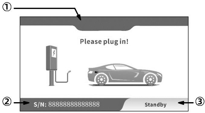
Fig. 6-2 Display of icons and instructions
In Fig. 6-2, there are three areas to display icons or instructions, with the specific meanings as follows:
| NO. | Icon | Connotation |
| Area ① | ||
| 1 | No icon | Off-line or no network |
| 2 | Connect to router via Wifi | |
| 3 | Exchange data with CMS via Wifi | |
| 4 | Connect to router via Ethernet | |
| 5 | Exchange data with CMS via Ethernet | |
| 6 | 4G | Connect to internet via 4G |
| 7 | 4G | Exchange data with CMS via 4G |
| Area ② | ||
| 8 | S/N: 8888888888888888 | The serial number of the charging station |
| Area ③ | ||
| 9 | Standby | Current state of the charging station |
| 10 | Connect successful | Charging connector is properly connected to EV |
| 11 | Charging | Charging state |
| 12 | Charging finished | Finished, please follow the instructions on the screen |
| 13 | Failure to start | Failure to start, please follow the instructions on the screen |
| 14 | System failure | Fault state, please follow the instructions on the screen |
| 15 | System upgrading | Upgrade state, please follow the instructions on the screen |
As shown in Fig. 6-3, the LCD screen displays 4 types picture in normal charging process.
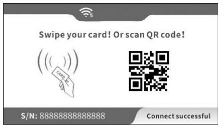
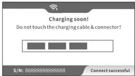
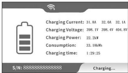
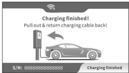
Fig. 6-3 Display of normal charging
If the charging process fails or the equipment fails, the picture displayed on the LCD screen is shown in Fig. 6-4.
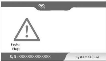
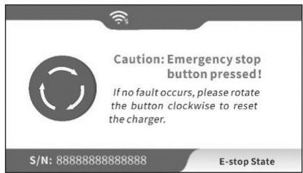
Fig. 6-4 Display of fault state
6.2.3. LED indicator
The LED indicator on the panel are used to indicate the status of the charger and the various combinations of
indicators are described as below.
| No. | Indicator Color | Indicator Status | Connotation |
| 1 | Blue | ON | Standby status (Connected to the network) |
| Twinkle | Standby status (Unconnected network) | ||
| OFF | Power off | ||
| 2 | Green | Slow twinkle | Connected to an EV |
| Fast twinkle | Start charging status | ||
| ON | Charging status | ||
| 3 | Red | Twinkle | System failure |
| OFF | No fault |
6.2.4. RFID reader
In general, the charger is equipped with RFID card reader as standard, and the charging process can be started and stopped by using the RFID card (shown as Fig. 6-5) configured with the host. The special customized card swiping function is not separately described here.
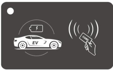
Fig. 6-5 RFID card
6.3. Config the parameters
6.3.1 Config parameters Via offline configuration page
Taking the configuration of charger parameters by laptop as an example, it is introduced as follows (the method of setting parameters by mobile phone is similar and will not be repeated):
Step 1: connect to WiFi hotspot
Keep your laptop in a state where it can connect to WiFi hotspots. Within ten minutes after power on, the charger provides a WiFi hotspot as the access entrance for parameter configuration. Connect a WiFi hotspot with a name is similar to "M3C-12345678" in the "WiFi network" of the laptop. It is no password to connect the hotspot.

Fig. 6-6 Connect the WiFi in Windows OS
Step 2: login to setting
Enter 192.168.4.1 in the address bar of Google Chrome or Microsoft Edge, you can access the EVSE CONFIGURATION shown in Fig. 6-7, and Microsoft IE cannot access this IP address.

Fig. 6-7 Login of EVSE CONFIGURATION
Step 3: Config your EV Charger
Enter the correct login password to enter the page shown in Fig. 6-8. The factory default password is 12345678. Please change the password upon your first login. As shown in Fig. 6-8 set the parameters on this page.
EVSE CONFIGURATION
User Options
Advanced Options
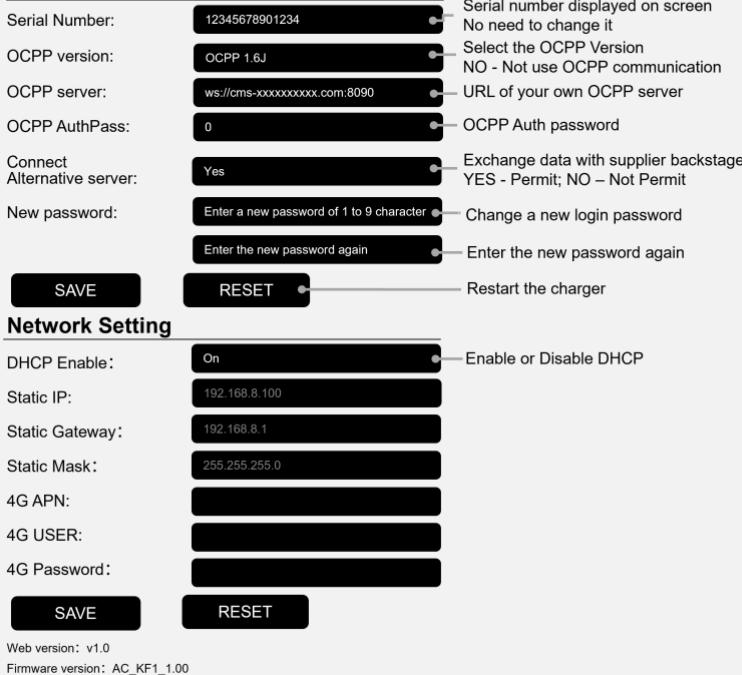
Fig. 6-8 Set parameters to config the EV charger
After setting, click the "SAVE" button to save the settings, and click the "RESET" button to restart charger for settings take effect. Enter your WiFi name and password in the page. After it takes effect, the charger can access Internet via your WiFi.
6.3.2 Config parameters Via touch screen
Step 1: Enter login interface
Click on the upper right corner area of the screen to enter the login interface.
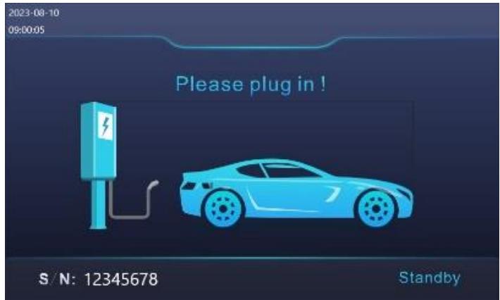
Fig. 6-9 Enter Login interface
Step 2: Login to setting
It is defaulting no password to enter the setting interface.
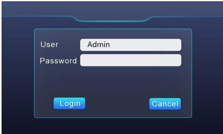
Fig. 6-10 Login setting interface
Step 3: Check information
In the info interface, can view charging information, including voltage, current, power, power consumption, etc.

Fig. 6-11 Info interface
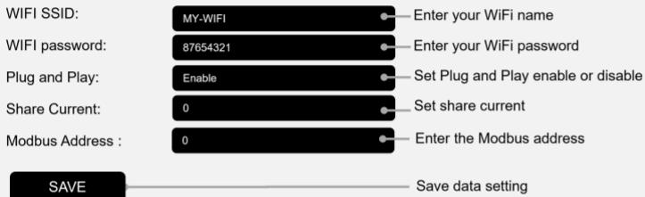
Step 4: Config your EV Charging station
Set parameters to config the EV charger on config interface. Vision only supports WIFI signals in the 2.4GHz frequency band.
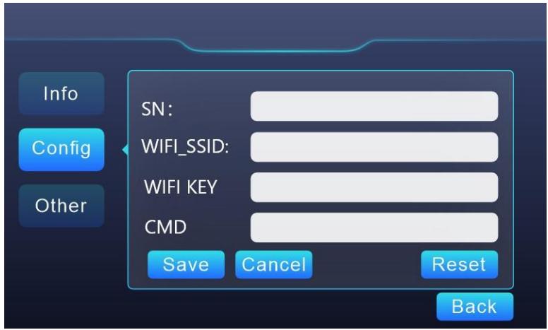
Fig. 6-12 Set parameters to config the EV charger
6.4. Start Charging
Park your EV into place, turn off, and put the EV under braking.
Pick off the charging connector form empty socket of EV charger.
As shown in Fig.6-13, plug the charging connector into the AC charging socket of the EV.

Fig. 6-13 Plug into EV socket
For the charging control mode of "Plug-and-Play" the charging will start automatically after EV connector plug in.
For the charging control mode of "Card-controlled" or "APP-controlled", you can control charging process by swipe RFID card or APP after charging connector plug in.

If you want to scan QR code on the screen to start charging, please download and install the WE E-Charge APP on your smart phone.

WE E-Charge
For Android phone, search "WE E-Charge" in Google Play Store or scan the QR code on the right to install APP.

GET IT ON Google Play

For iPhone, search "WE E-Charge" in APP Store or scan the QR code on the right to install APP.

Download on the App Store

The user manual of APP please refer to the FAQ of APP.
6.5. Normally stop charging
The charger will automatically stop when the electric vehicle is fully charged.
For the charging control mode of "Plug-and-Play", press the unlock button of the remote key of the electric vehicle, the vehicle will stop charging (requires the support of the electric car), the charging will stop automatically.
For the charging control mode of "Card-controlled", you can stop charging by swipe your RFID card again, when EV is in charging.
For the charging control mode of "APP-controlled", click the stop button on your APP, the charging will stop.
When the charging is end, please unplug the charging plug and plug into the empty socket.
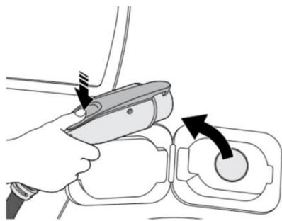
Fig. 6-14 Unplug the charging plug
6.6. Abnormally stop charging
Forced fault stop: A fault stop initiated by the onboard charger of vehicle.
Automatic fault stop: A fault stop initiated by the charger.
7. FAULT HANDLING AND MAINTENANCE
7.1. Fault Handling
The charger is automatically protected in the event of the fault. The fault information and handling methods are as follows.
| Fault code | Handling method |
| Fault code 11: CP voltage anomaly | ·Check the connection of charging plug and socket. ·Disconnect and reconnect the charging plug. |
| Fault code 13: Undervoltage input | ·Check whether input plug is reliably connected. ·Check whether the input voltage is abnormal. |
| Fault code 14: Overvoltage input | ·Check whether the input voltage is abnormal. |
| Fault code 15: Over-temperature protection | ·Check whether the charger is covered or installed in a high temperature environment. |
| Fault code 16: Metering fault | ·Power off and restart the device. |
| Fault code 17: Leakage protection | ·Check whether the charging plug, charging cable and EV socket are damaged or wet. ·Power off, disconnect and reconnect the charging plug and restart. |
| Fault code 18: Output shortage | ·Check whether the charging plug and its cables are damaged or wet. |
| Fault code 19: Output overcurrent | ·Check whether the charging connector is correctly connected. ·Check whether the OBC is normal. ·Check the set of output maximum current. |
| Fault code 23: Relay sticking | ● The device is damaged and needs to be returned to the factory for repair. |
| Fault code 24: CCID sensor fault | ● The sensor is damaged and needs to be returned to the factory for repair. |
| Fault code 25: Ground fault | ● Charger is not grounded; input power socket and input plug need to be checked. |
7.2. Maintenance
To ensure the long-term stable operation of the equipment, please maintain the equipment regularly (usually every month) according to the operating environment.
a) The equipment is maintained by professionals.
b) Check whether the equipment is well grounded and safe.
c) Check whether there are potential safety hazards around the charging pile, such as whether there are high temperature, corrosion or inflammable and explosive articles close to the charger.
d) Check whether the join point of the input terminal is in good contact and whether there is any abnormality. Check whether other terminal points are loose.
8. Moving and Storage
8.1. Moving
To avoid damage to the product, do not have severe vibration or impact during transportation.
8.2. Storage
If the product is not used immediately after purchase, and short-term or long-term storage is required, the device should be stored in a dry, well-ventilated indoor place, ignoring high temperature, humidity, dust, and metal powder environments.
WARRANTY AGREEMENT
- The scope of warranty refers to the product itself.
- The warranty period is 12 months. During the warranty period, the company will repair the product free of charge in case of failure or damage (determined by the company's technical personnel) under normal use.
- The starting time of warranty period is the date of product manufacture.
- Even in the warranty period, a certain maintenance fee will be charged in case of the following situations.
① Equipment failure caused by not following the user's manual.
② Equipment damage caused by fire, flood, abnormal voltage, etc.
③ Equipment damage caused by using the product for abnormal functions.
④ Equipment damage caused by foreign matter entering.
⑤ Equipment damage caused by other human external factors.
- The service fee shall be calculated according to the actual cost. If there is another contract, the contract shall prevail.
- Please be sure to keep this card and show it to the maintenance personnel during the warranty period.
- If you have any questions, please contact the agent or our company directly.
After sales service center
For Both FCC & IC application:
This device complies with Part 15 of the FCC Rules / Industry Canada licence-exempt
RSS standard(s). Operation is subject to the following two conditions: (1) this device may not cause harmful interference, and (2) this device must accept any interference received, including interference that may cause undesired operation.
Changes or modifications not expressly approved by the party responsible for compliance could void the user's authority to operate the equipment.
This equipment has been tested and found to comply with the limits for a Class B digital device, pursuant to part 15 of the FCC Rules. These limits are designed to provide reasonable protection against harmful interference in a residential installation. This equipment generates uses and can radiate radio frequency energy and, if not installed and used in accordance with the instructions, may cause harmful interference
to radio communications. However, there is no guarantee that interference will not occur in a particular installation. If this equipment does cause harmful interference to radio or television reception, which can be determined by turning the equipment off and on, the user is encouraged to try to correct the interference by one or more of the following measures:
—Reorient or relocate the receiving antenna.
—Increase the separation between the equipment and receiver.
Connect the equipment into an outlet on a circuit different from that
to which the receiver is connected.
—Consult the dealer or an experienced radio/TV technician for help.
MPE Requirements
To satisfy FCC / IC RF exposure requirements, a separation distance of 20 cm or more should be maintained between the antenna of this device and persons during device operation.
To ensure compliance, operations at closer than this distance is not recommended.
We provide customers with all-round technical support.
Any change or upgrade without prior notice!