K120 - Laptop Getac - Free user manual and instructions
Find the device manual for free K120 Getac in PDF.
User questions about K120 Getac
0 question about this device. Answer the ones you know or ask your own.
Ask a new question about this device
Download the instructions for your Laptop in PDF format for free! Find your manual K120 - Getac and take your electronic device back in hand. On this page are published all the documents necessary for the use of your device. K120 by Getac.
USER MANUAL K120 Getac
The Bluetooth® word mark and logos are registered trademarks owned by Bluetooth SIG, Inc.
Thunderbolt is a trademark of Intel Corporation or its subsidiaries.
All brand and product names are trademarks or registered trademarks of their respective companies.
Disclaimer
Specifications and manuals are subject to change without notice. Getac assumes no liability for damage incurred directly or indirectly from errors, omissions, or discrepancies between the device and the manuals.
Note
For the latest version of the manual, please visit the Getac website at www.getac.com.
Table of Contents
Chapter 1 Getting Started. 1
Getting the Computer Running 2
Unpacking 2
Installing the Battery Packs 3
Installing the Micro-SIM Card (Optional) 4
Using the Tether 5
Connecting to AC Power 6
Turning On and Off the Computer 8
Identifying Hardware Components 9
Tablet Components 9
Keyboard Dock Components (Optional) 16
Multiple Usage Modes 21
Changing Usage Modes 22
Opening and Closing the Display 24
Chapter 2 Operating Your Computer 25
Navigating on the Screen 26
Using the Touchscreen 26
Using the Dual Mode Display (Optional) 29
Using the Keyboard Dock 30
Using the Keyboard 30
Using the Touchpad 34
Using Network and Wireless Connections 36
Using the LAN 36
Using the WLAN. 37
Using the Bluetooth Feature 38
Using the WWAN Feature (Optional) 39
Chapter 3 Managing Power 40
AC Adapter 41
Battery Pack. 42
Charging the Battery Pack 42
Initializing the Battery Pack 43
Checking the Battery Level 43
Battery Low Signals and Actions. 44
Replacing the Battery Pack 45
Power-Saving Tips 47
Chapter 4 Using Options and Peripherals 48
Using the Fingerprint Scanner (Optional) 49
Enrolling a Fingerprint 49
Fingerprint Login 50
Using the Barcode Reader (Optional) 51
Notes 52
Connecting Peripheral Devices 53
Connecting a Display Monitor 53
Connecting a USB Device 54
Connecting a ThunderboltTM Device 54
Connecting a Device for USB Charging 55
Connecting a Serial Device 56
Connecting an Audio Device. 57
Using Various Card Readers 58
Using Smart Cards (Optional) 58
Using the NFC/RFID Reader (Optional) 59
Changing or Replacing 60
Replacing the SSD 60
Chapter 5 Using BIOS Setup 62
When and How to Use 63
Menu Descriptions 64
Information Menu 64
Main Menu 64
Advanced Menu 64
Security Menu 66
Boot Menu. 67
Exit Menu 68
Chapter 6 Using Getac Software 69
OSD Control Panel 70
G-Manager 71
G-Camera 72
Chapter 7 Care and Maintenance. 73
Protecting the Computer 74
Using an Anti-Virus Strategy 74
Using the Cable Lock 74
Taking Care of the Computer 75
Location Guidelines 75
General Guidelines 75
Cleaning Guidelines 76
Battery Pack Guidelines 76
Touchscreen Guidelines 78
When Traveling 79
Chapter 8 Troubleshooting 80
Preliminary Checklist. 81
Solving Common Problems 82
Battery Problems 82
Bluetooth Problems 82
Display Problems 83
Fingerprint Scanner Problems 84
Hardware Device Problems 84
Keyboard and Touchpad Problems 84
LAN Problems 85
Power Management Problems. 85
Software Problems. 86
Sound Problems 86
Startup Problems 87
WLAN Problems 87
Other Problems 88
Resetting the Computer 90
System Recovery 91
Using Windows RE 91
Using Recovery Partition 92
Using the Driver Disc (Optional) 93
Appendix A Specifications 94
Tablet Specifications 95
Keyboard Dock Specifications 97
Appendix B Regulatory Information 98
Safety Notices 99
About the Battery 99
About the AC Adapter 101
Heat Related Concerns 102
North America. 103
USA 103
Canada 106
User Notification of Take-back Service 108
Europe Marking and Compliance Notices. 109
Statements of Compliance 109
Restriction of Hazardous Substances (RoHS) Directive... 111
About K120-Ex 112
Special Conditions for Safe Use 112
Anti-Explosion Protective Covers 112
Use of Accessories 113
ENERGY STAR 114
About Battery and External Enclosure Replacement 115
Battery 115
External Enclosure 115
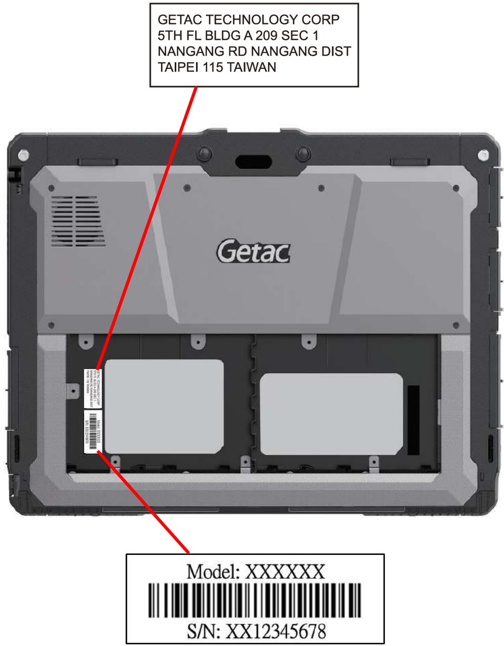
Manufacture Date and Labels. 119
Chapter 1
Getting Started
This chapter first tells you step by step how to get the computer up and running. Then, you will find a section briefly introducing the external components of the computer.
CAUTION: Safety instructions are provided in related sections throughout the User Manual. Please read the manual and any accompanying document(s) before starting to use the product.
Getting the Computer Running
Unpacking
After unpacking the shipping carton, you should find these standard items:
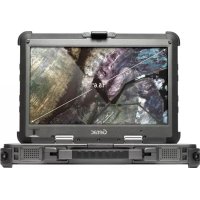
K120 Tablet
- Keyboard Dock (optional)
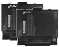
- Battery pack x 2

-or-
High-capacity battery pack x 2
- Document(s)
-
Driver disc (optional)
-
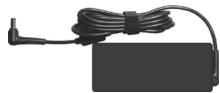
AC adapter
- AC power cord
Stylus
Tether

- Screen cleaning cloth
Inspect all the items. If any item is damage or missing, notify your dealer immediately.
NOTE: Specific models do not have the AC adapter and power cord as standard items. To purchase the AC adapter kit for your model, contact a Getac authorized distributor. (Check https://www.getac.com/en/contact/ for contact information.)
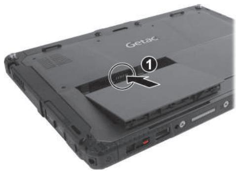
Installing the Battery Packs
K120 has two battery compartments for two battery packs; each is installed in the same way.
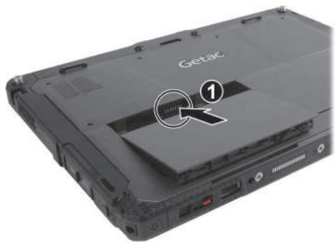
- With the battery pack correctly oriented, attach its connector side to the battery compartment at an angle (①) and then press down the other side (②). The battery release latch should automatically engage.
NOTE: If you have the high-capacity battery model, the battery pack looks different from the one shown here. The removal and installation method is the same.
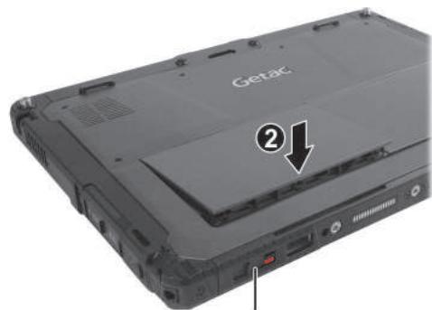
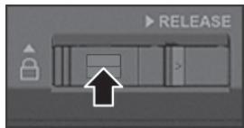
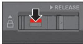
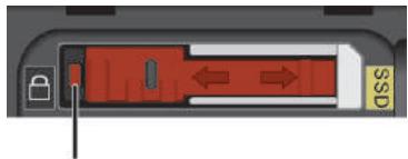
Battery release latch
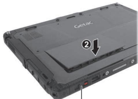
- Slide the lock of the battery release latch downward to the locked position.
CAUTION: Make sure the latch is correctly locked, not revealing the underneath red part.

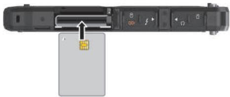
Installing the Micro-SIM Card (Optional)
- Locate the micro-SIM card slot. Slide the protective cover to the unlocked position and open the cover.
- Remove one screw to detach the small metal plate that covers the micro-SIM card slot.
- Noting the orientation, insert the micro-SIM card all the way into the slot.
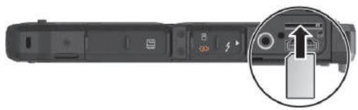
NOTE: To remove the micro-SIM card, just push in the card to release it and then pull it out.
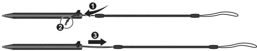
Using the Tether
A tether is provided for attaching the stylus to your Tablet.
- Thread one of the tether's loop through the hole of the stylus (①), tie a dead knot at the end (②), and pull the tether (③) so that the knot fills in the hole and prevents the tether from falling off.
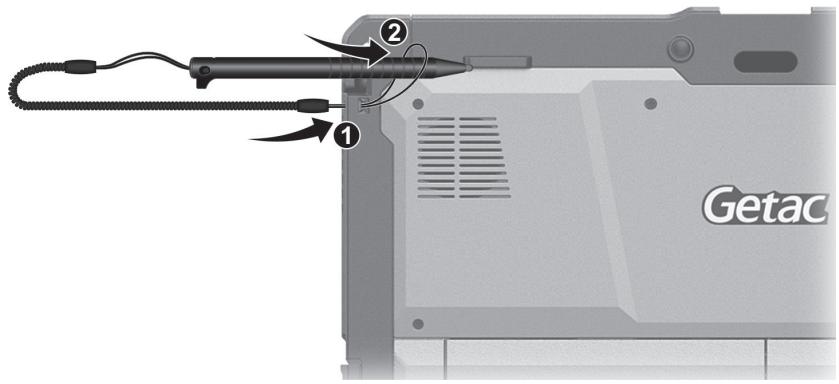
- Insert the other loop to the tether hole on the Tablet (1). Then, insert the stylus through the loop (2) and pull it tight.
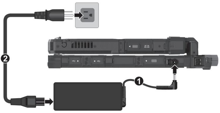
Connecting to AC Power
CAUTION: Use only the AC adapter included with your computer. Using other AC adapters may damage the computer.
NOTE:
- The battery pack is shipped to you in power saving mode that protects it from charging/discharging. It will get out of the mode to be ready for use when you install the battery pack and connect AC power to the computer for the very first time.
- When the AC adapter is connected, it also charges the battery pack. For information on using battery power, see Chapter 3.
- The power cord type varies with countries. The look of your power cord and electrical outlet might not match the one shown in this document.
You must use AC power when starting up the computer for the very first time.
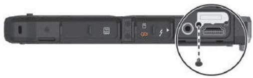
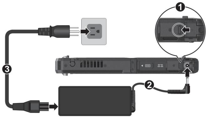
1. Tablet Only:
Open the cover of the power connector. The cover is protected by a security lock. Slide the lock outward (1) to unlock the cover.
Plug the DC cord of the AC adapter to the power connector (2).
Plug the female end of the AC power cord to the AC adapter and the male end to an electrical outlet (3).
Tablet + Keyboard Dock:
Open the cover of the power connector.
Plug the DC cord of the AC adapter to the power connector (1).
Plug the female end of the AC power cord to the AC adapter and the male end to an electrical outlet (2).
NOTE: See "Attaching the Keyboard Dock" to know how to attach the dock to K120.
- Power is being supplied from the electrical outlet to the AC adapter and onto your computer. Now, you are ready to turn on the computer.
Turning On and Off the Computer
Turning On
Press the power button ( ) for at least 2 seconds until the Power Indicator lights up. The Windows operating system should start.
NOTE:
- By default, there is 2-second delay time for the power button. You can change the setting with the "Power Button Delay" item in the BIOS Setup Utility. (See "Advanced Menu in Chapter 5.)
- Tapping the screen during startup may invoke a pre-boot menu (unless the default settings have been changed). If the menu appears, simply select Continue.
Turning Off
When you finish a working session, you can stop the system by turning off the power or leaving it in Sleep or Hibernation mode:
| To... | Do this... |
| Power off(Shutdown) | Select Start → Power → Shut down. |
| Sleep | Use one of these methods: • Press the power button.* • Select Start → Power → Sleep. |
| With the Keyboard Dock: • Close the top cover.* • Press Fn + F12.* | |
| Hibernate | By default, this option is not shown in the Start menu. If you want to use the feature, set up accordingly in Windows settings. |
- "Sleep" is the default result of the action. You can change what the action does through Windows settings.
Identifying Hardware Components
NOTE: Depending on the model you purchased, the appearance of your computer may not be exactly the same as those shown in this manual.
CAUTION: You need to open the protective covers to access the connectors. When not using a connector, make sure to close the cover completely for water- and dust-proof integrity. (Engage the locking mechanism if existing.)
Tablet Components
Front Components

| Ref | Component | Description | |
| 1 | Camera cover | Covers the camera lens. Slide the cover to open or close it. The cover provides privacy protection. | |
| Ref | Component | Description | |
| CAUTION: When using the internal microphone, make sure the camera cover is fully closed or opened. An in-between position can interfere with the microphone function. | |||
| 2 | Microphone | Receives sound and voice to record voice. | |
| 3 | Camera indicator | Lights up when the camera is in use. | |
| 4 | IR sensor (optional) | Detects the infrared energy of objects to form an image. The sensor flashes red light when in use. The near infrared (IR) imaging capability allows you to use Windows Hello face authentication. | |
| 5 | Camera lens | Allows you to use the camera function. | |
| 6 | Light sensor | Detects the surrounding lighting condition for automatic adjustment of the LCD brightness. | |
| 7 | Touchscreen | Displays and receives information for the computer. | |
| 8 | P2 button | The default function is Camera or Barcode Trigger depending on your model. | |
| Camera | Starts the G-Camera application. | ||
| Barcode Trigger | Serves as the trigger button for the barcode reader if your model has the module. | ||
| 9 | Stereo speaker | Sends out sound and voice from your computer. | |
| 10 | Power button | Turns the power on or off. (The default "off" state is "Sleep mode.") With a default setting of 2-second delay, you have to press the button for at least 2 seconds for it to function. | |
| 11 | Indicators | ||
| Power | Lights blue when the power is on. | ||
| Blinks blue when the system is in Sleep mode. | |||
| Battery | Lights amber when the battery is being charged. | ||
| Lights green when battery charging is completed. | |||
| Ref | Component | Description |
| Blinks green to indicate the battery's built-in high temperature protection mechanism is activated. CAUTION: Do not remove the battery during this period. | ||
| Blinks red (once per second) when the battery's capacity is below 10%. | ||
| Blinks red rapidly (once per 0.5 second) when there is a thermal protection problem. Ask for repair service in case this happens. | ||
| Blinks amber when the battery charging is in an abnormal state. Replace the battery in case this happens. | ||
| RF (Radio Frequency) | Lights blue when the RF radio of any RF feature (WLAN/Bluetooth/WWAN) is on. | |
| 12 | Windows logo button | Opens or closes the Start menu. |
| 13 | Plus button | Increases the sound volume. |
| 14 | Minus button | Decreases the sound volume. |
| 15 | P1 button | Opens or closes the OSD Control Panel. |
| When pressed longer: Serves as the Ctrl+Alt+Del keyboard keys. | ||
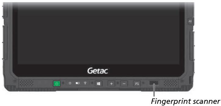
| 16 | Fingerprint scanner (optional) | Serves as the fingerprint verification, preventing unauthorized access to your computer. |
NOTE: The hardware buttons (except the power button) can be re-defined using G-Manager.
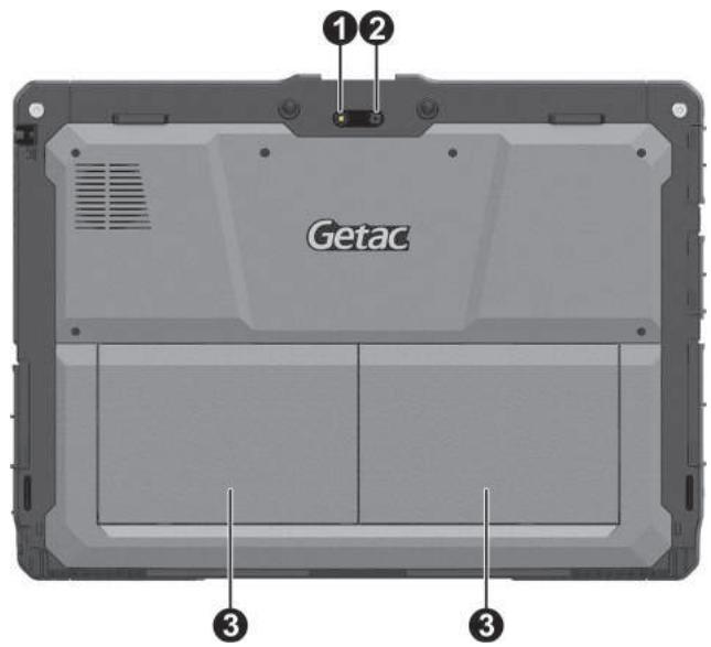
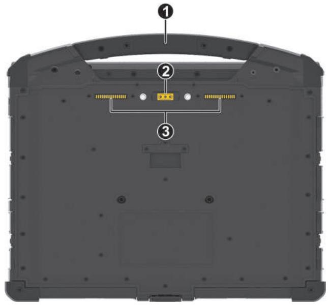
Rear Components
| Ref | Component | Description |
| ① | Flash | Provides extra light when taking pictures. |
| ② | Camera lens | Allows you to use the camera function. When the camera lens is in use, the indicator beside it lights up. |
| ③ | Battery pack | Supplies power to your computer when external power is not connected. NOTE: If you have the high-capacity battery model, the battery pack looks different from the one shown here. |
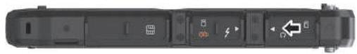
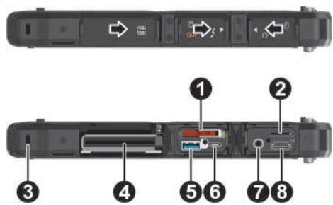
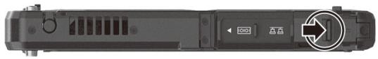
Right-Side Components
For covers with an arrowhead icon, push the cover toward one side to unlock and the other side to lock. The arrowhead points to the side for unlocking.

| Ref | Component | Description |
| 1 | Stylus holder | Holds the stylus. |
| 2 | NFC/RFID reader (optional) | Reads data from NFC/RFID tags. |
| 3 | Depending on the model, the component can be one of the following: | |
| None | ||
| USB 2.0 port | Connects a USB device. | |
| RS-232 serial connector | Connects a serial device. | |
| 4 | RJ45 connector | Connects the LAN cable. |
| 5 | Security lock | Locks the cover of the power connector. |
| 6 | Power connector | Connects the AC adapter. |
Left-Side Components
For covers with an arrowhead icon, push the cover toward one side to unlock and the other side to lock. The arrowhead points to the side for unlocking.
| Ref | Component | Description |
| ① | SSD canister | Contains the solid-state drive, which is the mass storage device of your computer. CAUTION: This device is not hot-swappable. Do not remove it without turning off the system first. |
| ② | Micro-SIM card slot (optional) | Accepts a micro-SIM card for models having the WWAN module. NOTE: The slot still exists but cannot be used for models without the WWAN module. |
| ③ | Kensington lock | Locks the computer to a stationary object for security. |
| ④ | Smart card reader (optional) | Accepts a smart card for additional security feature. |
| ⑤ | PowerShare USB port | Provides either of the below two functions depending on your setting. |
| Charges a connected mobile device. | ||
| - or - | ||
| Functions as a standard USB 3.2 Gen 1 port (default setting). | ||
| ⑥ | USB-C Thunderbolt™ 4 port | Connects to devices that support Thunderbolt or USB-C connection. |
| 7 | Combo audio connector | Connects a set of headphones or external speakers with amplifier. |
| Supports a headset microphone with 4-pole TRRS 3.5mm jack. | ||
| 8 | HDMI connector | Connects a HDMI monitor or TV set. |
Top Components
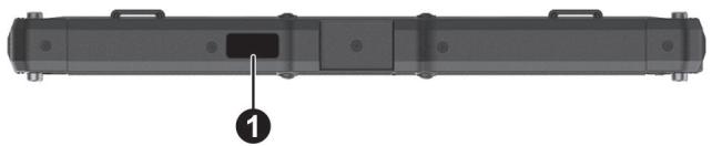
| Ref | Component | Description |
| ① | Barcode reader lens (optional) | Scans and reads barcodes. |
Bottom Components
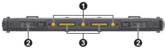
| Ref | Component | Description |
| 1 | Tri antenna passthrough | Connects to the docking station for using external WLAN/GPS/WWAN antenna. |
| 2 | Battery release latch | Releases the battery pack. The latch has a locking mechanism. Locked Unlocked |
| 3 | Docking connectors | Connect a proprietary dock such as the keyboard dock, office dock, and vehicle dock. |
Keyboard Dock Components (Optional)
NOTE:
- The Keyboard Dock can be purchased separately. Specific models come with the Keyboard Dock.
See "Multiple Usage Modes" later in this chapter for more information.
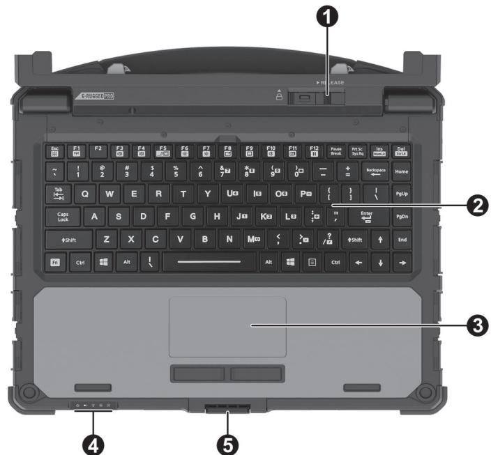
Top Components
| Ref | Component | Description |
| 1 | Tablet release latch | Releases the Tablet. The latch has a locking mechanism. |
| LOCKED | ||
| Unlocked | ||
| ② | Keyboard | Serves as the data input device of the computer. |
| ③ | Touchpad | Serves as the pointing device of the computer. |
| ④ | Indicators | |
| Power | Lights blue when the computer is on. | |
| Blinks blue when the computer is in Sleep mode. | ||
| Battery | Lights amber when the battery is being charged. | |
| Lights green when battery charging is completed. | ||
| Blinks green to indicate the battery's built-in high temperature protection mechanism is activated. CAUTION: Do not remove the battery during this period. | ||
| Blinks red (once per second) when the battery's capacity is below 10%. | ||
| Blinks red rapidly (once per 0.5 second) when there is a thermal protection problem. Ask for repair service in case this happens. | ||
| Blinks amber when the battery charging is in an abnormal state. Replace the battery in case this happens. | ||
| RF (Radio Frequency) | Lights blue when the RF radio of any RF feature (WLAN/Bluetooth/WWAN) is on. | |
| Caps Lock | Lights blue when Caps Lock is on. | |
| Num Lock | Lights blue when Num Lock is on. | |
| ⑤ | Top cover latch | Locks the Tablet and Keyboard Dock in the closed position. |
Right-Side Components
For covers with an arrowhead icon, push the cover toward one side to unlock and the other side to lock. The arrowhead points to the side for unlocking.
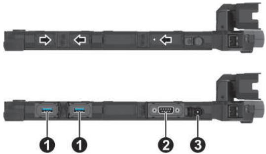
| Ref | Component | Description |
| ① | USB 3.2 port | Connects a USB device. |
| ② | RS-232 serial connector | Connects a serial device. |
| ③ | Power connector | Connects the AC adapter. |
Left-Side Components
For covers with an arrowhead icon, push the cover toward one side to unlock and the other side to lock. The arrowhead points to the side for unlocking.
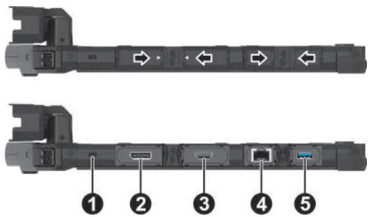
| Ref | Component | Description |
| ① | Kensington lock | Locks the Keyboard Dock to a stationary object for security. |
| ② | DisplayPort connector | Connects an external display monitor. |
| ③ | HDMI connector | Connects a HDMI monitor or TV set. |
| ④ | RJ45 connector | Connects the LAN cable. |
| ⑤ | USB 3.2 port | Connects a USB device. |
Bottom Components
| Ref | Component | Description |
| 1 | Handle | Provides a convenient way to carry the computer. The extendable handle also serves as a stabilizer for the touchscreen to hold firm when you tap on it. NOTE: When carrying the computer around, always use the handle or the carrying strap (purchased separately). |
| ② | Tri antenna passthrough | Connects to the docking station for using external WLAN/GPS/WWAN antenna. WLAN | WWAN GPS |
| ③ | Docking connector | Connects a proprietary dock such as the office dock and vehicle dock. |
Multiple Usage Modes
NOTE: The Keyboard Dock can be purchased separately. Specific models come with the Keyboard Dock.
With the Keyboard Dock, you can use K120 in different usage modes. (For information on how to change modes, see "Changing Usage Modes" later.)
| Usage Mode | Description |
| Notebook Mode | When the Tablet and Keyboard Dock are assembled, the system works as a regular notebook computer. |
| Tablet Mode | You can easily detach the Keyboard Dock and leave it behind when you desire the portability of the Tablet. |
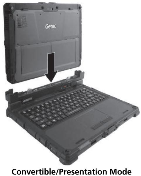
| Convertible Mode | You can transform the system from notebook to tablet and back again. For the transformation, the Tablet has to be detached, flipped over, and then reattached. NOTE: This mode is not supported if the high-capacity battery packs are installed. |
| Presentation Mode | When the screen faces outwards, you can use the Keyboard Dock as a stand for the Tablet. NOTE: This mode is not supported if the high-capacity battery packs are installed. |
Changing Usage Modes
Changing usage modes means attaching or detaching the Keyboard Dock.
Attaching the Keyboard Dock
- Make sure the cover of the power connector on K120 Tablet is closed and locked.
- Depending on the desired usage mode, have K120 Tablet face inwards or outwards.
Align and put K120 Tablet down on the holder. The release latch should click into place.
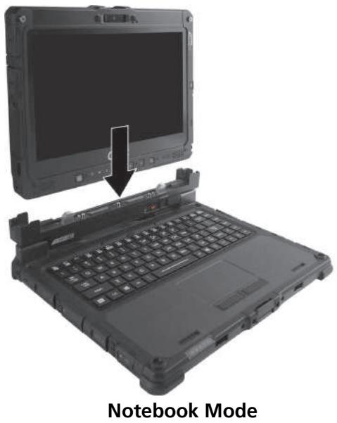
- Slide the lock of the release latch upwards to the locked position.
Detaching the Keyboard Dock
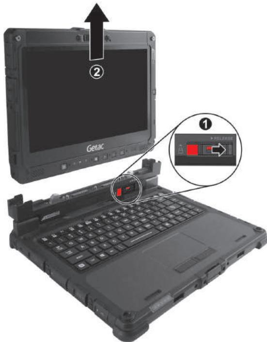
- Slide the lock of the release latch downwards to the unlocked position.
- Push the release latch toward the right, and while holding the latch (1), lift K120 Tablet out of the holder (2).
Opening and Closing the Display
To open:
- Pry open the cover latch (1).
- Lift up the display (i.e. K120 Tablet) (2). You can tilt the cover forward or backward for optimal viewing clarity.
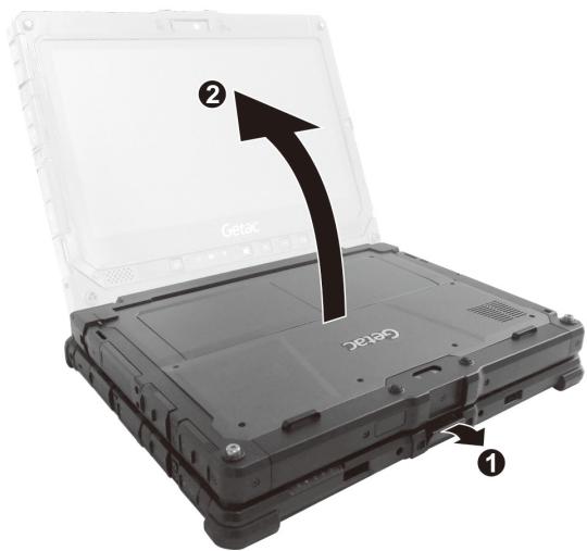
CAUTION: There is a limit to the tilting angle. Do not go beyond the limit (120 degrees).
To close:
- Close the display.
- Lift the cover latch to engage it on the display.
Chapter 2
Operating Your Computer
This chapter provides information about the use of the computer.
If you are new to computers, reading this chapter will help you learn the operating basics. If you are already a computer user, you may choose to read only the parts containing information unique to your computer.
CAUTION:
- Do not expose your skin to the computer when operating it in a very hot or cold environment.
- The computer can get uncomfortably warm when you use it in high temperatures. As a safety precaution in such a circumstance, do not place the computer on your lap or touch it with your bare hands for extended periods of time. Prolonged body contact can cause discomfort and potentially a burn.
- When K120 Tablet is placed flat on a table top for work, the back surface can get hot after long working hours. Take precautions if you need to carry K120 Tablet around while it is hot to the touch. Depending on your model, a carrying handle or strap may be available as an option. You can use the handle or strap to carry K120 Tablet.
Navigating on the Screen
The screen of your computer is touch-sensitive. You can operate the computer by touching the screen with your finger or the stylus.
CAUTION: Do not use a sharp object such as a ballpoint pen or pencil on the touchscreen. Doing so may damage the touchscreen surface.
NOTE: An optical film has been attached to the screen before shipment. The film is a consumable, which will be worn out by possible scratches. You can purchase a new one when replacement is required.
Using the Touchscreen
Your computer has a capacitive touchscreen. This type of touchscreen responds to objects that have conductive properties, such as fingertips and a capacitive-tipped stylus.
You can change the touchscreen sensitivity settings to suit your scenario. Double-tap the Touch Screen Mode shortcut on Windows desktop to open the settings menu and select one of the options (as shown below).
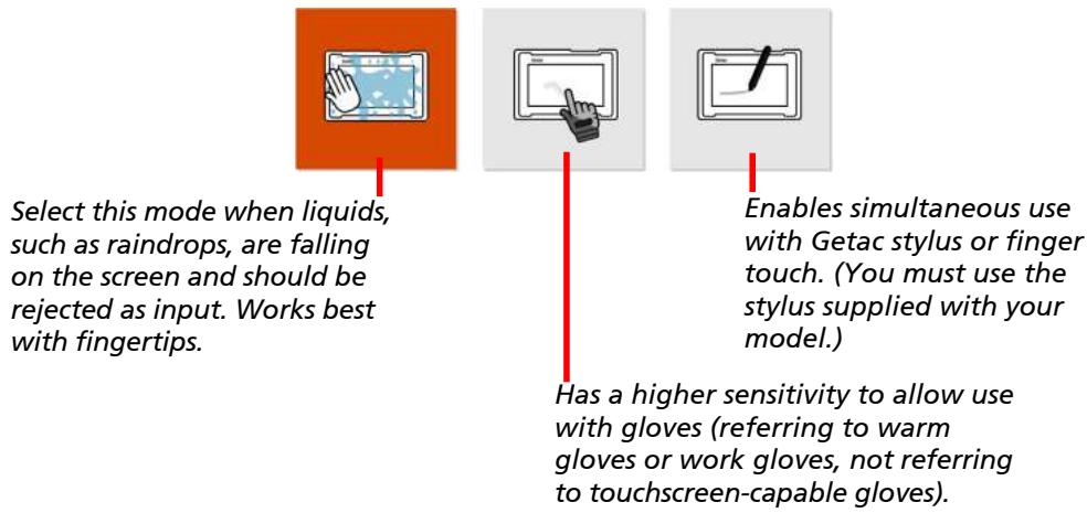
NOTE:
- In high temperatures (above 60^ / 140^ ), set the mode to Finger instead of Glove or Stylus mode.
- If liquid is spilled on the touchscreen causing a wet area, the area will stop responding to any inputs. For the area to function again, you must dry it.
The following table shows how you use the touchscreen to obtain equivalent mouse functions.
| Term/Action | Equivalent Mouse Function |
| Tap: Touch the screen once. | Click/Point |
| Double-tap: Touch the screen twice rapidly. | Double-click |
| Tap and hold: Tap and hold until a popup menu appears. | Right-click |
| Drag: Hold the stylus (or finger) on the screen and drag across the screen until reaching your destination. | Drag |
Using Multi-touch Gestures
You can interact with your computer by placing two fingers on the screen. The movement of the fingers across the screen creates "gestures," which send commands to the computer.
Here are the multi-touch gestures that you can use:
| Gestures | Actions (○=finger down; ○=finger up) | Descriptions |
| Pan (Scroll) | Drag 1 or 2 fingers up or down. | Use panning to see another part of a page that has scroll bars. |
| Zoom (Pinch) | Move two fingers apart/toward each other. | Use zooming to make an item (a photo for example) on the screen larger or smaller. The gesture works in applications that support mouse wheel zooming. |
| Rotate | or Move two fingers in opposing directions. -or- Use one finger to pivot around another. | Use rotating to move a picture or other item on the screen in a circular direction (clockwise or counter-clockwise). The gesture works in applications that support the specific gesture. |
| Press and Tap | Press on target and tap using a second finger. | Use press and tap to access the shortcut menu. |
| Two-finger Tap | Tap two fingers at the same time (where the target is in the midpoint between the fingers). | The function is defined by applications that support the specific gesture. |
| Flicks | Make quick drag gestures in the desired direction. | Flick left or right to navigate back and forward in a browser and other applications. The gesture works in most applications that support back and forward. |
Using the Dual Mode Display (Optional)
Dual mode display (if your model has the feature) incorporates both touchscreen and digitizer functions.
The display is set to Touchscreen mode by default. Touchscreen mode provides all the functionalities that an ordinary touchscreen has. When the computer receives signals from the digitizer pen, the display automatically switches to Digitizer mode.
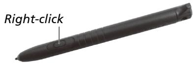
You can move the cursor by bringing the digitizer pen close to the screen, without actually touching the screen's surface. The digitizer pen has a shortcut button that functions as the right-click of a mouse.
Using the Keyboard Dock
NOTE: The Keyboard Dock can be purchased separately. Specific models come with the Keyboard Dock.
Using the Keyboard
Your keyboard has all the standard functions of a full-sized computer keyboard plus an Fn key added for specific functions.
The standard functions of the keyboard can be further divided into four major categories:
Typewriter keys
- Cursor-control keys
Numeric keys
- Function keys
Typewriter Keys
Typewriter keys are similar to the keys on a typewriter. Several keys are added such as the Ctrl, Alt, Esc, and lock keys for special purposes.
The Control (Ctrl) / Alternate (Alt) key is normally used in combination with other keys for program-specific functions. The Escape (Esc) key is usually used for stopping a process. Examples are exiting a program and canceling a command. The function depends on the program you are using.
Cursor-Control Keys
Cursor-control keys are generally used for moving and editing purposes.
NOTE: The word "cursor" refers to the indicator on the screen that lets you know exactly where on your screen anything you type will appear. It can take the form of a vertical or horizontal line, a block, or one of many other shapes.
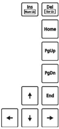
Numeric Keypad
A 15-key numeric keypad is embedded in the typewriter keys as shown next:

Numeric keys facilitate entering of numbers and calculations. When Num Lock is on, the numeric keys are activated; meaning you can use these keys to enter numerals.
NOTE:
- When the numeric keypad is activated and you need to type the English letter in the keypad area, you can turn Num Lock off or you can press Fn and then the letter without turning Num Lock off.
- Some software may not be able to use the numeric keypad on the computer. If so, use the numeric keypad on an external keyboard instead.
The Num Lock key can be disabled. (See "Main Menu" in Chapter 5.)
Function Keys
On the top row of the keys are the function keys: F1 to F12. Function keys are multi-purpose keys that perform functions defined by individual programs.
Fn Key
The Fn key, at the lower left corner of the keyboard, is used with another key to perform the alternative function of a key. To perform a desired function, first press and hold Fn, then press the other key.
Hot Keys
Hot keys refer to a combination of keys that can be pressed any time to activate special functions of the computer. Most hot keys operate in a cyclic way. Each time a hot key combination is pressed, it shifts the corresponding function to the other or next choice.
You can easily identify the hot keys with the icons imprinted on the keytop. The hot keys are described next.
| Key | Description |
| Fn Esc | Switches the keyboard backlight on and off (option). |
| F1 | Switches the RF (radio frequency) radio on and off. When off, all wireless modules (such as WLAN, Bluetooth, and WWAN) cannot be used. When on, individual settings of the module work. |
| F3 | Decreases the sound volume. |
| F4 | Increases the sound volume. |
| F5 | Switches the display output to the next choice if an external display is connected. Choices are: LCD only LCD + External display (Duplicate) LCD + External display (Extend) External display only The hot keys are equivalent to Windows logo key + P. |
| Fn F6 | Decreases the LCD brightness. |
| Fn F7 | Increases the LCD brightness. |
| Fn F8 | Switches the touchscreen on or off. |
| Fn F9 | Switches the touchpad off or on. |
| Fn F10 | Switches the system sound output off (mute) or on. |
| Fn F11 | Switches the display on or off. |
| Fn F12 | Serves as the sleep button that you can define with Windows' Power Options. |
Windows Keys
The keyboard has two keys that perform Windows-specific functions: Windows Logo key and Application key.
The Windows Logo key opens the Start menu and performs software-specific functions when used in combination with other keys. The Application key usually has the same effect as a right mouse click.
Using the Touchpad
CAUTION: Do not use a sharp object such as a pen on the touchpad. Doing so may damage the touchpad surface.
NOTE:
Press Fn+F9 to toggle the touchpad on or off.
- For optimal performance of the touchpad, keep your fingers and the pads clean and dry. When tapping on the pad, tap lightly. Do not use excessive force.
The touchpad is a pointing device that allows you to communicate with the computer by controlling the location of the pointer on the screen and making selection with the buttons.
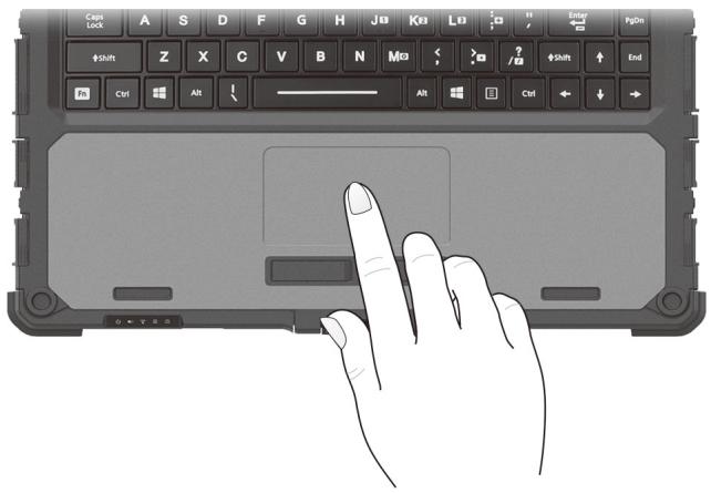
The touchpad consists of a rectangular pad (work surface) and a left and right buttons. To use the touchpad, place your forefinger or thumb on the pad. The rectangular pad acts like a miniature duplicate of your display. As you slide your fingertip across the pad, the pointer (also called cursor) on the screen moves accordingly. When your finger reaches the edge of the pad, simply relocate yourself by lifting the finger and placing it on the other side of the pad.
Here are some common terms that you should know when using the touchpad:
| Term | Action |
| Point | Move your finger on the pad until the cursor points to the selection on the screen. |
| Click | Press and release the left button. -or- Tap gently anywhere on the pad. |
| Double-click | Press and release the left button twice in quick succession. -or- Tap twice on the pad rapidly. |
| Drag and drop | Press and hold the left button, then move your finger until you reach your destination (drag). Finally, release the button (drop) when you finish dragging your selection to the destination. The object will drop into the new location. -or- Gently tap twice on the pad and on the second tap, keep your finger in contact with the pad. Then, move your finger across the pad to drag the selected object to your destination. When you lift your finger from the pad, the selected object will drop into place. |
Configuring the Touchpad
You may want to configure the touchpad to suit your needs. For example, if you are a left-handed user, you can swap the two buttons so that you can use the right button as the left button and vice versa. You can also change the size of the on-screen pointer, the speed of the pointer, and so on.
To configure the touchpad, go to Settings Devices Touchpad (for Windows 10) or Settings Bluetooth & devices Touchpad (for Windows 11).
Using Network and Wireless Connections
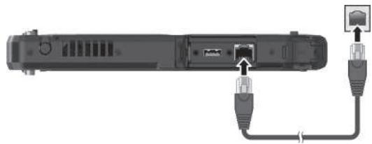
Using the LAN
To connect the network cable to the LAN module, connect one end of the LAN cable to the RJ45 connector on the computer and the other end to the network hub.
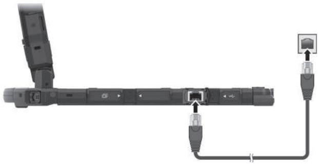
If you have the Keyboard Dock:
Using the WLAN
The WLAN (Wireless Local Area Network) module of your computer supports IEEE 802.11 ax.
Turning On/Off the WLAN Radio
To turn on the WLAN radio:
Select the network icon in the lower right of the taskbar. Then, select the Wi-Fi button.
To turn off the WLAN radio:
You can turn off the WLAN radio the same way you turn it on.
If you want to quickly turn off all wireless radio, simply switch on Airplane mode. You can control the Airplane mode using one of the below methods.
- Select the network icon in the lower right of the taskbar. Then, select the Airplane mode button.
- Use the Airplane Mode button in the OSD Control Panel.
- Press Fn+F1 (if the Keyboard Dock is connected).
Connecting to a WLAN Network
- Make sure that the WLAN function is enabled (as described above).
- Select the network icon in the lower right of the taskbar.
- Select the device you want to connect from the search results.
- Some networks require a network security key or passphrase. To connect to one of those networks, ask your network administrator or Internet service provider (ISP) for the security key or passphrase.
For more information on setting a wireless network connection, refer to Windows online help.
Using the Bluetooth Feature
The Bluetooth technology allows short-range wireless communications between devices without requiring a cable connection. Data can be transmitted through walls, pockets and briefcases as long as two devices are within range.
Turning On/Off the Bluetooth Radio
To turn on the Bluetooth radio:
Go to Settings Devices Bluetooth & other devices (for Windows 10) or Settings Bluetooth & devices (for Windows 11). Slide the Bluetooth switch to the On position.
To turn off the Bluetooth radio:
You can turn off the Bluetooth radio the same way you turn it on.
If you want to quickly turn off all wireless radio, simply switch on Airplane mode. You can control the Airplane mode using one of the below methods.
- Select the network icon in the lower right of the taskbar. Then, select the Airplane mode button.
- Use the Airplane Mode button in the OSD Control Panel.
- Press Fn+F1 (if the Keyboard Dock is connected).
Connecting to another Bluetooth Device
- Make sure that the Bluetooth function is enabled (as described above).
- Make sure that the target Bluetooth device is turned on, discoverable and within close range. (See the documentation that came with the Bluetooth device.)
- Windows 10: Go to Settings Devices Bluetooth & other devices Add Bluetooth or other device Bluetooth.
Windows 11: Go to Settings Bluetooth & devices Add device Bluetooth.
- Select the device you want to connect from the search results.
- Depending on the type of Bluetooth device that you want to connect to, you will need to enter the pertinent information.
For detailed information on using the Bluetooth feature, see Windows' online Help.
Using the WWAN Feature (Optional)
A WWAN (Wireless Wide Area Network) uses mobile telecommunication cellular network technologies to transfer data. The WWAN module of your computer supports 3G and 4G LTE.
NOTE:
- Your model only supports data transmission. Voice transmission is not supported.
- For instructions on installing the micro-SIM card, see "Installing the Micro-SIM Card (Optional)" in Chapter 1.
Turning On/Off the WWAN Radio
To turn on the WWAN radio:
Select the network icon in the lower right of the taskbar. Then, select the Cellular button.
To turn off the WWAN radio:
You can turn off the WWAN radio the same way you turn it on.
If you want to quickly turn off all wireless radio, simply switch on Airplane mode. You can control the Airplane mode using one of the below methods.
- Select the network icon in the lower right of the taskbar. Then, select the Airplane mode button.
- Use the Airplane Mode button in the OSD Control Panel.
- Press Fn+F1 (if the Keyboard Dock is connected).
Setting up a WWAN Connection
Go to Settings Network & Internet Cellular. (For detailed information on cellular settings in Windows, see Microsoft Support website.)
NOTE: When using the LTE GPS tracking function, make sure that the SIM card is inserted and the mobile network is enabled.
Chapter 3
Managing Power
Your computer operates either on external AC power or on internal battery power.
This chapter tells you how you can effectively manage power. To maintain optimal battery performance, it is important that you use the battery in the proper way.
AC Adapter
CAUTION:
- The AC adapter is designed for use with your computer only. Connecting the AC adapter to another device can damage the adapter.
- The AC power cord supplied with your computer is for use in the country where you purchased your computer. If you plan to go overseas with the computer, consult your dealer for the appropriate power cord.
- When you disconnect the AC adapter, disconnect from the electrical outlet first and then from the computer. A reverse procedure may damage the AC adapter or computer.
- When unplugging the connector, always hold the plug head. Never pull on the cord.
The AC adapter serves as a converter from AC (Alternating Current) to DC (Direct Current) power because your computer runs on DC power, but an electrical outlet usually provides AC power. It also charges the battery pack when connected to AC power.
The adapter operates on any voltage in the range of 100 V - 240 V AC.
Battery Pack
Your computer has two battery packs. The battery pack is the internal power source for the computer. It is rechargeable using the AC adapter.
CAUTION: Always keep both battery packs installed, especially when the computer is running on battery power. A battery pack can be removed only when it is not being charged/discharged or if you are hot-swapping the battery pack.
Charging the Battery Pack
NOTE:
- Charging will not start if the battery's temperature is outside the allowed range, which is between 0^ ( 32^ ) and 50^ ( 122^ ). Once the temperature meets the requirements, charging automatically resumes.
- During charging, do not disconnect the AC adapter before the battery has been fully charged; otherwise you will get a prematurely charged battery.
- The battery has a high temperature protection mechanism which limits the maximum charge of the battery to 80% of its total capacity in the event of high temperature conditions. In such conditions, the battery will be regarded as fully charged at 80% capacity.
- The battery level may automatically lessen due to the self-discharge process, even when the battery pack is fully charged. This happens no matter if the battery pack is installed in the computer.
To charge the battery pack, connect the AC adapter to the computer and an electrical outlet. The Battery Indicator ( ) on the computer glows amber to indicate that charging is in progress. You are advised to keep the computer power off while the battery is being charged. When the battery is fully charged, the Battery Charge Indicator glows green.
The two battery packs are charged in parallel. It takes approximately 5 hours to fully charge the two battery packs when the power is off and approximately 6 hours when the power is on (may need a longer charging time at lower temperatures).
CAUTION: After the computer has been fully recharged, do not immediately disconnect and reconnect the AC adapter to charge it again. Doing so may damage the battery.
Initializing the Battery Pack
You need to initialize a new battery pack before using it for the first time or when the actual operating time of a battery pack is much less than expected. Initializing is the process of fully charging, discharging, and then charging. It can take several hours.
The G-Manager program provides a tool called "Battery Recalibration" for the purpose. (See "G-Manager" in Chapter 6.)
Checking the Battery Level
NOTE: Any battery level indication is an estimated result. The actual operating time can be different from the estimated time, depending on how you are using the computer.
The operating time of a fully charged battery pack depends on how you are using the computer. When your applications often access peripherals, you will experience a shorter operating time.
The two battery packs are discharged in parallel.
By Operating System
You can check the approximate battery level using the battery meter function of the operating system. To read the battery level in Windows, click the battery icon on the taskbar.
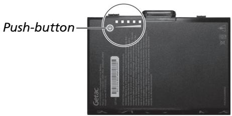
By Gas Gauge
On the exterior side of the battery pack is a gas gauge for displaying the estimated battery charge. When the battery pack is not installed in the computer and you want to know the battery charge, you can press the push-button to see the number of LEDs that light up. Each LED represents 20% charge.
Battery Low Signals and Actions
The battery icon changes appearance to display the current state of the battery.
| Battery Icon | Battery Level | Description |
| Discharging | The icon shows the charge remaining in 10-percent increments until the charge reaches the low-battery level. | |
| Low | The battery charge has reached the low-battery level. | |
| Critically low | The battery charge has reached the critical battery level. By default, Windows will display a notification and put your computer into Hibernation. |
When the battery is low, the computer's Battery Indicator (▶) also blinks red to alert you to take actions.
Always respond to low-battery by connecting the AC adapter, placing your computer in Hibernation mode, or turning off the computer.
Replacing the Battery Pack
CAUTION:
- There is danger of explosion if the battery is incorrectly replaced. Replace the battery only with the computer manufacturer's battery packs. Discard used batteries according to the dealer's instructions.
- Do not attempt to disassemble the battery pack.
- A battery pack can get hot due to long working hours. Do not touch a hot battery pack with bare hands. After removing a battery pack, put it in a well-ventilated area.
NOTE:
- You can hot swap one battery pack while the other one is supplying the power. The appropriate temperature range for hot swapping the battery pack is between -21^ (-5.8°F) and 45^ (113°F).
- If you have the high-capacity battery model, the battery pack looks different from the one shown here. The removal and installation method is the same.
To replace the battery pack, follow these steps:
- If the Keyboard Dock is connected, detach it. (See "Detaching the Keyboard Dock" in Chapter 1 for instructions.)
- Skip this step if you are hot swapping the battery pack.
Turn off the Tablet PC and disconnect the AC adapter. After turning off the computer, allow a cool-down time of at least 5 minutes before removing the battery pack.
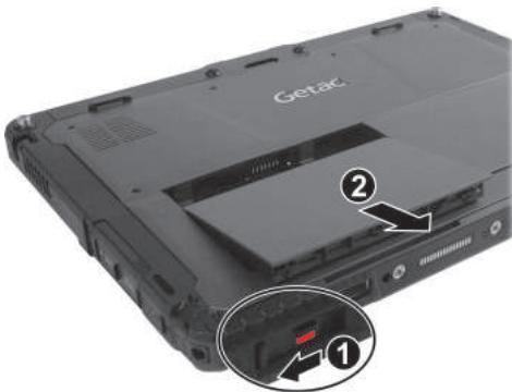
- Slide the lock of the battery release latch upwards to the unlocked position.
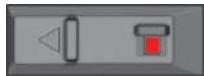
- Slide the battery release latch toward the left (①). The battery pack will slightly pop up. Remove the battery pack from its compartment (②).
- Fit another battery pack into place. With the battery pack correctly oriented, attach its connector side to the battery compartment at an angle (1) and then press down the other side (2) . The battery release latch should automatically engage.
Battery release latch
- Slide the lock of the battery release latch downward to the locked position.
CAUTION: Make sure the latch is correctly locked, not revealing the underneath red part.

Power-Saving Tips
Aside from enabling your computer's power saving mode, you can do your part to maximize the battery's operating time by following these suggestions.
- Do not disable Power Management.
- Decrease the LCD brightness to the lowest comfortable level.
- Shorten the length of time before Windows turn off the display.
- When not using a connected device, disconnect it.
- Turn off the wireless radio if you are not using the wireless module (such as WLAN, Bluetooth, or WWAN).
- Turn off the computer when you are not using it.
Chapter 4
Using Options and Peripherals
This chapter describes the use of optional modules and the connection of peripherals.
Using the Fingerprint Scanner (Optional)
CAUTION:
- For optimal performance, both the scanning surface and the finger should be clean and dry. Clean the scanning surface when needed. You can use adhesive tape to remove dirt and oil from the scanner surface.
- It is not recommended that you use the fingerprint scanner in a below-freezing temperature. The moisture on your finger can freeze to the scanner's metal surface when you touch it, resulting in a failed operation. Besides, touching freezing metal with your finger can cause frostbite.
The fingerprint scanner (if your model has the feature) provides a strong authentication mechanism based on fingerprint recognition. You can log on to Windows and dismiss the lock screen with an enrolled fingerprint instead of a password or PIN.
Enrolling a Fingerprint
NOTE: You can enroll a fingerprint only after creating a password/PIN for the Windows user account.
- Go to Settings Accounts Sign-in options.
- Select the fingerprint option.
- Follow the onscreen instructions to complete.
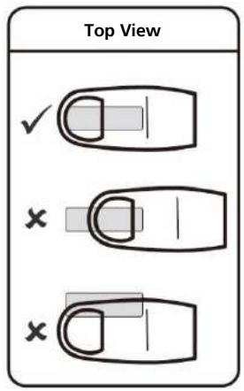
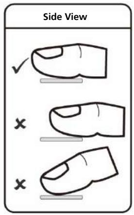
When placing your finger on the scanner, make sure you position your finger correctly as described and illustrated below.
- Maximum contact area: Place your finger to completely cover the scanner with maximum contact surface.
- Place on the center: Position the center of your fingerprint (core) at the center of scanner.
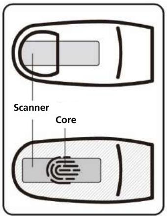
After placing your finger on the scanner, lift it up and place it down again. You should slightly move your finger between each reading. Repeat this action several times (normally between 12 and 16 times) until the fingerprint is enrolled.
Fingerprint Login
NOTE: The fingerprint login process can take a while. This is because the system has to check hardware devices and security configuration before initiating the fingerprint scanner.
With an enrolled fingerprint, the user can log on by tapping the Fingerprint option in Windows login screen and then placing the finger on the scanner. The user can also dismiss the lock screen with the fingerprint.
The fingerprint scanner has 360-degree readability. You can place your finger in any orientation for the scanner to recognize an enrolled fingerprint.
If fingerprint login attempts fail three times, you will be switched to password login.
Using the Barcode Reader (Optional)
NOTE:
- For enhanced applications and customization of the module, you can use the Barcode Manager program. (For detailed information on the program, see the program's online help.)
- The maximum operating temperature for the barcode reader is 50^ C (122°F).
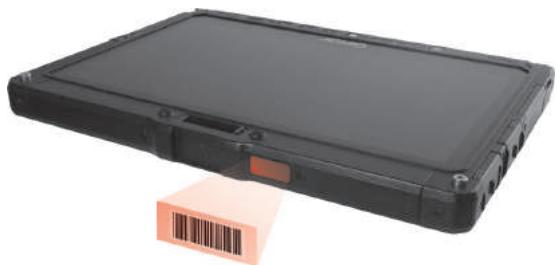
If your model has the barcode reader module, you can scan and decode most common 1D and 2D symbologies.
To read barcodes:
- Start your processing software and open a new or existing file. Place the insertion point (or called cursor) where you want the data to be entered.
- Press the Trigger button (P2) on your Tablet. (The button function is configured by G-Manager.)
- Aim the scan beam at the barcode. (The scan beam projected from the lens varies with models.)
Adjust the lens' distance from the barcode, shorter for a smaller barcode and farther for a larger one.
NOTE: Improper ambient light and scanning angle can affect the scanning results.
CAUTION: When or immediately after using the barcode scanner for a long time, do not touch the lens area as the area might be hot.
- Upon a successful scan, the system beeps and the decoded barcode data is entered.
Notes
The below label indicates that your barcode scanner supports the TraCS (Traffic and Criminal Software) trigger button. The TraCS feature is available for customized orders only. If you have already purchased a standard model and require the TraCS feature, please contact Getac technical support for the purpose.

- Pulse repetition rate: 57.67 Hz
- Scan angle: 360^ tilt; ± 60^ pitch; ± 60^ skew
CAUTION: Use of controls or adjustments or performance of procedures other than those specified herein may result in hazardous radiation exposure.
About Manufacture Date and Labels
See "Manufacture Date and Labels" in Appendix B for information.
Connecting Peripheral Devices
Connecting a Display Monitor
If you want the benefits of a larger display screen with higher resolution, you can connect an external display monitor to your computer.
The Tablet has an HDMI connector.
The Keyboard Dock has a HDMI connector and a DisplayPort connector. Depending on the type of your monitor, plug the monitor's signal connector to the HDMI or DisplayPort connector.
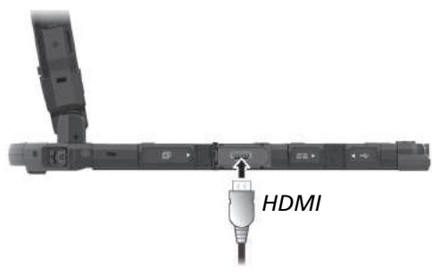
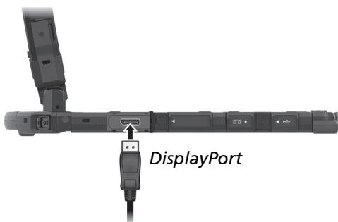
You can switch the display output by using Windows Control Panel, OSD Control Panel, or Fn+F5 (if the Keyboard Dock is connected).
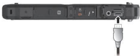
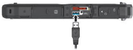
Connecting a USB Device
The Tablet has one USB 3.2 Gen 1 port and one USB 2.0 port (optional) for connecting USB devices, such as a digital camera, scanner, printer, and mouse.
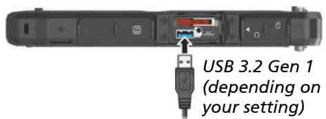
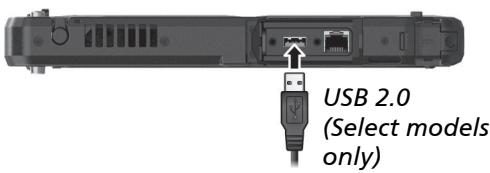
NOTE: The USB 3.2 Gen 1 port on your Tablet can also function as a PowerShare USB port when set up accordingly. (See "Connecting a Device for USB Charging" later for information.)
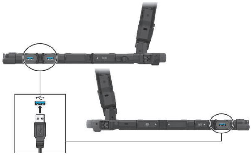
The Keyboard Dock has three USB 3.2 ports.
Connecting a Thunderbolt™ Device
The Tablet has a Thunderbolt 4 port. This port features:
- USB Type-C (or simply USB-C) connector format
Up to 40 Gbps data transfer speed -
DisplayPort
-
USB Power Delivery
Note that you should use the appropriate wattage/voltage USB-C power adapter for your computer model.
USB-C power adapter specifications: 85 W or above (20 V, 4.25 A or above)
Applications include storage, display, networking, single-cable docking, and more.
NOTE:
- When the notebook computer (i.e. Tablet + Keyboard Dock) is connected to the office dock or vehicle dock, using the USB Power Delivery function is not recommended. This is because a protection mechanism will regulate the performance under such a circumstance, resulting in limited performance.
Thunderbolt ports are backward-compatible with USB-C devices. An USB-C device plugged into a Thunderbolt port will function normally.
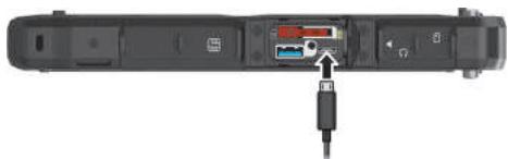
Connecting a Device for USB Charging
The Tablet supports a PowerShare USB port (F). You can use this port to charge mobile devices even when the computer is in power-off, sleep, or hibernation state.
A connected device is charged by either external power (if the AC adapter is connected) or by the computer's battery (if the AC adapter is not connected). In the latter case, charging will stop when the battery level gets low (20% capacity).
Notes and Cautions on USB Charging
- To use the USB charging feature, you must first enable the feature by running the BIOS Setup program or the G-Manager program. (See
"Advanced Menu" in Chapter 5 or "G-Manager" in Chapter 6.) Otherwise, the PowerShare USB port functions as a standard USB 3.2 Gen 1 port.
- Before connecting a device for charging, make sure the device works with the USB charging feature.
- Connect a device directly to this port. Do not connect via a USB hub.
- After resuming from sleep or hibernation, the computer may not detect the connected device. If this happens, try disconnecting and reconnecting the cable.
-
USB charging will stop in the following situations.
-
You shut down the computer by pressing the power button for more than 5 seconds
-
All power (AC adapter and battery pack) is disconnected and then reconnected during power-off state.
-
For USB devices which do not require charging, connect them to other USB ports on your computer.
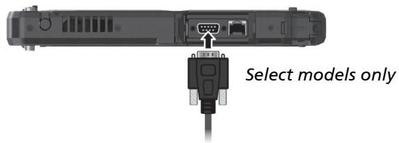
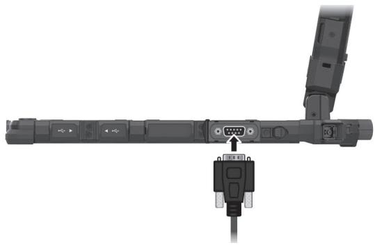
Connecting a Serial Device
Select models have a serial port for connecting a serial device such as a serial mouse or serial communication device.
The Keyboard Dock has a serial port.
Connecting an Audio Device
The combo connector is the "4-pole TRRS 3.5mm" type so you can connect a compatible headset microphone.
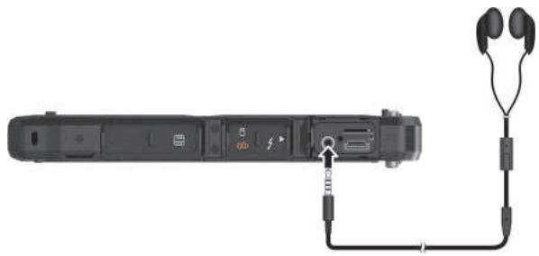
SAFETY WARNING:

To prevent possible hearing damage, do not listen at high volume levels for long periods.
Using Various Card Readers
Using Smart Cards (Optional)
With an embedded microcontroller, smart cards have the unique ability to store large amounts of data, carry out their own on-card functions (e.g., encryption and mutual authentication), and interact intelligently with a smart card reader.
To insert a smart card:
- Locate the smart card reader and open the protective cover.
- Slide the smart card, with its label and embedded computer chip facing down into the slot.
- Close the cover.
To remove a smart card:
- Make sure that the software is not accessing the smart card.
- Open the cover.
- Slightly push the card to release and then pull it out of the slot.
- Close the cover.
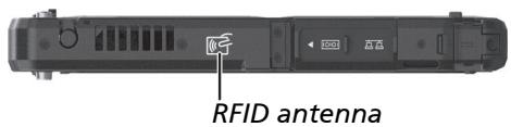
Using the NFC/RFID Reader (Optional)
If your model has the NFC/RFID reader module, you can read data from NFC (Near Field Communication) and RFID (Radio Frequency Identification) tags.
This module is enabled by default. To enable or disable the module, run the BIOS Setup program and select Advanced Device Configuration RFID Card Reader. (See Chapter 5 for information on BIOS Setup.)
For optimal results when reading an NFC/RFID tag, have the tag face the antenna in the same orientation as indicated by the icon on the exterior of the computer.
NOTE:
- When not using an NFC/RFID card, do not leave it within or near the antenna area.
- For enhanced applications and customization of the module, contact your authorized Getac dealer.
- The NFC reader requires specialized applications. For further information, ask your system administrator.
Changing or Replacing
Replacing the SSD
- Turn off the computer and disconnect the AC adapter.
- Locate the SSD canister and open its protective cover.
- Pry the plastic strip (1) to release it (2).
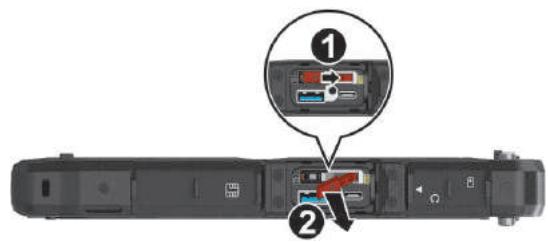
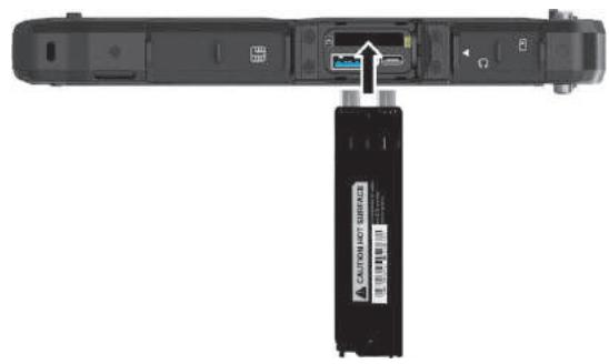
- Using the plastic strip, pull the SSD canister out of the slot.
- Noting the orientation, insert the new SSD canister all the way into the slot.
- Make sure the plastic strip is engaged. Slide the plastic strip toward the locked position ( ).
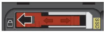
CAUTION: Make sure the plastic strip is correctly locked, not revealing the underneath red part.
Incorrect (revealing the red part)
Chapter 5
Using BIOS Setup
BIOS Setup Utility is a program for configuring the BIOS (Basic Input/ Output System) settings of the computer. BIOS is a layer of software, called firmware, that translates instructions from other layers of software into instructions that the computer hardware can understand. The BIOS settings are needed by your computer to identify the types of installed devices and establish special features.
This chapter tells you how to use the BIOS Setup Utility.
When and How to Use
NOTE:
- The actual setting items on your model may differ from those described in this chapter.
- The availability of some setting items depends on the configuration of your computer.
You need to run BIOS Setup Utility when:
- You see an error message on the screen requesting you to run BIOS Setup Utility.
- You want to restore the factory default BIOS settings.
- You want to modify some specific settings according to the hardware.
- You want to modify specific settings to optimize the system performance.
To run BIOS Setup Utility:
Method 1: During system startup when the logo screen appears, tap the screen or press the Windows Logo button on your computer. In the preboot menu that appears, select Setup Utility.
NOTE:
- If you don't want any accidental tapping to invoke the pre-boot menu, you can disable this method by setting the "Screen Tapping for Boot Options" item in the BIOS Setup Utility.
- The time period in which you can use the above method is extremely short. You can use the other method as described below.
Method 2: Go to Settings Update & security Recovery (for Windows 10) or Settings System Recovery (for Windows 11). Under Advanced startup, select Restart now. In the boot options menu, select Troubleshoot Advanced options UEFI Firmware Settings. Select Restart. In the pre-boot menu that appears, select Setup Utility.
Menu Descriptions
Information Menu
The Information menu contains the basic configuration information of the system. There are no user-definable items in this menu.
NOTE: The "Asset Tag" information appears when you have entered the asset number for this computer using the asset management program. The program is provided in the Asset tag folder of the Driver disc.
Main Menu
The Main menu contains the various system settings.
- System Date sets the system date.
- System Time sets the system time.
- Internal Numlock sets if the Num Lock function of the keyboard can work. When set to Enabled, you can press Fn + Num Lock to activate the numeric keypad, which is embedded in the typewriter keys. When set to Disabled, Num Lock does not work. In this case, you can still press Fn + a letter key to enter a number.
Advanced Menu
The Advanced menu contains the advanced settings.
- Wake Up Capability Home Button Wake Up from Sleep allows the Home button to wake up the system from Sleep mode. The Home button refers to the Windows logo button on your model.
- Power Button Delay sets power button delay time (1 second or 2 seconds) so that accidental touching of the power button does not cause undesired operation. You can also disable the delay.
-
AC Initiation sets if connecting AC power will automatically start or resume the system.
-
Screen Tapping for Boot Options sets if tapping the screen during startup will invoke the boot options menu which provides access to some pre-boot operations. If disabled, tapping the screen during startup has no effect to the system's booting process.
- USB Power-off Charging enables or disables the USB charging feature of the PowerShare USB port. When disabled, the PowerShare USB port functions as a standard USB port. For detailed information on the PowerShare USB port, see "Connecting a Device for USB Charging" in Chapter 4.
- Magnetic Sensor enables or disables the magnetic sensor. You can disable the magnetic sensor to avoid the magnetic interference in a strong magnetic environment. When this item is disabled, the computer will not enter the power saving state(s) associated with the magnetic sensor.
- MAC Address Pass Through allows the system specific MAC address to pass through a connected dock, meaning the dock specific MAC address will be overridden by the system specific MAC address.
Active Management Technology Support (This item appears only on models supporting vPro.)
Intel AMT Support enables or disables Intel® Active Management Technology BIOS extension execution. AMT allows the system administrator to access an AMT featured computer remotely.
Intel AMT Setup Prompt determines whether the prompt for entering Intel AMT Setup appears or not during POST.
USB Provisioning of AMT enables or disables the use of a USB key for provisioning Intel AMT.
- Virtualization Technology Setup
Intel(R) Virtualization Technology enables or disables Intel® VT (Intel Virtualization Technology) feature which provides hardware support for processor virtualization. When enabled, a VMM (Virtual Machine Monitor) can utilize the additional hardware virtualization capabilities provided by this technology.
Intel(R) VT for Directed I/O (VT-d) enables or disables VT-d (Intel®
Virtualization Technology for Directed I/O). When enabled, VT-d helps enhance Intel platforms for efficient virtualization of I/O devices.
SW Guard Extensions (SGX) can be set to Disabled, Enabled, or Software Controlled. Intel® Software Guard Extensions (Intel® SGX) is an Intel technology for increasing the security of application code. It is used by application developers.
- Device Configuration enables or disables several hardware components. The items available for setting depend on your model.
- Diagnostics and System Tester H2ODST Tool performs system baseline check.
- Recovery Partition allows you to restore your Windows system to the factory default state by using the "recovery partition" feature. Recovery partition is a portion of your SSD that is set aside by the manufacturer to hold the original image of your system.
WARNING:
- Using this feature will reinstall Windows to your system and configure it to the system's factory default settings. All data on the SSD will be lost.
- Make sure that power is not interrupted during the recovery process. An unsuccessful recovery may result in Windows startup problems.
- Windows RE launches Windows Recovery Environment. Windows RE (Windows Recovery Environment) is a recovery environment that provides recovery, repair, and troubleshooting tools in Windows.
Security Menu
The Security menu contains the security settings, which safeguard your system against unauthorized use.
NOTE:
- You can set the user password only when the supervisor password has been set.
- If both the supervisor and user passwords are set, you can enter any of them for starting up the system and/or entering BIOS Setup. However, the user password only allows you to view/change the settings of certain items.
- A password setting is applied right after it is confirmed. To cancel a password, leave the password empty by pressing the Enter key.
- Set Supervisor/User Password sets the supervisor/user password. You can set the supervisor/user password to be required for starting up the system and/or entering BIOS Setup.
-
Strong Password enables or disables strong password. When enabled, the password you set must contain at least one upper-case letter, one lower-case letter, and one digit.
-
Password Configuration sets the minimum password length. Enter the number in the input field and select [Yes]. The number should be between 4 and 64.
- Password on Boot allows you to enable or disable the entering of password for booting up your system.
- Secure Boot Configuration (This item appears only when the password has been set.)
- Secure Boot enables or disables Secure Boot. Secure Boot is a feature that helps prevent unauthorized firmware, operating systems, or UEFI drivers from running at boot time.
Delete all Security Boot keys deletes all secure boot variables.
Restore Factory Defaults resets secure boot variables to manufacturing defaults.
- Set PCIe SSD 0 User Password sets the password for locking the SSD. After setting a password, the SSD can only be unlocked by the password no matter where it is installed.
- TPM Setup Menu
- Change TPM Status allows you to select between No Change and Clear.
- Intel Trusted Execution Technology enables utilization of additional hardware capabilities provided by Intel® Trusted Execution Technology.
Boot Menu
The Boot menu sets the sequence of the devices to be searched for the operating system.
- Boot Type Order determines the boot order. You can rearrange the order by dragging the boot device name up or down in the list.
Each boot device can be individually set to On or Off. If you want to exclude a boot device from the boot order, set the device to Off.
Exit Menu
The Exit menu displays ways of exiting BIOS Setup Utility. After finishing with your settings, you must save and exit so that the changes can take effect.
- Exit Saving Changes saves the changes you have made and exits BIOS Setup Utility.
- Exit Discarding Changes exits BIOS Setup Utility without saving the changes you have made.
- Load Setup Defaults loads the factory default values for all the items.
- Discard Changes restores the previous values for all the items.
- Saves Changes saves the changes you have made.
Chapter 6
Using Getac Software
Getac software includes application programs for specific computer components and utility programs for overall management.
This chapter briefly introduces the programs.
NOTE: The screenshots and other presentations shown in this document are for reference only. They may differ from the actual screens and presentations generated by the actual product.
OSD Control Panel
The OSD (On Screen Display) Control Panel provides a user-friendly interface for you to quickly activate or operate certain functions on your Tablet PC with a simple tap of the screen.
To open the OSD Control Panel, start the program named OsDC. The following screen appears.
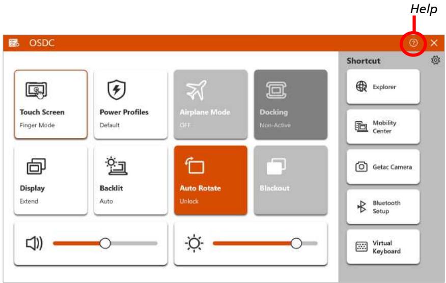
For detailed information on the program, see the program's online help.
G-Manager
G-Manager allows you to view, manage, and configure several system functions and feature. At the left side of the G-Manager screen are the menu items. Select an item to open its menu.
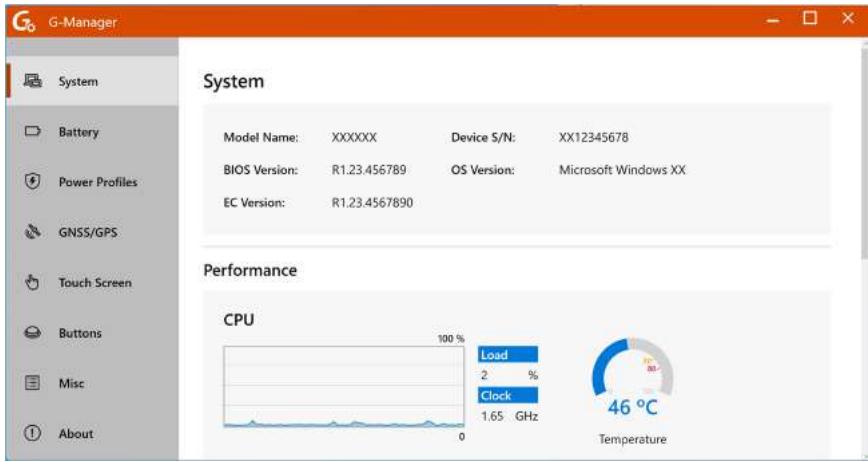
For detailed information, see the program's online help. Select About Help.
NOTE: Not all items are supported by all models. Depending on your model, the actual items and information appearing on the screen can differ from those shown in this manual.
G-Camera
G-Camera is a geo-tagging camera application. Geographical information can be embedded into JPEG files as EXIF 2.2 metadata.
NOTE: G-Camera uses the standard location service of Windows.
To start the G-Camera application, select Start G-Camera.
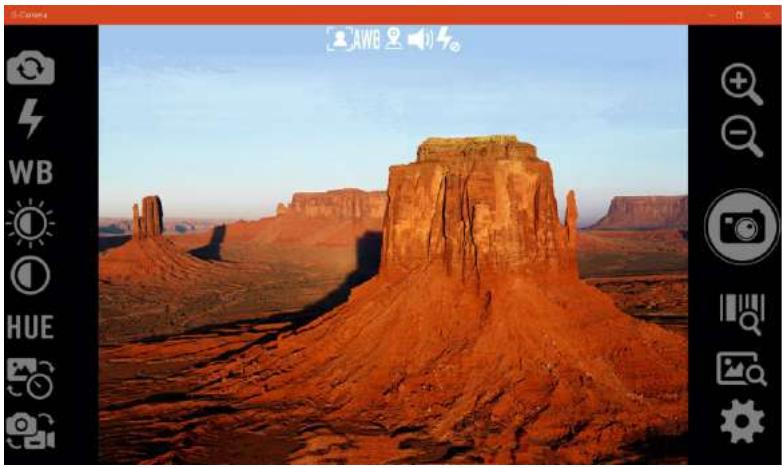
In the middle is the preview window with status display. At the two sides are various buttons.
For detailed information on the program, see the program's online help.
Select Help.
Chapter 7
Care and Maintenance
Taking good care of your computer will ensure a trouble-free operation and reduce the risk of damage to your computer.
This chapter gives you guidelines covering areas such as protecting, storing, cleaning, and traveling.
Protecting the Computer
To safeguard the integrity of your computer data as well as the computer itself, you can protect the computer in several ways as described in this section.
Using an Anti-Virus Strategy
You can install a virus-detecting program to monitor potential viruses that could damage your files.
Using the Cable Lock
You can use a Kensington-type cable lock to protect your computer against theft. The cable lock is available in computer stores.
To use the lock, loop the lock cable around a stationary object such as a table. Insert the lock to the Kensington lock hole and turn the key to secure the lock. Store the key in a safe place.
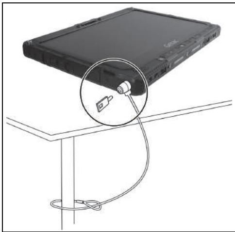
Locking the Tablet
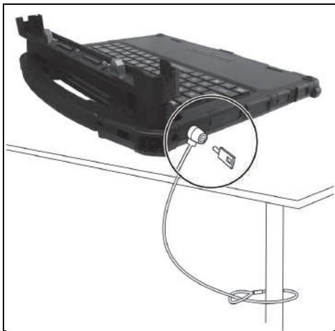
Locking the Keyboard Dock
Taking Care of the Computer
Location Guidelines
- For optimal performance, use the computer where the recommended temperature is between 0^ C (32°F) and 55^ C (131°F). (Actual operating temperature depends on product specifications.)
- Avoid placing the computer in a location subject to high humidity, extreme temperatures, mechanical vibration, direct sunlight, or heavy dust. Using in extreme environments for long periods can result in product deterioration and a shortened product life.
- Operating in an environment with metallic dust is not allowed.
- Place the computer on a flat and steady surface. Do not stand the computer on its side or store it in an upside-down position. A strong impact by dropping or hitting may damage the computer.
- Do not cover or block any ventilation openings on the computer. For example, do not place the computer on a bed, sofa, rug, or other similar surface. Otherwise, overheating may occur that results in damage to the computer.
- As the computer can become very hot during operation, keep it away from objects that are vulnerable to heat.
- Keep the computer at least 13~cm (5 inches) away from electrical appliances that can generate a strong magnetic field such as a TV, refrigerator, motor, or a large audio speaker.
- Avoid moving the computer abruptly from a cold to a warm place. A temperature difference of more than 10^ ( 18^ ) may cause condensation inside the unit, which may damage the storage media.
General Guidelines
- Do not place heavy objects on top of the computer as this may damage the display.
-
To avoid damaging the screen, do not touch it with any sharp object.
-
LCD image sticking occurs when a fixed pattern is displayed on the screen for a prolonged period of time. You can avoid the problem by limiting the amount of static content on the display. It is recommended that you use a screen saver or turn off the display when it is not in use.
- To maximize the life of the backlight in the display, allow the backlight to automatically turn off as a result of power management.
Cleaning Guidelines
- Never clean the computer with its power on.
- Use a soft cloth moistened with water or a non-alkaline detergent to wipe the exterior of the computer.
Gently wipe the display with a soft, lint-free cloth. - Dust or grease on the touchpad can affect its sensitivity. Clean the pad by using adhesive tape to remove the dust and grease on its surface.
- If water or liquid is split onto the computer, wipe it dry and clean when possible. Though your computer is water-proof, do not leave the computer wet when you can dry it.
- If the computer gets wet where the temperature is 0^ C ( 32^ F ) or below, freeze damage may occur. Make sure to dry the wet computer.
Battery Pack Guidelines
- Recharge the battery pack when it is nearly discharged. When recharging, make sure that the battery pack is fully charged. Doing so may avoid harm to the battery pack.
-
The battery pack is a consumable product and the following conditions will shorten its life:
-
when frequently charging the battery pack
-
when using, charging, or storing the battery in high temperature condition
-
To avoid hastening the deterioration of the battery pack thereby prolonging its useful life, minimize the number of times you charge it so as not to frequently increase its internal temperature.
-
Charge the battery pack between 10^ 30^ ( 50^ 86^ ) temperature range. A higher environment temperature will cause the battery pack's temperature to rise. Avoid charging the battery pack inside a closed vehicle and in hot weather condition. Also, charging will not start if the battery pack is not within the allowed temperature range.
- It is recommended that you do not charge the battery pack more than once a day.
- It is recommended that you charge the battery pack with the computer's power off.
- To maintain the battery pack's operating efficiency, store it in a cool dark place removed from the computer and with 30% 40% charge remaining.
- Important guidelines when using the battery pack.
When installing or removing the battery pack take note of the following:
- avoid installing or removing the battery pack when the computer is in Sleep mode. Abruptly removing the battery pack may cause loss of data or the computer may become unstable.
- avoid touching the battery pack terminals or damage may occur, thereby causing improper operation to it or the computer.
The computer's input voltage and surrounding temperature will directly affect the battery pack's charge and discharge time:
- charging time will be prolonged when the computer is turned on. To shorten the charging time, it is recommended that you place the computer in Sleep or hibernation mode.
-
a low temperature will prolong the charging time as well as hasten the discharge time.
-
When using battery power in an extremely low temperature environment, you may experience shortened operating time and incorrect battery level reading. This phenomenon comes from the chemical characteristics of batteries. The appropriate operating temperature for the battery is -10^ C 50^ C ( 14^ F 122^ F ).
- Do not leave the battery pack in storage for more than six months without recharging it.
Touchscreen Guidelines
- Use your finger or the stylus on the display. Using a sharp or metallic object other than your finger or stylus may cause scratches and damage the display, thereby causing errors.
- Use a soft cloth to remove dirt on the display. The touchscreen surface has a special protective coating that prevents dirt from sticking to it. Not using a soft cloth may cause damage to the special protective coating on the touchscreen surface.
- Turn off the computer power when cleaning the display. Cleaning the display with the power on may cause improper operation.
- Do not use excessive force on the display. Avoid placing objects on top of the display as this may cause the glass to break thereby damaging the display.
- In low and high temperatures (below 5^ C / 41^ F and above 60^ C / 140^ F ), the touchscreen may have a slower response time or register the touch in the wrong location. It will go back to normal after returning to room temperature.
- When there is noticeable discrepancy in the operation of the touchscreen function (wrong location on intended operation or improper display resolution), refer to the Windows online Help for instructions on recalibrating the touchscreen display.
When Traveling
- Make sure that the battery pack is fully charged.
- Make sure that the computer is turned off.
- Make sure that all the connector covers are closed completely to ensure the waterproof integrity.
- Do not leave objects in between the keyboard and closed display.
- Disconnect the AC adapter from the computer and take it with you. Use the AC adapter as the power source and as a battery-charger.
- Hand-carry the computer. Do not check it in as luggage.
- If you need to leave the computer in the car, put it in the trunk of the car to avoid exposing the computer to excessive heat.
- When going through airport security, it is recommended that you send the computer and flash disks through the X-ray machine (the device you set your bags on). Avoid the magnetic detector (the device you walk through) or the magnetic wand (the handheld device used by security personnel).
- If you plan to travel abroad with your computer, consult your dealer for the appropriate AC power cord for use in your country of destination.
Chapter 8
Troubleshooting
Computer problems can be caused by hardware, software, or both. When you encounter any problem, it might be a typical problem that can easily be solved.
This chapter tells you what actions to take when solving common computer problems.
Preliminary Checklist
Here are helpful hints to follow before you take further actions when you encounter any problem:
- Try to isolate which part of the computer is causing the problem.
- Make sure that you turn on all peripheral devices before turning on the computer.
- If an external device has a problem, make sure that the cable connections are correct and secure.
- Make sure that the configuration information is properly set in the BIOS Setup program.
- Make sure that all the device drivers are correctly installed.
- Make notes of your observations. Are there any messages on the screen? Do any indicators light? Do you hear any beeps? Detailed descriptions are useful to the service personnel when you need to consult one for assistance.
If any problem persists after you follow the instructions in this chapter, contact an authorized dealer for help.
Solving Common Problems
Battery Problems
The battery does not charge (Battery Charge indicator does not light amber).
- Make sure that the AC adapter is properly connected.
- Make sure that the battery is not too hot or cold. Allow time for the battery pack to return to room temperature.
- If the battery doesn't charge after it has been stored in very low temperatures, try disconnecting and reconnecting the AC adapter to solve the problem.
- Make sure that the battery pack is installed correctly.
- Make sure that the battery terminals are clean.
The operating time of a fully charged battery becomes shorter.
- If you often partially recharge and discharge, the battery might not be charged to its full potential. Initialize the battery to solve the problem.
The battery operating time indicated by the battery meter does not match the actual operating time.
- The actual operating time can be different from the estimated time, depending on how you are using the computer. If the actual operating time is much less than the estimated time, initialize the battery.
Bluetooth Problems
I cannot connect to another device with Bluetooth wireless technology.
- Make sure that both devices have activated Bluetooth feature.
- Make sure that the distance between the two devices is within the limit and that there are no walls or other obstructions between the devices.
-
Make sure that the other device is not in "Hidden" mode.
-
Make sure that both devices are compatible.
Display Problems
Nothing appears on the screen.
- During operation, the screen may automatically turn off as a result of power management. Press any key to see if the screen comes back.
- The brightness level might be too low. Increase the brightness.
- The display output might be set to an external device. Switch the display back to the internal LCD.
The characters on the screen are dim.
- Adjust the brightness and/or contrast.
The display brightness cannot be increased.
- As a protection, the display brightness will be fixed at a low level when the surrounding temperature is too high or too low. It is not a malfunction in this situation.
Bad dots appear on the display at all times.
- A small number of missing, discolored, or bright dots on the screen are an intrinsic characteristic of TFT LCD technology. It is not regarded as an LCD defect.
Clouding (or called "mura") happens on the screen when you exert forces on the left or right side of the LCD frame.
- This is a normal phenomenon, not a defect.
The display has a slower response time in low temperature environments.
- The response time of LCDs can be affected by low temperatures. This does not mean the LCD is defective. The LCD will resume normal response time after returning to room temperature.
Fingerprint Scanner Problems
The following message appears during the fingerprint enrollment process – “Your device is having trouble recognizing you. Make sure your sensor is clean.”
- When enrolling a fingerprint, make sure you move your finger slightly between each reading. Not moving or moving too much can both result in fingerprint reading failures.
The following message appears during the fingerprint login process – “Couldn’t recognize that fingerprint. Make sure you’ve set up your fingerprint in Windows Hello.”
- When placing your finger on the scanner, make sure your finger aims at the center of the scanner surface and covers as much area as possible.
- If a fingerprint login frequently fails, try enrolling again.
Hardware Device Problems
The computer does not recognize a newly installed device.
- The device may not be correctly configured in the BIOS Setup program. Run the BIOS Setup program to identify the new type.
- Make sure if any device driver needs to be installed. (Refer to the documentation that came with the device.)
- Make sure if the device needs any jumper or switch settings. (Refer to the documentation that came with the device.)
- Check the cables or power cords for correct connections.
- For an external device that has its own power switch, make sure that the power is turned on.
Keyboard and Touchpad Problems
The keyboard does not respond.
- Make sure the Keyboard Dock is correctly connected.
Water or liquid is spilt into the keyboard.
- Immediately turn off the computer and unplug the AC adapter. Then turn the keyboard upside down to drain the liquid out of the keyboard. Make sure to clean up any part of the spill you can get to. Though the keyboard of your computer is spill-proof, liquid will remain in the keyboard enclosure if you don't remove it. Wait for the keyboard to air dry before using the computer again.
The touchpad does not work, or the pointer is difficult to control with the touchpad.
- Make sure the Keyboard Dock is correctly connected.
- Make sure that the touchpad is clean.
LAN Problems
I cannot access the network.
- Make sure that the LAN cable is properly connected to the RJ45 connector and the network hub.
- Make sure that the network configuration is appropriate.
- Make sure that the user name or password is correct.
Power Management Problems
The computer does not enter Sleep or Hibernation mode automatically.
- If you have a connection to another computer, the computer does not enter Sleep or Hibernation mode if the connection is actively in use.
- Make sure that the Sleep or Hibernation time-out is enabled.
The computer does not enter Sleep or Hibernation mode immediately.
- If the computer is performing an operation, it normally waits for the operation to finish.
The computer does not resume from Sleep or Hibernation mode.
-
The computer automatically enters Sleep or Hibernation mode when the battery pack is empty. Do any one of the following:
-
Connect the AC adapter to the computer.
- Replace the empty battery pack with a fully charged one.
Wake-on-LAN (WoL) doesn't seem to work.
- If your computer is connected to an older generation of keyboard, office, or vehicle dock, waking up from Microsoft Modern Standby mode is not supported.
Software Problems
An application program does not work correctly.
- Make sure that the software is correctly installed.
- If an error message appears on the screen, consult the software program's documentation for further information.
- If you are sure the operation has stopped, reset the computer.
Sound Problems
No sound is produced.
- Make sure that the volume control is not set too low. Increase the volume.
Make sure that the sound is not muted. - Make sure that the computer is not in Sleep mode.
- If using an external speaker, make sure that the speaker is properly connected.
Distorted sound is produced.
- Make sure that the volume control is not set too high or too low. In most cases, a high setting can cause the audio electronics to distort the sound.
Startup Problems
When you turn on the computer, it does not respond and the Power Indicator does not light green.
- If you are using an external AC power, make sure that the AC adapter is correctly and securely connected. If so, make sure that the electrical outlet works properly.
- If you are using the battery power, make sure that the battery is not discharged.
- When the ambient temperature is below -20^ (-4^) , the computer will start up only if both battery packs are installed.
When you turn on the computer, it stops after POST.
- Reset your computer.
WLAN Problems
I cannot use the WLAN feature.
- Make sure that the WLAN feature is turned on.
Transmission quality is poor.
- Your computer may be in an out-of-range situation. Move your computer closer to the Access Point or another WLAN device it is associated with.
- Check if there is high interference around the environment and solve the problem as described next.
Radio interference exists.
- Move your computer away from the device causing the radio interference such as microwave oven and large metal objects.
- Plug your computer into an outlet on a different branch circuit from that used by the affecting device.
- Consult your dealer or an experienced radio technician for help.
I cannot connect to another WLAN device.
- Make sure that the WLAN feature is turned on.
- Make sure that the SSID setting is the same for every WLAN device in the network.
- Your computer is not recognizing changes. Restart the computer.
- Make sure that the IP address or subnet mask setting is correct.
I cannot communicate with the computer in the network when Infrastructure mode is configured.
- Make sure that the Access Point your computer is associated with is powered on and all the LEDs are working properly.
- If the operating radio channel is in poor quality, change the Access Point and all the wireless station(s) within the BSSID to another radio channel.
- Your computer may be in an out-of-range situation. Move your computer closer to the Access Point it is associated with.
- Make sure that your computer is configured with the same security option (encryption) to the Access Point.
- Use the Web Manager/Telnet of the Access Point to check whether it is connected to the network.
- Reconfigure and reset the Access Point.
I cannot access the network.
- Make sure that the network configuration is appropriate.
- Make sure that the user name or password is correct.
- You have moved out of range of the network.
- Turn off power management.
Other Problems
The date/time is incorrect.
-
Correct the date and time via the operating system or BIOS Setup program.
-
After you have performed everything as described above and still have the incorrect date and time every time you turn on the computer, the RTC (Real-Time Clock) battery is at the end of its life. Call an authorized dealer to replace the RTC battery.
GPS signals drop when they are not supposed to.
- If your computer is connected to the docking station which has one or more USB 3.2/3.1/3.0 devices connected, the USB device can interfere with the radio frequency, causing poor GPS signal reception. To solve the problem in this situation, run the BIOS Setup Utility, go to Advanced Device Configuration Docking USB Port Setting and change the setting to USB 2.0.
Resetting the Computer
You may have to reset (reboot) your computer on some occasions when an error occurs and the program you are using hangs up.
If you are sure the operation has stopped and you cannot use the "restart" function of the operating system, reset the computer.
Reset the computer by any one of these methods:
- Press and hold the P1 button for more than 2 seconds. This opens the Ctrl-Alt-Del screen where you can select actions including Restart.
- If you have the Keyboard Dock: Press Ctrl+Alt+Del on the keyboard. This opens the Ctrl-Alt-Del screen where you can select actions including Restart.
- If the above action does not work, press and hold the power button for more than 5 seconds to force the system to turn off. Then turn on the power again.
System Recovery
Using Windows RE
Windows has a recovery environment (Windows RE) that provides recovery, repair, and troubleshooting tools. The tools are referred to as Advanced Startup Options. You can access these options by selecting Start Settings Update & security Recovery (for Windows 10) or Start Settings System Recovery (for Windows 11).
There are several choices:
- System Restore
This option allows you to restore Windows to an earlier point in time if you have created a restore point.
- Recover from a drive
If you have created a recovery drive on Windows, you can use the recovery drive to reinstall Windows.
- Reset this PC
This option allows you to reinstall Windows with or without keeping your files.
See Microsoft website for more information.
NOTE:
- If you are in a situation where your computer won't boot into Windows, you can access the Advanced Startup Options by running the BIOS Setup Utility and selecting Advanced Windows RE.
- System recovery for Windows typically will take several hours to complete.
Using Recovery Partition
When necessary, you can restore your Windows system to the factory default state by using the "recovery partition" feature. Recovery partition is a portion of your SSD that is set aside by the manufacturer to hold the original image of your system.
WARNING:
- Using this feature will reinstall Windows to your system and configure it to the system's factory default settings. All data on the SSD will be lost.
- Make sure that power is not interrupted during the recovery process. An unsuccessful recovery may result in Windows startup problems.
To restore your system to the factory default state:
- Connect the AC adapter.
- Run BIOS Setup Utility. Select Advanced Recovery Partition. (See Chapter 5 for more information.)
- Follow the onscreen instructions to complete the process.
Using the Driver Disc (Optional)
NOTE: You can download the latest drivers and utilities from Getac website at http://www.getac.com Support.
The Driver disc contains drivers and utilities required for specific hardware in your computer.
Since your computer comes with drivers and utilities pre-installed, you normally do not need to use the Driver disc. In case you want to manually install Windows, you will have to install the drivers and utilities one by one after installing Windows.
To manually install drivers and utilities:
- Start up the computer.
- Prepare an external CD/DVD drive (with USB connection). Connect the drive to your computer. Wait for the computer to recognize the drive.
- Insert the Driver disc. Make sure you use the disc that matches the Windows version of your computer.
- The autorun program should automatically start. You will see the installation menu. Select NEXT to go to the next page if there is more than one.
- To install a driver or utility, just select the particular button and follow the onscreen instructions to complete the installation.
Appendix A
Specifications
NOTE: Specifications are subject to change without any prior notice.
Tablet Specifications
| Parts | Specifications | |
| CPU | Intel Tiger Lake i5 and i7 U series (vPro and non-vPro) | |
| Cache: i5 8MB; i7 12MB | ||
| BIOS | Insyde, Flash EEPROM, 16MB, UEFI, supporting TPM, vPro (optional), NIST, Absolute DDS (optional), WMI, BIOS Diagnostic, Credential guard, Device guard, and MAC passthrough | |
| RAM | 16/32GB DDR4, 3200MHz, SO-DIMM slot x 2 | |
| Video | Controller | Intel® Iris® Xe Graphics Units equipped with dual channel memory come with Intel® Iris® Xe Graphics. |
| Display Panel | 12.5-inch (16:9) TFT LCD with PSR (Panel Self Refresh), FHD 1920 x 1080, dimmer mode, blackout mode, sunlight readable, 1200 nits maximum brightness | |
| Touchscreen | Capacitive, 10-point multi-touch, anti-glare Gorilla Glass | |
| Audio | Features | Azalia, High Definition audio |
| Speaker | 1.5 W x 2 | |
| Microphone | Integrated | |
| Mass storage device | 256GB/512GB/1TB SSD (solid-state drive) in a user-removable canister, PCIe Gen3x4 interface, M.2 2280 type | |
| Card slot | Smart Card (option) | |
| I/O ports | USB 2.0 or RS-232 (option), PowerShare USB 3.2 Gen 1, USB-C Thunderbolt 4, HDMI, combo audio (4-pole TRRS 3.5mm type), RJ45, Docking, tri antenna passthrough | |
| LAN | Intel® i219-LM Gigabit Network Connection, 10/100/1000 Mbps Ethernet | |
| Wireless LAN + Bluetooth | Intel® Wi-Fi 6 AX201 + Bluetooth 5.1 combo | |
| WWAN (option) | Sierra EM7511/EM7565, 3G/4G/4.5G LTE-A | |
| GPS (option) | Internal UART | |
| Camera | Front: FHD 2MP webcam, IR sensor (option) Rear: 8M pixel, autofocus, LED, video capture | |
| Barcode reader (option) | 1D and 2D | |
| RFID reader (option) | Contactless, HF, supporting ISO14443A, ISO14443B, ISO15693, and Sony Felica | |
| Security | Kensington lockTPM 2.0Fingerprint scanner (option) | |
| Power | AC adapter | Universal 90 W; input: 100–240 V AC, 50/60 Hz; output: 19 V |
| Battery pack x 2 | Standard: Lithium-ion Prismatic type, 3-cell | |
| High capacity: Lithium-ion cylindrical type, 4-cell | ||
| Dimension (LxWxD) | 329.5 x 238 x 24 mm (12.9 x 9.3 x 0.9 inches) | |
| Weight | 1.7 kg (3.75 lb) | |
| Environmental | Tempera-ture* | Operating: -31.7 °C to 63 °C (-25 °F to 145 °F)Storage: -51 °C to 71 °C (-60 °F to 160 °F) |
| Humidity | 95% relative humidity, non-condensing | |
| Drop** | 1.8 m (6 ft) drop resistant | |
Table Notes:
- When using the computer with AC power, a low temperature down to -31.7 °C (-25°F) and the temperature range for MIL-STD-810 are supported. When using the computer with only battery power in a temperature down to -21 °C (-6°F) (for standard battery packs) or -29 °C (-20°F) (for high-capacity battery packs), it is advised that the system be booted in a warm environment, if possible, before being taken into an extreme cold environment for work.
** Drop test results vary with different computer configurations and also vary if optional accessories are attached.
Keyboard Dock Specifications
| Parts | Specifications |
| Keyboard | Standard keys with numeric pad keys, 12 function keys, special Fn (Function) key and Windows keys, with water-proof membrane and backlight |
| Pointing device | Glide touchpad, capacitive type |
| I/O ports | USB 3.2 x 3, RS-232, DisplayPort, HDMI, RJ45, docking, tri antenna passthrough |
| Security | Kensington lock |
| Dimension (LxWxD) | 340.5 x 307.5 x 47 mm (13.4 x 12.1 x 1.8 inches) |
| Weight | 1.43 kg (3.15 lb) |
Appendix B
Regulatory Information
This appendix provides regulatory statements and safety notices on your computer.
NOTE: Marking labels located on the exterior of your computer indicate the regulations that your model complies with. Please check the marking labels and refer to the corresponding statements in this appendix. Some notices apply to specific models only.
Safety Notices
About the Battery
If the battery is mishandled, it may cause fire, smoke or an explosion and the battery's functionality will be seriously damaged. The safety instructions listed below must be followed.
Danger
- Do not immerse the battery with liquid such as water, sea water or soda.
- Do not charge/discharge or place the battery in high-temperature (more than 80^ / 176^ ) locations, such as near a fire, heater, in a car in direct sunlight, etc.
- Do not use unauthorized chargers.
- Do not force a reverse-charge or a reverse-connection.
- Do not connect the battery with AC plug (outlet) or car plugs.
- Do not adapt the battery to unspecified applications.
- Do not short circuit the battery.
- Do not drop or subject the battery to impacts.
- Do not penetrate with a nail or strike with a hammer.
- Do not directly solder the battery.
- Do not disassemble the battery.
- Keep the battery away from an extremely low air pressure environment as it may result in an explosion or the leakage of flammable liquid or gas.
Warning
- Keep the battery away from infants.
- Stop using the battery if there are noticeable abnormalities such as abnormal smell, heat, deformities, or discoloration.
-
Stop charging if the charging process cannot be finished.
-
In case of a leaking battery, keep the battery away from flames and do not touch it.
- Pack the battery tightly during transport.
Caution
- Do not use the battery where static electricity (more than 100V ) exists that might damage the protection circuit of the battery.
- When children are using the system, parents or adults must ensure that they are using the system and battery correctly.
- Keep the battery away from flammable materials during charging and discharging.
- In case lead wires or metal objects come out from the battery, you must seal and insulate them completely.
Caution Texts Concerning Lithium Batteries
DANISH
CAUTION: Danger of explosion if battery is incorrectly replaced. Replace only with the same or equivalent type recommended by the equipment manufacturer. Discard used batteries according to manufacturer's instructions.
DEUTSCH
Attention (for USA Users)
The product that you have purchased contains a rechargeable battery. The battery is recyclable. At the end of its useful life, under various state and local laws, it may be illegal to dispose of this battery into the municipal waste stream. Check with your local solid waste officials for details in your area for recycling options or proper disposal.
About the AC Adapter
- Use only the AC adapter supplied with your computer. Use of another type of AC adapter will result in malfunction and/or danger.
- If a ground/earth pin attachment plug on the AC power cord is provided, always plug the cord into a grounded/earthy outlet. Do not disable ground/earth pin of the plug/cord.
- Do not use the adapter in a high moisture environment. Never touch the adapter when your hands or feet are wet.
- Allow adequate ventilation around the adapter when using it to operate the device or charge the battery. Do not cover the AC adapter with paper or other objects that will reduce cooling. Do not use the AC adapter while it is inside a carrying case.
- Connect the adapter to a proper power source. The voltage requirements are found on the product case and/or packaging.
- Do not use the adapter if the cord becomes damaged.
- Do not attempt to service the unit. There are no serviceable parts inside. Replace the unit if it is damaged or exposed to excess moisture.
Heat Related Concerns
Your device may become very warm during normal use. It complies with the user-accessible surface temperature limits defined by the International Standards for Safety. Still, sustained contact with warm surfaces for long periods of time may cause discomfort or injury. To reduce potential heat-related concerns, follow these guidelines:
- Keep your device and its AC adapter in a well-ventilated area when in use or charging. Allow for adequate air circulation under and around the device.
- Use common sense to avoid situations where your skin is in contact with your device or its AC adapter when it's operating or connected to a power source. For example, don't sleep with your device or its AC adapter, or place it under a blanket or pillow, and avoid contact between your body and your device when the AC adapter is connected to a power source. Take special care if you have a physical condition that affects your ability to detect heat against the body.
- If your device is used for long periods, its surface can become very warm. While the temperature may not feel hot to the touch, if you maintain physical contact with the device for a long time, for example if you rest the device on your lap, your skin might suffer a low-heat injury.
- If your device is on your lap and gets uncomfortably warm, remove it from your lap and place it on a stable work surface.
- Never place your device or AC adapter on furniture or any other surface that might be marred by exposure to heat since the base of your device and the surface of the AC adaptor may increase in temperature during normal use.
North America
USA
Federal Communications Commission Radio Frequency Interference Statement
NOTE:
This equipment has been tested and found to comply with the limits for a Class B digital device pursuant to Part 15 of the FCC Rules. These limits are designed to provide reasonable protection against harmful interference in a residential installation. This equipment generates, uses, and can radiate radio frequency energy and, if not installed and used in accordance with the instructions, may cause harmful interference to radio communications.
However, there is no guarantee that interference will not occur in a particular installation. If this equipment does cause harmful interference to radio or television reception, which can be determined by turning the equipment off and on, the user is encouraged to try to correct the interference by one or more of the following measures:
- Reorient or relocate the receiving antenna.
- Increase the separation between the equipment and receiver.
- Connect the equipment into an outlet on a circuit different from that to which the receiver is connected.
- Consult the dealer or an experienced radio/TV technician for help.
Any changes or modifications not expressly approved by the manufacturer could void the user's authority to operate the equipment.
Please note:
The use of a non-shielded interface cable with this equipment is prohibited.
This device complies with Part 15 of the FCC Rules. Operation is subject to the following two conditions:
(1) This device may not cause harmful interference.
(2) This device must accept any interference received, including interference that may cause undesired operation.
| Company name | Getac Inc. |
| Address | 15495 Sand Canyon Rd., Suite 350 Irvine, CA 92618 USA |
| Phone | +1-949-501-9813 |
ANSI Warning
Equipment approved for ANSI/UL121201 and CSA C22.2 No. 213, Nonincidental Electrical Equipment for use in Class I, Division 2, Group A, B, C, and D. Ambient temperature: -29°C to 55°C
EXPLOSION HARZARD WARNING:
- External connections/hubs through the connectors as mentioned (HDMI port, audio port, USB-C port, USB 3.0 port, USB 2.0 port, RJ45 port, DC-in jack, POGO docking port, POGO antenna connector, RS-232 port and VGA port) and super multi DVD/Combo drive are NOT to be used in a hazardous location. When used with a docking station (such as the office dock, keyboard dock, or vehicle dock), the docking/undocking of the equipment must be conducted outside the hazardous area. Docking/undocking in a hazardous area is prohibited.
- The tablet is to be only powered from the battery pack while in hazardous locations. Power adapter is NOT certified to use in hazardous locations and NOT to be used in hazardous locations.
- The battery must only be changed in an area known to be non-hazardous.
- DO NOT disconnect equipment unless power has been switched off or the area is known to be non-hazardous.
- DONOT remove or replace a user-removable item (such as the battery pack, micro-SIM card, smart card, etc.) while the circuit is live unless the area is free of ignitable concentrations.
- Replace the battery with battery model BP3S1P2100S-01 or BP4S1P3450P01, manufactured by Getac Technology Corporation only. Use of another battery may present a risk of fire or explosion.
Radiation Exposure Statement:
The product comply with the FCC portable RF exposure limit set forth for an uncontrolled environment and are safe for intended operation as described in this manual. The further RF exposure reduction can be achieved if the product can be kept as far as possible from the user body or set the device to lower output power if such function is available.
California Proposition 65
For California USA:
Proposition 65, a California law, requires warnings to be provided to California consumers when they might be exposed to chemical(s) identified by Proposition 65 as causing cancer and birth defects or other reproductive harm.
Almost all electronic products contain 1 or more of the chemicals listed under Proposition 65. This does not mean the products pose a significant risk of exposure. As the consumers have the right to know about the products they purchase, we are giving this warning on our packaging and user manual to keep our consumers well informed.

WARNING
This product can expose you to chemicals including lead, TBBPA or formaldehyde, which are known to the State of California to cause cancer and birth defects or other reproductive harm. For more information go to www.P65Warnings.ca.gov
Canada
Canadian ICES-003
CANICES-3(B)/NMB-3(B)
This device contains licence-exempt transmitter(s)/receiver(s) that comply with Innovation, Science and Economic Development Canada's licence-exempt RSS(s). Operation is subject to the following two conditions: (1) This device may not cause interference. (2) This device must accept any interference, including interference that may cause undesired operation of the device.
The device could automatically discontinue transmission in case of absence of information to transmit, or operational failure. Note that this is not intended to prohibit transmission of control or signaling information or the use of repetitive codes where required by the technology.
The device for operation in the band 5150-5250 MHz is only for indoor use to reduce the potential for harmful interference to co-channel mobile satellite systems.
Radiation Exposure Statement
The product complies with the Canada portable RF exposure limit set forth for an uncontrolled environment and are safe for intended operation as described in this manual. The further RF exposure reduction can be achieved if the product can be kept as far as possible from the user body or set the device to lower output power if such function is available.
Where applicable, antenna type(s), antenna models(s), and worst-case tilt angle(s) necessary to remain compliant with the e.i.r.p. elevation mask requirement set forth in section 6.2.2.3 shall be clearly indicated.
5G
User Notification of Take-back Service
To customers in United States and Canada:
Getac believes in providing our customers with easy-to-use solutions to recycle your Getac-brand products for free. Getac understands the customers will likely be recycling multiple items at once and as such. Getac wants to make the recycling process for these larger shipments as streamlined as possible. Getac works with recycling vendors with the highest standards for protecting our environment, ensuring worker safety, and complying with global environmental laws. Our commitment to recycling our old equipment grows out of our work to protect the environment in many ways. For more information, see the Getac Web site at https://www.getac.com/us/environmental-certifications/.
Please see the product type below for information on Getac product, battery and packaging recycling in USA and Canada.
For Product Recycling:
If you have a Getac computer that needs to go to a recycling house, Getac can help you. Just contact us at (866) 394 – 3822 or by email at GUSA.RecycleProgram@getac.com to obtain a prepaid shipping label at no charge to you, pack up your equipment in a box of your choice and send it off.
- For Battery Recycling:
The batteries used to power your portable Getac products contain hazardous materials. While they pose no risk to you during normal use, they should never be disposed with other wastes. Getac provides a free take-back service for recycling your batteries from Getac products. To recycle the battery, please contact us at (866) 394 – 3822 or by email at GUSA.RecycleProgram@getac.com.
For Packaging Recycling:
Getac has chosen the packaging materials used to transport our products carefully, to balance the requirements of shipping the product to you safely while minimizing the amount of material used. Our packaging for notebooks and tablets is recyclable and manufactured using elemental chlorine-free processes. They contain 90 percent (by weight) recycled content. Your packaging materials can be recycled at your local recycling center. Or, if you would like Getac to recycle your packaging, please contact us at (866) 394 – 3822 and we will make arrangements for you.
If you have the above for recycling, please visit our website
https://www.getac.com/us/environmental-certifications/
Europe Marking and Compliance Notices
Statements of Compliance
English
This product follows the provisions of the European Directive 2014/53/EU.
Danish
The device is restricted to indoor use only when operating in the 5150 to 5350 MHz frequency range.
| BE | BG | CZ | DK | DE | EE |
| IE | EL | ES | FR | HR | IT |
| CY | LV | LT | LU | HU | MT |
| NL | AT | PL | PT | RO | SI |
| SK | FI | SE | NO | IS | LI |
| CH | TR | UK (NI) |
Restriction or Requirement in the UK: 5150 to 5350 MHz indoor-use only.


Waste Electrical and Electronic Equipment (WEEE)
This symbol means that according to local laws and regulations your product shall be disposed of separately from household waste. When this product reaches its end of life, take it to a collection point designated by local authorities. Proper recycling of your product will protect human health and the environment.

Battery Directive — Information for Users
In the European Union, this label indicates that the batteries in this product should be collected separately and not be disposed of with household waste. Substances in batteries can have a potential impact on health and environment and you have a role in recycling waste batteries thus contributing to the protection, preservation, and improvement of the quality of the environment.
Restriction of Hazardous Substances (RoHS) Directive
EU RoHS
Getac products meet the requirements of Directive 2011/65/EU on the restriction of the use of certain hazardous substances in electrical and electronic equipment. For more information about RoHS, go to:
https://www.getac.com/us/environment/
CE
| Company name | Getac Technology GmbH. |
| Address | Kanzlerstrasse 4 40472 Dusseldorf, Germany |
| Phone | +49 (0) 211-984819-0 |
UK CA
| Company name | Getac UK Ltd. |
| Address | Getac House, Stafford Park 12, Telford, Shropshire, TF3 3BJ, UK |
| Phone | +44 (0) 1952-207-222 |
About K120-Ex
K120-Ex is suitable for use in potentially explosive atmospheres (zone 2 and zone 22). Follow the instructions in this section if you have the K120-Ex model.
Special Conditions for Safe Use
- Ambient temperature range: -21 °C to +63 °C
- Usage only in controlled environment with suitably reduced pollution.
- The device shall be protected against excessive UV-light.
- The impact test according to IEC 60079-0 was performed with reduced height. The device shall be protected against mechanical impact.
- The connection interfaces shall never be used in hazardous areas.
- The battery shall never be changed, charged or removed in hazardous areas.
- The device shall never be used next to strong charge generating processes.
- Use only rechargeable Li-ion battery of type BP3S1P2100S-01.
Anti-Explosion Protective Covers
All screws and guiding pins on the exterior of K120-Ex are protected by small covers. These covers must remain intact, not to be removed. The dotted circles in the below graphics show where these covers are.
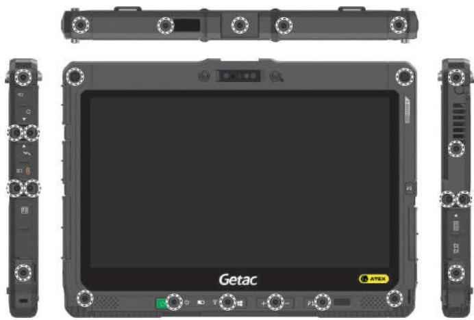
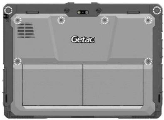
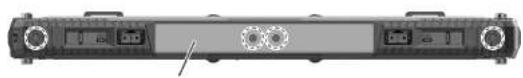
Never remove this I/O cover, which cannot be reinstalled once removed. Therefore, K120-Ex is not to be connected to any docking station.
Use of Accessories
K120-Ex can be used with the following accessories provided by Getac:
Shoulder strap
- Hand strap
Capacitive hard tip stylus and tether
- Digitizer pen and tether (select models only)
ENERGY STAR

ENERGY STAR® is a government program that offers businesses and consumers energy-efficient solutions, making it easy to save money while protecting the environment for future generations.
Please reference ENERGY STAR® related information from http://www.energystar.gov.
As an ENERGY STAR® Partner, Getac Technology Corporation has determined that this product meets the ENERGY STAR® guidelines for energy efficiency.
All Getac products with ENERGY STAR® logo comply with the ENERGY STAR® standard, and the power management feature is enabled by default. Getac's ENERGY STAR® qualified products are listed on the EPA website. https://www.energystar.gov/products
About Battery and External Enclosure Replacement
Battery
The batteries of your product include two battery packs and a button cell (or called RTC battery). All batteries are available from Getac authorized service centers.
The battery pack is user-replaceable. Replacement instructions can be found in "Replacing the Battery Pack" in Chapter 3.
The button cell must be replaced by Getac authorized service centers.
Visit the website at http://us.getac.com/support/support-select.html for authorized service center information.
External Enclosure
The external enclosure of the product can be removed using screwdrivers. The external enclosure can then be reused or refurbished.
The enclosure consists of the DDR cover, four side covers, and the bottom case. See below for information on how to remove the parts.
To remove the DDR cover:
- Remove the battery packs.
- Remove the 9 screws that secure the DDR cover to K120. Detach the cover.
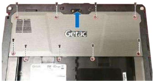
To remove the side covers:
- Remove the DDR cover as described previously.
- Remove the screws as indicated below.
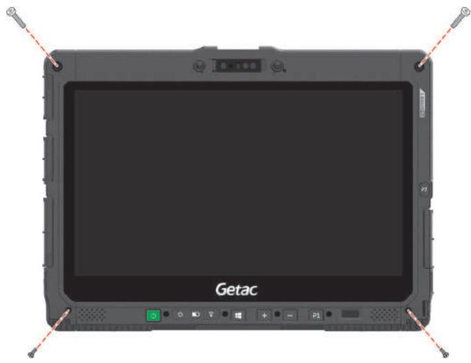
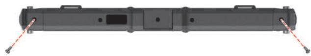
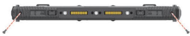
- Remove the screws as indicated below. Detach the left-side cover.
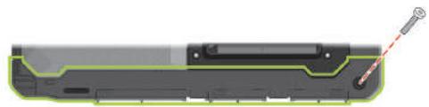
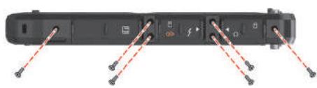
- Remove the screws as indicated below. Detach the right-side cover.
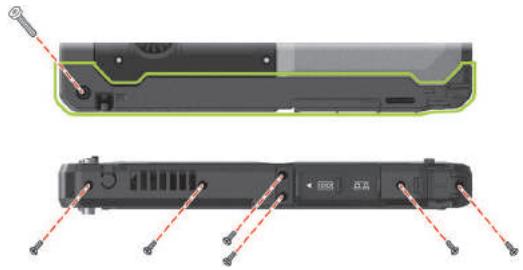
- Remove the screws as indicated below. Detach the upper-side cover.
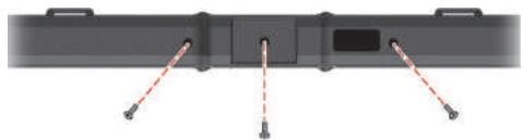
- Remove the screws as indicated below. Detach the lower-side cover.
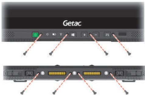
To remove the bottom case:
- Remove the DDR cover and side covers as described previously.
- Remove the screws as indicated below. Detach the bottom case.
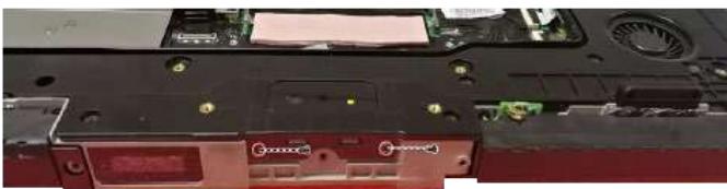
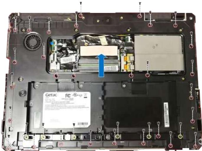
Manufacture Date and Labels
The manufacture date is identified by the second and third digits of the product's serial number.
Example:
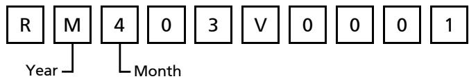
| Code | Year |
| M | 2021 |
| N | 2022 |
| P | 2023 |
| Q | 2024 |
| R | 2025 |
| S | 2026 |
| T | 2027 |
| U | 2028 |
| V | 2029 |
| W | 2030 |
| X | 2031 |
| Y | 2032 |
See the next two pages for the label information.

LASER LIGHT-DO NOT STARE INTO BEAM CLASS 2 LASER PRODUCT RAYONNEMENT LASER NE PAS REGARDER DANS LE FAISCEAU APPAREIL A LASER DE CLASSE 2. MAX. 1 mW: 650 nm. IEC 60825-1.2007 and IEC 60825-1.2014. Pulse duration of 16.8mSec . Complies with 21CFR 1040.10 and 1040.11 except for deviations pursuant to Laser Notice No. 50, dated June 24, 200