
DC Wallbox 25kW - Charger DELTA - Free user manual and instructions
Find the device manual for free DC Wallbox 25kW DELTA in PDF.
User questions about DC Wallbox 25kW DELTA
0 question about this device. Answer the ones you know or ask your own.
Ask a new question about this device
Download the instructions for your Charger in PDF format for free! Find your manual DC Wallbox 25kW - DELTA and take your electronic device back in hand. On this page are published all the documents necessary for the use of your device. DC Wallbox 25kW by DELTA.
USER MANUAL DC Wallbox 25kW DELTA
Installation and Operation Manual
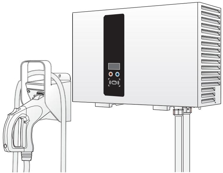
TABLE OF CONTENTS
Introduction 1
Features. 1
Applications 2
Important Safety and Wiring Instructions 3
Installation Site Selection 3
Safety and Compliance 3
Service Wiring 4
Before Installation 7
Safety Requirements 7
Accessory Kit. 8
Recommended Tools 9
Installing the DC Wallbox Charger 10
Making the Connection. 13
Operation 21
System Configuration 23
Cellular Configuration 24
Firmware Update 24
Maintenance 25
System Code 26
Specifications 28
Conventions
General Conventions
The following conventions are used in this manual:

Note:
Indicates additional information that is relevant to the current process or procedure.

WARNING!
Warning information appears before the text it references to emphasize that the content may prevent damage to the device or equipment.

CAUTION!
CAUTIONS APPEAR BEFORE THE TEXT IT REFERENCES. CAUTIONS APPEAR IN CAPITAL LETTERS TO EMPHASIZE THAT THEMESSAGE CONTAINS VITAL HEALTH AND SAFETY INFORMATION.
Typographical Conventions
The following typographical conventions are used in this document:
Italics
Indicates book titles, directory names, file names, path names, and program/process names.
Constant width
Indicates computer output shown on a computer screen, including menus, prompts, responses to input, and error messages.
Constant width bold
Indicates commands or information literally entered by a user on the computer. Variables contained within user input are shown in angle brackets (< >) .
Bold italics.
Indicates keyboard keys that are pressed by the user.
Copyright
The ownership and all intellectual property rights of this Installation and Operation Manual (this "Manual"), including but not limited to the content, data and figures contained herein are vested by Delta Electronics, Inc. ("Delta"). The Manual can only be applied to operation or use of the product. Any disposition, duplication, dissemination, reproduction, modification, translation, extraction or any other usage to the Manual is prohibited without obtaining Delta's prior written permission. As the product will be developed and improved continuously, Delta may modify or update the Manual from time to time without any notice. Delta will do its best efforts to keep the Manual updated and maintain the accuracy of the Manual. Delta disclaims any kinds or forms of warranty, guarantee or undertaking, either expressly or implicitly, including but not limited to the completeness, accuracy, non-infringement, merchantability or fitness for particular purpose or usage.
Copyright © Delta Electronics, Inc. All Rights Reserved.
Introduction
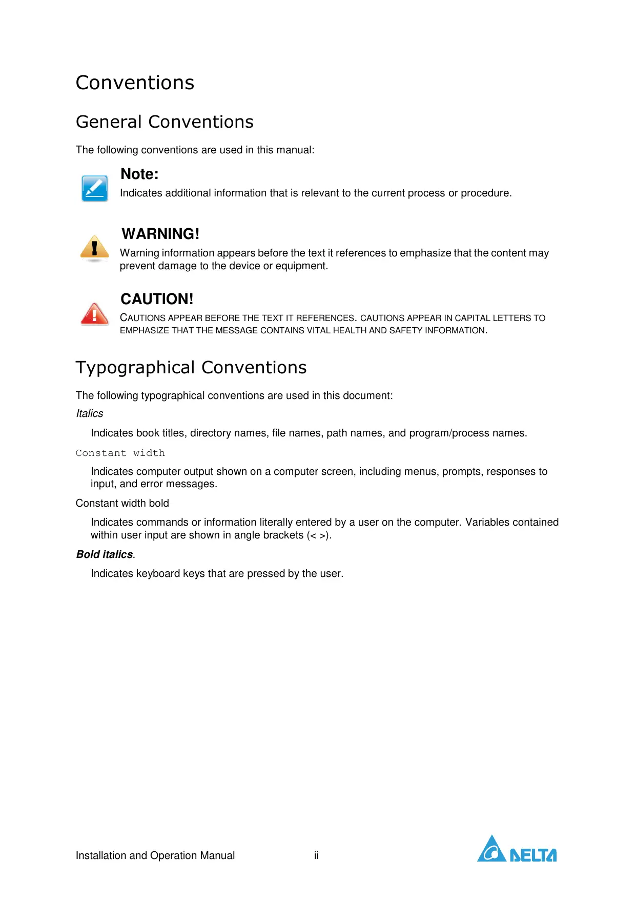
The DC Walbox charger is the top choice for powering battery electric vehicles (BEV and plug-inelectric vehicles (PHEV) today. It is designed for quick charging in both public and private locations, such as retail and commercial parking spaces, fleet charging stations, highway rest areas, workplaces, residences, etc.
The DC Wallbox charger has the advantage of easy installation. The wall-mounting design and pluggable power modules allow for flexible and cost-effective installation at various types of locations. The DC Wallbox charger also features network communication capability; it is able to connect with remote network systems and provide drivers of electric cars real-time information, such as the locations of charging stations, charging progress information and billing information. The DC Wallbox charger has a clear user interface with function buttons, a power supply safety system and excellent waterproof and dust-proof technology to provide the best choice for outdoor environments. It can also integrate with renewable energy systems, such as solar power and wind power technology, to provide the most energy saving infrastructure for EV system development.
Features
- Wall-mount design and pluggable power modules make installation easy and flexible.
- Offers customers the convenience of full start and stop charging control from an authorized RFID smart card.
- Built according to latest industry standards for DC charging.
- Carries an outdoor rating capable of withstanding solid and liquid intrusions in outdoor settings, making the unit more stable and highly reliable.
- Provides a high-contrast, OLED screen interface with multi-function buttons.
Applications
Public and private parking areas
- Community parking areas
- Parking areas of hotels, supermarkets and shopping malls
Workplace parking areas
- Charging stations
Highway rest areas
Important Safety and Wiring Instructions
Installation Site Selection
DC Wallbox can be installed in both indoor and outdoor environments. It is necessary to consider the installation conditions and protection at the site:
- Follow local electrical regulation and installation standards
- Consider the emergency routes at the installation site
- Do not install the device at potentially explosive atmosphere areas (Ex areas).
Safety and Compliance
- Read the manual before installation or usage of device.
- Do not put tools, material or body parts into the electric vehicle connector.
- Do not use the DC Wallbox charger if the cabinet, power cord or charging cable are frayed, have broken insulation or show any other signs of damage.
- Do not install or use the DC Wallbox charger if the enclosure is broken, cracked, open or shows any other indications of damage.
- The DC Wallbox charger should be installed only by a qualified technician.
- Make sure that the materials used and the installation procedures follow local building codes and safety standards.
- The information provided in this manual in no way exempts the user of responsibility to follow all applicable codes or safety standards.
- The manufacturer is not responsible for physical injury, damage to property or damage to equipment caused by the installation of this device.
- This document provides instructions for the DC Wallbox charger and should not be used for any other product. Before installation or use of this product, you should review this manual carefully and consult with a licensed contractor, licensed electrician or trained installation expert to make sure of compliance with local building codes and safety standards.
Service Wiring
Ground Connection
Always connect the Neutral at the service to Earth Ground. If ground is not provided by the electrical service, a grounding stake must be installed nearby. The grounding stake must be connected to the ground bar in the main breaker panel, and the Neutral must be connected to Ground at that point.
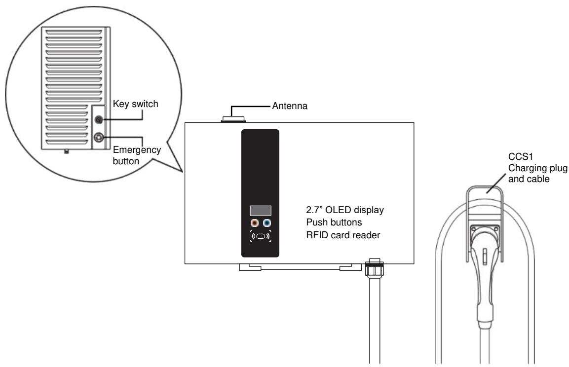
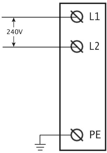
240V Single-Phase

WARNING!
If the DC Wallbox is a single-phase device, do not connect to a three-phase feed.

WARNING!
The following diagram illustrates the DC Wallbox connection to L1 and L2 in a single-phase power grid feed. The earth ground must be connected to neutral at a single point, typically at the breaker panel.

WARNING!
An earth connection is essential before connecting supply.
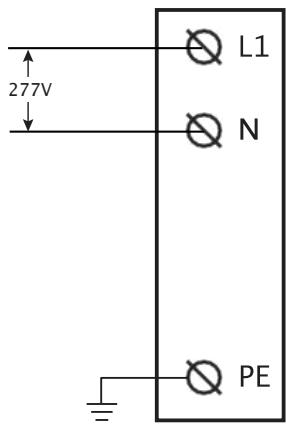
277V Single-Phase

WARNING!
If the DC Wallbox is a single-phase device, do not connect to a three-phase feed.

WARNING!
The following diagram illustrates the DC Wallbox connection to L1 and N in a single-phase power grid feed. The earth ground must be connected to neutral at a single point, typically at the breaker panel.

WARNING!
An earth connection is essential before connecting supply.
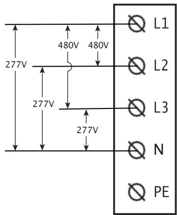
480V Three-Phase

WARNING!
The following diagram illustrates the DC Wallbox connection to L1, L2, L3, and neutral in a y-connection power grid feed. The earth ground must be connected to neutral at a single point, typically at the breaker panel.

WARNING!
An earth connection is essential before connecting supply.
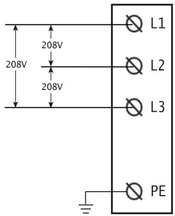
208V Three-Phase

WARNING!
The following diagrams illustrate the DC Wallbox connection to L1, L2, and L3. Neutral connection is not required.

WARNING!
An earth connection is essential before connecting supply.
Before Installation
Safety Requirements
- Be sure to preview the standard operating procedures (SOP) and ensure local building and electrical codes are reviewed before installing the DC Wallbox charger.
- The DC Wallbox charger should be installed by a qualified technician according to the instruction manual and local safety regulations.
- Use appropriate protection when connecting to the main power distribution cable.
- Disconnect switch for each ungrounded conductor of ac input shall be provided by others in accordance with the National Electric Code, ANSI/NFPA 70.

CAUTION!
TO REDUCE RISK OF FIRE FOR 1 PHASE 200VAC-277VAC INPUT, IN ACCORDANCE WITH THE NATIONAL ELECTRIC CODE, ANSI/NFPA 70, THE UPSTREAM CIRCUIT BREAKER SHOULD BE INSTALLED WITH A RATED CURRENT OF 175A.

CAUTION!
TO REDUCE RISK OF FIRE FOR 3 PHASE 480VAC INPUT, IN ACCORDANCE WITH THE NATIONAL ELECTRIC CODE, ANSI/NFPA 70, THE UPSTREAM CIRCUIT BREAKER SHOULD BE INSTALLED WITH A RATED CURRENT OF 50A.

CAUTION!
TO REDUCE RISK OF FIRE FOR 3 PHASE 208VAC INPUT, IN ACCORDANCE WITH THE NATIONAL ELECTRIC CODE, ANSI/NFPA 70, THE UPSTREAM CIRCUIT BREAKER SHOULD BE INSTALLED WITH A RATED CURRENT OF 125A.

Note:
Depends on local regulations requirements.

Note:
This equipment has been tested and found to comply with the limits for a Class A digital device, pursuant to part 15 of the FCC Rules. These limits are designed to provide reasonable protection against harmful interference when the equipment is operated in a commercial environment. The equipment generates, uses, and can radiate radio frequency energy and, if not installed and used in accordance with the instruction manual, may cause harmful interference to radio communications. Operation of this equipment in a residential area is likely to cause harmful interference in which case the user will be required to correct the interference at his own expense.

Note:
To implement cyber security, please follow instruction below:
- EVSE shall connect to the backend system with secure web socket protocol (wss).
Network with cellular (2G/3G/4G) connection shall utilize VPN
Network with WLAN or Ethernet connection shall utilize a router with VPN function - If EVSE support WLAN AP mode for maintenance purpose, please turn off the function after finishing the installation.
CAUTION!
ANY CHANGES OR MODIFICATIONS NOT EXPRESSLY APPROVED BY THE GRANTEE OF THIS DEVICE COULD VOID THE USER'S AUTHORITY TO OPERATE THE EQUIPMENT.
RF Exposure warning:
This equipment must be installed and operated in accordance with provided instructions and the antenna(s) used for this transmitter must be installed to provide a separation distance of at least 20~cm from all persons and must not be co-located or operating in conjunction with any other antenna or transmitter. End-users and installers must be provide with antenna installation instructions and transmitter operating conditions for satisfying RF exposure compliance.
Canada, Industry Canada (IC) Notices
This device contains licence-exempt transmitter(s)/receiver(s) that comply with Innovation, Science and Economic Development Canada's licence-exempt RSS(s). Operation is subject to the following two conditions:
- This device may not cause interference.
- This device must accept any interference, including interference that may cause undesired operation of the device.
Canada, avis d'Industry Canada (IC)
Radio Frequency (RF) Exposure Information
The radiated output power of the Wireless Device is below the Innovation, Science and Economic Development Canada (ISED) radio frequency exposure limits. The Wireless Device should be used in such a manner such that the potential for human contact during normal operation is minimized.
This device has also been evaluated and shown compliant with the IC RF Exposure limits under mobile exposure conditions. (Antennas are greater than 20cm from a person's body).
Contains FCC ID:QIPPLS8-X
Contains IC:7830A-PLS8X
Accessory Kit
Mounting bracket x 1
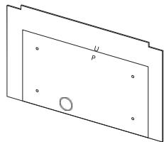
Mounting template x 1
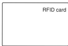
RFID cards x 2

Switch Keys x 2, Latch Keys x 2

User manual x 1
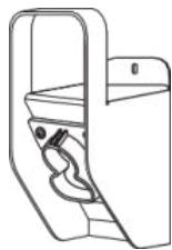
CCS1 plug holder x 1


Bag of bracket screws x2
(SCREW M M618
PAN TORX SUS NL)

Bag of grounding screw x 1
(SCREW M M6112
HEXHCS+PS20CZN-NI)


Bag of expansion bolts x 6
(+2 fordual output model)
(ANCHOR SUS
16*50.8 PICKLING)
Recommended Tools
The following tools are recommended for the DC Walbox charger installation:
(1x) Voltmeter or digital multi-meter
(1x) Water level
(1x) Hammer
(1x) Concrete drilling machine
(1x) Wire cutters / strippers
(1x) Torx® Tamper-Resistant T15 & T25 screwdriver
(1x) No.8 Flathead screwdriver and socket wrench
(1x) No.6 Flathead screwdriver
(1x) No.2 Philips screw driver
(1x) M50 conduit hub, conduit and wrench for main power wires
(1x) M25 conduit hub, conduit and wrench for Ethernet
(2x) Ring terminal RNB70-10 for L/N wire (#2/0 AWG, 90^ copper wire) in models with 240V and 277V single-phase input
(3x) Ring terminal RNB38-6 for L1/L2/L3 wire (#2 AWG, 90^ copper wire) in models with 208V three-phase input
(4x) Ring terminal RNB14-6 for L1/L2/L3/N wire (#6 AWG, 90^ copper wire) in models with 480V three-phase input
(1x) Ring terminal RNB14-6 for PE/ground wire (#6 AWG, 90^ copper wire)
Important Safety Instructions.
Save these Instructions.
- The DC Wallbox charger should be installed only by a licensed contractor, and/or a licensed electrician in accordance with all applicable state, local and national electrical codes and standards.
- Before installing the DC Wallbox charger, review this manual carefully and consult with a licensed contractor, licensed electrician and trained installation expert to ensure compliance with local building practices, climate conditions, safety standards and state and local codes.

WARNING!
Danger of electrical shock or injury. Turn off power at the panel board or load center before working inside the equipment or removing any component. Do not remove circuit protective devices or any other component until the power is turned off.

CAUTION!
TO AVOID DAMAGE TO THE CHARGER OR PERSONAL INJURY, MAKE SURE THE INSTALLATION LOCATION IS ABLE TO SUPPORT THE WEIGHT OF THE DC WALLBOX CHARGER.
Installing the DC Wallbox Charger
Preparation
- Release the screws on the crate (two sides) with a No. 8 socket wrench.
- OOpen top lid of plywood crate.
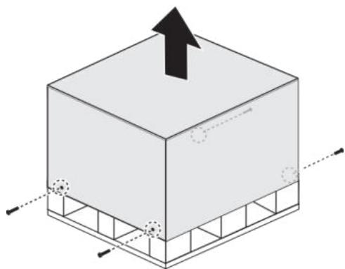
- Take out mounting template and cut off the cable ties to move the charging plug.
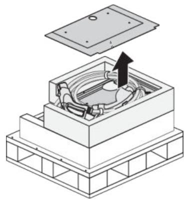
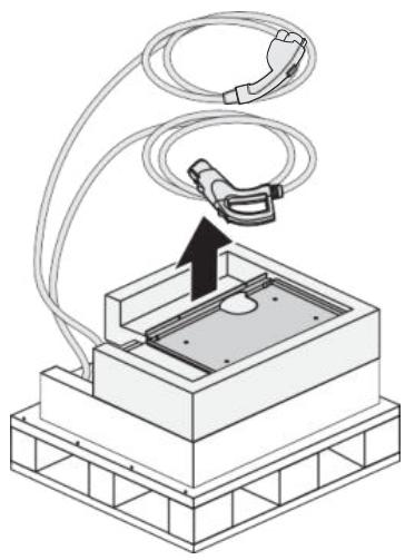
- Remove top foam, open plastic bag and take out the unit.
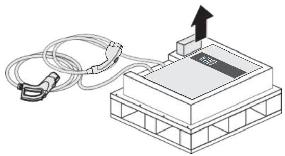

Note: Carefully place the unit and the charging plug on the ground or a flat surface at this stage.
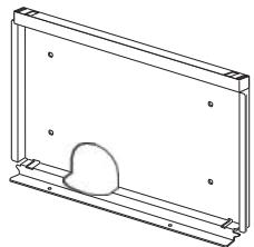
Wall Mounting
- Use template and leveler tool to mark out the mounting position.
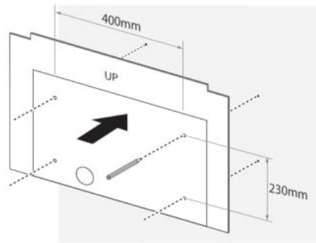
- Mount bracket onto the wall.
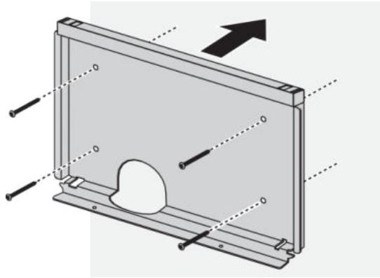

Note:
- The unit must be mounted on a solid wall (concrete or metal preferred).
- Use the expansion bolts in the accessory kit or choose proper mounting screws for different types of wall. A drilling machine might be needed for certain conditions.
- Follow applicable accessibility requirements for the mounting position. The unit must be mounted at a sufficient height from grade such that the height of the storage is located between 60 cm (24 inches) and 120 cm (4 feet) from grade per NEC Article 625.
- Leave a minimum of 650~mm on both sides of the charger for service maintenance.

WARNING!
To ensure adequate ventilation and maintenance space, leave a minimum of 45cm (18 inches) on both sides of the charger.
- Place unit onto bracket. Align the back chassis of unit with the corresponding slot on the bracket. Slowly slide down the unit until it sits firmly on the bracket. Fasten two screws from the bottom.
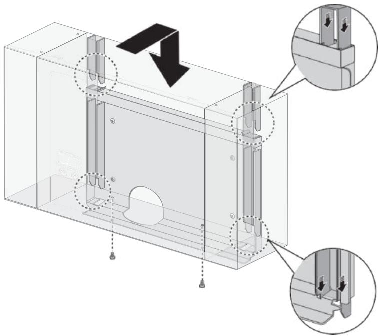

Note:
The bottom fixing screws are in the accessory kit.
Making the Connection

WARNING!
Only use a Torx® Tamper-Resistant T15 screwdriver to secure or remove the screws. Use of any other tool may damage screws and panel.
Power Wiring
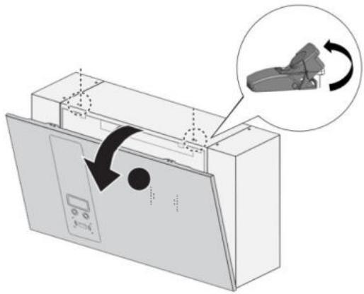
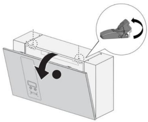
- Open front cover for wiring.
a. Release two screws on top.
b. Release the latches to open front cover.
c. Put down front cover gently.
- Routing the power wires is possible through the bottom or rear of the enclosure.
Select the location to route the power wiring.
Bottom-fed wiring:
a. Feed the wires from the underside. Make sure the wiring can sufficiently reach the connectors before securing.
b. Continue with the fastening of the wires, see the following step.
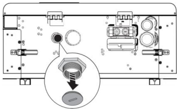
Rear-fed wiring:
a. Remove the waterproof cap from the back of the enclosure and insert the waterproof cap in cable access location on the bottom of the enclosure.
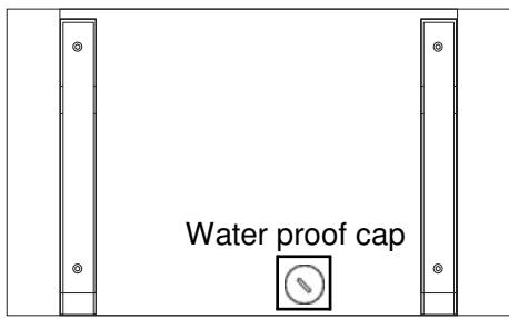
b. Proceed with the following steps.

CAUTION!
BACK-FED WIRING MAY CAUSE THE RISK OF WATER LEAKAGE. DO NOT CHOOSE THIS WIRING CONNECTION IN OUTDOOR LOCATIONS.
- Fasten cable gland to secure wires.
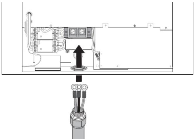

Note:
To insure protection from the elements, make sure to use certified IP55 (or above) cable glands.
- Remove lid of terminal block and connect the wiring to the correct terminals. See the following information for specific model connections.
Wiring requirements are dependent on the model type and between single and three-phase models.

WARNING!
Cable color coding may be defined differently depending on the region.
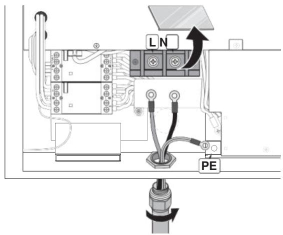
Single-phase
Wiring the 240 / 277V Models
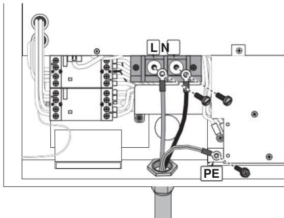
- Conduit hub and conduit size M50 according to EN 61386-24.
- Connect the power wires of 2 × RNB70-10 ring terminal with cable lugs to the input terminal marked with "L" and "N" using 2 × M10.0 screws with 88.4 lb-in Torque force.
- Connect the ground wire of RNB14-6 into the earth terminal marked with ground symbol (12) using 1 × M6.0 screw with 17.7 lb in Torque force.
Three-phase
Wiring the 480V Model
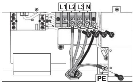
- Conduit hub and conduit size M50 according to EN 61386-24.
- Connect the power wires of 4 × RNB14-6 ring terminal with cable lugs to the input terminal marked with "L1", "L2", "L3" and "N" using 4 × M6.0 screws with 28.7 lb-in Torque force.
- Connect the ground wire of RNB14-6 into the earth terminal marked with ground symbol (12) using 1 × M6.0 screw with 17.7 lb in Torque force.
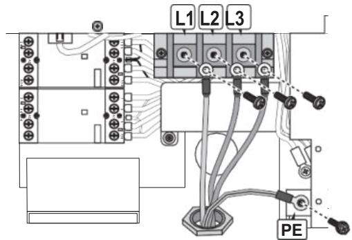
Wiring the 208V Model
-
Conduit hub and conduit size M50 according to EN 61386-24.
-
Connect the power wires of 3 × RNB38-6 ring terminal with cable lugs to the input terminal marked with "L1", "L2" and "L3" using 3 × M6.0 screws with of 28.7 lb-in Torque force.
- Connect the ground wire of RNB14-6 into the earth terminal marked with ground symbol (12) using 1 × M6.0 screw with 17.7 lb in Torque force.
- Neutral wire is not required.

WARNING!
Cable color coding may be defined differently depending on the region.
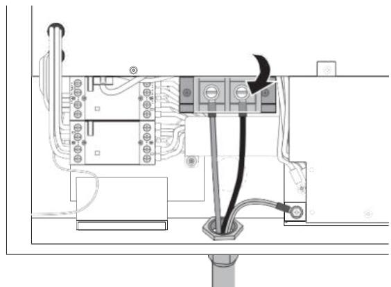
- Fasten each wire with the proper screw. Make sure the correct amount of torque is used. See listed information.
- Place lid back onto terminal block.

CAUTION!
MAKE SURE THE ELECTRIC WIRE CONDUIT IS ALIGNED WITH THE DC WALLBOX CHARGER INPUT WIRE OPENING PRIOR TO INSTALLATION. FAILURE TO DO SO COULD DAMAGE THE WIRING OR THE CHARGER.
- Put front cover back and fasten screws securely.
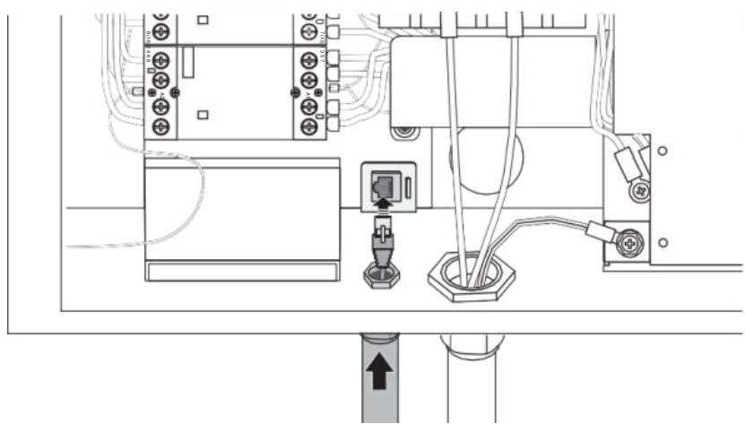
Ethernet Connection
It is recommended to connect Ethernet cables through the underside access ports. It is necessary to open the front cover.
- Remove the water proof cap from the Ethernet access port.
- Insert the cable through the port and connect the Ethernet cable to the terminal.
- Fasten the conduit or cable gland to secure the cable.
Cellular Connection
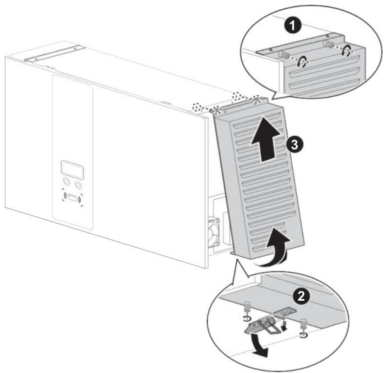
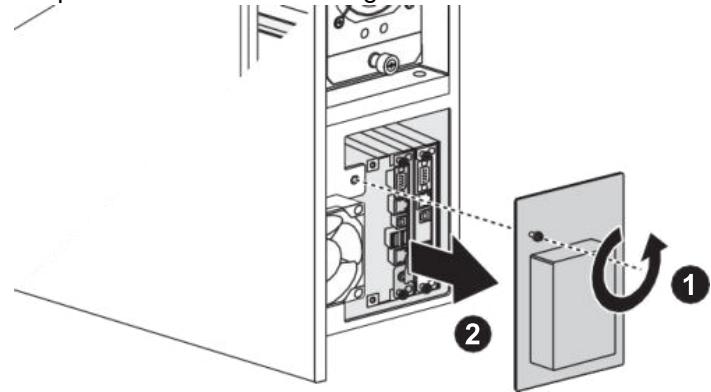
- Remove right filter cover.
a. Release the screws on the top.
b. Release the screws on the bottom and pull out the latch.
c. Open and remove the filter cover.
WARNING!

Only use a Torx® Tamper-Resistant T25 screwdriver to secure or remove the screws of unit. Use of any other tool may damage screws and panel.
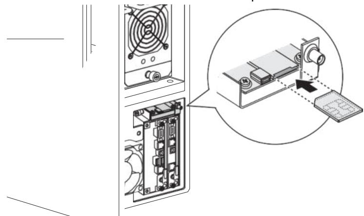
- Remove the protection cover on the right side.
- Insert micro SIM card onto cellular board. Fasten the protection cover back.
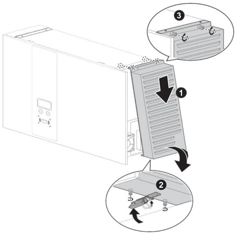
- Return right filter cover.
a. Hang filter cover onto the unit.
b. Pull down the pin and place back filter cover.
c. Fasten screws on bottom.
d. Fasten screws on top.
Set Charging Plug
- Mount charging plug hanger onto the wall.
- Place charging cable and plug on the hanger properly.
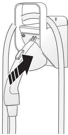
SAE DC (CCS1)
- Switch power on and turn the key to initialize DC Wallbox when all steps are completed
Operation
- Choose the preferred language.
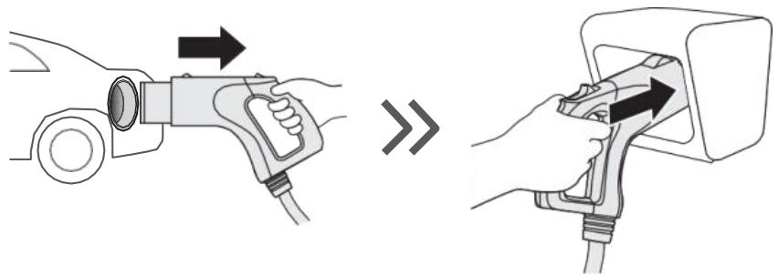
- Connect the plug to the EV.
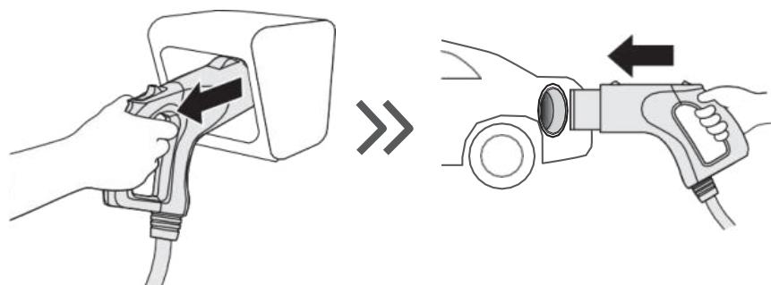
- Swipe the authorized RFID card to start charging.
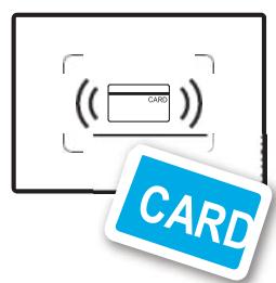
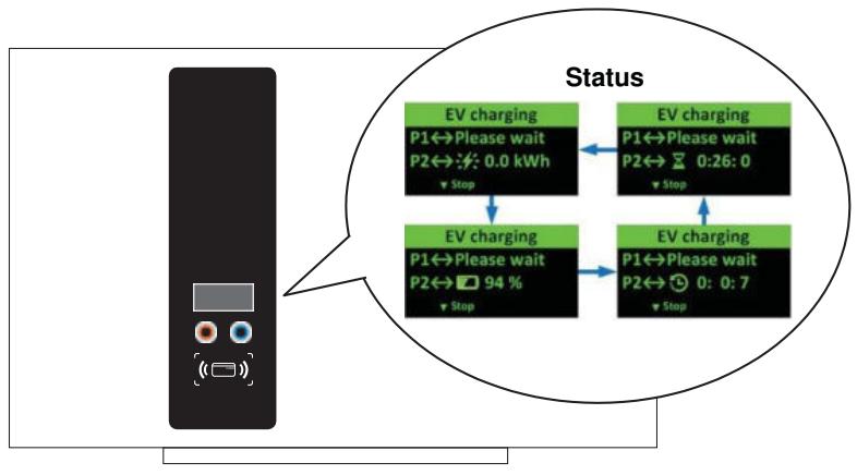
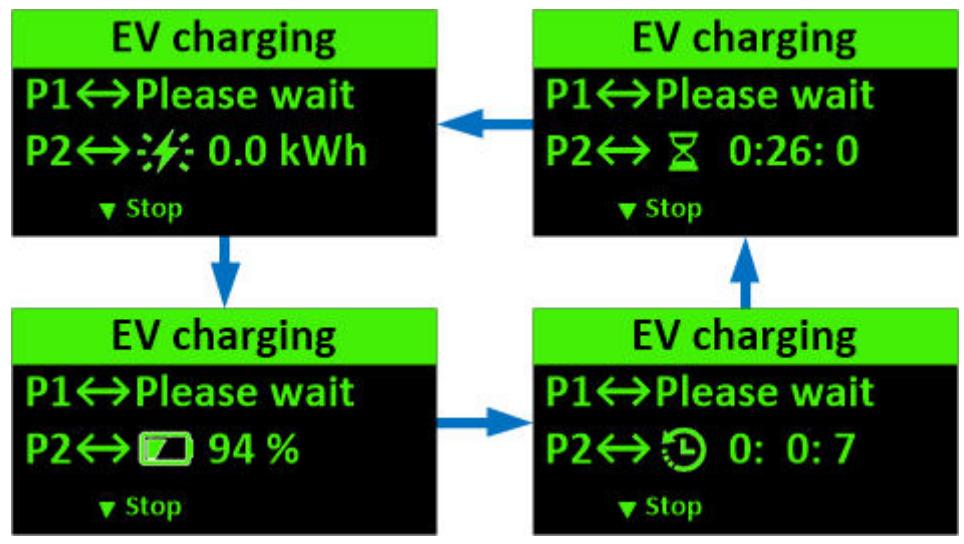
- Once charging commences, status information is displayed on the screen. The following illustrations demonstrate the start to near complete charging procedure.
- Swipe the authorized RFID card to stop.

- Return the plug to the holder.
System Configuration

WARNING!
Only configure the charger when the charger is not in charging mode to avoid interruption of an ongoing charging session.
Steps:
- Contact service provider to login online configuration tool.
- When the configuration is done, copy the parameter file (DeltaDCWallboxConfig) to the root of a USB flash drive (the drive format should be FAT/FAT32, < 32GB).
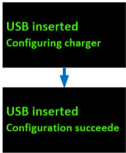
- Insert the USB flash disk into the USB port on the bottom (labeled USB). The configuration will be uploaded to the DC Wallbox.
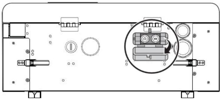
- Remove the USB flash drive when the configuration is complete.
- Close the protection cover. The cover has a hole to put padlock into it to avoid tampering.
Cellular Configuration
For models equipped with the cellular modem, insert a valid cellular (WCDMA) SIM card as detailed in previous steps (page 17) to start cellular connection. Consult with local operator to activate data service on the SIM card beforehand. Disable PIN check on the SIM card before inserting the card into the modem. Request APN information from the operator and make sure APN is configured correctly via the configuration tool.
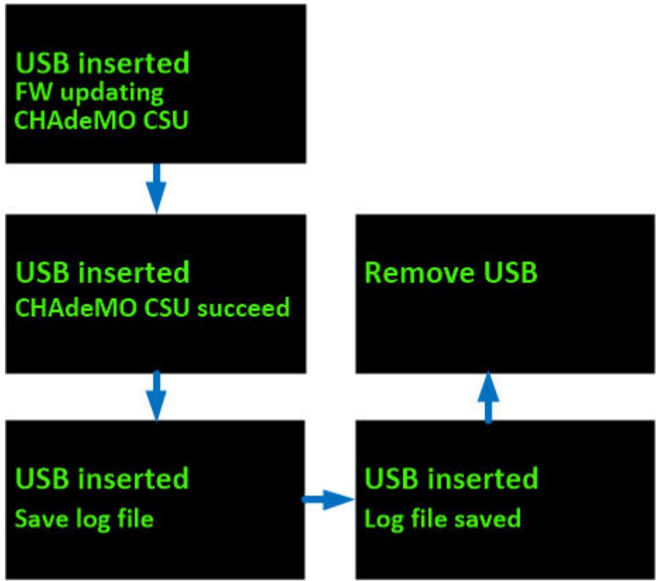
Firmware Update
Firmware updates can be made via the USB port on the bottom of the cabinet.
- Obtain a USB flash drive. The drive format should be FAT/FAT32, < 32GB .
- Insert the USB flash disk into the USB port on the bottom of the unit (labeled USB).
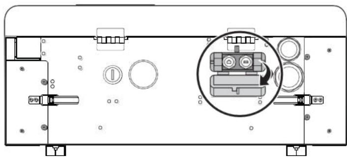
The updated firmware is uploaded to the DC Walbox.
- Close the protection cover. The cover has a hole to put lock into it to avoid tampering. The status is displayed on the panel.
- Close the protection cover. The cover has a hole to put padlock into it to avoid tampering.
Maintenance
Annual Requirements
- Replace the ventilation filter.
- Conduct a visual inspection of the charging cable and ensure that cable does not show any visual damage or deformation.
- Conduct a visual inspection of the charging gun and ensure that gun does not show any visual damage, arcing or rust.

WARNING!
To avoid danger of electrical shock or injury, turn off power at the panel board or load center before working on the equipment or removing any component. Do not remove circuit protective devices or any other component until the power is turned off.
Disconnect electrical power to the DC Wallbox before any maintenance work to ensure that it is separated from the supply of AC mains. Failure to do so may cause physical injury or damage to the electrical system and charging unit.

Note:
- Touching the circuit before the main breaker and auxiliary breaker are switched off may be hazardous. The switching device and other apparatus can only be inspected visually.
- Maintenance of the DC Wallbox shall be conducted only by a qualified technician.
- After opening the front door, turn off the main breaker and auxiliary breaker before any maintenance work.
System Code
| Alarm Code | Description |
| 004001 | System input voltage is higher than workable range (>305 volt) |
| 004002 | System input voltage (L2 or L3) is lower than workable range (<170 volt) |
| 004003 | System output voltage is higher than EV battery maximum voltage |
| 004004 | Request output current from EV is higher than present EVSE ability |
| 004005 | The temperature of air inlet or input contactor is higher than workable range (>60°C) |
| 004006 | The temperature of CCS combo charging plug is higher than workable rangeREMA => (>85°C)Phoenix => (>75°C) |
| 004007 | The air filter need to be replaced |
| 004008 | System fan is attenuated so that need to be replaced |
| 004009 | The self test of system controller is failure |
| 00400A | Emergency button is pressed |
| 00400B | The user authorized by backend is failed |
| 00400C | The user authorized by EVSE itself is failed |
| 00400D | The temperature sensor of air inlet is broken |
| 00400E | The temperature sensor of input contactor is broken |
| 00400F | SPD trigger |
| 004010 | Output fuse at CCS side is broken |
| 004011 | Output fuse at CHAdeMO side is broken |
| 004012 | The temperature sensor of CCS combo charging plug is broken |
| 004013 | the temperature of air inlet or input contactor is lower than workable range (<-40°C) |
| 004014 | User stops charging |
| 004017 | System is timeout if user doesn't plug-in in 3 mnutes after authorized |
| 004018 | Charging time is up (Max: 2hr) |
| 004019 | System data storage is not enough |
| 004020 | Unknown error |
| 004021 | Charging is remotely stopped by backend office |
| 004022 | Input voltage is drop (<20V, <100ms) |
| 004023 | System L1 input voltage is lower than workable range (<170 volt) |
| 005001 | Communication with CHAdeMO EV is broken |
| 005005 | Communication with CCS EV is broken |
| 005006 | Power rectifier is broken (SMR) |
| 005007 | Communication with CCS controller is broken |
| 005008 | Communication with auxiliary power module is broken |
| 005009 | Communication with relay control module is broken |
| 00500C | Communication with display module is broken |
| 00500D | Communication with RFID module is broken |
| 00500E | Cellular module is not ready (module itself or SIM) |
| 00500F | WiFi module is not ready |
| 006001 | Cellular connection is disconnected from APN |
| 006002 | Cellular connection is disconnected from internet |
| 006003 | Cellular connection is disconnected from backend office |
| 006008 | Ethernet connection is disconnected from internet |
| 006009 | Ethernet connection is disconnected from backend office |
| 007001 | Hardware component in power rectifier is broken |
| 007002 | Input voltage of power rectifier is higher than workable range |
| 007003 | Input voltage of power rectifier is lower than workable range |
| 007004 | Output voltage is higher than workable range of power rectifier |
| 007006 | The temperature of air inlet in power rectifier is higher than workable range (>60°C) |
| 007008 | The temperature of PFC is higher than workable range |
| 007009 | The temperature of PFC is lower than workable range |
| 00700A | The temperature of DCDC is higher than workable range |
| 00700B | The temperature of DCDC is lower than workable range |
| 00700C | The fan inside power rectifier is broken |
| 00700D | Output oring diod is broken |
| 00700E | Isolation test is failed |
| 008003 | 5 volt for system controller is higher than workable range |
| 008004 | 5 volt for other system modules is higher than workable range |
| 008005 | 5 volt for CAN bus is higher than workable range |
| 008006 | 12 volt for other system modules is higher than workable range |
| 008007 | 12 volt for EV communication is higher than workable range |
| 008008 | 24 volt for relay control is higher than workable range |
| 008009 | 5 volt for system controller is lower than workable range |
| 00800A | 5 volt for other system modules is lower than workable range |
| 00800B | 5 volt for CAN bus is lower than workable range |
| 00800C | 12 volt for other system modules is lower than workable range |
| 00800D | 12 volt for EV communication is lower than workable range |
| 00800E | 24 volt for relay control is lower than workable range |
| 008010 | The output current of 5 volt for system controller is higher than workable range |
| 008011 | The output current of 5 volt for other system modules is higher than workable range |
| 008012 | The output current of 5 volt for CAN bus is higher than workable range |
| 008013 | The output current of 12 volt for other system modules is higher than workable range |
| 008014 | The output current of 12 volt for EV communication is higher than workable range |
| 008015 | The output current of 24 volt for relay control is higher than workable range |
| 008016 | The temperature of 12 volt for EV communication is higher than workable range |
| 008017 | The temperature of 5 volt for other system modules is higher than workable range |
| 008018 | The temperature of 24 volt for relay control is higher than workable range |
| 008019 | The ambinet temperature of aux. power is higher than workable range |
| 009001 | GFD trigger |
| 009003 | GFD pre-warming |
| 009004 | GFD self-test fail |
| 00A001 | Input contactor 1 is welding |
| 00A002 | Input contactor 1 is driven fault |
| 00A003 | Input contactor 2 is welding |
| 00A004 | Input contactor 2 is driven fault |
| 00A005 | The positive side of output relay for CCS charging is welding |
| 00A006 | The positive side of output relay for CCS charging is driven fault |
| 00A009 | The negative side of output relay for CCS charging is welding |
| 00A00A | The negative side of output relay for CCS charging is driven fault |
| 00B001 | The firmware update of aux. power module is failure |
| 00B002 | The firmware update of relay control module is failure |
| 00B003 | The firmware update of LCM module is failure |
| 00B004 | The firmware update of CCS charging module is failure |
| 00B006 | The firmware update of power converter module is failure |
| 00C001 | PLC module for CCS charging is broken |
| 00C002 | CCS proximity is disconnected |
| 00C003 | stop charging by CCS EV |
| 00D006 | Present output current is different from target current |
| 00D008 | Present output voltage is different from target voltage |
Specifications
| Model | EIDW-U25SXUBXXXXX | EIDW-U25TXUBXXXXX | EIDW-U25LXUBXXXXX |
| Input rating | 200-277 Vac; 60Hz; 134A | 480 Vac; 60Hz; 40A | 208 Vac; 60Hz; 90A |
| Wiring | 1-phase/L1, L2/N, PE | 3-phase/L1, L2, L3, N, PE | 3-phase/L1, L2, L3, PE |
| Power factor | >0.98 | ||
| Current THD | Compliant with IEEE 519 | ||
| Efficiency | 94% at nominal output power | ||
| DC output #1 | SAE J1772 DC Level 2, 100-1000 Vdc, 50A max., 25kW max. | ||
| Protection | Over current, under voltage, over voltage, surge protection, short circuit, over temperature, ground fault | ||
| Display | 2.7" OLED screen | ||
| Push buttons | Multi-functional buttons (LED light: Orange, Blue)/Emergency stop button (Red) | ||
| Authentication | ISO/IEC 14443 Type A/B RFID for user authentication | ||
| Network interface | Ethernet (Standard)Cellular (Standard, Micro SIM card) | ||
| Operating temperature | -22°F to 122°F (-30°C to 50°C) | ||
| Humidity | < 95% relative humidity, non-condensing | ||
| Altitude | Up to 2000 m (6500 ft.) Power derating when altitude > 2000 m | ||
| Ingress rating | Type 3R | ||
| IK rating | IK10 according to IEC62262 | ||
| Cooling | Forced air | ||
| Charging cable | US market-Standard: 7M; Canada: 5M max. | ||
| Dimension (W x H x D) | 680 x 430 x 230 mm (27 x 17 x 9 inches) | ||
| Weight | 45 kg (99 lbs), excluding plug and cable | ||
| Certificate | UL, UL 2202, UL 2231 | ||
DC Wallbox Charger
Contient FCC ID:QIPPLS8-X
Contient IC:7830A-PLS8X