
Système d'osmose - Reverse Osmosis System AEG - Free user manual and instructions
Find the device manual for free Système d'osmose AEG in PDF.
| Product Type | Reverse Osmosis System |
| Brand | AEG |
| Model | Osmosis System |
| Weight | Approximately 8 kg (with tank) |
| Dimensions (unit) | Approximately 30 x 20 x 40 cm |
| Water Supply | Connection to cold water (mains pressure, no electricity) |
| Supply Pressure | 2.7 - 6.8 bar |
| Feed Water pH | 4 - 10 |
| Maximum TDS of Feed Water | 2000 ppm |
| Maximum Hardness | 17 °f (at pH 6.9) |
| Maximum Chlorine | 2.0 ppm |
| Permeate Production (24 h) | 55 liters |
| Water Rejection per Liter Produced | 5 liters |
| TDS Rejection Rate (min.) | 90 - 95% |
| Storage Tank Capacity | 6.4 liters |
| Automatic Shut-off | Yes |
| Number of Filtration Stages | 3: pre-filter (sediment + carbon), RO membrane, post-filter (carbon) |
| Membrane Material | Spiral-wound composite membrane |
| Tank Pressure (empty) | 0.35 - 0.48 bar |
| Cartridge Maintenance | Pre-filter and post-filter: every 6 months; membrane: 1 to 2 years depending on water quality |
| Cleaning and Disinfection | Use of bleach (5.25%) for initial disinfection and after maintenance |
| Spare Parts | Cartridges, membrane, tank, mounting kit, fittings, faucet |
| Repairability | Easy replacement of cartridges and membrane without special tools |
| Warranty | Not specified in the manual |
Frequently Asked Questions - Système d'osmose AEG
User questions about Système d'osmose AEG
0 question about this device. Answer the ones you know or ask your own.
Ask a new question about this device
Download the instructions for your Reverse Osmosis System in PDF format for free! Find your manual Système d'osmose - AEG and take your electronic device back in hand. On this page are published all the documents necessary for the use of your device. Système d'osmose by AEG.
USER MANUAL Système d'osmose AEG
CÓMOCORTARYCONECTARLOS TUBOS
Maintenance. 42 - 43
Diagnostic de pannes 44
Vue éclatée 46
Listedespiecesdetachedes 47
Specifications
Installation and Operation Manual
Reverse Osmosis
How to install, operate and maintain your Reverse Osmosis Drinking Water System
7306601 (Rev J 04/18)
Table of contents
Specifications 49
Unpack and Check Shipment 50
Plan Your Installation 51-52
- Overview and Site Preparation 53
Step A - Install Supply Water Fitting 54
Step B - Install Reverse Osmosis Drain 55-56
Step C - Install Reverse Osmosis Filter Assembly 57
Step D - Install Storage Tank 57
Step E - Install Reverse Osmosis Fucet . 58
Step F - Connect Tubes 59-60
Step G - Sanitize, Pressure Test, Purge System 6162
How Your Reverse Osmosis Water System Works 63
Maintenance 65-66
Troubleshooting 67
Exploded View & Parts List 68-69
Specifications
Supply water temperature limits 5 - 37^
Maximum total dissolved solids (TDS) 2000 ppm
Maximum water hardness @ 6.9 pH . 1.7 mol/m3 (17°f)
Maximum iron, manganese, hydrogen sulfide 0
Chlorine in water supply (max.) 2.0 ppm
Supply water pH limits 4-10 pH
Product (quality) water, 24 hours 1 . 55 liters
Waste water per liter of product water1 5 liters
Percent rejection of TDS, minimum (new membrane)1 .90-95%
Automaticshutoffcontrol. yes
Efficiency2 9.7%
Recovery3 19.7%
1@ Feed water supply at 3.44 bar, 25^ , and 750 TDS --- Quality water production, amount of waste water and percent rejection all vary with changes in pressure, temperature and total dissolved solids.
2Efficiency rating means the percentage of the influent water to the system that is available to the user as reverse osmosis treated water under operating conditions that approximate typical daily usage.
3Recovery rating means the percentage of the influent water to the membrane portion of the system that is available to the user as reverse osmosis treated water when the system is operated without a storage tank or when the storage tank is bypassed.
Non-potable Water Sources: Do not attempt to use this product to make safe drinking water from non-potable water sources. Do not use the system on microbiologically unsafe water, or water of unknown quality without an adequate disinfection before or after the system. This system is certified for cyst reduction and may be used on disinfected water that may contain filterable cysts.
Arsenic Reduction: This system shall only be used for arsenic reduction on chlorinated water supplies containing detectable residual free chlorine at the system inlet. Water systems using an inline chlorinator should provide a one minute chlorine contact time before the reverse osmosis system.
Product Water Testing: The Reverse Osmosis System contains a replaceable treatment component critical for the effective reduction of total dissolved solids. Product water should be tested periodically to verify that the system is performing properly.
Replacement of the reverse osmosis component: This reverse osmosis system contains a replaceable component critical to the efficiency of the system. Replacement of the reverse osmosis component should be with one of identical specifications, as defined by the manufacturer, to assure the same efficiency and contaminant performance.
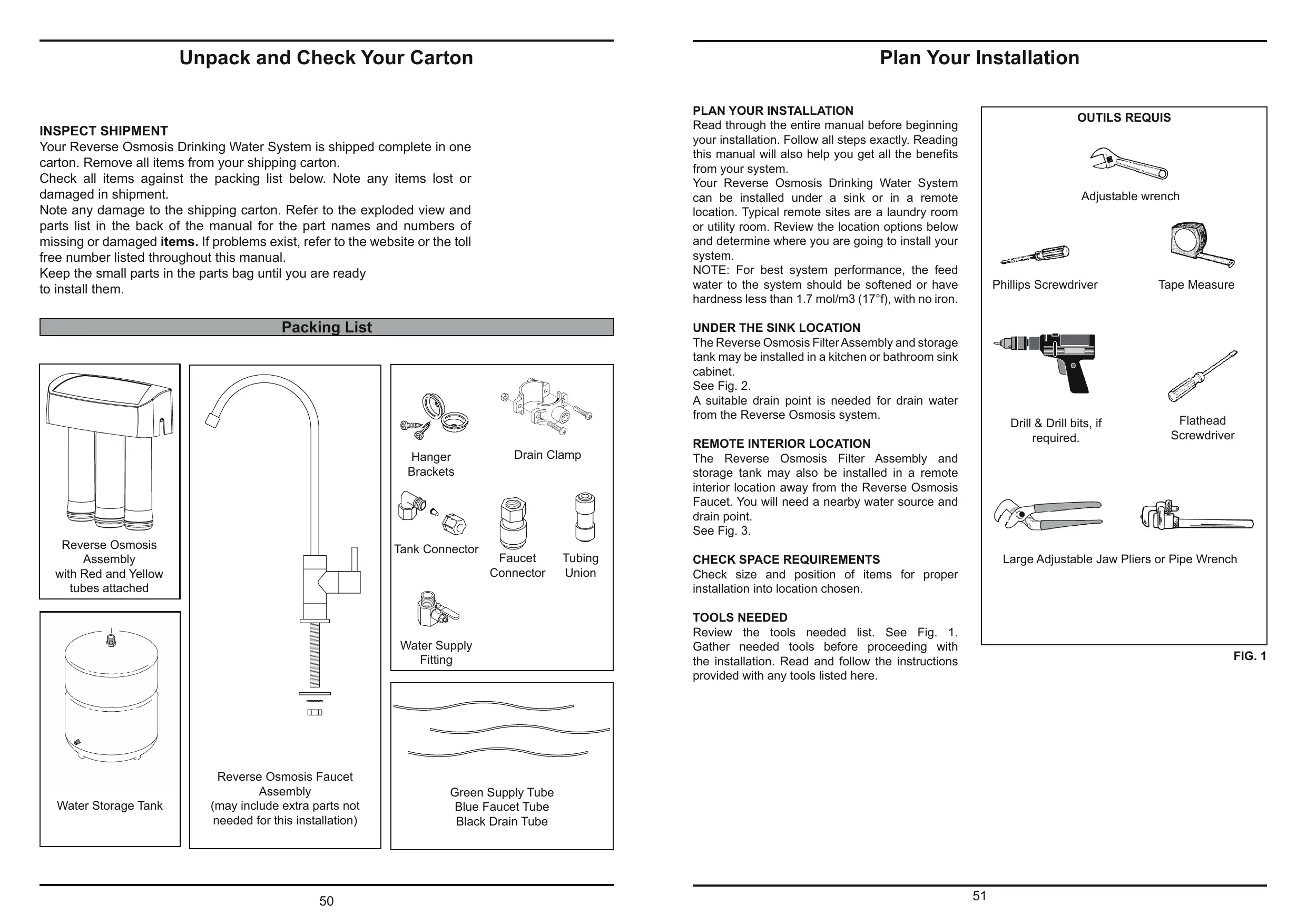
Unpack and Check Your Carton
INSPECT SHIPMENT
Your Reverse Osmosis Drinking Water System is shipped complete in one carton. Remove all items from your shipping carton.
Check all items against the packing list below. Note any items lost or damaged in shipment.
Note any damage to the shipping carton. Refer to the exploded view and parts list in the back of the manual for the part names and numbers of missing or damaged items. If problems exist, refer to the website or the toll free number listed throughout this manual.
Keep the small parts in the parts bag until you are ready to install them.
Packing List
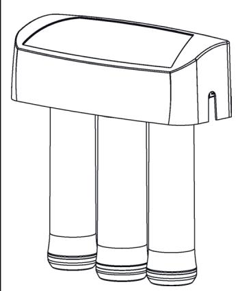
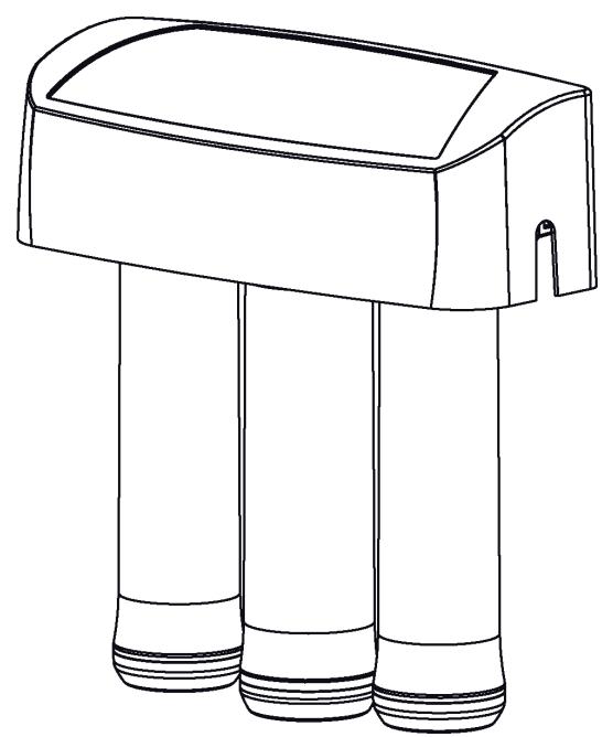
Reverse Osmosis Assembly with Red and Yellow tubes attached

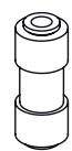
Water Storage Tank
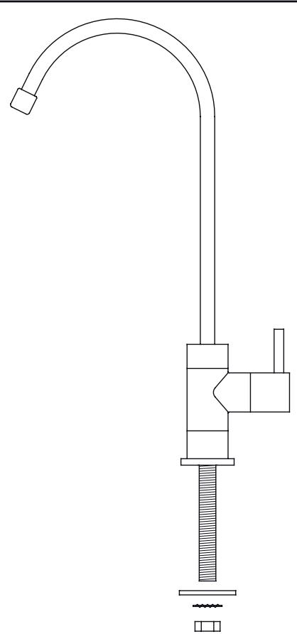
Reverse Osmosis Faucet Assembly (may include extra parts not needed for this installation)
Hanger Brackets
Tank Connector
Drain Clamp
Faucet Connector
Tubing Union
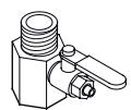
Water Supply Fitting
Green Supply Tube Blue Faucet Tube Black Drain Tube
Plan Your Installation
PLAN YOUR INSTALLATION
Read through the entire manual before beginning your installation. Follow all steps exactly. Reading this manual will also help you get all the benefits from your system.
Your Reverse Osmosis Drinking Water System can be installed under a sink or in a remote location. Typical remote sites are a laundry room or utility room. Review the location options below and determine where you are going to install your system.
NOTE: For best system performance, the feed water to the system should be softened or have hardness less than 1.7 mol/m^3 ( 17^ f ), with no iron.
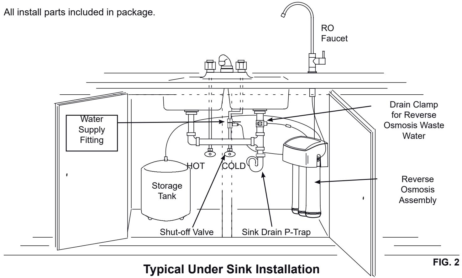
UNDER THE SINK LOCATION
The Reverse Osmosis Filter Assembly and storage tank may be installed in a kitchen or bathroom sink cabinet.
See Fig. 2.
A suitable drain point is needed for drain water from the Reverse Osmosis system.
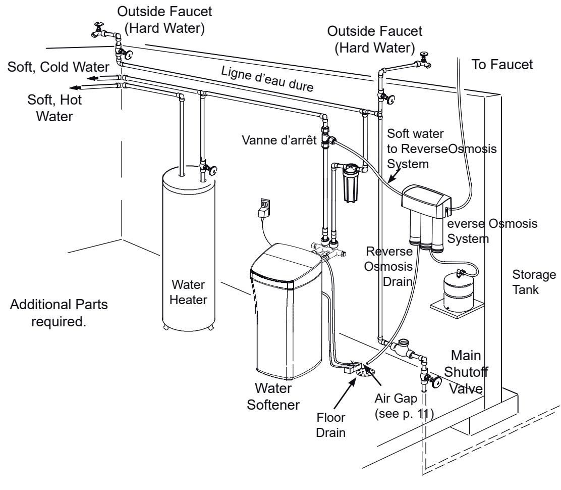
REMOTE INTERIOR LOCATION
The Reverse Osmosis Filter Assembly and storage tank may also be installed in a remote interior location away from the Reverse Osmosis Faucet. You will need a nearby water source and drain point.
See Fig. 3.
CHECK SPACE REQUIREMENTS
Check size and position of items for proper installation into location chosen.
TOOLS NEEDED
Review the tools needed list. See Fig. 1. Gather needed tools before proceeding with the installation. Read and follow the instructions provided with any tools listed here.
OUTILS REQUIS
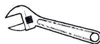
Adjustable wrench
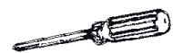
Phillips Screwdriver
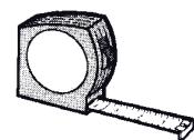
Tape Measure
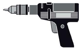
Drill & Drill bits, if required.
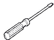
Flathead Screwdriver

Large Adjustable Jaw Pliers or Pipe Wrench
FIG. 1
Plan Your Installation
Typical Remote Installation
Overview and Site Preparation
OVERVIEW
Read through the entire manual before beginning your installation.
There are seven steps to installing your Drinking Water system. They are as follows:
STEP A - Install Cold Water Supply fitting
STEP B - Install Drain Adapter
STEP C - Install Reverse Osmosis Assembly
STEP D - Install Storage Tank
STEP E - Install Reverse Osmosis Facet
STEP F - Connect Tubing
STEP G - Sanitize, Pressure Test, Purge System
These steps are explained in detail over the next few pages. Follow all steps. Reading this manual will also help you receive and use all the benefits your Reverse Osmosis system can give you.

FIG. 4
PREPARE SITE FOR INSTALLATION
- Before starting, close the hot and cold water shutoff valves (See Figure 5).
- Temporarily place tank and filter assembly into planned location. Check position of items and space required for proper installation. Ensure tubes may be routed without kinking.
- Remove tank and filter from planned location and set aside.
NOTE: You must check and comply with all local plumbing codes.
NOTE: For best system performance, the feed water to the system should be softened or have hardness less than 1.7 mol/m3 (17°f), with no iron.
Step A - Install Supply Water Fitting
Check and comply with national and local plumbing codes as you plan, then install a supply (cold) water fitting. The fitting must provide a leak tight connection to the RO 1/4» (6.35 mm) OD tubing, see Figure 20, page 13. A typical installation, using standard plumbing fittings is shown in Figure 5.
IMPORTANT: Before starting, close the hot and cold water shutoff valves (See Figure 5). Use a pan to catch water when disassembling the pipe.
Complying with plumbing codes, install a fitting on the cold water pipe to adapt 1/4 (6.35 mm) OD tubing. A typical connection is shown in Figure 5. You can use solder or threaded fittings. If threaded fittings are used, be sure to use pipe joint compound or Teflon tape on outside threads.
Do not connect the tubing to the fitting at this time.
This will occur later in the installation (page 13).
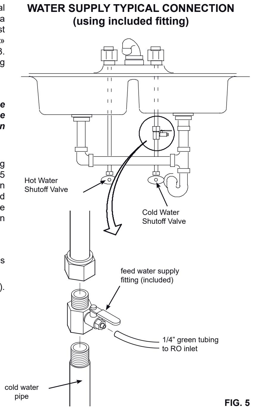
FIG. 5
Step B - Install RO Drain Under Sink
INTRODUCTION
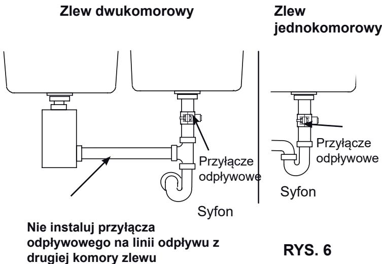
A suitable drain point is needed for the drain water from the Reverse Osmosis filter. You have two options:
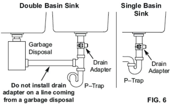
- Install the Drain Adapter included with your unit
As shown in Figures 6 and 7, the drain adapter is installed onto your sink's drain pipe above the P-trap. This is normally used for under sink installations.
- Use another existing drain in your home
As shown in Figures 8 and 9, the drain tube from the RO filter runs directly to an open drain. This is often used for remote location installations.
NOTE: Local code may restrict the type of drain installation to use. Either drain installation type, if permitted by code, may be used in under sink or remote location installations. Consult a plumber if you are not familiar with plumbing procedures.
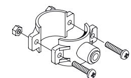
INSTALL DRAIN ADAPTER
(Under sink Installation)
The drain adapter included with your RO system is designed to fit around a 1 - 1 / 2" (3.8 cm) O.D. drain pipe. In the following procedure, you will install the drain adapter above (upstream of) the P-trap. See Fig. 6. Be sure to comply with local plumbing codes.
NOTE: Before starting this procedure, inspect the drain pipe under the sink for corrosion, and replace if necessary, before continuing with installation.
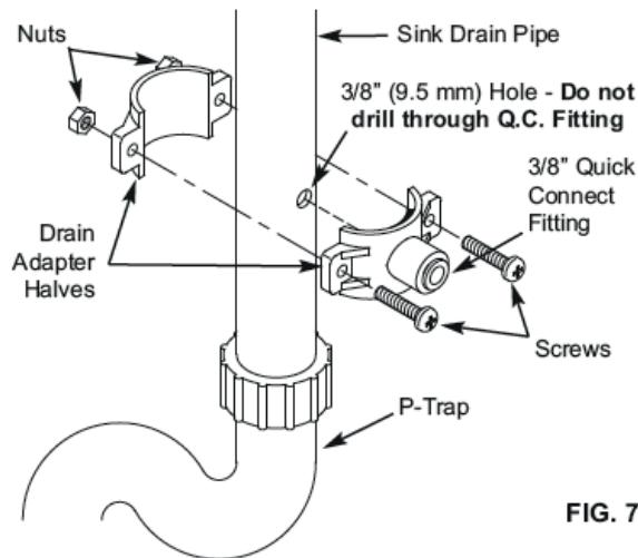
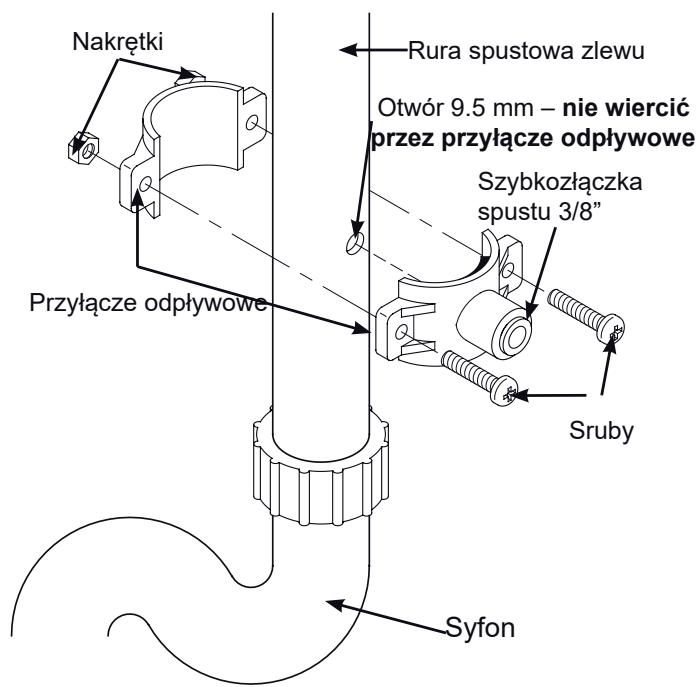
- Test fit the two halves of the drain adapter onto the sink drain pipe, about 6 inches (15 cm) above the Ptrap (See Fig. 7). Make sure that the Q.C. fitting is toward the direction of the RO filter.
NOTE: Locate so that the drain tubing from the Reverse Osmosis filter will run straight to the adapter, with no dips, loops, or kinks.
- Using the hole through the drain fitting as a guide, mark the pipe where a 3/8 (9.5 mm) hole will be drilled (See Fig. 7), and remove the drain adapter from the pipe.
NOTE: Do not drill through the drain adapter's Q.C. fitting, as this could damage the o-ring.
-
Drill a 3/8 (9.5 mm) dia. hole in the pipe and remove flash.
-
Clean the sink tailpiece to assure a leak-tight fit.
-
Place the halves of the drain fitting back onto the sink drain pipe. Use a pencil or similar pointed object to align the Q.C. fitting so that it is centered on the hole you drilled.
-
Assemble the nuts and screws, as shown in Figure 7, and tighten both sides equally to secure the drain adapter halves onto the pipe. Do not overtighten.
Under the Sink Installation
Step B - Install RO Drain In Remote Location
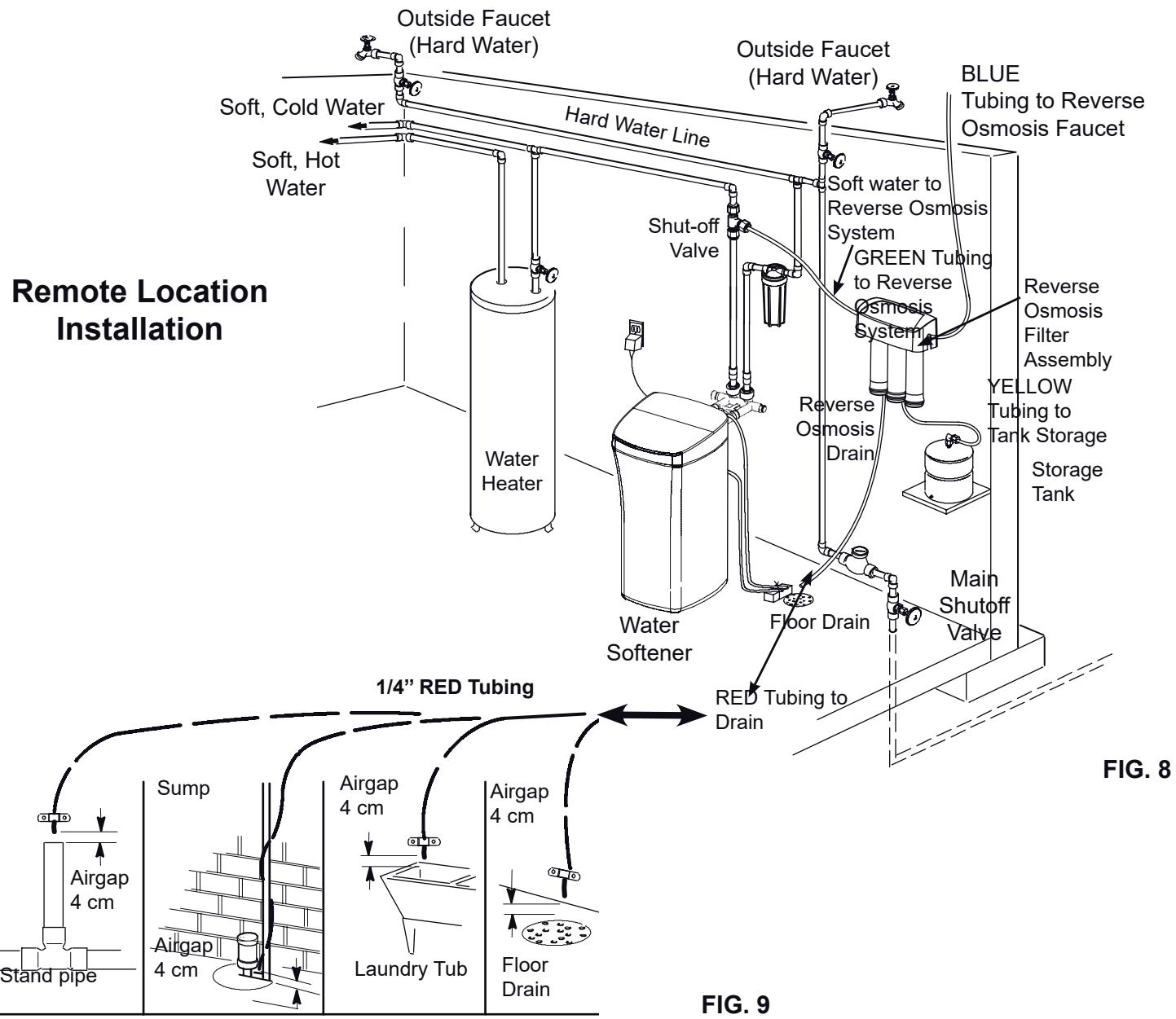
FIG. 9
INSTALL A REMOTE DRAIN POINT AND AIR GAP (Remote Location)
Route the drain tubing to an existing drain in the house. A floor drain, laundry tub, standpipe, sump, etc. are suitable drain points. See Fig. 9. This type of drain is the preferred over the p-trap drain adapter.
Always be sure to provide a 4 cm air gap between the end of the hose and the drain point. This will prevent water from backing up into the system.
NOTE: Check your local plumbing codes.
To install a remote drain point, complete the following steps:
- Locate the 14 " (6.35 mm) red tubing on the Reverse Osmosis filter assembly. See Fig. 8.
- Determine if this length is long enough to reach the drain point. Longer lengths of tubing (see parts list in back of manual) may be needed.
- If longer tubing is required, disconnect the 1/4" (6.35 mm) red tubing and replace with an adequate length of tubing to reach the drain point. Refer to Step F later in the manual on how to disconnect and connect tubing.
NOTE: A flow control insert is located inside the elbow fitting that the drain tube connects to. Refer to Fig 25. Leave this fitting in place.
- Route the tubing to the drain point and secure at the end with a bracket (not included). See Fig. 9. Provide a 4cm air gap between the end of the tube and the drain. See Fig. 9.
Step C: Install RO Filter Assembly
INSTALL REVERSE OSMOSIS FILTER ASSEMBLY
The Reverse Osmosis Filter Assembly is mounted on hanger washers.
See Fig 10. The hanger washers allow you to lift the filter assembly from the washers without any hardware removal. When planning your installation, you need to leave room for changing filters.
Complete the following steps to install your Reverse Osmosis Filter Assembly:
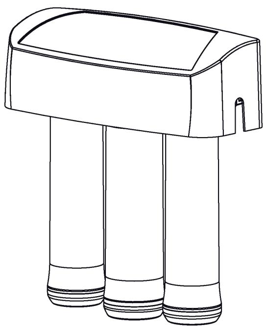
- Remove the cover.
- Locate mounting slots on back inside of the assembly. See Fig 10.
- Hold the assembly up to the wall surface and mark locations for the hanger washers. See Fig 10. Mount the unit high enough to allow room to change filters without taking the unit off of the wall.
- Fasten the hanger washers to the wall using the wood screws provided.
- Hang assembly on washers.
- Replace cover.
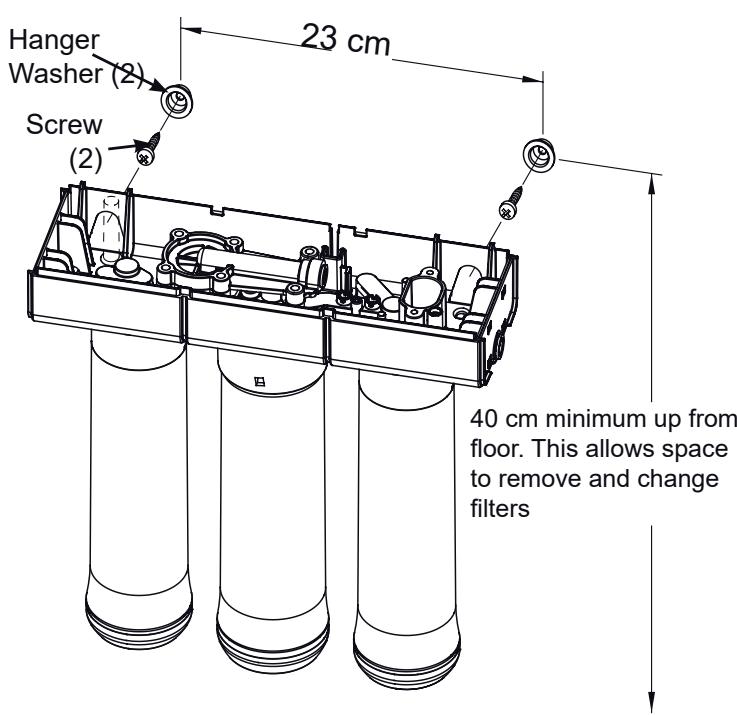
FIG. 10
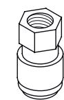
Step D - Install Storage Tank
The fitting on the supply tank may need to be tightened 7-8 full turns to get a good seal.
Do not overtighten.
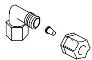
INSTALL STORAGE TANK
- Apply of thread sealing tape (2 wraps clockwise) to the threads on the nipple at the top of the tank. See Fig 11.
- Locate the tubing connector. See Fig. 11. Tighten the tubing connector onto the tank nipple 7-8 full turns, being careful not to cross thread or overtighten.
- Do not connect the tube at this time. This will occur later in the assembly.
- Place the storage tank next to the Reverse Osmosis Assembly. The tank can be placed upright or on its side.
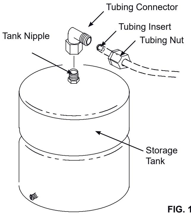
FIG. 11
Step E: Install RO Facet
FAUCET MOUNTING HOLE
You will need to select the location of the Reverse Osmosis
Faucet. You have three options to choose from:
- Use an existing sink top hole (Must be 1.27 cm in diameter)
- Drill a new hole in the sink
-
Drill a new hole in the countertop next to the sink
-
Determine where you are going to install your Reverse Osmosis Faucet.
- Check to ensure the Reverse Osmosis faucet will mount flat against the mounting surface.
- Visually review the routing of the tubes from the Reverse Osmosis filter assembly to the faucet. Check to ensure there is adequate tube routing space between the faucet and filter assembly.
- If drilling is needed, drill a 1.27 cm diameter hole in the mounting surface.
IMPORTANT: Drilling holes into countertops and sinks should only be performed by an installer who is qualified for drilling such materials. Drilling of surfaces made of stone or solid surface materials such as granite, marble, Corian™ or other plastic resin products or sinks made of porcelain or stainless steel may cause permanent, irreparable damage to the sink or countertop surface.
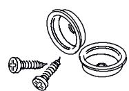
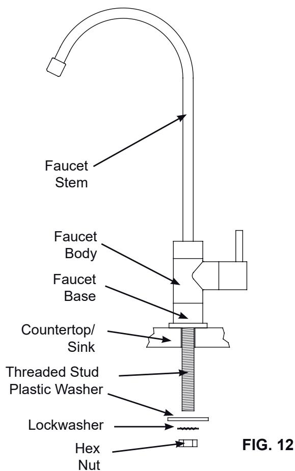
INSTALL REVERSE OSMOSIS FAUCET
- Locate and organize your RO faucet install parts. Refer to Fig. 12.
NOTE: There may be extra parts in the faucet kit not used for this installation. - Assemble the faucet body, base and stem, as shown in Figure 12.
- Feed the threaded stud down through the sink hole until the faucet base is flat against the sink surface.
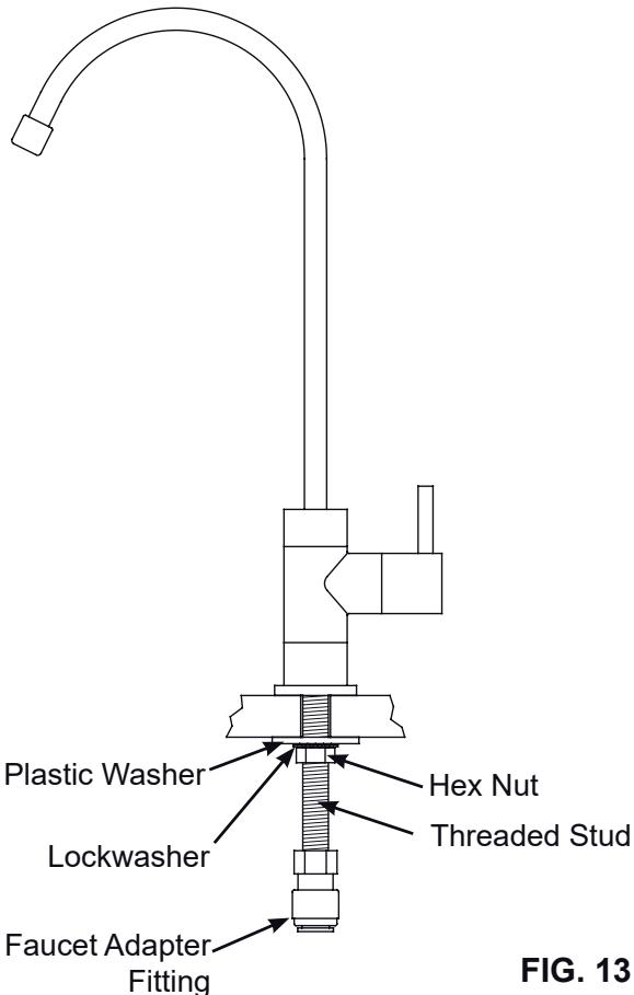
- Install the plastic washer, lockwasher and hex nut onto the threaded stud, in the order shown in Figures 12 & 13. Do not overtighten hex nut.
- Locate the faucet adapter fitting, and thread it onto the stud base, as shown in Figure 13. Do not overtighten.
Step F - Connect Tubes
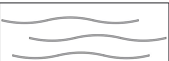
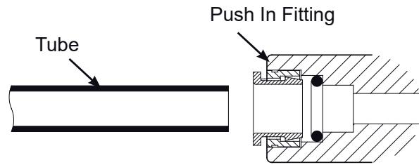
HOW TO CUT AND CONNECT THE TUBES
Your Reverse Osmosis system includes push-in fittings for quick tubing connection. Review the following instructions before connecting the tubes in the next step. Failure to follow these instructions may lead to future leaks.
Cut tubes to length
- Use a sharp cutter or knife to cut the end of tubing.
- Always cut the tubing square. See Fig. 15.
- Inspect the tube up to 2.5cm from the end to be sure there are no nicks, scratches or other rough spots. If needed, cut the tubing again. See Fig. 15.
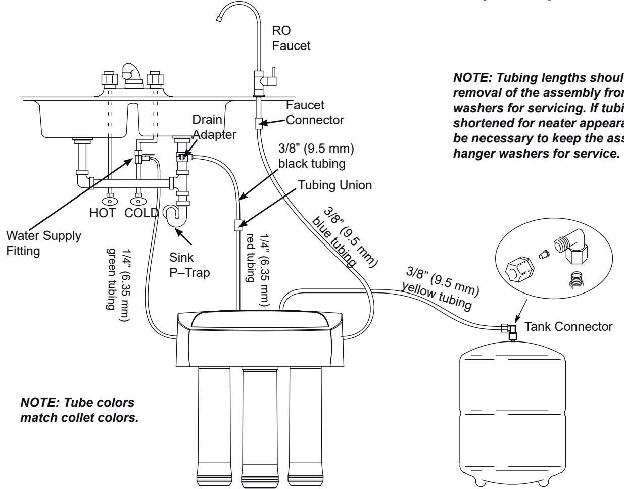
NOTE: Tubing lengths should allow for the removal of the assembly from the hanger washers for servicing. If tubing lengths are shortened for neater appearance, it may be necessary to keep the assembly on the hanger washers for service.
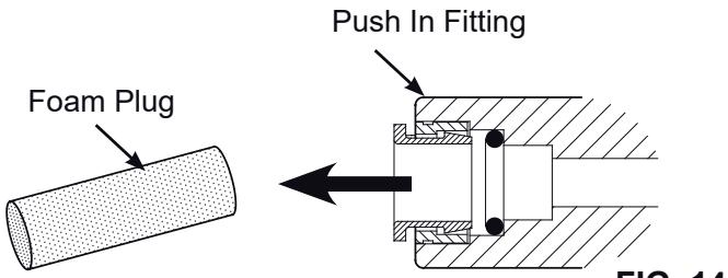
Connect tubes
NOTE: Remove protective foam plugs before connecting tubes (See Fig. 14). Discard foam plugs.
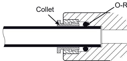
- Push tubing through collet, until it engages the o-ring. See Fig. 16. Continue pushing until the tube bottoms out against the back of the fitting. See Fig. 17. Do not stop pushing when the tube engages the o-ring. Failure to follow these instructions may lead to future leaks. When a 1/4'' (6.35 mm) tube is fully engaged, 1.7 ~cm of the tube has entered the fitting. When a 3/8'' (9.5 mm) tube is fully engaged, 1.9 ~cm of the tube has entered the fitting. Mark tube with a piece of tape or marker. See Figs. 16 & 17.
- If additional tubing is required, see parts list at the end of this manual.
To Disconnect Tubes
- Push the collet inward with a finger tip. See Fig. 19.
- Continue holding collet inward while pulling the tubing out. See Fig. 19.
Remove and Discard Foam Plugs
Cut tubing square with end of tubing round, smooth, with no cuts, nicks or flat spots.
Tube Correctly Cut
FIG. 15
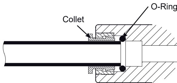
FIG. 16
Tube Partially Engaged With Fitting
FIG. 17
Tube Fully Engaged With Fitting
O-Ring
Collet and O-ring
Collet
Fitting
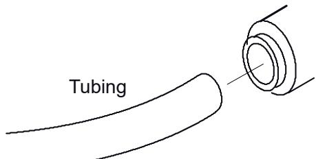
FIG. 18
Collet (Depress to
Remove Tubing
Disconnect Tubing
FIG. 19
Step F - Connect Tubes (cont.)
NOTE: Tubing lengths should allow for the removal of the assembly from the hanger washers for servicing. If tubing lengths are shortened for neater appearance, it may be necessary to keep the assembly on the hanger washers for service.
FIG. 20
CONNECT GREEN TUBE TO COLD WATER SUPPLY PIPE
- Locate the 1/4 (6.35 mm) green tube.
- Route one end of the green tube to the water supply fitting on the cold water pipe. See Fig. 20.
- Cut tube square. See Fig. 15.
- Connect to water supply fitting. This is a compression fitting. Tighten nut securely. See Fig. 5.
- Route the other end of the green tube to green collet on the left side of the Reverse Osmosis filter assembly.
- Cut tube square and to length. See Fig. 15.
- Insert all the way into the fitting. See Figs. 16 & 17.
- Pull on the tube to be sure it is held firmly in the fitting.
CONNECT BLUE TUBE TO REVERSE OSMOSIS FAUCET
- Locate the 3/8 (9.5 mm) blue tube.
- Route one end of the blue tube to the RO faucet connector. See Fig. 20.
- Cut tube square. See Fig. 15.
- Insert all the way into the faucet connector push-in fitting. See Figs. 16 & 17.
- Route the other end of the blue tube to blue collet on the right side of the Reverse Osmosis filter assembly.
- Cut tube square and to length. See Fig. 15.
- Insert all the way into the fitting. See Figs. 16 & 17.
- Pull on both ends of the tube to be sure it is held firmly in the fittings.
CONNECT RED AND BLACK TUBES FROM REVERSE OSMOSIS FILTER TO DRAIN ADAPTER
- Locate the 14 (6.35 mm) red tube attached to the Reverse Osmosis filter assembly.
- Route the other end of the red tube to a spot between the RO filter assembly and the drain point. See Fig. 20.
- Cut tube square and to length. See Fig. 15.
- Insert all the way into the appropriate-sized (1/4") push-in fitting of the tubing union (Fig. 20). See Figs. 16 & 17.
- Locate the 3/8 (9.5 mm) black tube.
- Cut one end of tube square and insert all the way into the 3/8 push-in fitting of the tubing union. See Figs. 16 & 17.
- Route the other end of the black tube to the drain adapter (Fig. 20). Cut this tube as needed to route it as straight as possible, without loops, dips, or kinks.
- Insert all the way into the drain adapter's push-in fitting. See Figs. 16 & 17.
- Pull on both ends of the tubes to be sure they are held firmly in the fittings.
ROUTE YELLOW TUBE TO STORAGE TANK
- Locate the 3/8 (9.5 mm) yellow tube attached to the Reverse Osmosis filter assembly.
- Route the loose end of the yellow tube to the fitting on top of the storage tank. See Fig. 20.
- Cut tube square and to length. See Fig. 15.
- Do not connect at this time. This will occur in the sanitizing step (next page).
Step G - Sanitize, Test and Purge System
SANITIZE THE SYSTEM
Sanitizing is recommended immediately after installation of the Reverse Osmosis system. It's also recommended after servicing inner parts. It is important that the person installing or servicing the system have clean hands while handling inner parts of the system.
Complete the following steps to sanitize the system.
See Fig. 21.
- Make sure that the water supply to the Reverse Osmosis system is off.
- Open the Reverse Osmosis faucet. If the tank is not already empty, allow the water to empty.
- Locate the eyedropper included in parts bag and common household bleach (5.25%).
- Add 3 ml of bleach into open end of yellow tubing. Handle bleach according to bleach manufacturer's recommendations. See Fig. 21.
- Connect yellow tubing to tank connector. See Figs.11 and 21.
- Sanitizing the system will be completed during the pressure test and purging steps on the following page.
NOTE: The bleach must be removed from the system before drinking the water. See purging instructions on the next page.
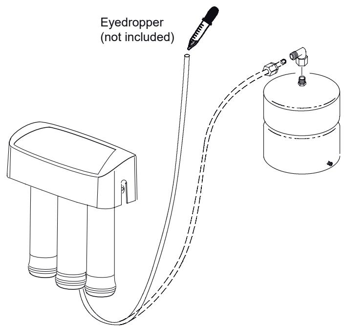
FIG. 21
Step G - Sanitize, Test and Purge System (cont.)
NOTE: Complete the sanitizing procedures on the preceding page before pressure testing.
To pressure test the system, complete the following steps.
- Open the water supply valve to the Reverse Osmosis system.
- Make sure the valve on the water supply fitting (See Fig. 22) is in the open position.
- Purge air from the house plumbing by opening several house faucets. Close faucets when water runs smooth, with no spurting.
- Pressure will start to build in the RO system. In about 2 hours check all fittings and connections. Check for water leaks. Fix leaks if any are found. If problems exist, refer to the troubleshooting chart or call the toll free number below).
NOTE: When the system is first pressurized, water may "spurt" from the faucet air gap hole until air is expelled from the RO system.
Please review the following operating features before using your Reverse Osmosis system:
You will not have filtered water immediately. It may take several hours to fill the storage tank and create maximum flow from the Reverse Osmosis faucet.
Water Pressure from the Reverse Osmosis faucet will be less than your standard faucet
Water will run to the drain while the Reverse Osmosis system is producing water, even if you are not drawing water from the Reverse Osmosis faucet. You may hear a small quantity of water going to the drain at times when water is not being used. This is normal. Water going to the drain will automatically shut off when the storage tank is full.
PURGING THE SYSTEM
To purge the system, complete the following steps.
- Open the Reverse Osmosis Faucet and let water flow through the system for a 24 hour period. Water flow will be a slow trickle at this time.
NOTE: Do not consume water from the RO system until purging is complete. - Close the Reverse Osmosis faucet after the 24 hour purging period is complete.
- When the purging is finished, your Reverse Osmosis system is ready for use.
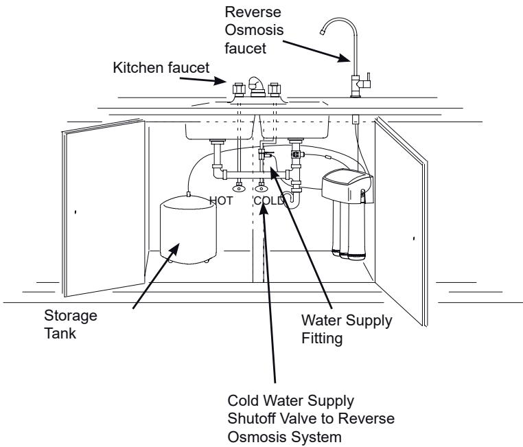
FIG. 22
NOTE: As with all other water system applications, leaks may occur. Because the system pressure builds slowly, leaks may not be immediately apparent. Recheck for leaks 24 hours after purging the system is complete.
How Your RO Water System Works
Introduction: Your Reverse Osmosis (RO) Drinking Water System uses your household water pressure to force water through three filters. Minerals and impurities are filtered out. Delicious tasting drinking water goes to the storage tank-ready for your use. Minerals and impurities are sent down the drain. The following paragraphs will explain in detail how your Reverse Osmosis Drinking Water System works.
Pre-filter (Cartridge 1): Water from the cold supply pipe enters the pre-filter. See Fig. 23. The pre-filter has a replaceable sediment cartridge with activated carbon in its composition. The cartridge reduces taste, odor, sand, silt, dirt, other sediments, and up to the amount of chlorine shown in the specifications.
Reverse Osmosis Membrane Cartridge: Filtered water flows from the pre-filter to the Reverse Osmosis membrane cartridge. See Fig. 23. The Reverse Osmosis cartridge is a tightly wound special membrane. The membrane reduces the dissolved solids and organic matter. High quality product water (about 30ml per minute) exits the Reverse Osmosis membrane cartridge. The product water flows to the storage tank, postfilter or Reverse Osmosis faucet. Drain water, with the dissolved solids and organic matter, is routed to the drain.
Storage Tank: The storage tank holds product water. See Fig. 23. A diaphragm inside the tank holds water pressurized to about half of supply water pressure when the tank is full. This provides fast flow to the Reverse Osmosis faucet. When the tank is empty of water, the pressure at the air valve is 0.35 - 0.48 bar.
Post-filter (Cartridge 2): Water goes through the postfilter before going to the Reverse Osmosis faucet. See Fig. 23. The post-filter is an activated carbon type filter. Any remaining tastes and odors are reduced from the product water. Clean, high quality drinking water is available at the faucet.
Reverse Osmosis Faucet: The sink or countertop faucet has a hand operated knob to dispense drinking water. See Fig. 23.
Shutoff Assembly: The unit has an automatic shutoff system to conserve water. When the storage tank has filled to capacity, and the drinking water faucet is closed, pressure closes the shutoff to stop flow to the drain.
After enough drinking water is used, pressure in the system drops, and the shutoff opens to allow the tank to be refilled. See Fig. 23.
Check Valve: A check valve is located in the Reverse Osmosis manifold above the center cartridge. The check valve prevents a backward flow of product water from the storage tank to drain. A backward flow could damage the Reverse Osmosis Membrane. See Fig. 23.
Flow Control: Water flow to the drain is restricted by the flow control. It maintains the desired flow rate to obtain the highest quality drinking water. The flow control is located inside the elbow fitting on the Reverse Osmosis manifold drain port. See Fig. 23.
How Your RO Water System Works
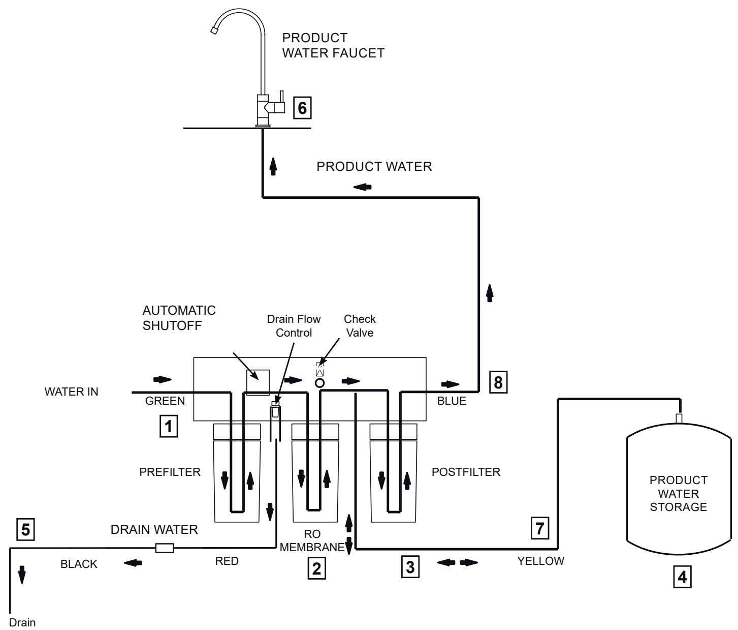
Reverse Osmosis Water Flow Schematic
FIG. 23
Water Flow Description
- Water enters the pre-filter (Cartridge 1). Sand, silt and other sediments are reduced. Chlorine is also reduced. See Fig. 23.
- Water leaves pre-filter and proceeds to the Reverse Osmosis Membrane Cartridge.
- Water enters the Reverse Osmosis membrane. Dissolved solids are reduced.
- Processed water leaves the Reverse Osmosis Membrane and flows to the storage tank.
- Drain water with dissolved solids leaves the Reverse Osmosis membrane and flows to the drain.
- Faucet is activated.
- Processed water leaves the storage tank and flows to the post-filter (Cartridge 2), where it is filtered to ensure fresh taste.
- Water flows to the Reverse Osmosis faucet.
Maintenance
PRE-FILTER/POST-FILTER MAINTENANCE
NOTE: It is recommended to replace the battery, pre-filter and post-filter cartridges at least every 6 months of product water use. Replace more often if they begin to plug with sediment.
The pre-filter and post-filter are replaceable sediment cartridges with activated carbon in their composition. See Fig. 24. You must periodically replace the pre-filter and post-filter cartridge. This will protect the RO membrane from being destroyed by chlorine. It will also prevent the filters from plugging with sediment.
You may notice a slower output of product water as the pre-filter and post-filter build up with sediment. Replace the pre-filter and post-filter cartridges when this occurs. You should replace the battery whenever you replace the cartridges.
RO MEMBRANE CARTRIDGE MAINTENANCE
The Reverse Osmosis cartridge is a tightly wound special membrane. See Fig. 24. The membrane reduces the dissolved solids and organic matter. The life of the Reverse Osmosis membrane cartridge depends mostly on the pH and hardness of the supply water (see Specifications). Cartridge life is shorter with higher pH. For example, if supply water pH is from 6.8 to 7.7, the cartridge may last for well over one year. However, cartridge life may be as short as 6 months if the pH is as high as 8.5 to 10. Higher pH weakens the cartridge membrane and causes pin-hole leaks. It's time to replace the Reverse Osmosis cartridge when the production rate and/or quality of product water drops. Product water may begin to taste different, indicating solids and organics are passing through the Reverse Osmosis membrane. See Reverse Osmosis cartridge replacement.
REVERSE OSMOSIS CARTRIDGE REPLACEMENT
Complete the following steps to replace the cartridges.
NOTE: Do not remove manifold from mounts. Flexing or twisting may damage the manifold.
- Remove (turn to the left) the pre-filter cartridge from the manifold to stop flow to the Reverse Osmosis cartridge.
- Remove the Reverse Osmosis cartridge.
- Remove the post-filter cartridge.
- Discard the cartridges in a proper manner.
- Install new cartridges in reverse order (post-filter, Reverse Osmosis and then pre-filter). Turn cartridges to the right to reattach to the filter heads. Do not overtighten.
- Purge the Reverse Osmosis system. See page 14 for instructions.
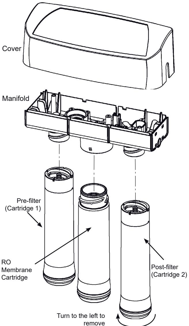
FIG. 24
PRE-FILTER/POST-FILTER CARTRIDGE REPLACEMENT
Complete the following steps to replace the cartridges.
NOTE: Do not remove manifold from mounts. Flexing or twisting may damage the manifold.
- Remove the pre-filter cartridge (turn to the left) from the filter head. Then remove the post-filter cartridge.
- Discard the cartridges in a proper manner.
- Install new cartridges in reverse order (post-filter first, then pre-filter). Turn cartridges to the right to reattach to the filter heads. Do not overtighten.
- Purge the Reverse Osmosis system. See page 14 for instructions.
Maintenance
FLOW CONTROL
The flow control is required for proper operation of the Reverse Osmosis system. See Fig. 25. The flow control, located inside the push-in elbow fitting on the drain port of the system housing, keeps water flowing through the membrane at the required rate. This ensures that the system produces the best quality product water.
Periodically check the flow control to be sure the small hole through it is clean and unrestricted.
If the flow control requires service, review the exploded view in Fig. 25. Assemble and disassemble as shown. If the flow control remains in the manifold when the push-in elbow fitting is removed, you will need to remove the drain port's collet and o-ring, as shown in the next section, to retrieve it.
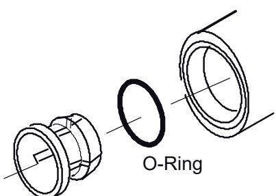
CHANGE COLLET AND O-RING
- Remove the collet and o-ring from the fitting with a small screwdriver. Do not scratch the internal walls of the collet port. See Figs. 26 & 27.
- Clean collet port, lubricate with silicone-based lubricant, and insert the o-ring seal into the bottom of the port. See Figs. 26 & 27.
- Push the collet inward until it locks in place. See Figs.26 & 27.
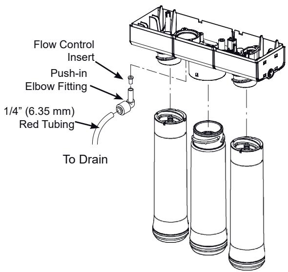
FIG. 25
Push o-ring seal into bottom of port then follow with collet.

Collet
Change Collet and O-ring
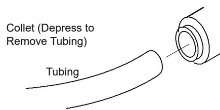
FIG. 26
Disconnect Tubing
FIG. 27
Troubleshooting
| Problem: Chlorine taste and/or odor in the RO product water. | |
| Cause: The level of chlorine in your water supply exceeds maximum limits, and has destroyed the Reverse Osmosis membrane. | Correction: If the water supply contains more than 2.0 ppm of chlorine, additional filtering of the water supply to the Reverse Osmosis is needed. Contact your local water supplier. Correct this condition before doing maintenance on the Reverse Osmosis system. |
| Cause: The pre-filter is no longer reducing chlorine from the water supply. | Correction: Replace the pre-filter, postfilter and Reverse Osmosis membrane cartridges. |
| Problem: Other taste and/or odor. | |
| Cause: Postfilter expended. Cause: Reverse Osmosis membrane cartridge expended. | Correction: Replace the post-filter cartridge. If taste and odor persist, replace the pre-filter cartridge and Reverse Osmosis membrane cartridge. |
| Cause: Contamination in product water storage tank. | Correction: Use sanitizing procedures. Replace pre-filter and post-filter cartridges. |
| Cause: System contamination. | Correction: Sanitize entire system. |
| Problem: System makes product water too slowly. | |
| Cause: Water supply to the Reverse Osmosis system not within specifications. | Correction: Increase water pressure, precondition the water, etc., as needed to conform before doing maintenance on the Reverse Osmosis system. |
| Cause: Pre-filter or Reverse Osmosis membrane cartridges plugged with sediment. | Correction: Replace the pre-filter cartridge. If rate does not increase, replace the post-filter cartridge and Reverse Osmosis membrane cartridge. |
| Problem: System makes lower amount of product water than usual. | |
| Cause: Storage tank air-charge less than 0.35 - 0.48 bar. | Correction: Open Reverse Osmosis faucet and drain tank until flow slows to a drip. Keep faucet open and check tank pressure. If low, pressurize to 0.41 bar. Close faucet to refill the tank. |
| Problem: High total dissolved solids (TDS) in product water | |
| Cause: Water supply to the Reverse Osmosis system not within specifications. | Correction: Increase water pressure, precondition the water, etc., as needed to conform before doing maintenance on the Reverse Osmosis system. Correction: Send treated and untreated water samples to a water analysis lab for testing. It is important to test both the treated and untreated water to determine system performance. If the TDS is not within the system's performance guidelines, replace the pre-filter, post-filter and RO membrane cartridges. |
| Cause: Plugged drain flow control insert | Correction: Replace drain flow control insert. |
| Problem: Continual water flow to drain and low or no water production. | |
| Cause: Missing flow control insert in drain pot. | Correction: Make sure flow control insert is in place. |
| Problem: Water leaks at push connect fittings | |
| Cause: Tubing not cut square. | Correction: Cut tubing square. |
| Cause: Tubing not pushed in all the way. | Correction: Push tubing in all the way. |
| Cause: Tubing nicked. | Correction: Remove tube from connection. Remove nicked portion by cutting tube to shorter length. Reinsert in connection. If removing the drain line, leave in place the elbow fitting that it connects to. |
| Cause: Outer tubing surface finish not smooth. | Correction: Remove tube from connection. Remove problem area by cutting tube to shorter length. Reinsert in connection. If removing the drain line, leave in place the elbow fitting that it connects to. |
Exploded View
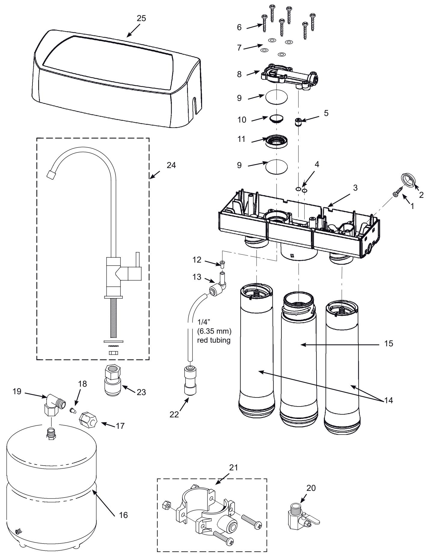
| Key No. | Part No. | Description |
| - | 7333129 | Mounting Hardware Kit (includes 2 ea. of Key Nos. 1 & 2) |
| 1 | ↑ | Screw (2 req'd) |
| 2 | ↑ | Hanger Washer (2 req'd) |
| 3 | 7285368 | Repl. Manifold Assembly (includes Key Nos. 4-11) |
| - | 7333137 | Check Valve Kit (includes Key No. 5 & 2 of Key No. 4) |
| 4 | ↑ | O-ring, Auto. Shutoff Cover (2 req'd) |
| 5 | ↑ | Check Assembly |
| - | 7333145 | Automatic Shutoff Kit (incl. Key No. 8, 4 of Key No. 7 & 6 of Key No. 6) |
| 6 | ↑ | Screw (6 req'd) |
| 7 | ↑ | Washer (4 req'd) |
| 8 | ↑ | Automatic Shut-off Cover Assembly |
| - | 7333179 | Diaphragm Kit (includes Key Nos. 10, 11 & 2 of Key No. 9) |
| 9 | ↑ | Diaphragm (2 req'd) |
| 10 | ↑ | Plunger |
| 11 | ↑ | Spacer Ring |
| - | 7333153 | Flow Control Kit (includes Key Nos. 12 & 13) |
| 12 | ↑ | Flow Control Insert |
| 13 | ↑ | Elbow, Plug-in, 1/4 (6.35 mm) Stem x 1/4 (6.35 mm) Tube |
| Key No. | Part No. | Description |
| 14 | 7306025 | Pre & Post Filter Cartridge* |
| 15 | 7306083 | RO Membrane Cartridge* |
| 16 | 7205326 | Storage Tank |
| - | 7333161 | Tank Connector Kit (includes Key No. 17-19) |
| 17 | ↑ | Nut, 3/8" (9.5 mm) Tubing |
| 18 | ↑ | Insert, 3/8" (9.5 mm) Tubing |
| 19 | ↑ | Connector, 1/4 NPT x 3/8 (6.35 mm) Jaco |
| 20 | DE039 | Water Supply Fitting |
| 21 | 119-8600123 | Drain Clamp |
| 22 | 7208560 | Tubing Union, 1/4" (6.35 mm) Q.C. to 3/8" (9.5 mm) Q.C. |
| 23 | 119-8600092 | Faucet Connector, 7/16" Thd. to 3/8" (9.5 mm)Q.C. |
| 24 | 119-8600096 | Faucet Assembly |
| 25 | 7292080 | Cover, order decal below |
| ■ | 7306106 | Decal, Cover |
| ■ | 7161823 | Tubing, 1/4" (6.35 mm) x 20ft. (6 meters) long, white ▲● |
| ■ | 7157280 | Tubing, 3/8" (9.5 mm) x 20 ft. (6 meters) long, white ▲● |
- Please purchase replacement cartridges from the retailer where you bought your reverse osmosis system.
Not illustrated
Not included.
Tubing lengths for remote installations, direct replacement for colored lengths of tubing.
AEG
Instrukcja obstugi
Model AEG RO
WYKAZ ELEMENTów W ZESTAWIE
SPRAWDZANIE ZAWARTOSCI
INSTALACJA POD ZLEWEM
RYS. 7
ETAP B: INSTALLANIE SYSTEMU POZA KUCHNIA
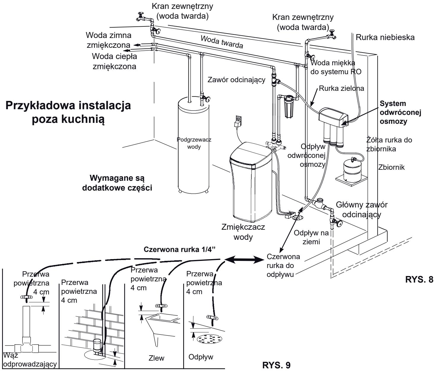
INSTALOWANIE ODPLYWU ZE SZCZELINA POWIETRZNA
WYMIANA FILTRA WSTEPNEG (Pre-filtra) I KONcOWEGO (Post-filtra)