
RKB-850 - Amplifiers ROTEL - Free user manual and instructions
Find the device manual for free RKB-850 ROTEL in PDF.

| Product Type | 8-Channel Power Amplifier |
| Output Power | 50 W per channel (8 channels driven, 8 ohms, 20 Hz - 20 kHz, < 0.1% THD) |
| Number of Channels | 8 channels |
| Input Impedance | 100 kOhms |
| Input Sensitivity | 0.6 V |
| Amplification Gain | 30 dB |
| Frequency Response | 20 Hz - 20 kHz, +0 dB / -1.4 dB |
| Signal-to-Noise Ratio (IHF A) | 108 dB |
| Total Harmonic Distortion | < 0.08% (20 Hz - 20 kHz, 8 ohms) |
| Damping Factor | > 150 |
| Minimum Speaker Impedance | 4 ohms |
| Power Consumption | 150 W operating, 40 W idle, < 0.5 W standby |
| Mains Voltage | 120 V / 60 Hz (USA) or 230 V / 50 Hz (Europe) |
| Dimensions (W x H x D) | 430 x 97 x 424 mm |
| Net Weight | 9.3 kg |
| Connectivity | RCA inputs (4 stereo pairs), preamp output, 12 V trigger input/output, RS-232, speaker terminals |
| Special Features | Manual or automatic power-on (signal sense or 12 V trigger), thermal and overload protection circuit, cooling fans, mono switch, input level adjustment |
| Care and Cleaning | Clean with a dry cloth or vacuum; do not use liquid products |
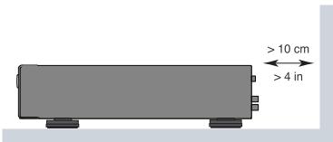
| Safety | Do not open the device; unplug before any intervention; follow ventilation instructions (10 cm at the rear) |
Frequently Asked Questions - RKB-850 ROTEL
User questions about RKB-850 ROTEL
0 question about this device. Answer the ones you know or ask your own.
Ask a new question about this device
Download the instructions for your Amplifiers in PDF format for free! Find your manual RKB-850 - ROTEL and take your electronic device back in hand. On this page are published all the documents necessary for the use of your device. RKB-850 by ROTEL.
USER MANUAL RKB-850 ROTEL
Important Safety Instructions
Notice
The RS232 connection should be handled by authorized persons only.
WARNING: There are no user serviceable parts inside. Refer all servicing to qualified service personnel.
WARNING: To reduce the risk of fire or electric shock, do not expose the unit to moisture or water. Do not expose the unit to dripping or splashing. Do not place objects filled with liquids, such as vases, on the unit. Do not allow foreign objects to get into the enclosure. If the unit is exposed to moisture, or a foreign object gets into the enclosure, immediately disconnect the power cord from the wall. Take the unit to a qualified service person for inspection and necessary repairs.
Read all the instructions before connecting or operating the component.
Keep this manual so you can refer to these safety instructions.
Heed all warnings and safety information in these instructions and on the product itself. Follow all operating instructions.
Clean the enclosure only with a dry cloth or a vacuum cleaner.
Do not use this unit near water.
You must allow a minimum 10cm or 4 inches of unobstructed clearance around the back of the unit.
Do not place the unit on a bed, sofa, rug, or similar surface that could block the ventilation openings. If the unit is placed in a bookcase or cabinet, there must be ventilation of the cabinet to allow proper cooling.
Keep the component away from radiators, heat registers, stoves, or any other appliance that produces heat.
WARNING: The rear panel power cord connector is the mains power disconnect device. The device must be located in an open area that allows access to the cord connector.
The unit must be connected to a power supply only of the type and voltage specified on the side panel. (USA: 120V / 60Hz EC: 230V / 50Hz )
Connect the component to the power outlet only with the supplied power supply cable or an exact equivalent. Do not modify the supplied cable. A polarized plug has two blades, with one wider than the other. A grounding plug has two blades plus a third grounding prong. These are provided for your safety. Do not defeat grounding and/or polarization safety provisions. If the supplied plug does not fit your outlet, please consult an electrician for replacement of the obsolete outlet. Do not use extension cords.
The main plug of the power cordset is a disconnect device of the apparatus. In order to completely disconnect the apparatus from the supply mains, the main plug of the power cordset should be unplugged from the mains (AC) outlet. The power LED indicator will not be lit up to show the power cord is unplugged. The disconnect device shall remain readily operable.
Do not route the power cord where it will be crushed, pinched, bent, exposed to heat, or damaged in any way. Pay particular attention to the power cord at the plug and where the cord exits the back of the unit.
The power cord should be unplugged from the wall outlet during a lightning storm or if the unit is to be left unused for a long period of time.
This apparatus shall be connected to a main socket outlet with a protective earth connection.
Use only accessories specified by the manufacturer.
Use only with a cart, stand, rack, bracket or shelf system recommended by Rotel. Use caution when moving the unit in a stand or rack to avoid injury from a tip-over.
Use Class 2 wiring for speaker connections to ensure proper installation and minimize the risk of electrical shock.
Immediately stop using the component and have it inspected and/or serviced by a qualified service agency if:
The power supply cord or plug has been damaged.
- Objects have fallen or liquid has been spilled into the unit.
The unit has been exposed to rain.
- The unit shows signs of improper operation.
- The unit has been dropped or damaged in any way.

CAUTION
RISK OF ELECTRIC SHOCK DO NOT OPEN

CAUTION: TO REDUCE THE RISK OF ELECTRIC SHOCK, DO NOT REMOVE COVER. NO USER-SERVICEABLE PARTS INSIDE REFER SERVICING TO QUALIFIED SERVICE PERSONNEL.
APPLICABLE FOR USA, CANADA OR WHERE APPROVED FOR THE USAGE
CAUTION: TO PREVENT ELECTRIC SHOCK, MATCH WIDE BLADE OF PLUG TO WIDE SLOT, INSERT FULLY.
ATTENTION:POUR EVITER LES CHOCS ELECTRIQUES, INTRODUIRE LA LAME LA PLUS LARGE DE LA FICHE DANS LA BORNE CORRESPONDANTE DE LA PRISE ET POUSSER JUSQU AU FOND.

This symbol is to alert the user to the presence of uninsulated dangerous voltages inside the product's enclosure that may constitute a risk of electric shock.

This symbol is to alert the user to important operating and maintenance (service) instructions in this manual and literature accompanying the product.

Rotel products are designed to comply with international directives on the Restriction of Hazardous Substances (RoHS) in electrical and electronic equipment and the disposal of Waste Electrical and Electronic Equipment (WEEE). The crossed wheelie bin symbol indicates compliance and that the products must be appropriately recycled or processed in accordance with these directives.

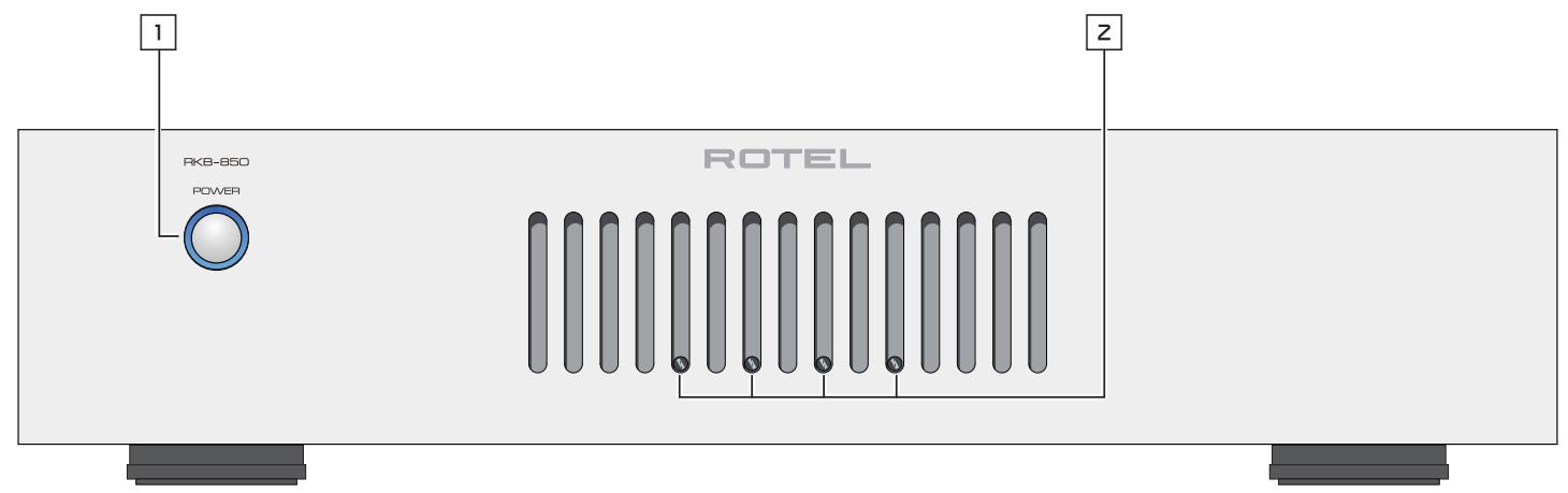
Figure 1: Controls and Connections
Figure 1: Commandes et branchements
Figure 1: Bedienelemente und Anschlusses
Figura 1: Controles y Conexiones
Afbeeling 1: Bedieningselementen en aansluitingen
Figura 1: Controllie connessioni
Figur 1: Kontroller och kontakter
PncyHok 1: OpraHbI ynpaBneHn npa3beMbI
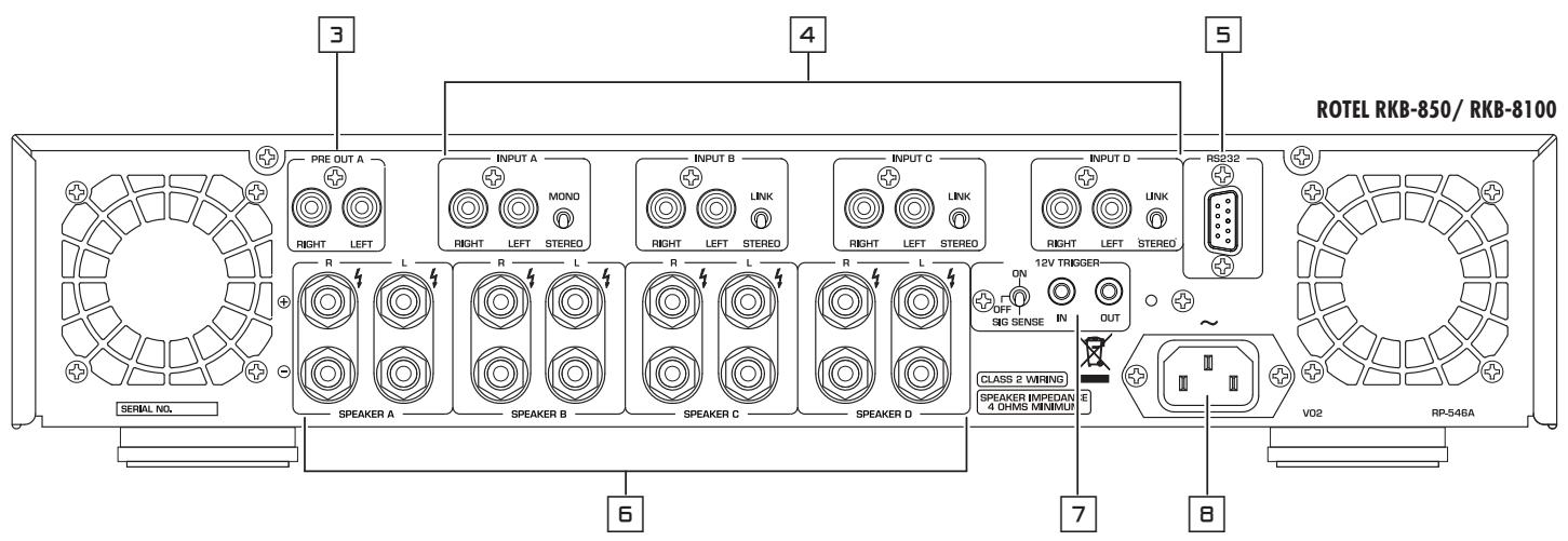
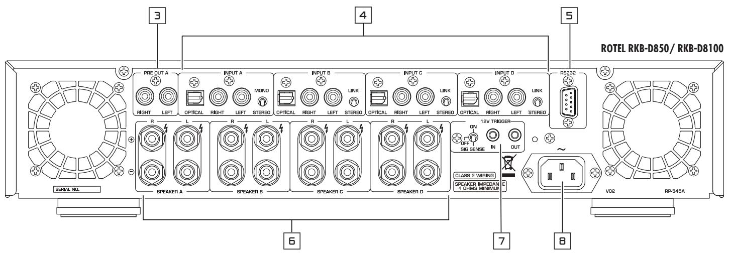
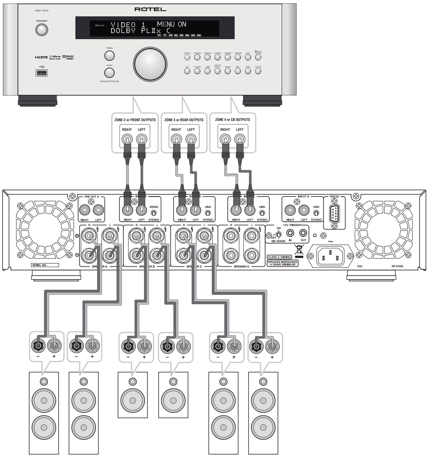
Figure 2: Hook-up Illustration
Figure 2: Schéma de raccordement
Figure 2: Anschlussdiagramm
Figura 2: Ilustración del Conexiónado
Afbeelding 2: Aansluiten Afbeelding
Figura 2: Collegamento ingressi ed uscite
Figur 2: Anslutningar
Picsyok 2: PioocoeiuneHne -npmep
Important Notes
When making connections be sure to:
Turn off all the components in the system before hooking up any components, including loudspeakers.
Turn off all components in the system before changing any of the connections to the system.
It is also recommended that you:
Turn the volume control of the amplifier all the way down before the amplifier is turned on or off.
Remarques importantes
Ipeed nooCoeHHeHnEm:
V BbIKHIOUHTe BCE KOMHOENTbl, BKJIOUaY KOLOHKn.
V BbIKHIOHTe BCE KOMNHOENTb B BaWe CNTeMe, IpexJe Yem QTO-TO B He MeHrTb.
Pekomehdyetca TaKHe:
BbIeCTn rPOMKoCTb ycINlTeYHa MUNHmym, nepeT TEM KAK BKJIIOUaTb NII INBbIKLIQUaTb erO.
Contents
Important Safety Instructions 2
Figure 1: Controls and Connections
Figure 2: Hook-up Illustration
Important Notes 5
About Rotel. 6
A Word About Watts 6
Getting Started 6
A Few Precautions 7
Placement 7
AC Power and Control 7
AC Power Input 7
POWER Switch and Power Indicator 7
Trigger Mode Selector 7
12V Trigger Input and Output 7
Protection Indicator 8
Signal Connections 234 8
RCA Inputs 8
Linking the Inputs 8
Mono Switch 4 8
Input Level Controls 8
Preamp Output 8
Optical Inputs 8
Speaker Outputs 9
Speaker Selection 9
Speaker Wire Selection 9
Polarity and Phasing 9
Speaker Connections 9
RS232 Connector 9
Cooling Fans 9
Troubleshooting 9
Power Indicator Is Not Illuminated 9
No Sound 9
Power Indicator Is Blinking 9
Specifications 10
About Rotel
Our story began over 50 years ago. Over the decades, we have received hundreds of awards for our products and satisfied hundreds of thousands of people who take their entertainment seriously – like you!
Rotel was founded by a family whose passionate interest in music led them to manufacture high-fidelity components of uncompromising quality. Through the years, that passion has remained undiminished and the family goal of providing exceptional value for audiophiles and music lovers, regardless of their budget, is shared by all Rotel employees.
Rotel's engineers work as a close team, listening to, and fine tuning, each new product until it reaches their exacting musical standards. They are free to choose components from around the world in order to make that product the best they can. You are likely to find capacitors from the United Kingdom and Germany, semiconductors from Japan or the United States, while toroidal power transformers are manufactured in Rotel's own factory.
We all have concerns about our environment. And, as more and more electronics are produced it is especially important for a manufacturer to do all it can to engineer products that have a minimum impact on the environment.
At Rotel, we are proud to do our part. We have reduced the lead content in our products by using special lead-free ROHS solder and components. Our engineers continually strive to improve power supply efficiency without compromise to quality. When in standby mode Rotel products use minimal power to meet global Standby Power Consumption requirements.
The Rotel factory is also doing their part to help the environment through constant improvements to product assembly methods for a cleaner and greener manufacturing processes.
All of us at Rotel thank you for buying this product. We are sure it will bring you many years of enjoyment.
A Word About Watts
The RKB-850 and RKB-D850 power output is quoted as 50 watts for each channel, while the RKB-8100 and RKB-D8100 is 100 watts when all eight channels are operating together at full power.
Rotel has chosen to specify the power output in this way because, in Rotel's experience, it gives the truest value of the receiver or amplifier's power capability.
When comparing specifications for different products, you should be aware that power output is often specified in other ways, so you may not be comparing like with like. For example, the power output may be quoted with only one channel operating, giving a higher maximum figure.
A loudspeaker's impedance rating indicates the electrical resistance or load it offers when connected to the amplifier, usually 8 ohms or 4 ohms. The lower the impedance, the more power the speaker will need. In effect, a 4 ohm speaker will require twice as much power as an 8 ohm speaker.
However, Rotel amplifiers are designed to work into any speaker impedance between 8 and 4 ohms, and with all the channels working up to their full power. Because the Rotel design is optimized for use with all channels operating together, Rotel is able to specify the true power output for both channels.
This can be important for your enjoyment, too. When watching movies, it's nice to have the amplifier able to reproduce full power into all the channels at the same time, especially in the case of a volcano exploding!
Getting Started
Thank you for purchasing the Rotel RKB Series Eight Channel Power Amplifier. When used in a high-quality music audio system, your Rotel product will provide years of musical enjoyment.
The RKB amplifiers are high-power amplifiers, providing the highest level of audio performance. A massive power supply, premium components, and Rotel's Balanced Design ensure superb sound quality. High current capability allow the amplifiers to drive the most demanding loudspeakers.
Be aware that the RKB amplifiers are capable of high levels of output power. Make sure that your speakers can handle the power of the amplifier. If in doubt about your speakers, ask your local Rotel audio dealer for advice.
These amplifiers are straightforward in their installation and operation. If you have experience with other stereo power amplifiers, you shouldn't find anything perplexing. Simply plug in the associated components and enjoy.
A Few Precautions
WARNING: To avoid potential damage to your system, turn off ALL the components in the system when connecting or disconnecting the loudspeakers or any associated components. Do not turn the system components back on until you are sure all the connections are correct and secure. Pay particular attention to the speaker wires. There must be no loose strands that could contact the other speaker wires, or the chassis of the amplifier.
Please read this manual carefully. In addition to basic installation and operating instructions, it provides valuable information on various RKB amplifier system configurations as well as general information that will help you get optimum performance from your system. Please contact your authorized Rotel dealer for answers to any questions you might have. In addition, all of us at Rotel welcome your questions and comments.
Save the RKB amplifier shipping carton and all enclosed packing material for future use. Shipping or moving the amplifiers in anything other than the original packing material may result in severe damage to your amplifier.
If included in the box please fill out and send in the owner's registration card. Also be sure to keep the original sales receipt. It is your best record of the date of purchase, which you will need in the event warranty service is ever required.
Placement
The RKB amplifiers generate heat as part of their normal operation. The heat sinks and ventilation openings in the amplifier are designed to dissipate this heat. The ventilation slots in the top and bottom covers must be open. When possible there should be 10cm (4 inches) of clearance around the back side of the chassis. Reasonable airflow in the equipment rack is required to prevent the amplifier from overheating.
Remember the weight of the amplifier when you select an installation location. If you are not using the included rack ears make sure that the shelf or cabinet used can support the RKB. We recommend installing the unit in furniture designed to house audio components. Such furniture is designed to reduce or suppress vibration which can adversely affect sound quality. Ask your authorized Rotel dealer for advice about component furniture and proper installation of audio components.
AC Power and Control
AC Power Input
Your amplifier is configured at the factory for the proper AC voltage in the country where you purchased it, either 120 volts or 230 volts. The AC line configuration is noted on a label on the side panel.
NOTE: Should you move your unit to another country, it may be possible to reconfigure it for use on a different line voltage. Do not attempt to perform this conversion yourself. Opening the enclosure of the unit exposes you to dangerous voltages. Consult a qualified service person or the Rotel factory service department for information.
NOTE: Some products are intended for sale in more than one country and as such are supplied with more than one AC cord. Please only use the one appropriate for your country/region.
Because of its high power rating, the amplifier can draw considerable current. Therefore, it should be plugged directly into a wall outlet. The RKB amplifier must be plugged into a 3-pin polarized outlet. Do not use an extension cord. A heavy duty multi-tap power outlet strip may be used if it (and the wall outlet) is rated to handle the current demanded by the amplifier and all the other components connected to it.
Be sure the POWER SWITCH 1 on the front panel of the amplifier is turned off (in the "out" position). Then, connect the supplied power cord to the Power Connector 8 on the rear of the unit and the AC power outlet.
If you are going to be away from home for an extended period of time such as a month-long vacation, it is a sensible precaution to unplug your amplifier (as well as other audio and video components) while you are away.
POWER Switch and Power Indicator
The power switch is located on the front panel of your amplifier. To turn the amplifier on, push the switch in. The ring around the switch will light up and blink three times, indicating that the amplifier is turned on. To turn the amplifier off, push the button again and return it to the "out" position.
NOTE: Place the self adhesive ring over the light surrounding the power switch if the blue light is too bright.
Trigger Mode Selector
The RKB amplifiers provide three different options for manual or automatic power operation. These modes are selectable using a three-position switch on the back panel as follows:
- With the switch in the OFF position, the amplifier is turned on or off manually using the front panel power switch. Also use this mode if you are using a switched AC outlet to control power to the amplifier.
- With the switch in the SIGNAL SENSE position, the amplifier turns on automatically when an audio signal is detected at the inputs. The amplifier will go into Signal Sense Standby mode and the front Power Indicator will dim after approximately 10 minutes without detecting an audio signal. The front panel POWER SWITCH overrides this function. It must be ON for the signal sensing function to operate. Turning the front panel power switch OFF turns the amplifier off, regardless of whether or not a signal is present.
- With the switch in the ON position, the amplifier is turned on automatically when a 12 volt trigger signal is present at the 3.5mm jack of TRIGGER IN on the rear panel. The amplifier will go into standby mode and the front Power Indicator will dim if the +12 volt signal is not present. The front panel POWER SWITCH overrides this function. It must be ON for the +12V trigger to work. Turning the switch OFF turns the amplifier off, regardless of whether or not a trigger signal is present.
12V Trigger Input and Output
The jack labeled IN is for connecting the 3.5mm mono plug/cable carrying a +12 volt trigger signal to turn the amplifier on and off. To use this feature the toggle switch must be set to the ON position. This input accepts any control signal (AC or DC) ranging from 3 volts to 30 volts.
The jack labeled OUT is for connecting another 3.5mm mono plug/cable to provide a 12 volt trigger signal to other components. The 12 volt output signal is available whenever a +12 volt trigger signal is applied to the IN connector.
NOTE: The maximum current for the trigger out is 10mA.
Protection Indicator
The RKB amplifiers feature thermal and over-current protection circuits that protect against potential damage in the event of extreme or faulty operating conditions.
Most likely, you will never see this protection circuitry in action. However, should a faulty condition arise, the amplifier will shut down and the Power Indicator on the front panel will be blinking.
If this happens, turn the amplifier off, let it cool down for several minutes, and attempt to identify and correct the problem. When you turn the amplifier back on, the protection circuit will automatically reset and the Power Indicator should light up, indicating that the amplifier is operating normal.
In most cases, the protection circuitry activates because of a fault condition such as shorted speaker wires, or inadequate ventilation leading to an overheating condition. In very rare cases, highly reactive or extremely low impedance speaker loads could cause the protection circuit to engage.
If the protection circuitry triggers repeatedly and you are unable to isolate and correct the faulty condition, contact your authorized Rotel dealer for assistance in troubleshooting.
Signal Connections 234
See Figure 2
NOTE: To prevent loud noises that neither you nor your speakers will appreciate, make sure the system is turned off when you make any signal connections.
The RKB amplifier provides standard RCA type input connections as found on nearly all audio equipment.
In addition to the four groups of stereo inputs labeled INPUT A to INPUT D, there is also a pair of PREAMP OUTPUT connections for passing the signal connected to INPUT A to another audio component.
RCA Inputs 4
There are two RCA inputs for each of the four pairs of amplifier channels. These RCA inputs accept audio signals from preamplifiers or surround sound processors. Select high quality audio interconnect cables for best performance.
For each pair of amplifier channels, connect the left channel output of your preamp to the LEFT INPUT on the amplifier. Connect the right channel of your preamp to the RIGHT INPUT. Make sure that the input switch to the right of the RCA inputs is in the STEREO position.
Linking the Inputs
You can link the analog and digital inputs to other channels by moving the LINK/STEREO switch located next to the RCA inputs for Channel B, C and D to the LINK position. When this switch is set to LINK the analog and digital source of the preceding channel will be used for that channel. No source input is required for a channel with LINK enabled. For example when channel C is set to LINK the digital or analog source from channel B will be used.
NOTE: Both the analog and digital input source of INPUT A can be linked to INPUTS B, C and D.
Mono Switch 4
For the channel INPUT A, when the input switch is moved to the MONO position, the left and right RCA inputs are combined and provided to both speakers as a mono signal. Channels linked to INPUT A will also be MONO if the switch is moved to the MONO position.
Input Level Controls
Four controls on the front panel, one for each channel, provide input level adjustments. These allow you to adjust the gain of the amplifier to match source components attached to the amplifier. The INPUT A level control changes the gain of the INPUT A channel; the INPUT B level control changes the INPUT B channel and so on. The controls are not labeled on the front, but when viewed from the front they are from left to right Input D,C,B,A, with input A on the farthest right. To adjust these controls, use a small, flat blade screwdriver. Turn the control clockwise to increase gain. Turn counterclockwise to reduce gain.
Preamp Output
This pair of RCA connections can be used to pass unprocessed input signals to another audio component, for example to "daisy-chain" to another amplifier to drive additional speakers. The input signals connected to the INPUT A connectors is available on the Preamp Output connectors. This is typically used when the amplifier is part of a multi-room system.
NOTE: It is recommended to Daisy Chain a maximum of 8 RKB amplifiers.
NOTE: The MONO switch does not affect the Preamp Output.
Optical Inputs 4
For RKB-D850 and RKB-D8100 Only
There is a digital input labeled OPTICAL for each channel. Connect the OPTICAL PCM outputs of your source component into these sockets. The digital signals will be decoded and played by the RKB-D850 or RKB-D8100. The RKB is capable of decoding PCM signals up to 24 bit, 192kHz .
NOTE: The OPTICAL input will automatically be selected whenever a digital signal is detected. Some source devices will continue to send a signal even when no audio is being transmitted. An example is some CD players will continue to send a signal even if the CD is paused or stopped. In some cases it may be required to power off the digital source device or even disconnect the Optical cable to switch back to the Analog RCA input.
Speaker Outputs
See figure 2
The RKB amplifier has four pairs of speaker connectors, one for each amplifier channel. The eight speaker connectors may be used in many different configurations. The Hook-up Illustration, Figure 2, shows just one example, with the connections for a typical six-speaker system. Here, the remaining two channels are still available to power up to two more speakers as required.
Speaker Selection
We recommend using loudspeakers with a nominal impedance of 4 ohms or higher with the RKB amplifiers. You should not drive more than one pair of speaker for each output channel. Driving more than one set of speakers from an output may damage the RKB amplifier. Speaker impedance ratings are less than precise. In practice, very few loudspeakers will present any problems for the RKB amplifiers. See your authorized Rotel dealer if you have any questions.
Speaker Wire Selection
Use insulated two-conductor stranded wire to connect the RKB amplifier to the speakers. The size and quality of the wire can have an audible effect on the performance of the system. Standard speaker wire will work, but can result in lower output or diminished bass response, particularly over longer distances. In general, heavier wire will improve the sound. For best performance, you may want to consider special high-quality speaker cables. Your authorized Rotel dealer can help in the selection of cables for your system.
Polarity and Phasing
The polarity – the positive/negative orientation of the connections – for every speaker and amplifier connection must be consistent so all the speakers will be in phase. If the polarity of one connection is reversed, bass output will be very weak and stereo imaging degraded. All wire is marked so you can identify the two conductors. There may be ribs or a stripe on the insulation of one conductor. The wire may have clear insulation with different color conductors (copper and silver). There may be polarity indications printed on the insulation. Identify the positive and negative conductors and be consistent with every speaker and amplifier connection.
Speaker Connections
NOTE: The following text describes both binding post and plug-in connections. DO NOT use both connection methods in combination to connect multiple speakers.
Turn off all the components in the system before connecting the speakers. The RKB amplifier has a pair of two color coded binding posts for each channel. These connectors accept bare wire, connector lugs, or dual banana type connectors (except in the European Community countries where their use is not permitted).
Route the wire from the RKB amplifier to the speakers. Give yourself enough slack so you can move the components to allow access to the speaker connectors.
If you are using dual banana plugs, connect them to the wires and then plug into the backs of the binding posts. The thumbscrews of the binding posts should be screwed in all the way (clockwise).
If you are using terminal lugs, connect them to the wires. If you are attaching bare wires directly to the binding posts, separate the wire conductors and strip the insulation from the end of each conductor. Be careful not to cut into the wire strands. Unscrew (turn counterclockwise) the binding post. Place the connector lug or wire around the binding post shaft. Turn the binding post clockwise to clamp the connector lug or wire firmly in place.
NOTE: Be sure there are no loose wire strands that could touch adjacent wires or connectors.
RS232 Connector 5
The RKB amplifier can be controlled via RS232 for integration with automation systems. The RS232 input accepts a standard straight DB-9 Male-to-Female cable.
For additional information on the connections, software, and operating codes for computer control of the RKB amplifier, contact your authorized Rotel dealer.
Cooling Fans
The RKB amplifier includes 2 cooling fans to help exhaust the heat generated by the power supply and amplifier modules. These fans will operate at NORMAL speed when the RKB is powered on and not in STANDBY mode. The fans will automatic switch to HIGH SPEED mode when required by internal thermostat sensors.
NOTE: Depending on the installation location the cooling fans may need to be cleaned periodically to ensure proper ventilation. Please contact your authorized Rotel dealer for more information.
Troubleshooting
Most difficulties in audio systems are the result of incorrect connections, or improper control settings. If you encounter problems, isolate the area of the difficulty, check the control settings, determine the cause of the fault and make the necessary changes. If you are unable to get sound from the RKB amplifier, refer to the suggestions for the following conditions:
Power Indicator Is Not Illuminated
No main power to the RKB amplifier. Check AC power connections at the amplifier and the AC outlet. Check the front panel power switch. Make sure that it is set to the ON position. If using 12V trigger power-on, make sure that a trigger signal is present at rear panel 12V TRIGGER IN connector.
No Sound
If the amplifier is getting AC power, but is producing no sound, check the POWER INDICATOR on the front panel. If blinking, see below. If not, check all of your connections and control settings on associated components.
Power Indicator Is Blinking
The front panel POWER INDICATOR is blinking when the amplifier protection circuits have shut off the amplifier. Typically, this occurs only when the ventilation openings are blocked, when there is faulty speaker wiring, or after a period of extreme use. Turn off the system and wait for the amplifier to cool. Then push the front panel power switch in and out to reset the protection devices. If the problem is not corrected or reoccurs, there is a problem with the system or the amplifier itself.
Specifications
RKB-850
Continuous Power Output 50 watts / channel (8 ch driven)
(20 Hz - 20k Hz, <0.1% THD, 8 ohms)
Total Harmonic Distortion
(20 Hz - 20k Hz, 8 ohms)
Intermodulation Distortion
(60 Hz : 7k Hz, 4:1)
Damping Factor
Input Impedance / Sensitivity
Amplifier Gain
Frequency Response
Signal to Noise Ratio (IHFA)
Crosstalk / Separation
Speaker Impedance
Power Requirements:
USA:
EC:
Power Consumption
BTU (4 ohms, 1/8th power)
Dimensions (W× H× D)
Front Panel Height
Weight (net)
< 0.08%
< 0.08%
150
100k ohms / 0.6 V
30 dB
20 Hz - 20k Hz, + 0 dB/ -1.4 dB
108 dB
60dB
4 ohms minimum
120 Volts, 60 Hz
230 Volts, 50 Hz
150 watts
Idle: 40 watts
Standby: < 0.5 watts
180 BTU/h
430× 97× 424mm
(17 × 3^7 /8 × 16^3 /4 ins)
2U (88.1mm,3^1 / _2 ins)
9.3 kg, 20.5 lbs.
RKB-D850
Continuous Power Output 50 watts / channel (8 ch driven)
(20 Hz - 20k Hz, <0.1% THD, 8 ohms)
Total Harmonic Distortion
(20 Hz - 20k Hz, 8 ohms)
Intermodulation Distortion
(60 Hz : 7k Hz, 4:1)
Damping Factor
Input Impedance / Sensitivity
Amplifier Gain
Frequency Response
Signal to Noise Ratio (IHFA)
Crosstalk / Separation
Speaker Impedance
< 0.08%
150
50k ohms / 0.6V
30 dB
20 Hz - 20k Hz, + 0 dB/ -1.4 dB
108 dB
60dB
4 ohms minimum
Digital Section
Signal to Noise Ratio (IHFA)
Input Sensitivity
Optical Digital Signals
95 dB
-10 dBFS
SPDIF LPCM
(up to 192k Hz 24 bit)
Power Requirements:
USA:
EC:
Power Consumption
120 Volts, 60 Hz
230 Volts, 50 Hz
150 watts
Idle: 45 watts
Standby: < 0.5 watts
180 BTU/h
430× 97× 424mm
(17 × 3^7 /8 × 16^3 /4 ins)
2U (88.1mm,3^1 / _2ins)
9.3 kg, 20.5 lbs.
RKB-8100
Continuous Power Output 100 watts / channel (8 ch driven)
(20 Hz - 20k Hz, < 0.1% THD, 8 ohms)
Total Harmonic Distortion
(20 Hz - 20k Hz, 8 ohms)
Intermodulation Distortion
(60Hz:7kHz,4:1)
Damping Factor
Input Impedance / Sensitivity
Amplifier Gain
Frequency Response
Signal to Noise Ratio (IHFA)
Crosstalk / Separation
Speaker Impedance
Power Requirements:
USA:
EC:
Power Consumption
100 watts / channel (8 ch driven)
< 0.08%
< 0.08%
150
100k ohms / 0.9 V
30 dB
20 Hz - 20k Hz, + 0 dB / -1.4 dB
108 dB
60dB
4 ohms minimum
120 Volts, 60 Hz
230 Volts, 50 Hz
300 watts
Idle: 75 watts
Standby: < 0.5 watts
279 BTU/h
430× 97× 424mm
(17 × 3^7 /8 × 16^3 /4 ins)
2U (88.1 mm, 3 ^1 /2 ins)
9.6 kg, 21 lbs.
RKB-D8100
Continuous Power Output 100 watts / channel (8 ch driven)
(20Hz - 20kHz, < 0.1% THD, 8ohms)
Total Harmonic Distortion
(20 Hz - 20k Hz, 8 ohms)
Intermodulation Distortion
(60 Hz : 7k Hz, 4:1)
Damping Factor
Input Impedance / Sensitivity
Amplifier Gain
Frequency Response
Signal to Noise Ratio (IHFA)
Crosstalk / Separation
Speaker Impedance
< 0.08%
< 0.08%
150
50k ohms / 0.9 V
30 dB
20 Hz - 20k Hz, + 0 dB / -1.4 dB
108 dB
60dB
4 ohms minimum
Digital Section
Signal to Noise Ratio (IHFA)
Input Sensitivity
Optical Digital Signals
95 dB
-7 dBFS
SPDIF LPCM
(up to 192kHz 24 bit)
Power Requirements:
USA:
EC:
Power Consumption
120 Volts, 60 Hz
230 Volts, 50 Hz
300 watts
Idle: 80 watts
Standby: < 0.5 watts
BTU (4 ohms, 1/8th power)
Dimensions (W× H× D)
279 BTU/h
430× 97× 424mm
(17 × 3^7 /8 × 16^3 /4 ins)
Front Panel Height
Weight (net)
2U (88.1mm,3^1 / _2 ins)
9.6 kg, 21 lbs.
ATTENTION: POUR RÉDUIRE LE RISQUE D'ÉLECTROCUTION, NE PAS
RETRER LE CAPOI. IL N'Y A A L'INTERIEUR AUCUNE PIECE
SUSCEPTIBLE D'ETRE MODIFIER PAR L'UTILISATEUR. EN CAS DE PROBLEME, ADRESSEZ-VOUS A UN REPARATEUR AGREE.
APPLICABLE FOR USA, CANADA OR WHERE APPROVED FOR THE USAGE
CAUTION TO PREVENT ELECTRIC SHOCK, MATCH WIDE BLADE
OF PLUG TO WIDE SLOT. INSERT FULLY.
ATTENTION: POUR EVITER LES CHOCS ELECTRIQUES,
INTRODUIRE LA LAME LA PLUS LARGE DE LA FICHE
DANS LA BORNE CORRESPONDUPOUSSEERJUSQUAU FOND.

Signalanschlüsse 234 21
Cinch-Eingänge 21
(20 Hz - 20 kHz, Klirrfactor < 0, 1%, 8 Ohm)
Gesamtkirrfactor (20Hz - 20kHz,8Ohm) < 0,08%
Intermodulationsverzerrung < 0,08 %
(60 Hz: 7 kHz, 4:1)
Dampfungsfactor >150
(20 Hz-20 kHz, 8 ohm)
(20 Hz-20 kHz, 8 ohm)
(20 Hz-20 kHz, 8 ohm)
(20 Hz-20 kHz, 8 ohm)
(20 Hz - 20k Hz, THD < 0.1%, 8 ohm)
(20 Hz - 20k Hz, THD < 0.1%, 8 ohm)
(20 Hz - 20k Hz, THD < 0.1%, 8 ohm)
(20 Hz - 20k Hz, THD < 0.1%, 8 ohm)
Heckolbko CIOB O MOUHOCTN B BaTTax
BbIXoHna MoIcHocTb ycInIteR RKB-850 n RKB-D850 coCTaBJIeT 50 Bt Ha KaJdbI u3 KaHaIIOB, RKB-8100 n RKB-D8100 - 100 Bt Ha KaJdbI u3 KaHaIIOB, pNp BCEx BOCbMn KaHaIax OndHOBpeMeHHo pa6OtaUOuXn Ha NOnHyU MOiUb.
KoMaHnIpeuHaIu3MepeTbBbIXoHHyO MoUHocTb IMeHHo TaKIM MeToOM IOTOMy, UTO NO OByTy Rotel, ToJIbKO OH DaET NCTINHHyO OceHKY BO3MOxHOCTe peCunBepa nn yCunITeIa.
CpaBnBra daHbIe B TexHuecknx XapaKTepeNCTkax pa3JIuHbIX npOdyKTOB, HJxHO IMeTb B BVdu, YTO BbIXoHa MOnHocTb qAcTo N3MepReTc COBCem dpyrIM CnOC6oM, TaK YTO, BO3MOxHo, Bbl PbITaeTecb CpaBnTb MeKdy co6oB coBepHeHPO pa3HbIe Beun.
Hapnimep, BixoHaJMAOuHcTb MoQeT 6bIt npBVeEHa TOfk OJa OndHoro pa6oTaIoUe KaHaJa, UTo N03BoJIeN oNuyuHTb 6OJIe BeICOKn POKa3aTeNb MaKcImaJbHOJ MOUHcTn. BvICOKoKaueCTBeHNbIe 6JOKn NITAHy UcNlNTeJe Rotel rapaHTnpIOT, UTo OHN BbIdaOt pONHyIO 3aRbIeHHyIO MOUHcTb KaK B OJHOM, TaK IN BDbYx KaHaJaX.
IIMpeHaC akyctuecknx CnCTem NOKa3bIbaET, KaKOBO 3JeKtpnueckoe cOnpotNBHeHne IIN HaRpy3Ka, NOkKnUoayMaJ Ha BbIXoJ yCUnlTeN, IN o6bHuO OHa paBHeTc8 OM IIN 4 OMa. Yem HnKe IMpeHaC, TEM 60JIb7a MoUHocTB Notpe6yETc IIN KOLOHKn. B pe3YbTaTe, Akyctuecka CnCTema C cOnpotNBHeHmE 4 OM HyXdaETcB yCUnlTeNe BDbOE 60JIb7e MoUHocTn, Yem 8-OMHaA AC.
Ondako ycniltei Rotor cnpoeKtnoPoBaHbI TaK, TTO6bl pa60TaB C IIO6blIMMpeHaCom KOLOHOK -OT 8 OM do 4 OM, npu BceX kaHaJax OndHOBpeMeHHOBbIdaOuix NOnHyIO MOHOCb. I Tak KaK KOHCTpyKUnn Rotel ONTmIm3NPOBaHbIDnIcNoJIb3OBAHnco BCEMn OndHOBpeMeHHo pa60TaIOUIMn KaHaJaAMn, RotelMOKeT yKa3bIBaTB NCTINHHYIO MOHOCb DnIg OboNX KAHaIOB.
3To MoKjET Oka3aTbCra Ype3BbUaHNO BaxHO IЯBaWnX BneuATNeHn.Пи npocMOTpe KInHOΦnIbMOB JeNaTeJIbHO, YTO6bl YcNlNTeJIb MOr BblaTb NOHJIO MOUcHtB BO BCE KaHaJIb OJHOBpeMeHNO, OO6eHNo KOrJa Ha 3KpaHe npocxOJIT n3BepKeHne ByJkaHa!
Первныешаги
BbIKIyOaTeIb IITaHnI INHdNkATOp NITaHnI
BbIKIIOUaTeJIb pNTAHINpaCNOLOKeH Ha nepeDHeN paHEIn BaIeero ycINITeJIa. Ia BKIIIOUeHnIy cUNITeJIa, HAKMITE Ha bIKIIOUaTeJIb. KoJIbeOBo INHdNKaTOp BOKpyr BbIKIIOUaTeJIa 3aROpITcN i MmHET TpN p3a, NOKa3bIBa, YTO ycINITeJIb BkIOUeH. UTo6bl BbIKIIOUHTb ycINITeJIb, HAKMITE Ha KHOKNy eEe pa3 n BepHInTe ee B NOLOXeHne «BbIKIIOUeHO».
ПРМЕЧИЕ:Есlu севеце cuhezo кльцебоzo унDUKAMOPA BOKpy2 bblIOUчamеля nokaxemcBAm cLUwkom apkum, moXHO 3aIenumb e2O CAMOKJIeuaUMC KOLbUOM.
IpeeknouataIb pexkma 7
Ycnilnten RKB o6ecneuBAoi Tpi pa3nuihbx BO3MOxHocTn Iyra pyHoro nnn ABTomatUeCKOrO BKIOUeHn/ BbIKIOUeHn NITaHn. 3TI pEXMbl BbIbpaIOTc npn POMoOn TpexNo3uONHO ngpeKJIouaTeJHa 3aJeH naHei:
Korda daHbI nepekIooataJIb haxoDITcB noloxeHN OFF, yCunIteJIb BKLIOaIOT I BvIKLOUaIOT BpyHyIO pni NMOOUI KNOPKN Ha nepedHeI NaHEII. TaKke IcNOJ3yIte 3OT peXIM, eCNBaBaIpa03eTKa nepemeHHoro TOKa cHa6ZeHa BvIKIOuataJIem dIy npaBLeHnna oDaey nITaNHa yCUnIteJIb;
Korda nepekliouaTeIb haxoDITcB nOLOXeHn SIGNAL SENSE,ycuIniTeb BkIOUaETcA ABToMaTHeCCKn npu o6HApyXeHn ayDIO cunHaIa H BXoDax. YcuiTeIb nepeJdt B XduIyI pexIM n pepeHna IHNikatOp nItaHn 6ydet TucKlbIM npimepHO uepe3 10 MmHT Pocne TORO, KaCnHaN He 6ydet O6HapxJen. KOnKa Ha nepeDeHn paHEn 6loKnpyet 3Ty fynKcuio. OHa DOnJxHa 6bITB nOLOXeHn ON, UTO6bI cxema o6HapyXeHn CUnHaIpa6Otana. IpeKLIoueHne kONKn B nOLOXeHn OFF oTKIOUaET nItaHne ot yCuInTeJIa, He3ABVCIMO OT TORO, PnCiSyTCTByE tCnHaN IIN Het;
Korda nepekliouaTeIb haxoJITcB nolooJeHn +12VTRIG ON, ycnlntelb BKNIOuaeTcA bTOMaTHUeCKN pRi nOraBLeHn 12-BOIbTOBO rCnHaHa na BxOJe TRIGGER IN Ha 3aDHe nAneHn. YcnIuTeIb nepexoIIT B JdUsn peXIMn IpeNDy INndkaTOp nITaHn6yDet TucKnblm, eCIn 12-BoIbTOBbI cINrHaHnet. KhoNka POWER SWITCH Ha nepeDHe nAneHn 6NoKIpyeT3Ty fynKzHOn. OHa dOJIxHa HaxoJITbcB nOLooJeHn ON, UTo6bI 12-BOIbTOBbI 3aNyCsKaIoUcM cnIRHaPa6tAn. NepeKIOUeHne KhoNkn B noLoXeHne OFF oTKLIouaET nITaHne OT ycnIuTeIa, He3abVCmmo OT TORO, npscytCTBye 3aNyScKaIoUcM cnIRHaI nn Het.
12-B TpnrTepHbBxOaN BbXoD
Ihe3do c mapknpoBkoN IN npedna3Naueho Iy npincoeHnHn Ka6eJc 3,5-MM wTekeporM, HecuIero +12-BoIbTObBiy 3aynCkaOuIy CNrHaN ot npeducnntela nIIN pOuceccopa, BkJIIOUaUoiN i BbIKIOUaUoiN ycInNTeB. YTo6bl peAln3OBaTb 3Ty fynKcuIIO, nepeKnuIHO npeKluOaTeNb DOJIXeH 6bITb yCTaHOBHe N bNOJooJeHne ON. 3TOT BXoD npINHMaET IIO6oB ynpablaOnuI CNrHaJ (npemEnHOrO nIIN NOCToAHnHO TOKa) B dIana3OHe OT 3 Do 30 BoIbT.
THe3do c MapknopBkoj OUT npedHa3NaueHoI npicOeHHeHn eIe odHoro Ka6eIc 3,5-MM uTekePOM, o6ecneuBaIoJero 12-BoIbTOBbI pyCKOBoi CnRHaI dIpyrNx KOMNoHENTB. BbIXoHDHO 12-BOIbTOBbI CnRHaI NOBJIeTCaBCaKII pa3, KorDa 3aynckAioUcn CnRHaI +12 B npiNoJexK THe3dy IN.
PerynpoBKN BxOndbIX ypOBne
Iopctpoky Bxodnoro ypOBnBaO6ecneuBAIoT uebIpe opraHa ynpabEnHnHa nepeDHei paHEni -no OndHomy Iny KaJdoN papbl KaHaNob. OHI nO3BOJIaOT Bam OTperynoBAt Ko3oΦnIeHT pepeDaun ycInlTeN, YTObI OH COOTBeTCTBOBAn dpymKOMPOnHeNTam DaHHNo CnCTembl. PerylanTop ypOBn KaHaNob INPUT A n3MeHReT Ko3oΦnIeHT pepeDaun kaHaNob INPUT A; INPUT B n3MeHReT
Ko3ΦfHnueHT nepeDAuN KauHOB INPUT B, n Tak daJe. OpraHbI ynpabLeHn HnKaK He MapKnipOBAhB Ha nepeDnei NaHei, Ondako BXObl paCnoLoXeHb CIEBa HnPaB0: Input D,C,B,A, npri 3om BxOa A - cnpaba. Iny noDcTpoKn IcNoJIb3yIte He6OJIbUIO TBePTky C pInocKIM WIIzOM. POBepHnTe peryJLTop no YacOBoi CTpeKe Jny UBEInuHn EKo3ΦfHnueHtapeDaun. POBepHnTe peryJLTop npOTINb YacOBoi CTpeKN dny UMeHbSeHn NOKo3ΦfHnueHtapeDaun.
BbIXoN ppeDycnnteIa - Preamp Out 3
3ta npapa pa3bemOB RCA moKet 6bItb nCnoBzObaHa dIy nepeaun Heo6pa6oTaHHbIX BXoHbIX CnHAnOB Ha DpyroayDIO KOMNoHEr, HApnpMep, Ia KaKaAdnPoBAHIN DaOnlHnteBHorO yCnHtEnra, pa6oTaUcero Ha BToPOI KOMPiKeT rPOMKOROBOpHTeN. 3TN BXoHbIe CnHAnB, pIncoEduHeHHBe K KaHAnAM INPUT A, DocTynnbI TAKKe Iy nepeaun Ha BixOdbi Preamp Out. O6bHuO OHn IcNoB3yOTc KOrDa ycHnTeB YBnEeTcyaCTbIO MyJbTnPyMHO cnCTeMbI.
ПРИМЕЧАНЕ: Реком endуем с coe duяmb zuenouкон He 6oJIe 8 ycuIumeneu muna RKB.
ПРМЕЧАHИЕ: Пеклочаleteь MONО не с��ем на Bavховы Preamp Out.
Ontnueckne BxOdbI
ToIbko OJRA RKB-D850 u RKB-D8100
Bo3MOxHbIe HeNCpPaBHOCTN
Болшнистwo npo6lemВaydno cnstemax nO8BJIOTcBpe3yIbTaTe pIoXnN IIN HeBephIXx coeHNHeHIn,IIIN HenpaBnIbHbIX ynpaBnIouxn HAcTpoE.K EcIn Bbl cToKHyIinCb c npo6IeMaMn,ИЗОЛурTuTe O6NaCTbN Bo3HnKHOBeHn, npoBepbTe HacTpoIKN,OnpeDenIte pniuHny HeNCpRaBHOCTn IN CdeJaTe Heo6xOdMbIe I3MeHEnH.N.EcIn Bbl He Me MoJTe Do6NbC3ByKa OT CBOero ycInntela RKB-1508, o6paTntecb K cobetamДЯ cnedeYIOxN cnTuaIcn:
HnDnKatop nntaHa nepeDne naHeNe He CBeTtC8
Ha ycnilteB RKB he noaetcnaTahne. PnpobepbTe ceteBle pa3bembl Ha ycnilteIe n B po3etke. PnpobepbTe bIKIOUaTeB nITAHnHa nepeDneH naHEnn. Y6eINTEcb, yTO OH haxOOnTCB NPOLOKeHN ON. EcIn nCpOJIb3yETcB BKIOUeHnE 12-B 3aynckAIOUM CmIHANOM, Y6eINTEcb, yTO 3aynckAIOUcN CmIHAN pncytCTbYET B rHe3de 12V TRIG IN Ha 3aNDne naHEnn.
Het 3Byka
EcnHa yCnInTeB noJaetc ceteBoe HapPjaKeHne, Ho 3ByK He BocpnO3BODntc, npOBepbTe nHdNkAtop 3aunTbI PROTECTION Ha nepeDnei naHei. Ecn OH Mnraet, nepexoDnte K cnEduyUoSeMy pa3Deny. Ecn Het, npOBepbTe BCE BaAsn BXoDhble pa3bEmbl N HacTroKn Yu npabLeHn Dna NpOcOeDnHeHnOro o6OpuyDoBaHn.
ИнданkaTop зашит biomraet
INndkaTOp 3aunTb PROTECTION INDICATOR Ha nepeedne nanele 3aropaetc, KOrda cxembl 3aunTb OTKlnouHnI yCunInTeB. O6bUHO, 3TO npOcnXoDIT, KOrda ycInTeB nepepercen I3-3a 6JoknPOBaHnI BeHTnlaOnOHbIX OTBepCTN, KOrda HnepaBnBNo IOdoceHNH rPOMKOrOBOpTeB nII NocLe nepiOnDa pa60tbl Ha maksmaJIbHO MOuHcTb. BbIKIOuHte CnCTeMy nIOdoxJnte, YTo6bl ycInTeB OCTbl. 3aTEM hAKMITE n OTOXMITE KONKY BKIOUHeHnI PNTaHnI Ha nepeedne pAnEHI, YTo6bl c6pocNTb xCebM 3aUnTb.EcNI npO6Lema He yctpaHena HnI npOABJIeTcCHOBA, 3HaUHT, OTKa3aJa Ba7a CnCTeMa nI cam ycInTeB.
Texhnuechne xapaKtepncnkn
RKB-850
2-11-4, Nakane, Meguro-ku,
Tokyo, 152-0031
Japan
Rotel of America
54 Concord Street
North Reading, MA 01864-2699
USA
Phone: +1 978-664-3820
Fax: +1 978-664-4109
Rotel Europe
Dale Road
Worthing, West Sussex BN11 2BH
England
Phone: +44 (0)1903 221 710
Fax: +44 (0)1903 221 525
Rotel Deutschland
- Important Safety Instructions
- Notice
- CAUTION
- APPLICABLE FOR USA, CANADA OR WHERE APPROVED FOR THE USAGE
- Important Notes
- When making connections be sure to:
- It is also recommended that you:
- Remarques importantes
- Ipeed nooCoeHHeHnEm:
- Pekomehdyetca TaKHe:
- Contents
- About Rotel
- A Word About Watts
- Getting Started
- A Few Precautions
- Placement
- AC Power and Control
- AC Power Input
- POWER Switch and Power Indicator
- Trigger Mode Selector
- 12V Trigger Input and Output
- Protection Indicator
- Signal Connections 234
- RCA Inputs 4
- Linking the Inputs
- Mono Switch 4
- Input Level Controls
- Preamp Output
- Optical Inputs 4
- Speaker Outputs
- Speaker Selection
- Speaker Wire Selection
- Polarity and Phasing
- Speaker Connections
- RS232 Connector 5
- Cooling Fans
- Troubleshooting
- Power Indicator Is Not Illuminated
- No Sound
- Power Indicator Is Blinking
- Specifications
- RKB-850
- RKB-D850
- RKB-8100
- RKB-D8100
- Heckolbko CIOB O MOUHOCTN B BaTTax
- Первныешаги
- BbIKIyOaTeIb IITaHnI INHdNkATOp NITaHnI
- IpeeknouataIb pexkma 7
- 12-B TpnrTepHbBxOaN BbXoD
- PerynpoBKN BxOndbIX ypOBne
- BbIXoN ppeDycnnteIa - Preamp Out 3
- Ontnueckne BxOdbI
- Bo3MOxHbIe HeNCpPaBHOCTN
- HnDnKatop nntaHa nepeDne naHeNe He CBeTtC8
- Het 3Byka
- ИнданkaTop зашит biomraet
- Texhnuechne xapaKtepncnkn
Brand : ROTEL
Model : RKB-850
Category : Amplifiers