
DHE1146A - Basket DE DIETRICH - Free user manual and instructions
Find the device manual for free DHE1146A DE DIETRICH in PDF.
| Product type | Range hood |
| Brand | DE DIETRICH |
| Model | DHE1146A |
| Installation version | External evacuation or recirculation (with charcoal filter) |
| Adjustable depth | 275 to 360 mm |
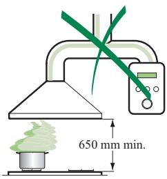
| Minimum installation height | 650 mm above the cooking surface |
| Air outlet diameter | 120 mm |
| Number of speeds | 3 speeds (1, 2, 3) + intensive mode |
| Control type | Buttons with digital display (LED) |
| Lighting | Halogen lamp 20 W (replaceable) |
| Grease filters | Self-supporting metal, dishwasher-safe (every 2 months) |
| Odor filters | Activated carbon, not washable, replace every 4 months |
| Intensive mode | 10 minutes at maximum speed, automatic return to previous speed |
| Automatic shut-off | 30-minute mode (shuts off after 30 minutes of operation) |
| Power supply | 220-240 V, 50 Hz |
| Included accessories | Mounting brackets, safety brackets, plugs, screws, drilling template |
| Exterior cleaning | Damp cloth and mild detergent |
| Spare parts available | Grease filters, charcoal filters, halogen lamps |
| After-sales service | 0892 02 88 04 |
| Website | www.de-dietrich.com |
Frequently Asked Questions - DHE1146A DE DIETRICH
User questions about DHE1146A DE DIETRICH
0 question about this device. Answer the ones you know or ask your own.
Ask a new question about this device
Download the instructions for your Basket in PDF format for free! Find your manual DHE1146A - DE DIETRICH and take your electronic device back in hand. On this page are published all the documents necessary for the use of your device. DHE1146A by DE DIETRICH.
USER MANUAL DHE1146A DE DIETRICH
REPLACEMENT FILTRE AU CHARBON ACTIF
Dear valued customer,
To discover a De Dietrich product is to experience the range of unique emotions which only high-value items can produce.
The attraction is immediate, from the moment you set eyes on the product. The sheer quality of the design shines through thanks to the timeless style and outstanding finishes which make each appliance an elegant and refined little masterpiece in its own right, each in perfect harmony with the others.
Next, comes the irresistible urge to touch it. De Dietrich's design makes extensive use of robust and prestigious materials. The accent is placed firmly upon authenticity.
By combining state-of-the-art technology with top quality materials, De Dietrich produces beautifully crafted products to help you get the most from the culinary arts, a passion shared by all lovers of cooking and fine food.
We hope that you enjoy using this new appliance and we would love to receive your suggestions and to answer any questions you may have. Please feel free to contact our customer service department via our website.
To benefit from the many advantages offered by the brand, we recommend that you register your product at: www.de-dietrich.com.
Thank you for choosing a De Dietrich product.
De Dietrich
You can find a full range of information about the brand at www.de-dietrich.com
Visit the De Dietrich Gallery, 6 rue de la Pepinière (Paris eighth district)
Open from Tuesday to Saturday from 10 am to 7 pm
Customer service department: 0892 02 88 04
www.dedietrich-electromenager.com
As part of our commitment to constantly improving our products, we reserve the right to make changes to them based on advances to their technical, functional and/or aesthetic properties.

Important:
Before installing and using your appliance, please read this Installation and Usage
Guide carefully, as it will allow you to quickly familiarise yourself with its operation.
The Instructions for Use apply to several versions of this appliance. Accordingly, you may find descriptions of individual features that do not apply to your specific appliance.
INSTALLATION
- The manufacturer will not be held liable for any damages resulting from incorrect or improper installation.
- The minimum safety distance between the cooker top and the extractor hood is 650~mm (some models can be installed at a lower height, please refer to the paragraphs on working dimensions and installation).
- Check that the mains voltage corresponds to that indicated on the rating plate fixed to the inside of the hood.
- For Class I appliances, check that the domestic power supply guarantees adequate earthing.
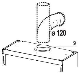
Connect the extractor to the exhaust flue through a pipe of minimum diameter 120~mm . The route of the flue must be as short as possible.
- Do not connect the extractor hood to exhaust ducts carrying combustion fumes (boilers, fireplaces, etc.).
- If the extractor is used in conjunction with non-electrical appliances (e.g. gas burning appliances), a sufficient degree of aeration must be guaranteed in the room in order to prevent the backflow of exhaust gas. The kitchen must have an opening communicating directly with the open air in order to guarantee the entry of clean air. When the cooker hood is used in conjunction with appliances supplied with energy other than electric, the negative pressure in the room must not exceed 0.04 mbar to prevent fumes being drawn back into the room by the cooker hood.
- In the event of damage to the power cable, it must be replaced by the manufacturer or by the technical service department, in order to prevent any risks.
USE
- The extractor hood has been designed exclusively for domestic use to eliminate kitchen smells.
- Never use the hood for purposes other than for which it has been designed.
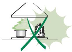
- Never leave high naked flames under the hood when it is in operation.
- Adjust the flame intensity to direct it onto the bottom of the pan only, making sure that it does not engulf the sides.
- Deep fat fryers must be continuously monitored during use: overheated oil can burst into flames.
- Do not flambe under the range hood; risk of fire
- This appliance is not intended for use by persons (including children) with reduced physical, sensory or mental capabilities, or lack of experience and knowledge, unless they have been given supervision or instruction concerning use of the appliance by a person responsible for their safety.
Children should be supervised to ensure that they do not play with the appliance. - "CAUTION: Accessible parts may become hot when used with cooking appliances."
MAINTENANCE
- Switch off or unplug the appliance from the mains supply before carrying out any maintenance work.
- Clean and/or replace the Filters after the specified time period (Fire hazard).
- Clean the hood using a damp cloth and a neutral liquid detergent.
The symbol on the product or on its packaging indicates that this product may not be treated as household waste. Instead it shall be handed over to the applicable collection point for the recycling of electrical and electronic equipment. By ensuring this product is disposed of correctly, you will help prevent potential negative consequences for the environment and human health, which could otherwise be caused by inappropriate waste handling of this product. For more detailed information about recycling of this product, please contact your local city office, your household waste disposal service or the shop where you purchased the product.
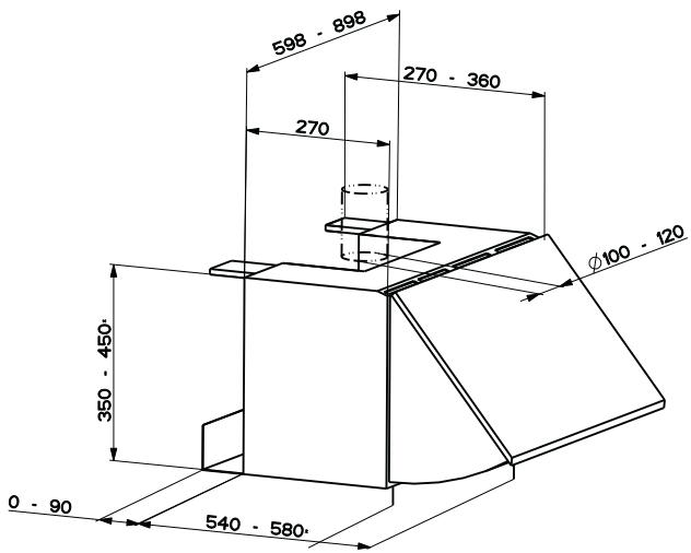
Dimensions
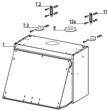
Components
| Ref. | Q.ty | Product Components |
| 1 | 1 | Hood Body, complete with :Controls, Light, Blower, Filters |
| 9 | 1 | Flangeø120 mm |
Ref. Q.ty Installation Components
7.2 2 Hood Body Fixing Brackets
7.3 2 Safety Squares
11 6 Wall Plugs
12a 6 Screws
Q.ty Documentation
1 Instruction Manual
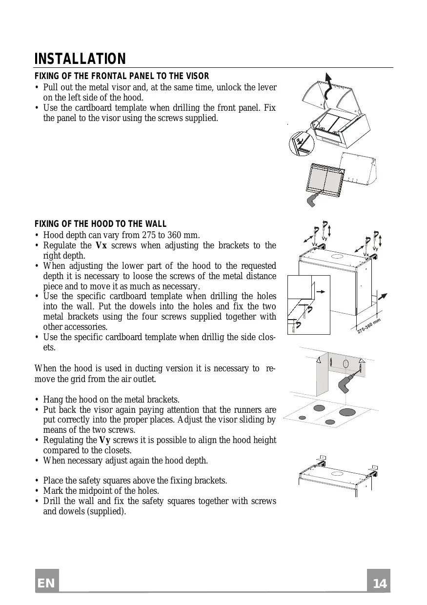
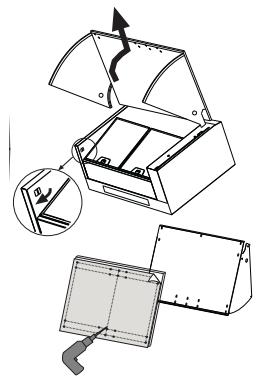
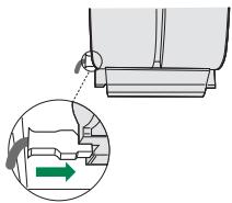
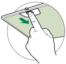
FIXING OF THE FRONTAL PANEL TO THE VISOR
- Pull out the metal visor and, at the same time, unlock the lever on the left side of the hood.
- Use the cardboard template when drilling the front panel. Fix the panel to the visor using the screws supplied.
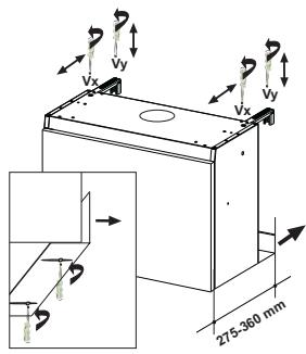
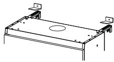
FIXING OF THE HOOD TO THE WALL
- Hood depth can vary from 275 to 360mm .
- Regulate the Vx screws when adjusting the brackets to the right depth.
- When adjusting the lower part of the hood to the requested depth it is necessary to loosen the screws of the metal distance piece and to move it as much as necessary.
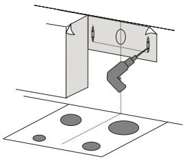
- Use the specific cardboard template when drilling the holes into the wall. Put the dowels into the holes and fix the two metal brackets using the four screws supplied together with other accessories.
- Use the specific cardboard template when drilling the side closets.
When the hood is used in ducting version it is necessary to remove the grid from the air outlet.
- Hang the hood on the metal brackets.
- Put back the visor again paying attention that the runners are put correctly into the proper places. Adjust the visor sliding by means of the two screws.
- Regulating the Vy screws it is possible to align the hood height compared to the closets.
- When necessary adjust again the hood depth.
- Place the safety squares above the fixing brackets.
- Mark the midpoint of the holes.
- Drill the wall and fix the safety squares together with screws and dowels (supplied).
Connections
DUCTED VERSION AIR EXHAUST SYSTEM
When installing the ducted version, connect the hood to the chimney using either a flexible or rigid pipe 120mm , the choice of which is left to the installer.
Fix the pipe in position using sufficient pipe clamps (not supplied).
- Remove any activated charcoal filters.
AIR OUTLET IN RECYCLING VERSION
- Make sure that the hood body has been completely fixed.
- Make sure that hood is equipped with charcoal filters.
ELECTRICAL CONNECTION
- Connect the hood to the mains through a two-pole switch having a contact gap of at least 3mm .
- Remove the grease filters (see paragraph Maintenance) being sure that the connector of the feeding cable is correctly inserted in the socket placed on the side of the fan.
Control Board
| Key | Function | Display |
| A | By pressing this key turn on and off lighting. Press once to turn the dimmer light on. Press twice to turn the normal light setting on. Press again to turn off the lighting. | - |
| B | Increases the suction speed | 1 - 2 - 3 |
| By pressing this key for 3 seconds activate the intensive speed. This speed has been timed at 10 minutes. After that time the system activates automatically the latest selected speed. This function is suitable for cooking conditions when vapours and smells are of the utmost emission. | H appears. The spot down on the right side flashes | |
| C | Display | - |
| D | Decreases the suction speed | 3 - 2 - 1 |
| By pressing this key for 3 seconds turn on and off 30 minute delay feature which runs the hood for 30 minutes and automatically shuts the hood off. | Indicates the selected speed. The spot down on the right side flashes | |
| E | Switches the extractor motor on and off at the latest selected speed | Indicates the selected speed |
A —

B

10
C

D—

E

Grease filters
CLEANING METAL SELF- SUPPORTING GREASE FILTERS
- The filters must be cleaned every 2 months of operation, or more frequently for particularly heavy usage, and can be washed in a dishwasher.
- Remove the filters one at a time by pushing them towards the back of the group and pulling down at the same time.
- Wash the filters, taking care not to bend them. Allow them to dry before refitting.
- When refitting the filters, make sure that the handle is visible on the outside.
Activated charcoal filter (Recirculation version)
These filters are not washable and cannot be regenerated, and must be replaced approximately every 4 months of operation, or more frequently with heavy usage.
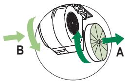
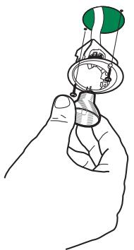
REPLACING THE ACTIVATED CHARCOAL FILTER
- Remove the metal grease filters
- Remove the saturated activated charcoal filter as shown (A).
- Fit the new filters (B).
- Replace the metal grease filters.
Lighting
LIGHT REPLACEMENT
20 W halogen light.
- Remove the 2 screws fixing the Lighting support, and pull it out of from the Hood.
- Extract the lamp from the Support.
- Replace with another of the same type, making sure that the two pins are properly inserted in the lamp holder socket holes.
- Refit the Support, fixing it in place with the two screws removed as above.
TROUBLESHOOTING
| SYMPTOMS | SOLUTIONS |
| The hood is not working... | Ensure that: · The power is not cut off. · A speed has been selected. |
| The hood is not operating effectively... | Ensure that: · The selected motor speed is sufficient for the quantity of smoke and vapours to be cleared. · The kitchen is sufficiently ventilated to allow for fresh air intake. · The carbon filter is not worn (hood operating in recycling mode). |
| The hood stopped work-ing | Ensure that: · The power is not cut off. · The single-pole cut-off device was not activated. |
To preserve your appliance, we recommend that you use Clearit cleaning products.

Professional expertise serving individuals
Clearit offers you professional products and solutions designed for the daily care of your household appliances and kitchens.
They are on sale at your regular retailer, along with a complete line of accessories and consumable products.