TOPSTONE NEO - Electric mountain bike CANNONDALE - Free user manual and instructions
Find the device manual for free TOPSTONE NEO CANNONDALE in PDF.

User questions about TOPSTONE NEO CANNONDALE
0 question about this device. Answer the ones you know or ask your own.
Ask a new question about this device
Download the instructions for your Electric mountain bike in PDF format for free! Find your manual TOPSTONE NEO - CANNONDALE and take your electronic device back in hand. On this page are published all the documents necessary for the use of your device. TOPSTONE NEO by CANNONDALE.
USER MANUAL TOPSTONE NEO CANNONDALE
Owner's Manual Supplement

WARNING
READ THIS SUPPLEMENT AND YOUR CANNONDALE BICYCLE OWNER'S MANUAL. Both contain important safety information. Keep both for future reference.
Safety Messages
In this supplement, particularly important information is presented in the following ways:

WARNING
Indicates a hazardous situation which, if not avoided, may result in death or serious injury.
NOTICE
Indicates special precautions that must be taken to avoid damage.
The following symbols are used in this manual:
| Symbol | Name | Description |
| NGLI-2 synthetic grease | NGLI-2 synthetic grease | Apply NGLI-2 synthetic grease. |
| Carbon gel | Carbon gel | Apply carbon gel (friction paste) KF115/ |
| 2 | Medium-strength removable thread lock | Apply Loctite® 242 (blue) or equivalent. |
Cannondale Supplements
This manual is a "supplement" to your Cannondale Bicycle Owner's Manual.
This supplement provides additional and important model specific safety, maintenance, and technical information. It may be one of several important manuals/supplements for your bike; obtain and read all of them.
Please contact your Authorized Cannondale Dealer immediately if you need a manual or supplement, or have a question about your bike. You may also contact us using the appropriate country/region/location information.
You can download Adobe Acrobat PDF versions of any manual/supplement from our website: http://www.cannondale.com.
Contacting Cannondale
Cannondale USA
Cycling Sports Group, Inc.
1 Cannondale Way,
Wilton CT, 06897, USA
1-800-726-BIKE (2453)
Cycling Sports Group Europe B.V
Mail: Postbus 5100
Visits: Hanzepoort 27
7570 GC, OLDENZAAL, Netherlands
Tel: +41 61 551 14 80
Fax:+31541514240
International Distributors
Consult our website to identify the appropriate Cannondale Dealer for your region.
CONTENTS
Identification 4
Safety Information. 5-12
Key. 13
Technical Information. 14-31
Replacement Parts. 32
E-Bike Maintenance. 34-36
Your Cannondale Dealer
To make sure your bike is serviced and maintained correctly, and that you protect applicable warranties, please coordinate all service and maintenance through your Authorized Cannondale Dealer.
NOTICE
Unauthorized service, maintenance, or repair parts can result in serious damage and void your warranty.
Drive System

WARNING
MANUFACTURER'S INSTRUCTIONS - In addition to this supplement, you must read and follow the manufacturer's instructions for all components of the drive-assist system:
Drive Unit
Battery
Display/Control Unit
Charger
Manufacturers' instructions contain important operations, service and maintenance information.
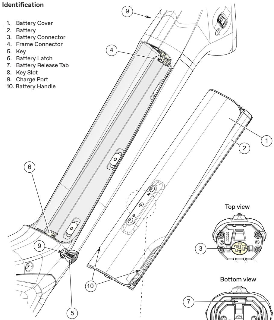
IDENTIFICATION
Parts of Your E-Bike
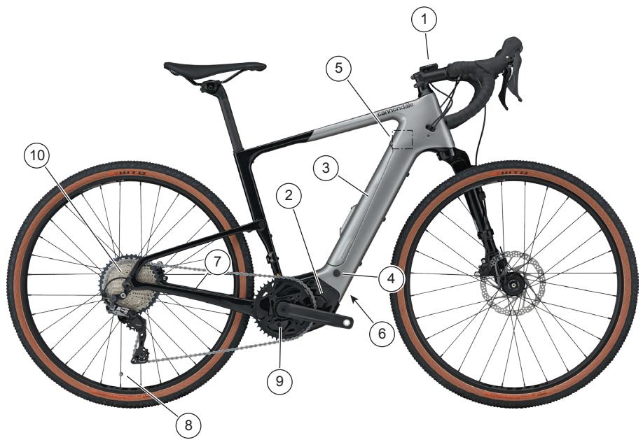
Identification
- Drive Display
- Drive Unit
- Battery Cover
-
Battery Key
-
Charge Port
- Frame Serial Number
- Wheel Sensor
- Spoke Magnet
Actual bike appearance will differ.
- Front Chainrings
- Rear Cassette
Serial Number
The serial number is located on downtube.
It is a 7-character code. Use this serial
number to register your bike.
To register your bike: go to the
Product Registration section of our
website at www.cannondale.com
Record YOUR Serial Number here:
SAFETY INFORMATION
Intended Use
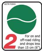
The intended use of all models is ASTM CONDITION 2, General Purpose Riding
What is an E-Bike?
Electric bikes, also known as "E-Bikes" are bicycles equipped with an electric pedal assist drive system. An E-Bike IS NOT a moped or motorcycle. E-Bike share components common with pedal-only bikes.
What is a Drive System?
The drive-assist system consists of a drive unit, a battery, a computer control, and various electronic components (harness wires, sensors, and switches). There are many different drive-assist systems for differing uses and bike types. Likewise there are various drive-assist system manufacturers (Shimano, BOSCH, Bafang, Yamaha, etc.)
How does the Drive System work?
It is important to know that when the drive-assist system is turned ON, the drive unit engages to provide power only while you are pedaling.
The amount of power provided by the drive unit depends on your pedaling force and the assistance mode/level you set with the handlebar control unit. At anytime, if you stop pedaling, the drive-assist will disengage.
In all modes/levels, the drive-assist system power reduces progressively and cuts off as the bike reaches a the maximum allowable speed. The drive-assist re-engages when speed drops below the maximum allowable speed as long as the pedals are turning.
Whenever the drive-assist system is turned OFF, you can pedal the bike normally. The drive system will not engage.

WARNING
Understand your bike, its drive-assist system and the intended use of both. Using your bike the wrong way is dangerous.
Please read your Cannondale Bicycle Owner's Manual for more information about Intended Use and Conditions 1-5.
Servicing

WARNING
This supplement may include procedures beyond the scope of general mechanical aptitude.
Special tools, skills, and knowledge may be required. Improper mechanical work increases the risk of an accident. Any bicycle accident has risk of serious injury, paralysis or death.
To minimize risk we strongly recommend that owners always have mechanical work done by an Authorized Cannondale Dealer.
Important Composites Message

WARNING
Your bike (frame and components) is made from composite materials also known as "carbon fiber."
All riders must understand a fundamental reality of composites. Composite materials constructed of carbon fibers are strong and light, but when crashed or overloaded, carbon fibers do not bend, they break.
For your safety, as you own and use the bike, you must follow proper service, maintenance, and inspection of all the composites (frame, stem, fork, handlebar, seat post, etc.) Ask your Cannondale Dealer for help.
We urge you to read PART II, Section D. "Inspect For Safety" in your Cannondale Bicycle Owner's Manual BEFORE you ride.
You can be severely injured, paralyzed or killed in an accident if you ignore this warning.
Inspection & Crash Damage Of Carbon Frames/Forks

WARNING
After A Crash Or Impact:
Inspect frame carefully for damage. See PART II, Section D. Inspect For Safety in your Cannondale Bicycle Owner's Manual.
Do not ride your bike if you see any sign of damage, such as broken, splintered, or delaminated carbon fiber.
Any of the following may indicate a delamination or damage:
An unusual or strange feel to the frame
- Carbon which has a soft feel or altered shape
- Creaking or other unexplained noises,
Visible cracks, a white or milky color present in carbon fiber section
Continuing to ride a damaged frame increases the chances of frame failure, with the possibility of injury or death of the rider.
No Child Seats or Trailers

WARNING
Child seats and trailers or racks can not be used and are not allowed to be used with your Cannondale E-Bike.
Compliance/Regulation

WARNING
YOU MUST OBEY ALL LOCAL LAWS & REGULATORY REQUIREMENTS - It is your responsibility to identify and follow all local laws and regulations necessary for legal compliance. Compliance with local regulation is critical to the safety of a rider and others where the bike is used.
Here are some important specifications related to compliance with local laws:
VEHICLE CLASS - A definition (California, USA) of the different types of E-Bikes, E-Bike labeling and legal use areas, including any required additional equipment, registration, and applicable rider age restrictions.
VEHICLE CATEGORY - A definition of the European Union of the different types of E-Bikes, who and where they may be used, necessary additional equipment such as lighting and signaling devices as well as any necessary insurance and licensing.
MINIMUM OPERATOR AGE - A minimum age require-ment for a rider of the E-Bike. This restriction as well as speed and additional equipment requirements (light, helmets, license plates, signal lamps, etc.)
Follow any state or local laws for any minimum age restrictions for E-Bikes.
Ask your local Authorized Cannondale Dealer for more information about operating an electrically assisted pedal bicycle in your area.
Operation

WARNING
Always wear an approved bicycle helmet and all other protective gear (e.g. gloves, pads, and cycling shoes).
Importance of practice & rider training - before you ride this bike, practice riding in a safe area free from hazards. Take time to learn to bike's controls and performance. Practice the controls and gain the experience necessary to avoid the many hazards you will encounter while riding.
Do not ride "hands-off - Keep your hands on the handlebars when riding the bike. If you remove your hands from the handlebar while riding, you can lose control of the bicycle and crash.
Changing the assistance level while riding: Changing the drive-assistance level while riding will increase or decrease the acceleration of the bike. You should anticipate this change in speed and react appropriately depending on the riding conditions. (Such as on slippery trails, tight turns, or unstable or uneven surfaces). Set assistance level to "eco" (lowest assist) or "off" before descending technical trails, (e.G. Tight downhill switchbacks).
When not riding: Turn the drive system off to prevent unauthorized use.
Do not ride the e-bike without the battery. Make sure the battery is fully charged before every ride. This will help ensure adequate battery power for necessary lighting and the drive system.
Do not remove any lighting or reflectors and do not ride if they do not work.
Do not allow children to operate or come into contact with e-bike or its parts.
Only turn the drive system on when you are seated ready to ride.
Accidental activation: Always disconnect battery from the bike before working on the bicycle. If you transport the bike by car or plane follow/obey local regulations regarding transportation a bicycle with drive system battery. Accidental activation of the bicycle drive system can result in serious injury.
continued next page
continued from previous page...
Wired system control: If the drive system control device is detached from the mount or the cables are disconnected to damaged, the drive system will automatically shut off. If this happens you will have to stop the bike, turn the system off, re-attach the computer to the base, and then turn the system back on to resume.
Wireless system control: In wireless control systems, the operation of the drive system is controlled using radio frequencies, without physical attachment. Therefore, activation on/off is determined by software programming. Please consult the manufacturer's instructions for information on preventing accidental activation or re-starting the drive system in the event of a recovering from a drive system fault.
Your insurance policies - your insurance policies (e.G. Liability, property and injury) may not provide coverage for accidents involving the use of this bicycle. To determine if coverage is provided you should contact your insurance company or agent. Also, make sure your speed e-bike is insured and registered according to the local laws.
Ride sensibly, ride safely around others - the application of power by means of the electric motor assist means that riders can reach high speed. Riding faster increases the risks of serious accidents.
Watch out for other vehicles, cyclists, pedestrians, and animals where you ride. Always operate under control and at a safe speed. Others may not be aware of you. It is your responsibility to anticipate and react to avoid accidents.
E-bikes are heavier than ordinary bikes - always park the bike in a suitable safe area away from children, cars or animals that may come into contact with it. Park the bike so that it cannot fall over possibly resulting in injuries.
Do not ride into or attempt to ride through water or sub-merge any part of the bike. If you ride through water you can lose control of the bike or the drive-assist system can become disabled or damage.
You can be severely injured, paralyzed or killed in an accident if you ignore these warnings.
Batteryrs & Chargers

WARNING
REPLACEMENT - Only use the battery pack and charger indicated in the Secifications of this supplement. Do not use other batteries or chargers. Do not use the charger to charge other batteries.
PREVENT DAMAGE - Do not drop the battery or charger. Do not open, disassemble, or modify the battery or charger. No user serviceable parts inside.
Keep the battery out of intense sunlight. Keep away from heat. Heat will damage the battery.
Keep battery away from paper clips, coins, keys, nails, screws or other small metal items, to prevent shorting exposed battery contacts. Shorting battery contacts can cause severe burns, fire, or explosion.
STORAGE & TRANSPORTATION - When the battery is not in use in the bicycle, its transportation is subject to hazardous materials regulation. Special packaging and labeling requirements may exist. Contact local authorities for specific requirements. Never transport a damaged battery. Insulate battery contacts before packaging. Package battery inside a shipping container to prevent damage. The battery must be removed before flying and may be subject to special handling by the air carrier.
CHARGING - Bring indoors and allow to reach room temperature before charging. Make sure charger and A/C outlet are the same voltage.
Locate both charger and battery indoors, in a clean, dry area with good ventilation to charge. Make sure the area is free from combustibles to avoid fire from sparks or overheating. Keep charger ventilation openings unobstructed. Do not cover the charger or the battery.
Disconnect the battery from the charger unit when fully charged. Do not leave a fully charged battery connected to the charger. Unplug the charger from the wall outlet when not in use.
Maintain the battery and the charger as directed by the manufacturer's instructions.
DISPOSAL- Battery pack/charger contain regulated materials and must be disposed/ discarded in accordance with national and/or local laws. Do not discard the battery/charger into fire, water or ordinary household waste/garbage. Take to a waste facility/recycler.
FAILURE TO OBSERVE THESE WARNINGS CAN RESULT IN ELECTRICAL FIRES, EXPLOSION, OR SEVERE BURNS OR ELECTROCUTION.
Mounting an External Battery

WARNING
Do not attach any external battery to the down tube water bottle location.
The water bolt bosses are not intended to carry the weight of a battery.
If you ignore this warning, attaching an external battery to this location could damage the frame and/or detach from the frame while riding, resulting in an accident serious injury, paralysis or death.
No Modification

WARNING
DO NOT MODIFY THIS BICYCLE/DRIVE SYSTEM/ IN ANY WAY FOR ANY
REASON. Doing so can result in severe damage, faulty or dangerous operating conditions, or violation of local laws.
Dealers and Owners MUST NOT change, alter, or modify in any way the original components of the bicycle or drive-assist system (e.g. the specified sizing of the attached gear ratios (front/rear chain rings).
Attempts to "hot-rod" or "improve" the speed of the bike are dangerous to the rider. Use only specified Cannondale and/or manufacturer drive-assist service and replacement parts.
Commuting

WARNING
EQUIPMENT - Any bicycle Including an drive-assisted bike (ebike) must be properly equipped for commuting including any legally required lights, signals, and registrations. Ask your Authorized Cannondale Retailer if commuting is within the scope of your bike's intended use and if your bike is properly equipped for commuting.
DANGERS - Operating an E-bike as a commuting vehicle is no less dangerous than an ordinary pedal bike or automobile. E-Bikes are certainly not designed to protect you in a crash. Do not assume the bike or its drive capability will protect you or keep you from being involved in a serious accident.
NIGHT RIDING- Riding at night on a E-Bike or pedal-only bikes is very hazardous.
Read the topic "Riding at Night" in your Cannondale Bicycle Owner's Manual now for more information on the many hazards of riding at night.
You must operate with a very high degree of awareness and precaution to only reduce the risk of death or serious injury.
Disc Brakes on Road Bikes

WARNING
Relative to conventional rim brakes, disc brakes are less affected by water, do not wear or heat the rims and therefore are more consistent. Disc brakes also may be more powerful.
To minimize risk of injury or accidents:
- Understand that road bikes have a relatively small tire contact patch (part of the tire that touches the road). In order to apply the brakes safely and effectively, you may need more or less braking force in different situations. You need to take into account various road and weather conditions that can affect traction.
- Disc brakes are excellent, but not some kind of magic. Take some time riding your new disc brake road bike in lower risk circumstances to get used to the feel and performance of the disc brakes and tires.
You can be severely injured, paralyzed or killed in an accident if you ignore this message.
Water Bottle & External Batteries
Side impacts to a water bottle or external battery can result in damage to threaded inserts due to the leverage on a very small area. In a crash, certainly the last thing you should be worried about is saving the threaded inserts in your frame. However, when you are storing or transporting your bike, take steps to prevent situations where a water bottle may be hit or bumped by a strong force that would cause damage. Remove bottle and cage when you are packing your bike for travel.
Periodically check the attachment of the bottle cage and any external battery; tighten the cage bolts if necessary. Don't ride with a loose bottle cage. Riding with loose cage bolts can produce a rocking motion or vibration of the attached cage. A loose cage will damage the insert and possibly lead to the inserts to pull out.
It may be possible to repair a loose insert, or install another insert only if the frame is undamaged. Replacement requires the use of a special tool. If you notice damage to the threaded insert, please ask your Cannondale Dealer for help.
KEY
Please Note:
After lots of rides and washing, the battery lock can become dry and difficult to use. To maintain, whenever you lubricate your bike chain, place a few drops of chain oil on the key, insert the key and operate the lock, then remove and wipe the key clean.
Record YOUR Key Serial Number here:
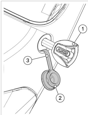
Using the Key
This illustration shows a key (1) inserted in the battery lock mechanism located on the right side of the bike at the bottom of the battery door.
To access the key hole, use your finger to lift the tethered key cap out of the frame hole.
A key is used to secure the battery lock mechanism.
The drive system may be activated by this same key. Please consult the drive system owner/operator manuals to determine.
Please record the key serial number for future use and key replacement.
If your keys are ever lost or stolen, or you would like additional spares, please contact the key manufacturer indicated in the "Frame Specifications" in this manual.

- Main Key
- Spare Key
a. Serial Number
NOTICE
Don't ride with key in battery lock.
Always remove the key from the lock after using it. Keys may be stolen or break off accidentally in the lock. Keep your spare key in a safe place.
TECHNICAL INFORMATION
Specifications
| Item | Specification |
| Drive System | Bosch Performance Line CX |
| Battery | Bosch PowerTube 500Wh |
| Drive-Assist Owner's Manual | https://www.bosch-ebike.com/ |
| Head Tube | UPR: 1-1/8in LWR: 1-1/2in |
| Headset | Integrated, 1-1/8in-1-1/2in |
| Bottom Bracket: Type/Width | Bosch Drive unit |
| Front Derailleur | Braze-on |
| Seat Post: Dia./Binder | 27.2mm/Internal Wedge |
| Min. Seat Post Insert | 80mm |
| Max. Seat Post Insert | Size-specific, SM: 170mm, MD: 185mm, LG:205mm XL:215mm |
| Tire Size x Max. Tire Width | 650b x 47mm (treadless, measured) 700c x 37mm (measured) |
| Maximum. Fork Length | 405mm |
| Brakes: Mount Type / Min./Max. Rotor Dia. | Rigid Fork FR: Flat Mount+20mm / 160/180mm RR: Flat Mount / 160/180mm |
| Axles: Type/Length | RR: Syntace 148×12mm, 168mm length FR: Maxle 110×12mm, 135mm length |
| Intended Use | ASTM CONDITION 2: General Purpose Riding |
| Max. Weight Limit: Total (Rider+All Equipment) | 305lbs / 138kg |
Dimensions = centimeter/inches
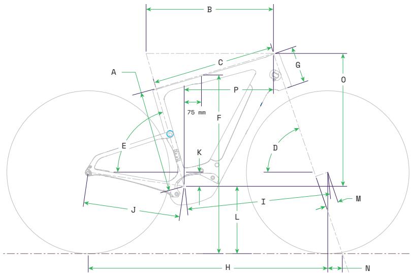
Geometry
| Item | Size | S | M | L | XL |
| A | Seat Tube Length | 41.0 | 44.0 | 50.0 | 55.0 |
| B | Top Tube Horizontal | 53.4 | 55.2 | 56.9 | 58.6 |
| C | Top Tube Actual | N/A | N/A | N/A | N/A |
| D | Head Tube Angle (degrees) | 71.0 | 71.0 | 71.0 | 71.0 |
| E | Seat Tube Angle Effective (degrees) | 74.0 | 74.0 | 74.0 | 74.0 |
| F | Standover | 73.3 | 77.3 | 82.4 | 86.8 |
| G | Head Tube Length | 12.7 | 15.8 | 19.5 | 22.9 |
| H | Wheelbase | 101.8 | 103.8 | 105.7 | 107.6 |
| I | Front Center | 60.6 | 62.5 | 64.4 | 66.3 |
| J | Chain Stay Length | 42.0 | 42.0 | 42.0 | 42.0 |
| K | Bottom Bracket Drop | 6.4 | 6.1 | 6.1 | 5.9 |
| L | Bottom Bracket Height | 28.9 | 29.2 | 29.2 | 29.4 |
| M | Fork Rake | 5.5 | 5.5 | 5.5 | 5.5 |
| N | Trail | 6.3 | 6.3 | 6.3 | 6.3 |
| O | Stack | 54.9 | 57.5 | 61.0 | 64.0 |
| P | Reach | 37.7 | 38.7 | 39.4 | 40.2 |
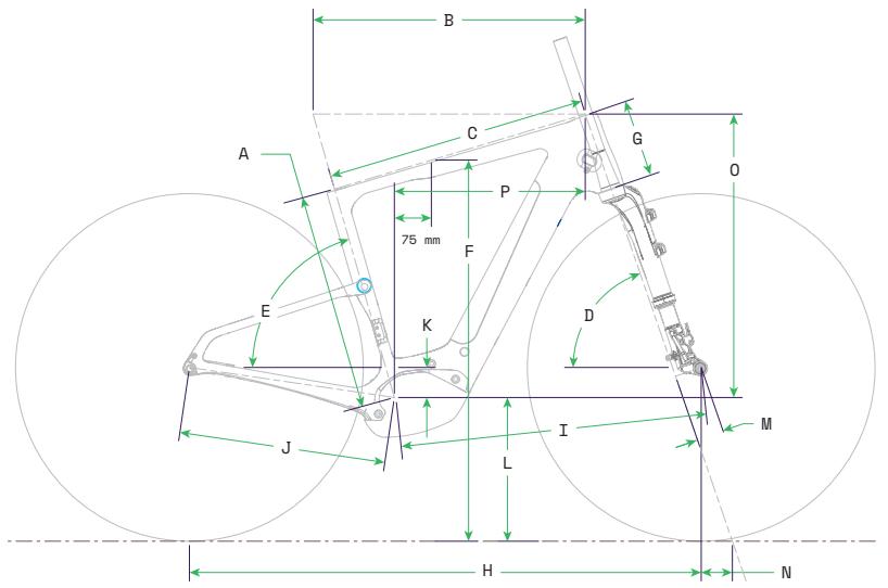
Geometry - w/Lefty Oliver
Dimensions = centimeter/inches
| Item | Size | S | M | L | XL |
| A | Seat Tube Length | 41.0 | 44.0 | 50.0 | 55.0 |
| B | Top Tube Horizontal | 53.4 | 55.2 | 56.9 | 58.6 |
| C | Top Tube Actual | N/A | N/A | N/A | N/A |
| D | Head Tube Angle (degrees) | 71.0 | 71.0 | 71.0 | 71.0 |
| E | Seat Tube Angle Effective (degrees) | 74.0 | 74.0 | 74.0 | 74.0 |
| F | Standover | 73.3 | 76.3 | 81.4 | 85.8 |
| G | Head Tube Length | 12.7 | 15.8 | 19.5 | 22.9 |
| H | Wheelbase | 101.8 | 103.8 | 105.7 | 107.6 |
| I | Front Center | 60.6 | 62.5 | 64.4 | 66.3 |
| J | Chain Stay Length | 42.0 | 42.0 | 42.0 | 42.0 |
| K | Bottom Bracket Drop | 6.4 | 6.1 | 6.1 | 5.9 |
| L | Bottom Bracket Height | 27.9 | 28.2 | 28.2 | 28.4 |
| M | Fork Rake | 5.5 | 5.5 | 5.5 | 5.5 |
| N | Trail | 6.0 | 6.0 | 6.0 | 6.0 |
| O | Stack | 54.9 | 57.5 | 61.0 | 64.0 |
| P | Reach | 37.7 | 38.7 | 39.4 | 40.2 |
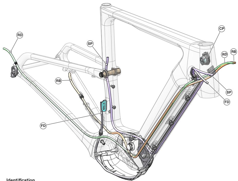
Cable Routing Overview
Identification
RB - Rear Brake Line
Do not attempt to work on the cable routing yourself. Due to the complex nature of the parts and the level of disassembly required to gain access, have any repairs or replacements of the battery, cables or hoses parts identified performed by an authorized Cannondale e-bike service center.
Powertube Battery
The drive system battery (2) is housed within the bicycle downturn.
The battery can be charged via the charge port (9) or removed for charging.
To remove the battery:
- Secure the bike upright to prevent it from falling over.
- Make sure the bike drive system is OFF.
- Lift out the key cover from the frame; insert the key (5) into the key slot (8).
Turn the key clockwise to permit the release of the battery.
Use your hand to lift the battery handle feature (9) at the bottom edge of the battery cover out slightly.
- Press in on the battery release tab (7) located on the lower part of the battery.
Once pressed, the battery will be allowed to slide out from the lower battery mount.
To install the battery:
- Secure the bike upright to prevent it from falling over.
-
Insert the upper battery so that the battery socket engages with the upper frame connector (4).
-
Press in on the lower part of the battery and turn the key clockwise to lower the latch.
Turn the key counter-clockwise to re-engage the lower locking mechanism (6). - Remove the key.
NOTICE
Do not ride the bike without the battery cover installed. Dirt, water and other contaminants can enter frame and/or damage the battery.

WARNING
Periodically, check to make sure the battery is securely mounted inside the frame.
Check the battery after any fall or impact. Check for loose or damaged parts.
Use only the specified battery. Do not modify the battery or other parts.
If you take the battery out, replace and secure the battery cover on the frame.
If damage is found; do not ride the bike. Have any damaged part replaced with a new one. Contact your Cannondale Dealer.
Do not tamper/battery-to-cover attachment only
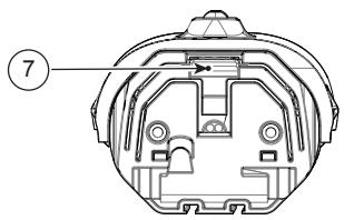
Bottom view
Battery Charging Port
The battery charging port is located on the left side of the bicycle at the headtube. The charging port enables the battery to be charged while installed in the bicycle.

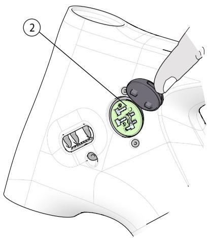
To connect to the charger cable to the port connector:
- Place the bike and charger in a secure area where both will remain undisturbed while the battery is charging.
- Lift up the battery port cover (1).
- Attach the specified charging cable to the charge socket (2).
- When charged, disconnect charger cable from the charge socket and replace cover. Make sure cover is seated fully into the frame opening.
- Disconnect the charger from its source of power.

WARNING
Follow the drive system manufacturer's instructions for charging and handling the battery.
Incorrect charging or handling can result in a fire, an explosion resulting serious injury or death.
Do not insert anything other than the specified charging connector into the charging socket.
- RD Mount
-
Screw
-
Wireless
- Di2 Plug
The front derailleur mount is a removable "braze-on type."
When using a mechanical FD system or SRAM Etap, make sure the frame plug is installed to prevent the intrusion of water or debris into the frame.
When using Di2 Systems, use the Di2 Cable Plug.
To replace:
Remove the rear wheel.
Remove the mounting screw(s) and remove the old hanger from the dropout.
Clean the area around the dropout and inspect the frame carefully for any cracks or damage. If you find damage have the frame inspected by your Cannondale Dealer .
If the dropout is not damaged, apply a light film of grease between the frame and mount. This will help minimize any noise or "creaking" that might result from very slight movement between the dropout and mount during movement of the derailleur.
Slide the new hanger onto the dropout.
Clean and apply Loctite® 242 (or medium strength thread lock) to the screw threads and tighten to the specified torque.
Rear Fender Support
Identification
-
Fender Support
-
Screw (2X)
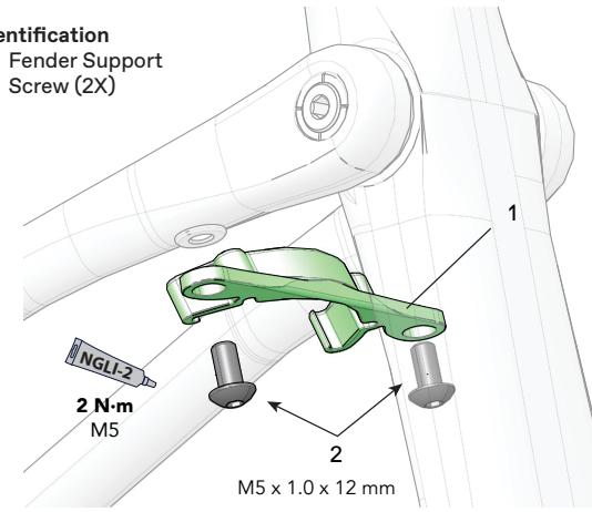
Maintain tire clearance with fender.
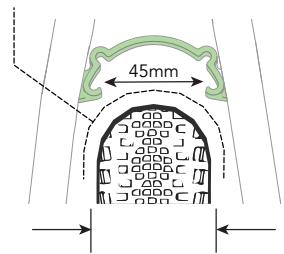
The wheel rim and tire models, and fender shape used will affect the fender clearance.
Please Note:
(1) Check tire clearance with the tire fully inflated. (2) Mounting a tire with a smaller profile, one smaller than the maximum tire size for the frame, or currently on the wheel may be required to fit a compatible fender. (3) Any fender must be secured by the support and should not be loose. (4) Do not modify any parts or the frame in order to install a fender.
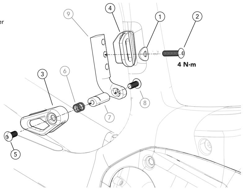
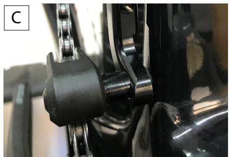
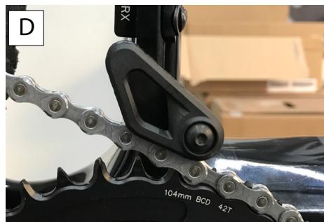
Chain Guide
The chain guide is an important chain retention device that must be used in single chainring applications (no FD mounted).
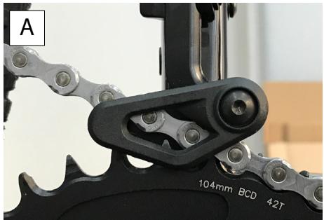
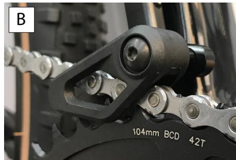
Install the chain guide assembly onto the FD mount (4) using the curved washer (1) and the M5 bolt (2) using a torque wrench. Position the guide shroud (3) vertically so it covers the chainring teeth, with clearance between the guide and the chain, as shown in next figure A and B.
Adjust the guide shroud bolt (4) to align it so that the chain does not rub against it when on the smallest or largest gear of the rear cassette. See next figure C.
The chain guide has an "open" position (see D) that can be used to remove the chainring without having to disassemble the guide itself.
WARNING
Failure to install and maintain the guide can result in a moving chain from coming off. Replace the guide if it is worn, missing or damaged.
Identification
- Curve washer
- M5 Bolt
- Shroud
- FD Mount
- Bolt
- Spring
- Stud
- Bolt
- Arm
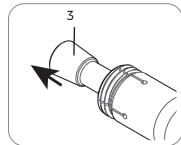
LockR Pivot
To remove the LockR from the frame:
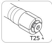
- Loosen the screw 4-6 turns using a T25 Torx key.
- Tap head of screw with a rubber mallet to un-seat the wedge bolt located on the opposite side.
- Remove the screw and wedge bolt from the still-installed axle.
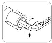
- If the wedge did not come out with the screw, insert a 5 mm hex key and turn to free and remove it. If wedge still sticks insert a wooden or plastic dowel into the drive side and drive it out.
- To remove the axle itself, insert a 6 mm hex key into the axle on the non-drive side and turn counter-clockwise until it can be removed.
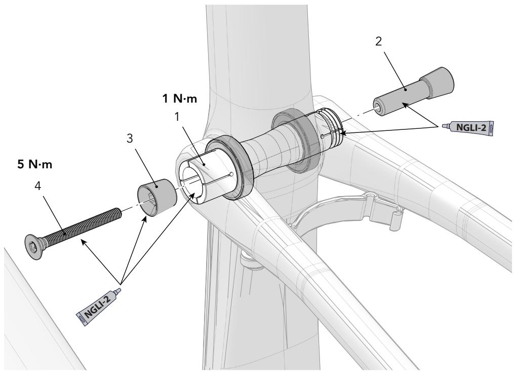
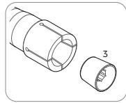
To install the LockR on the frame:
- Disassemble and clean all parts of the LockR axle. Do not install it assembled.
Inspect the parts for damage (burrs, scratches, deformity, wear). Replace the entire LockR assembly if any damage is found. - Apply a light coating of a high-quality bicycle bearing grease to all parts.
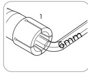
- Align the linkage and bearing and insert the threaded end of the pivot axle (1) in from the non-drive side.
- Tighten the inserted pivot axle to 1 N·m using a 6 mm hex key fitted torque wrench from the non-drive side.
- Insert the wedge bolt (2) into the drive side of the axle and insert the small end of the wedge (3) into the non-drive side axle head.
- Thread the screw (4) into wedge bolt with a wrench and tighten to 5.0N· m .
NOTICE
Use a calibrated torque wrench. Exceeding 1 N·m will result in permanent damage to the LockR pivot system.

- Do not install assembled.
Apply grease to all parts.
Unthread & tap mallet
dislodge & remove
Insert 5mm & turn to free
Remove
Unthread Remove
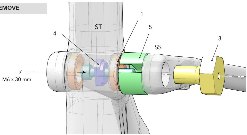
Seat Tube / Seat Stay Pivot Bearings
REMOVE
- Remove LockR pivot hardware.
- Insert remove plate (4) through ST pivot so its small OD cylindrical surface engages the inside of the bearing.
- Insert M5X30mm screw (7) through hole in remove plate (4) so threads are pointing out through SS pivot end.
-
Thread tool handle (3) onto M6X30mm screw (7) only 2-3 turns.
-
Pull SS end away from ST just enough to allow remove cup (5) to be snapped over M6X30mm screw (7).
- Hold M6X30mm screw (7) stationary with 5mm hex key while turning tool handle (3) until bearing is fully pulled out of pivot and into remove cup.
- Unthread tool handle to remove tool from the frame.
- Repeat for the other side.
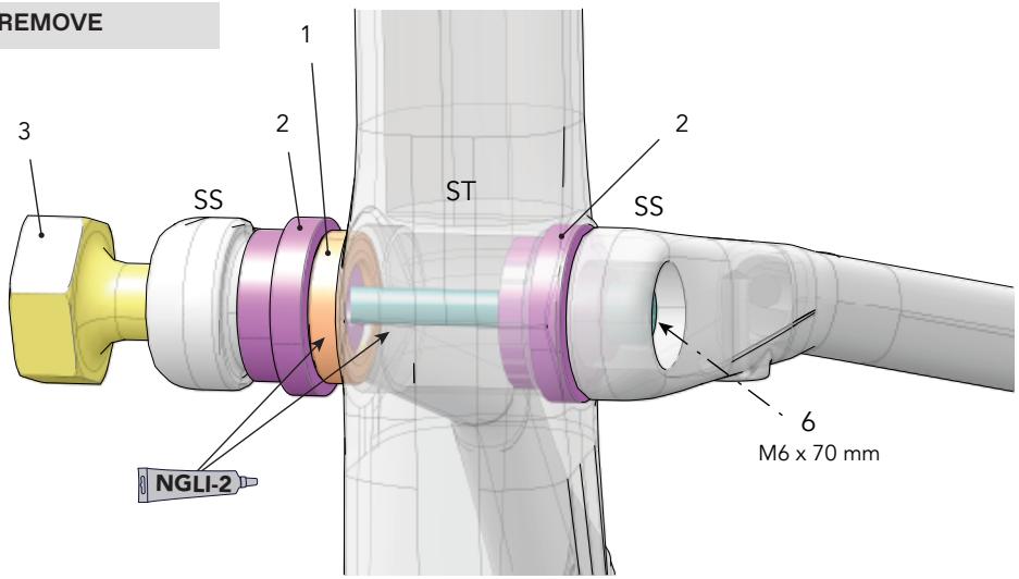
INSTALL
- Pull drive side SS end away from ST just enough to slip larger OD side of install plate (2) into ST pivot bore.
- Place new bearing on smaller OD side of 2nd install plate (2).
- Apply grease to non-drive side ST pivot bore.
- Pull non-drive side SS end away from ST just enough to slip 2nd install plate (2) and bearing into position.
- Insert M6X70mm screw (6) through both install plates so it's threaded end protrudes through SS end on non-drive side.
-
Thread tool handle (3) onto M6X70mm screw (6) and tighten while holding screw stationary with 5mm hex key. Tighten until bearing is fully pressed into ST pivot bore.
-
Remove Tool handle (3), M6X70 screw (6) and drive side install plate (2).
- Place new bearing on smaller OD side of install plate (2).
- Apply grease to drive side ST pivot bore
- Pull drive side SS end away from ST just enough to slip install plate (2) and bearing into position.
- Insert M6X70mm screw (6) through both install plates so it's threaded end protrudes through SS end on drive side.
- Thread tool handle (3) onto M6X70mm screw (6) and tighten while holding screw stationary with 5mm hex key. Tighten until bearing is fully pressed into ST pivot bore.
- Unthread tool handle (3) and remove all tools from pivot.
- Continue with LockR axle installation procedure.
REMOVE
REMOVE
Identification
- Bearing
- Install Plate
- Tool Handle
-
Remove Plate
-
Remove Cup
- Screw M6 × 70mm
- Screw M6 × 30 mm
ST Seat Tube
SS Seat Stay End
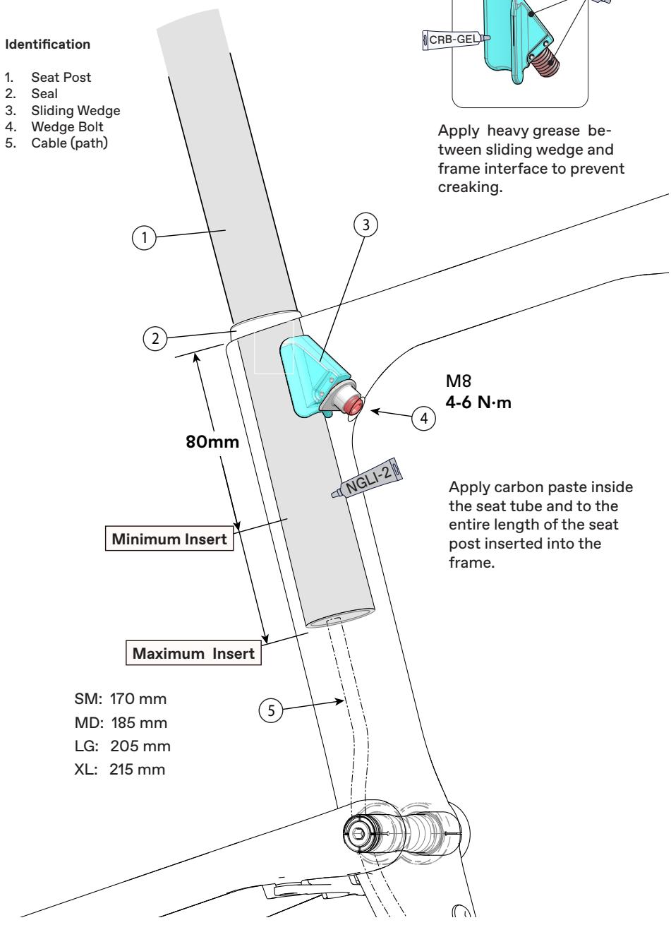
Seat Post
Installation & Adjustment
Before installing:
Use a clean shop towel to wipe out any residual carbon gel paste from the inside the seat tube.
- Apply fresh carbon friction gel to the seat post and place a little bit inside the seat tube.
Make sure the seal is in good condition and in place on the seat post.
To adjust:
- Insert the prepared seat post into the frame. Maintain the specified minimum insert.
- Set the saddle height.
- Insert 4mm hex through the underside seat tube opening as shown.
- Tighten the binder screw to the specified torque.
- Slide the seal against the frame.
NOTICE
- Do not use any spray cleaners or solvents to clean. Use only a clen dry shop towel.
- Do not exceed the specified torque. If you over-tighten the binder bolt, you will damage the binder, seat post or the frame.
Maintenance
Periodically, remove the seat post and the clamp assembly to clean, inspect for damage and renew the application of grease and carbon gel.
See also, "Seat Binder Inspection."
Minimum Insert
The minimum insert depth the seat post must be inserted into the frame is 65mm.
Maximum Insert
The total length of seat post that may be inserted will vary with the frame size and should be checked in each frame.
To check, carefully slide a seat post into the frame until it stops; then lift it up 5mm.
NOTICE
A seat post should not be bottomed out inside the frame at any time. Have your Cannondale Dealer size the seat post appropriately.

WARNING
THE SEAT POST MUST ONLY BE CUT BY A PROFESSIONAL BIKE MECHANIC. Incorrectly cutting the seat post can result in damage leading to an accident.
For more information about carbon fiber seat posts, see also "Care and Maintenance of Carbon Fiber Seat Posts" in your Cannondale Bicycle Owner's Manual.
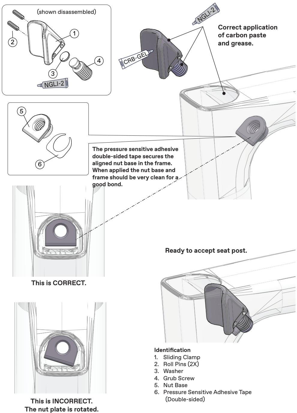
Seat Binder Inspection
The internal seat binder system consists of a sliding clamp assembly and a nut base with a double-side adhesive holding it to a special mating surface inside the seat tube. The sliding clamp parts can be removed when the seat post is out.
Always clean the surfaces of the sliding clamp by wiping them with a clean dry lint-free shop towel only. Do not soak the parts, as the internal washer is lubricated with grease. Solvents will wash out the lubricant and the assembly will have to be regreased by disassembling it completely.
NOTICE
If the nut base has become rotated, it should be removed and re-affixed to the frame. The process is described in the Service Instruction for the parts kit. These instructions are not provided in this manual. We recommend that you have a Cannondale Dealer perform the replacement.
Please Note: During first assembly of the nut base, it is important to not push on the 4mm allen when tightening onto the seatpost. This can disengage the adhesive tape before proper bonding. A poor bond can lead to misalignment. The 3M^TM VHB™ Tape 5980 is pressure sensitive.
To inspect
- To remove the seat post. See previous page.
- To remove the sliding clamp, use a 4 mm hex key and turn grub screw slowly clockwise until the clamp is disengaged from the nut base.
- Use the 4mm hex to push the clamp out through the seat tube opening.
- Look into the frame opening. Use a pen flashlight. Check the position of the nut base. See CORRECT next page.
-
If the nut base is missing, or rotated or damaged, a replacement is required. This service should be performed by a Cannondale Dealer.
-
Check the condition of the clamp. The seat post face and frame contact surfaces should be smooth. If they are not, the clamp assembly should be replaced with a new one.
- Clean the parts and inside the seat tube with a dry shop towel and re-apply grease and carbon paste as indicated.
- Returning the sliding clamp to the frame, using the 4 mm hex to guide it to the nut base.
9 Turn the grub screw counter-clockwise to engage the nut base. Make sure it is engaged sufficiently to easily insert the seat post into the seat tube.
REPLACEMENT PARTS
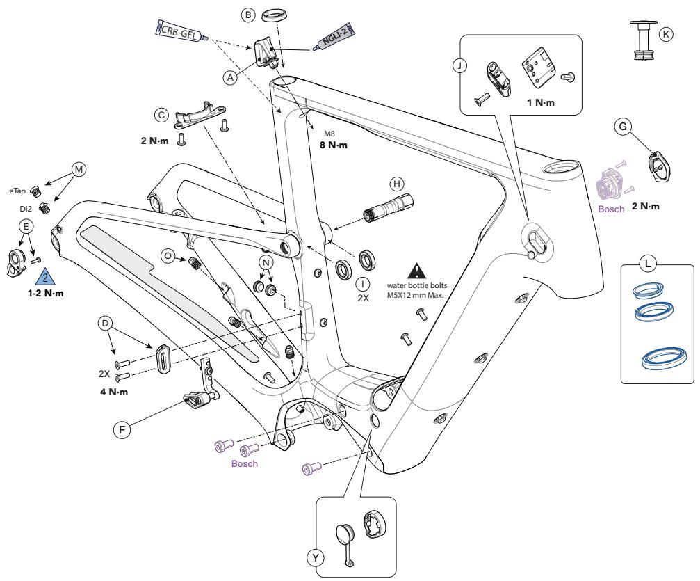
Frame
| ID | Part Number | Description |
| A | K26001 | Seat Binder |
| B | K26011 | Seatpost Grommet Round 27.2 |
| C | K11000 | Rear Fender Mount |
| D | K33041 | FD Mount |
| E | K33049 | Derailleur Hanger TA ST SS 073 |
| F | K11141 | Chainguide |
| G | K34159 | Charge Port Cover V2 |
| H | K91000 | LockR Pivot Hardware 65mm |
| I | K36087 | Pivot Bearing 6802 x2 |
| J | K32250 | Modular Cable Guides 4-5-5 Qty 2 |
| ID | Part Number | Description |
| K | K35009 | SL Compression Plug w/ Top Cap |
| L | K35010 | 1-1/8-1.5 Int Hdset w/ 36 Deg CR 25/5 TC |
| -- | K91010 | Kingpin Bearing Tool |
| -- | K83011 | Maxle TA Bolt, 110×12 135mm |
| M | K32280 | Di2 & Wireless Plugs 5.5mm |
| N | K32340 | FD Grommets Open & Closed 7.5mm |
| O | KP449/ | Rubber Brake Housing Grommets |
P
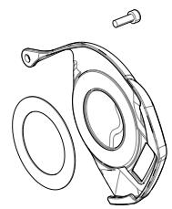
Heat Shield
Q
Motor Covers
LFT
Battery Cover
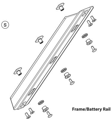
Frame/Battery Rail
Battery / Motor Covers
| ID | Part Number | Description |
| P | K34060 | NDS Adhesive Motor Cover |
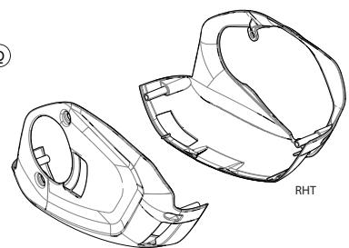
| R | K3420930 | Battery Cover DT Top Exit BPL |
| K3420970 | Battery Cover DT Top Exit CHP | |
| K3420980 | Battery Cover DT Top Exit GRY | |
| K3420990 | Battery Cover DT Top Exit EMR |
| ID | Part Number | Description |
| Q | K3415110 | Motor Cover BPL |
| K3415120 | Motor Cover CHP | |
| K3415130 | Motor Cover GRY | |
| K3415140 | Motor Cover EMR | |
| S | K34141 | Battery Rail Mounting Kit |
E-BIKE MAINTENANCE
Before and After Each Ride:
- Clean and visually inspect the entire bike for cracks or damage. See "Inspect for Safety" in your Cannondale Bicycle Owner's Manual."
- Make sure the battery is fully charged and mounted securely. Follow the drive system charging instructions. Battery charge discharge capacity will decline with usage. Have older battery replaced when it is fails to charge within the time indicated, and/or to provide power reliably.
- Test the drive-assist system, make sure the drive system functions normally.
- If your E-Bike model was equipped a lighting system, brake lights, headlights, tailights and number plate illumination, make sure these lights are each functioning normally. Make sure the number plate is clean and readable.
- Check the front and rear brake conditions, make sure they function normally.
- Check tire pressure and wheel conditions. Check tire pressure and the condition of the wheels. Ensure the tires are not damaged and do not have excessive wear. Ensure there are no broken or missing wheel parts and that the wheels are firmly attached via secured skewers/axles.
- Confirm the drive chain condition is in good condition, is clean and well-lubricated. Chain wear is greater compared with pedal only bikes. This requires frequent inspection and replacement. Ensure the gears operate normally through the entire range.
- Check the bicycle brakes. Make sure they are working well. Brake system pad and disc wear is greater compared with pedal only bikes. This requires frequent inspection and replacement.
- Inspect condition of electrical cables (i.e. Kinks free, no signs of abrasive wear). Check cable at dropout end when assembled properly will prevent cable from contacting brake rotor.
Maintaining Your Bike
- Read your Cannondale Bicycle Owner's Manual for information on an owner's reposnibility for the routine/ basic inspection and maintenance of your bike.
Consult with your Authorized Cannonda- le Dealer to create a complete maintenance program for your riding style, components, and conditions of use.
Follow the maintenance recommendations given by the component manufacturer's for the various parts of your bike.
- Recommended after the first 150km bring your bike to your Authorized Cannondale Dealer for an initial check-up. It should include checks of the drive-assist system, drive chain condition, proper shifting, accessories, wheels and tire condition, brakes, etc. This visit will help you establish a schedule for repeated visits appropriate for how and where you ride.
- Every 1000 km, bring your bike in to your Authorized Cannondale Dealer for a regular detailed inspection, adjustment, and replacement of wear items across the entire bike. Electrically powered-assist cycle (electric bikes) can wear out wheels, tires, drive chain, brakes, more quickly.
Maintaining Your Bike's Drive System
NOTICE
Drive-assist system components must only be serviced at an authorized service center. This will ensure the quality and safety of the drive-assist system.
Never attempt to open, remove drive system parts from the frame, or work on them yourself. Other components of the electric bicycle drive (e.g. drive chain, front chain ring, rear cassette, rear derailleur, crank arm) must be serviced by an Authorized Cannondale Dealer.
Replacement parts must be identical to the original Cannondale specification for the bike. Failure to replace components with original specification can result in serious overload or other damage to the drive unit.
Unauthorized opening or service of the drive unit will void the warranty.
WARNING
Perform a pre-ride-check before and after each ride. Frequent checks are necessary to identify and correct problems that can lead to an accident. Do not ride your bike if it does not operate normally or has broken, damaged, or missing parts. Have any damage inspected and repaired by your Cannondale Dealer before riding again.
You can be severely injured, paralyzed or killed in an accident if you ignore this warning.
Cleaning
When cleaning your bike, use a damp sponge or a soft brush with only a mild soap and water solution. Rinse the sponge often. Do not spray water directly on controls or drive system components.
NOTICE
Do not use a pressure washer or dry with compressed air. This will force contaminants into sealed areas, electrical connections/components promoting corrosion, immediately damaging, or result in accelerated wear.

WARNING
Keep water away from the electrical components.
Make sure the bike is secured upright and can not fall over accidentally while you are cleaning it.
Don't rely on the kickstand. Use a sturdy portable bicycle wheel stand to hold the bike upright.