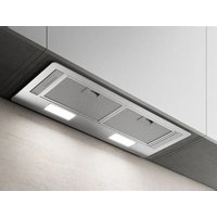
LULLABY - Range hood ELICA - Free user manual and instructions
Find the device manual for free LULLABY ELICA in PDF.

User questions about LULLABY ELICA
0 question about this device. Answer the ones you know or ask your own.
Ask a new question about this device
Download the instructions for your Range hood in PDF format for free! Find your manual LULLABY - ELICA and take your electronic device back in hand. On this page are published all the documents necessary for the use of your device. LULLABY by ELICA.
USER MANUAL LULLABY ELICA
EN Instruction on mounting and use
natural_image
Two identical black human figures side by side, no text or symbols present.
natural_image
Illustration of two hands in different colors (white and gray) with no text or symbols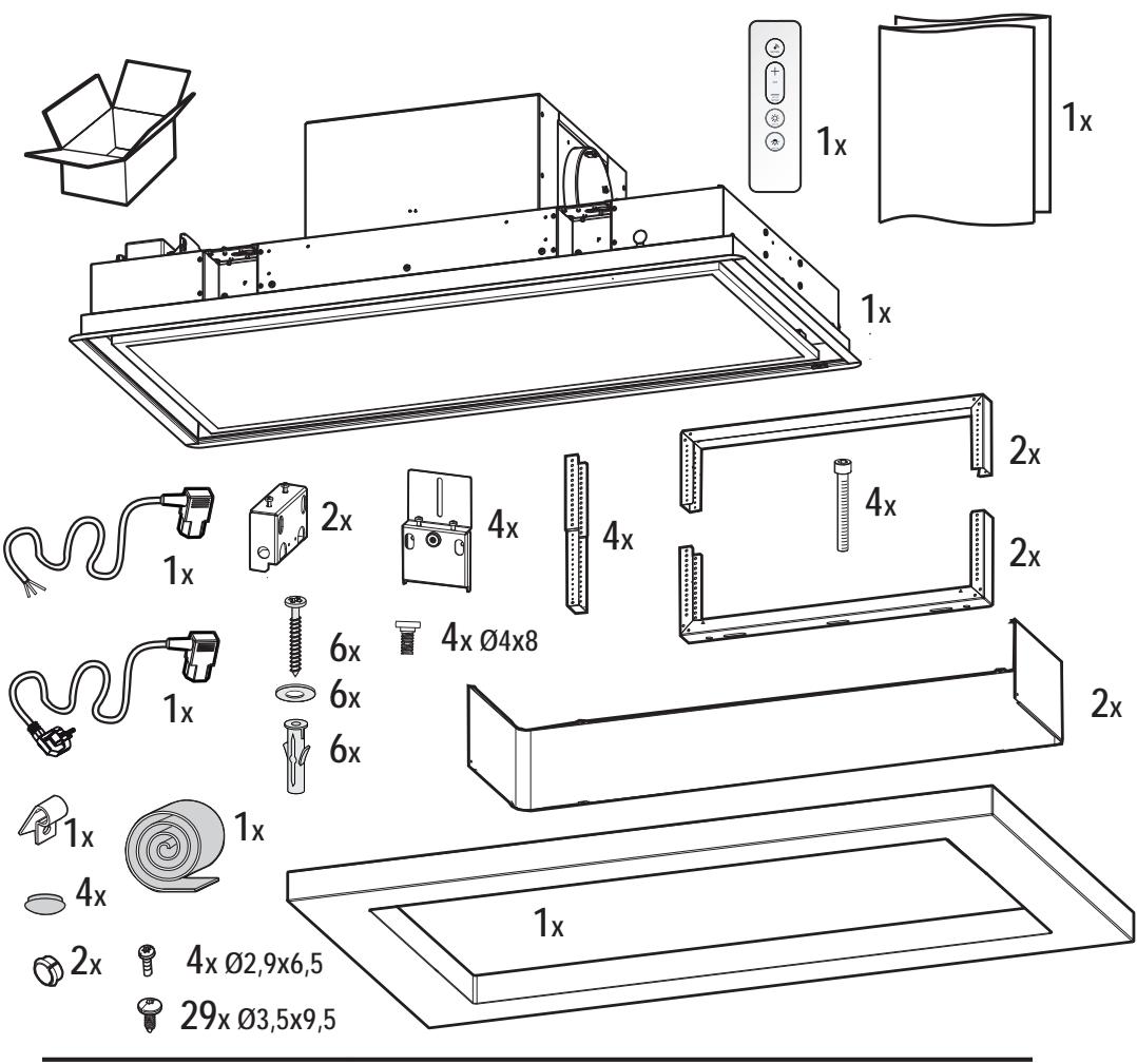
text_image
1x 1x 1x 2x 4x 4x 4x Ø4x8 2x 2x 6x 6x 6x 1x 1x 4x 2x 4x Ø2,9x6,5 29x Ø3,5x9,5 1x
natural_image
Technical line drawing of a mechanical assembly with a hanging weight and rectangular plate (no text or symbols)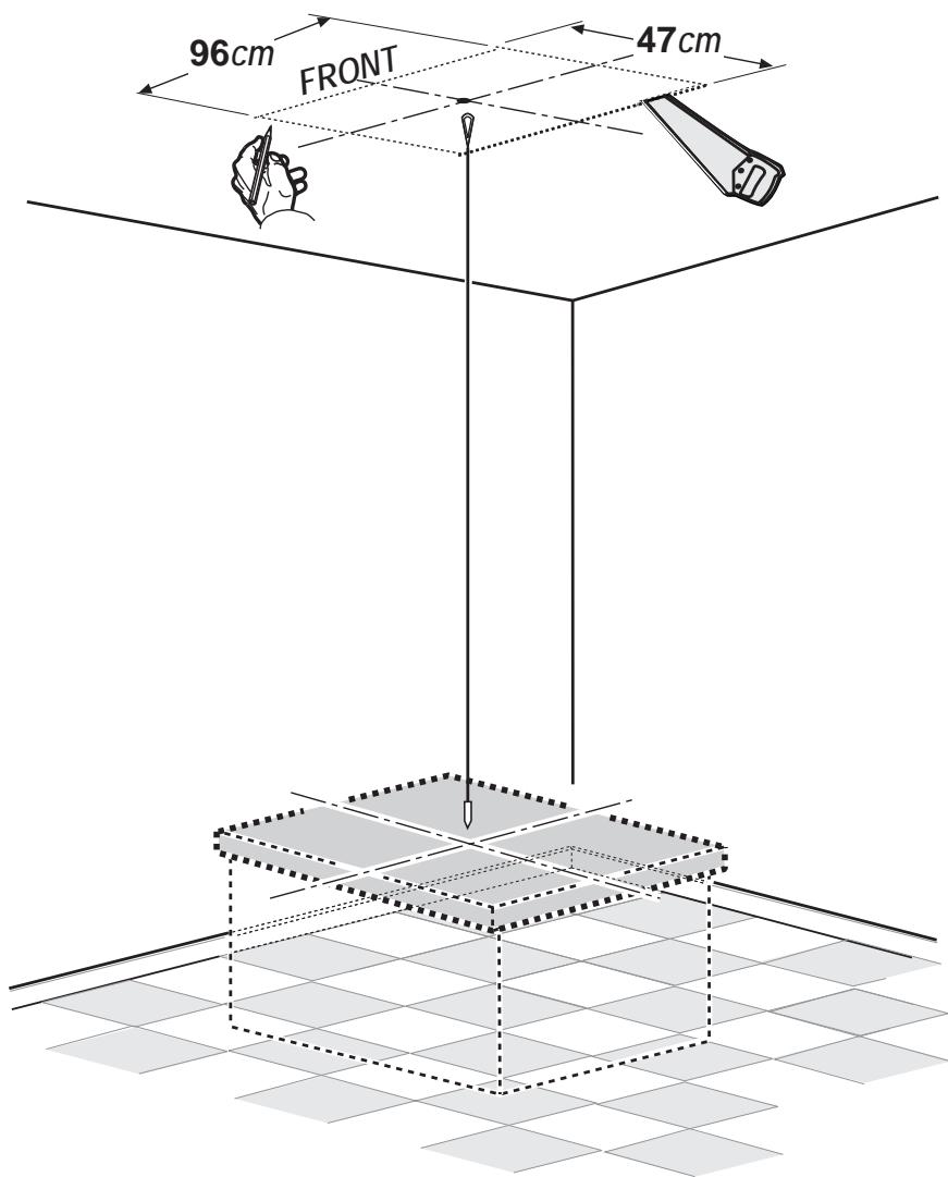
text_image
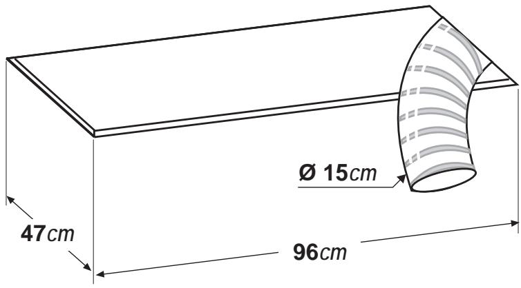
96cm FRONT 47cm2
natural_image
Technical line drawing of a mechanical tool with no visible text or symbols4 x ∅10mm

V \~ Hz

text_image
FRONT 3 5 2 6 1 4
5
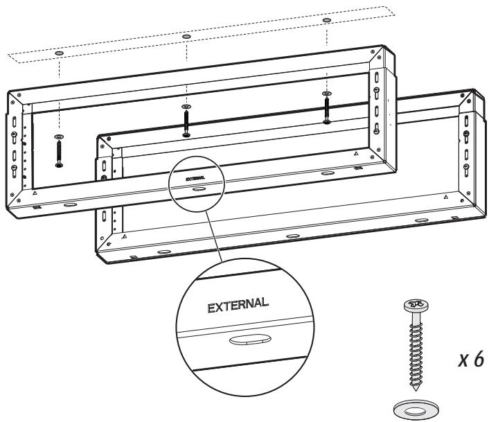
x 6
text_image
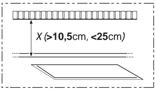
X (>10,5cm, <25cm)
16x ∅3,5x9,5
text_image
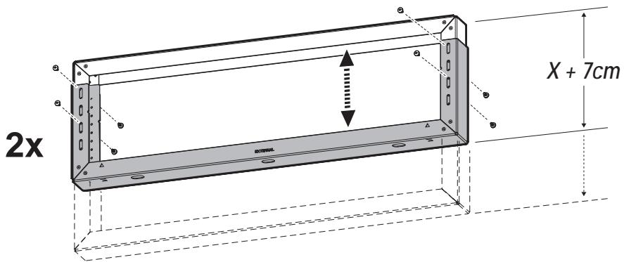
2x X + 7cm6a
text_image
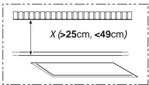
X (>25cm, <49cm)
32x ∅3,5x9,5
natural_image
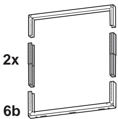
Technical line drawing of a structural frame with labeled dimensions (2x and 6b), no text or symbols present.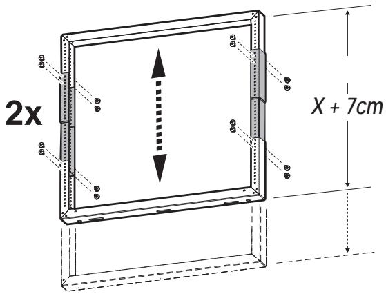
text_image
2x X + 7cm7
text_image
INTERNAL ≥6cm8
text_image
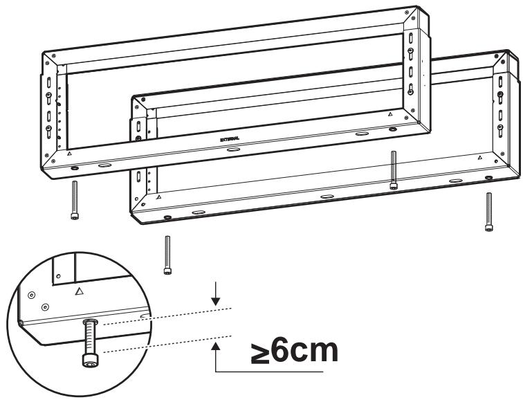
EXTERNAL X 6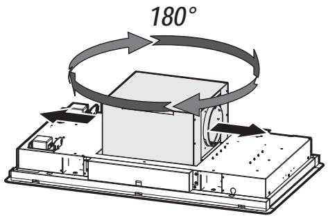
text_image
180°
natural_image
Technical line drawing of a mechanical assembly with directional arrows indicating motion (no text or symbols)
natural_image
Technical line drawing of a rectangular electronic device with mounting base and internal components (no text or symbols)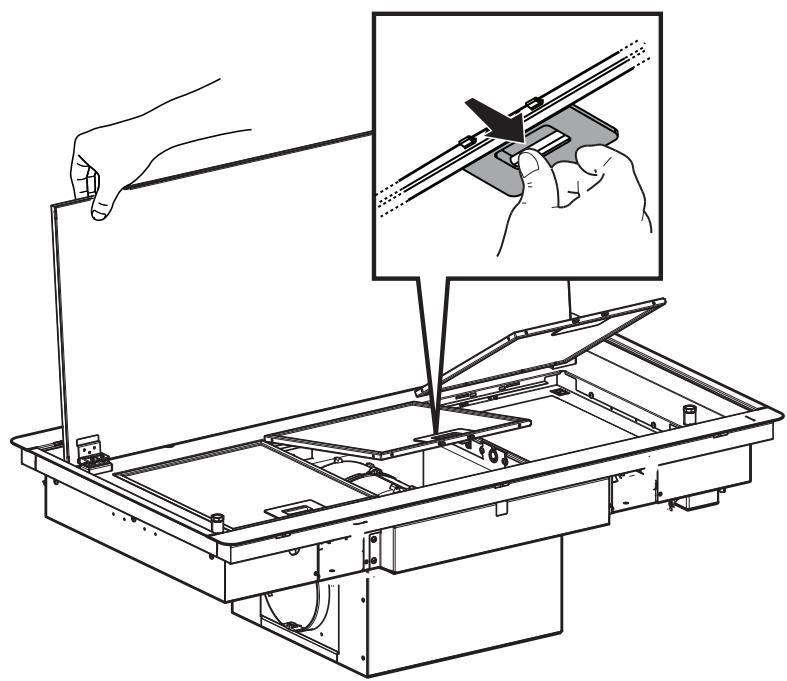
natural_image
Technical line drawing of a mechanical assembly with an inset showing hand positioning and tool insertion (no text or symbols)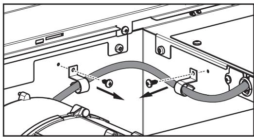
natural_image
Technical diagram of a mechanical assembly with hoses and connectors (no text or labels)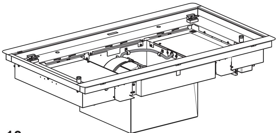
natural_image
Technical line drawing of a mechanical assembly with internal components (no text or symbols)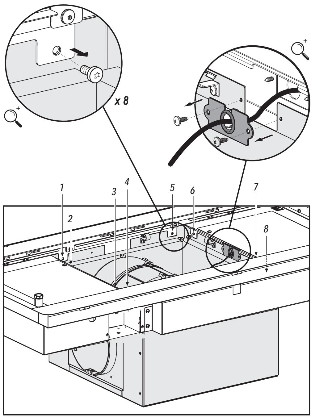
text_image
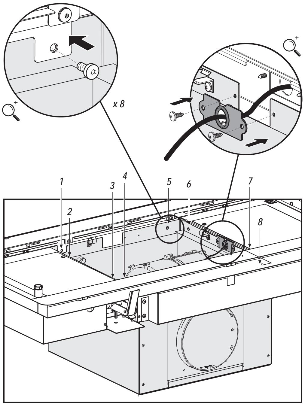
x 8 1 2 3 4 5 6 7 8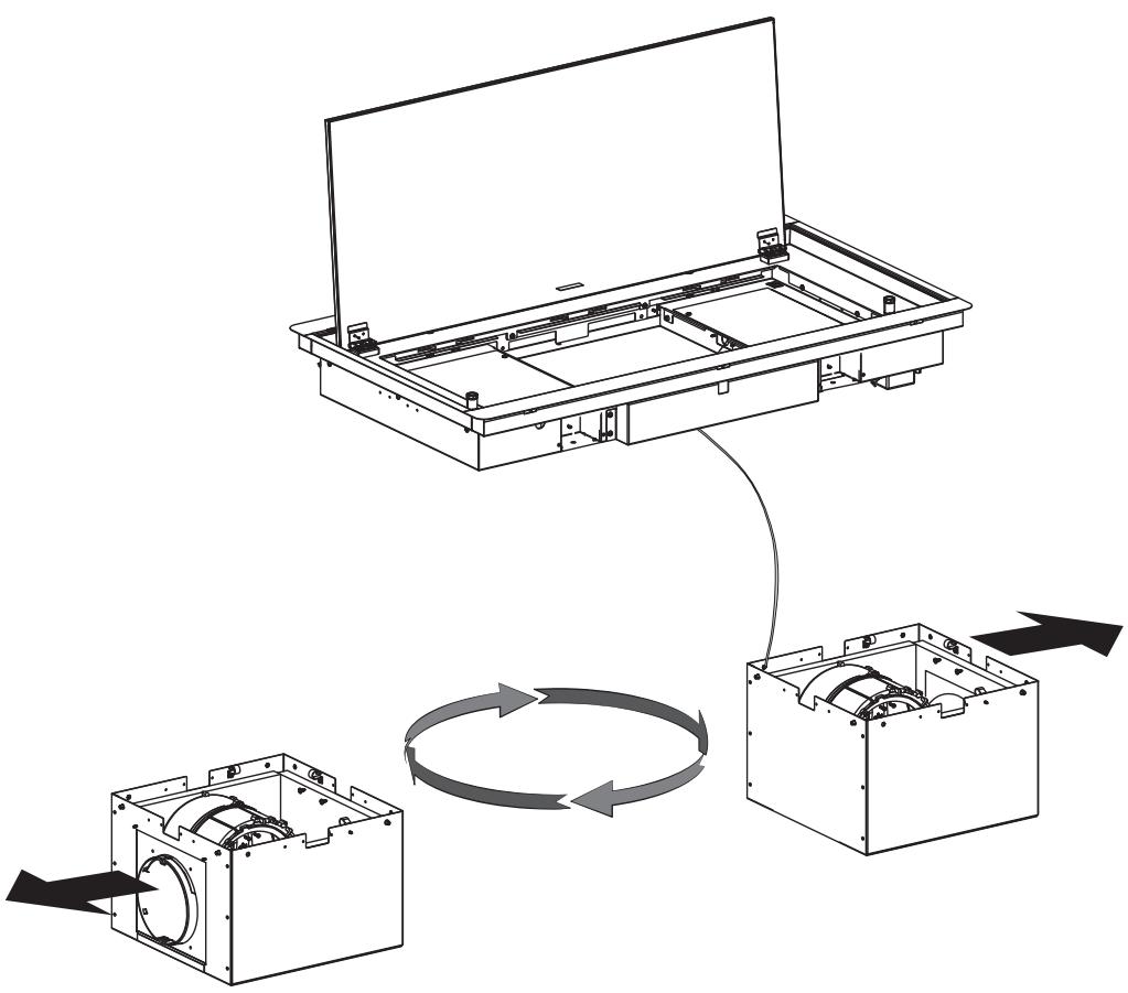
flowchart
graph TD
    A["Initial Component"] --> B["Assembly Unit"]
    B --> C{Rotation}
    C -->|Yes| D["Receiving Component"]
    C -->|No| E["Outstretched Component"]
    D --> F["Final Assembly Unit"]
    E --> F
12
text_image
Technical diagram of a device with numbered components and magnified views showing assembly details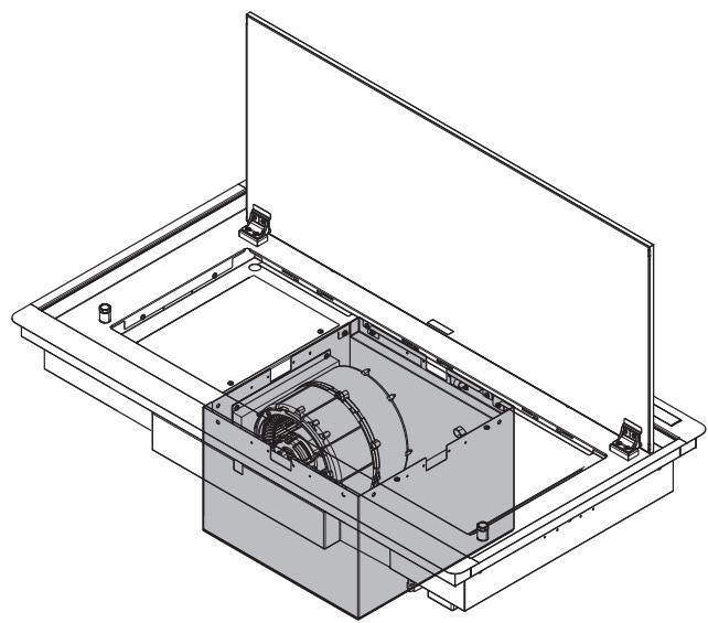
natural_image
Technical line drawing of a mechanical assembly with housing, frame, and internal components (no text or symbols)
natural_image
Isometric technical drawing of a mechanical component with labeled parts (1 and 2), no readable text or symbols beyond labels
natural_image
Technical line drawing of a mechanical housing assembly with an open top view and internal components (no text or symbols)14
natural_image
Technical diagram of a mechanical assembly with hoses and connectors (no text or labels)
natural_image
Technical line drawing of a mechanical assembly with internal components (no text or symbols)
text_image
DOWN 19 DOWN UP UP OK! 17.1 DOWN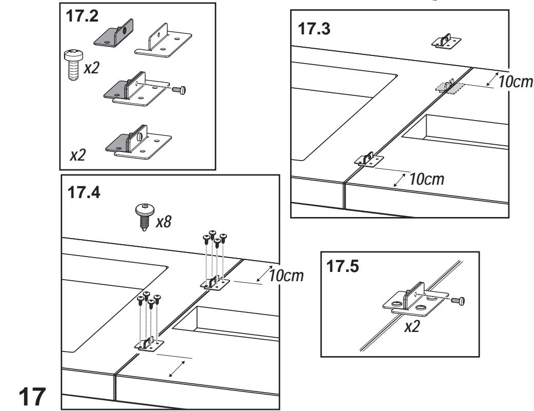
text_image
17.2 x2 x2 17.3 10cm 10cm 17.4 x8 10cm 17.5 x2 17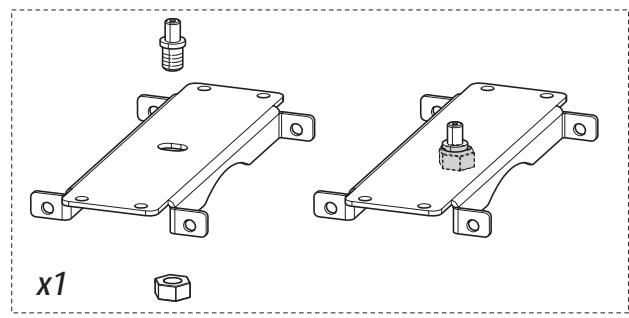
natural_image
Technical line drawing of two mechanical components with bolts and a nut, labeled 'x1' (no text or symbols on the components themselves)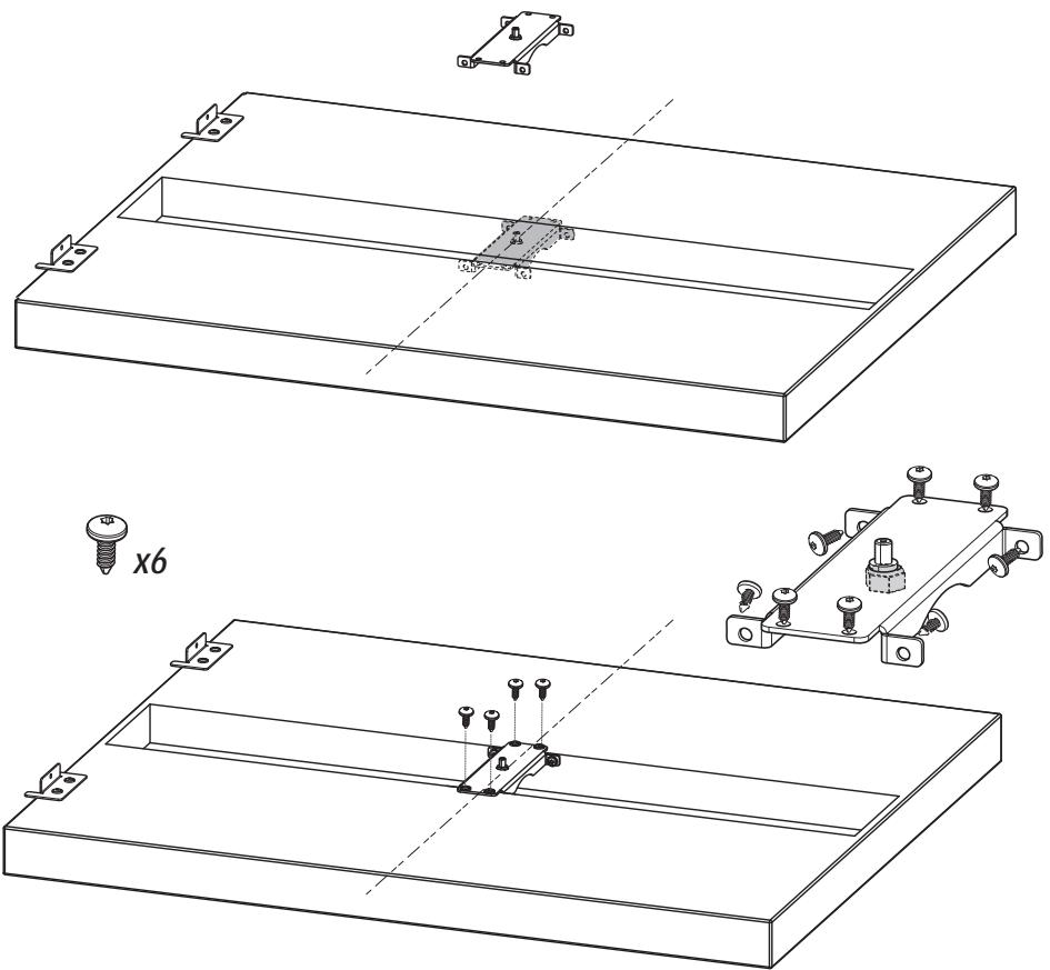
natural_image
Technical line drawing of a mechanical assembly with mounting brackets and mounting holes (no text or symbols)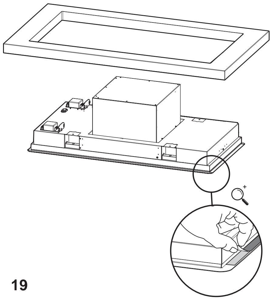
natural_image
Technical line drawing of a mechanical assembly with an inset magnified view showing hand positioning (no text or symbols)

12x ∅3,5x9,5
natural_image
Technical line drawing of a mechanical assembly with mounting brackets and control components (no text or symbols)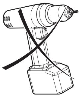
natural_image
Line drawing of a robotic arm with a curved tool inserted, no text or symbols present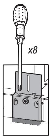
text_image
x8
natural_image
Technical diagram showing a mechanical component with a probe inserted into a housing, labeled 'x4' (no text or symbols on the diagram itself)
1x ∅3,5x9,5
natural_image
Technical line drawing showing three sequential views of a mechanical assembly with clamps and tools (no text or symbols)
natural_image
Simple line drawing of a shopping cart and an eraser (no text or symbols)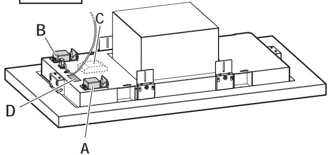
text_image
A B C D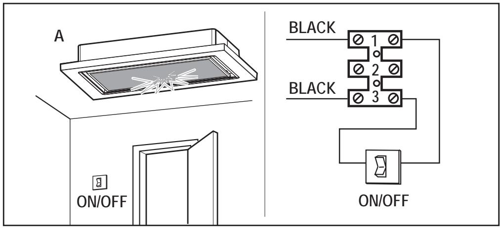
text_image
A ON/OFF BLACK 1 2 3 BLACK ON/OFF

text_image
ON/OFF
text_image
>20W < 100W YELLOW YELLOW GREY ORANGEB+C

text_image
Diagram showing a series of hanging objects with a triangular warning symbol, indicating displacement or safety.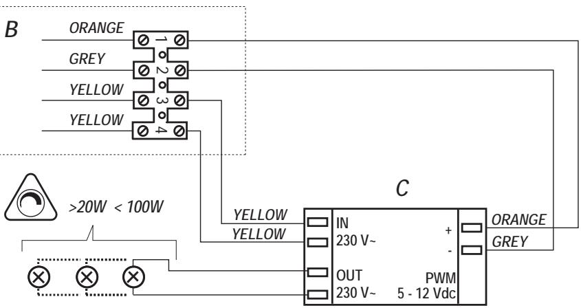
text_image
B ORANGE GREY YELLOW YELLOW >20W < 100W YELLOW YELLOW C IN 230 V~ + - OUT 230 V~ PWM 5 - 12 Vdc ORANGE GREY
D
KIT WINDOW
natural_image
Simple line drawing of a door with sound waves and a speaker icon (no text or symbols)
natural_image
3D white figure holding a red wrench, no text or symbols present
natural_image
Simple line drawing of a computer monitor with an arrow pointing to the screen (no text or symbols)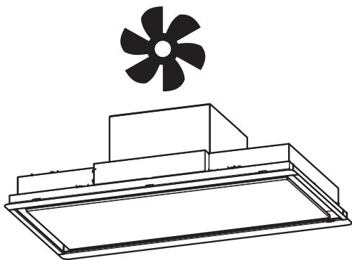
natural_image
Technical line drawing of a fan assembly with a propeller above (no text or symbols)
natural_image
Simple line drawing of a rectangular frame with two horizontal lines inside, mounted on a base (no text or symbols)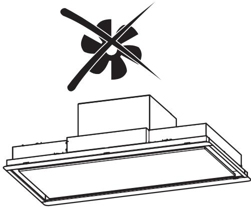
natural_image
Technical line drawing of a mechanical component with a propeller above it (no text or symbols)23.1
text_image
KIT WINDOWKIT WINDOW
text_image
1 2 3 L N N L X Y23.2
text_image
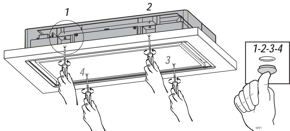
1 2 3 4 1-2-3-426
natural_image
Technical line drawing of a mechanical assembly with internal components and mounting bracket (no text or symbols)27
ON/OFF
text_image
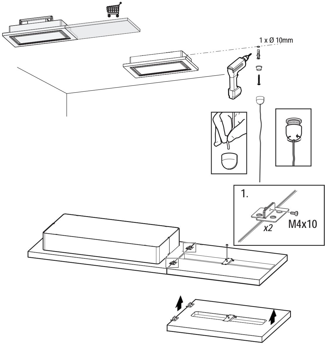
1 x Ø 10mm 1. x2 M4x10
flowchart
graph TD
    A["Lock"] --> B["Rotate"]
    B --> C["Unlock"]
    style A fill:#f9f,stroke:#333
    style C fill:#f9f,stroke:#333
    note right of B
        2.
    end
28
natural_image
Illustration of a hand holding a tool above a mechanical component (no text or symbols)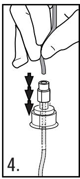
natural_image
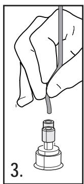
Illustration of hands connecting a pipe to a connector with arrows indicating direction (no text or symbols)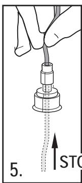
text_image
5. STC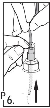
text_image
P 6.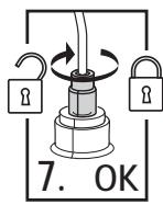
text_image
7. OK
natural_image
Line drawing of a hand holding a smartphone with a speech bubble (no text or symbols)EN "Download the ELICA CONNECT APP to enjoy all the advantages of your connected product. Follow the instructions in the leaflet attached to the product"
natural_image
Line drawing of a speaker with sound waves, no text or symbols presentEN "You can control your Elica hood with voice commands. Use the ELICA CONNECT APP to discover which voice assistants your hood is compatible with."
natural_image
Icon showing a stopper above a wireless signal icon with an open remote (no text or symbols)Closely follow the instructions set out in this manual. All responsibility, for any eventual inconveniences, damages or fires caused by not complying with the instructions in this manual, is declined. This appliance is intended to be used in household and similar application such as: - staff kitchen areas in shop, offices and other working environments; - farm houses; - by clients in hotels, motels and other residential type environments; - bed and breakfast type environments.
The hood can look different to that illustrated in the drawings in this booklet. The instructions for use, maintenance and installation, however, remain the same.
- It is important to conserve this booklet for consultation at any moment. In the case of sale, cession or move, make sure it is together with the product.
- Read the instructions carefully: there is important information about installation, use and safety.
- Do not carry out electrical or mechanical variations on the product or on the discharge conduits.
- Before proceeding with the installation of the appliance verify that there are no damaged all components. Otherwise contact your dealer and do not proceed with the installation.
Note: The parts marked with the symbol “(*)” are optional accessories supplied only with some models or otherwise not supplied, but available for purchase.

Caution
- Before any cleaning or maintenance operation, disconnect hood from the mains by removing the plug or disconnecting the mains electrical supply.
• Always wear work gloves for all installation and maintenance operations. - This appliance can be used by children aged from 8 years and above and persons with reduced physical, sensory or mental capabilities or lack of experience and knowledge if they have been given supervision or instruction concerning use of the appliance in a safe way and understand the hazards involved.
• Children shall not be allowed to tamper with the controls or play with the appliance. - Cleaning and user maintenance shall not be made by children without supervision.
• The premises where the appliance is
installed must be sufficiently ventilated, when the kitchen hood is used together with other gas combustion devices or other fuels.
- The hood must be regularly cleaned on both the inside and outside (AT LEAST ONCE A MONTH).
- This must be completed in accordance with the maintenance instructions provided. Failure to follow the instructions provided regarding the cleaning of the hood and filters will lead to the risk of fires.
- Do not flambé under the range hood.
- Do not remove filters during cooking.
- For lamp replacement use only lamp type indicated in the Maintenance/Replacing lamps section of this manual.
The use of exposed flames is detrimental to the filters and may cause a fire risk, and must therefore be avoided in all circumstances.
Any frying must be done with care in order to make sure that the oil does not overheat and ignite.
CAUTION: Accessible parts of the hood may become hot when used with cooking appliances.
- Do not connect the appliance to the mains until the installation is fully complete.
- With regards to the technical and safety measures to be adopted for fume discharging it is important to closely follow the regulations provided by the local authorities.
- The air must not be discharged into a flue that is used for exhausting fumes from appliance burning gas or other fuels.
▲ WARNING! Failure to install the screws or fixing device in accordance with these instructions may result in electrical hazards.
- Do not use or leave the hood without the lamp correctly mounted due to the possible risk of electric shocks.
- Never use the hood without effectively mounted grids.
- The hood must NEVER be used as a support surface unless specifically indicated.
- Use only the fixing screws supplied with the product for installation or, if not supplied, purchase the correct screws type.
- Use the correct length for the screws which are identified in the Installation Guide.
• In case of doubt, consult an authorized service assistance center or similar qualified person.
⚠ WARNING! Do not use with a programmer, timer, separate remote control system or any other device that switches on automatically.
Electrical connection
The mains power supply must correspond to the rating indicated on the plate situated inside the hood. If provided with a plug connect the hood to a socket in compliance with current regulations and positioned in an accessible area, after installation. If it not fitted with a plug (direct mains connection) or if the plug is not located in an accessible area, after installation, apply a double pole switch in accordance with standards which assures the complete disconnection of the mains under conditions relating to over-current category III, in accordance with installation instructions.
⚠ WARNING! Before re-connecting the hood circuit to the mains supply and checking the efficient function, always check that the mains cable is correctly assembled.
Installation
- The minimum distance between the supporting surface for the cooking equipment on the hob and the lowest part of the range hood must be not less than 70cm from electric cookers and 100cm from gas or mixed cookers.
If the instructions for installation for the gas hob specify a greater distance, this must be adhered to.
- This appliance is marked according to the European directive 2012/19/EC - UK SI 2013 No.3113 on Waste Electrical and Electronic Equipment (WEEE). - By ensuring this product is disposed of correctly, you will help prevent potential negative consequences for the environment and human health, which could otherwise be caused by inappropriate waste handling of this product.

- The symbol ■ on the product, or on the documents accompanying the product, indicates that this appliance may not be treated as household waste. Instead it should be taken to the appropriate collection point for the recycling of electrical and electronic equipment. Disposal must be carried out in accordance with local environmental regulations for waste disposal.
- For further detailed information regarding the process, collection and recycling of this product, please contact the appropriate department of your local authorities or the local department for household waste or the shop where you purchased this product.
Appliance designed, tested and manufactured according to:
- Safety: EN/IEC 60335-1; EN/IEC 60335-2-31, EN/IEC 62233.
• Performance: EN/IEC 61591; ISO 5167-1; ISO 5167-3; ISO 5168; EN/IEC 60704-1; EN/IEC 60704-2-13; EN/IEC 60704-3; ISO 3741; EN 50564; IEC 62301.
- EMC: EN 55014-1; CISPR 14-1; EN 55014-2; CISPR 14-2; EN/IEC 61000-3-2; EN/IEC 61000-3-3; ETSI EN 301 489-1; ETSI EN 301 489-17; ETSI EN 300 328; IEC 62311:2019. Suggestions for a correct use in order to reduce the environmental impact: Switch ON the hood at minimum speed when you start cooking and kept it running for few minutes after cooking is finished. Increase the speed only in case of large amount of smoke and vapor and use boost speed(s) only in extreme situations. Replace the charcoal filter(s) when necessary to maintain a good odor reduction efficiency. Clean the grease filter(s) when necessary to maintain a good grease filter efficiency. Use the maximum diameter of the ducting system indicated in this manual to optimize efficiency and minimize noise.
If the product exterior is made using a special material, which is non-standard for the type of hood application, such as Wood, Porcelain stone and Krion, any distinctive marks, differences in colour and surface deformations shall not be considered as defects but rather a characteristic of the material itself.
In the specific case of wood, this is a noble, natural and living material that tends to change over time. This makes each product unique and unrepeatable.
Use
The hood is designed to be used for exhausting version.
In this case the fumes are conveyed outside of the building by means of a special pipe connected with the connection ring located on top of the hood.

CAUTION!
The exhausting pipe is not supplied and must be purchased apart.
Diameter of the exhausting pipe must be equal to that of the connection ring.

CAUTION!
If the hood is supplied with active charcoal filter, then it must be removed.
Connect the hood and discharge holes on the walls with a diameter equivalent to the air outlet (connection flange).
Using the tubes and discharge holes on walls with smaller dimensions will cause a diminution of the suction performance and a drastic increase in noise.
Any responsibility in the matter is therefore declined.
! Use a duct of the minimum indispensable length.
! Use a duct with as few elbows as possible (maximum elbow angle: 90°).
! Avoid drastic changes in the duct cross-section.
Elica Connect
The hood features a WiFi function for remote connection via the Elica Connect app.
Minimum system requirements:
• 2.4GHz WiFi b/g/n wireless router
- Android or iOS Smartphone. Via the stores, check that the app is compatible with the operating system your Smartphone is running.
Note: The ELICA manufacturer declares that this model of household appliance with WiFi module radio equipment complies with Directive 2014/53/EU.
The radio equipment operates within the 2.4GHz ISM frequency band, the maximum radio frequency power transmitted does not exceed 20 dBm (e.i.r.p.).
Warnings:
- Data protection. The data that the connected device detects is collected to allow for all the services of the connected appliance to be used. Further information on how the collected data is processed and on the privacy policy is available at www.elica.com.
• Availability in different countries. The Elica Connect service is available in specific countries. For further information, see the dedicated section at www.elica.com. - Future changes. Elica reserves the right to make any changes deemed useful to improve the Elica Connect service. As a result, the descriptions contained in this manual are not binding and should be treated as purely indicative.
Operation
natural_image
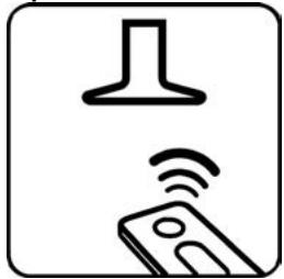
Icon showing a device with wireless signal waves and a stopper (no text or symbols)This product is designed to work with an Elica remote control, either supplied with the product or purchased separately as an optional.
To control the hood via remote control, the affiliation procedure must be carried out.
CAUTION!
To begin, the hood must be disconnected and then reconnected to the power supply and the affiliation procedure must be carried out within the first minute of connection to the power.
Read the instructions supplied with the remote control, which provide detailed instructions on affiliation and correct use.
Remote control connection (if applicable)
Once the remote control has been connected, this will be displayed on the hood: both LEDs flash.
Indicator LED on hood
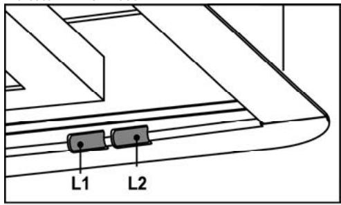
text_image
L1 L2Note: the Speed 4 (and the Speed 5, where applicable) if selected, will activate for a limited period of time after which Speed 2 is automatically enabled.
Note: Using the remote control, delayed shut-down can be programmed based on the aspiration speed (power) enabled at that moment:
Speed 1 (low aspiration): 20 minutes
Speed 2 (medium aspiration): 15 minutes
Speed 3 (high aspiration): 10 minutes
Note (for hoods with WiFi):
The ELICA CONNECT App allows advanced management of the delayed shut-down function, follow the instructions in the App.
Attention: in hoods with WiFi, the delayed shut-down function can be managed via remote control only if the hood WiFi function is not active.
WiFi
- WiFi configuration: Follow the instructions provided in the ELICA CONNECT App for the WiFi configuration.
During the configuration procedure, the LED L1 of the hood will light up to indicate the connectivity status (see "WiFi status table" below)
To interrupt the WiFi configuration procedure, press key A on the remote control for about 2 seconds when the LED L1 of the hood is on and flashing quickly.
Once the WiFi function has been configured, if it needs to be changed, hold keys A+B on the remote control for about 2 seconds to reset the WiFi parameters (the key turns off) and repeat the configuration procedure.
- WiFi activation/deactivation: after the configuration, it is possible to deactivate/activate the WiFi function. Press A for about 2 seconds to deactivate/activate the WiFi function.
Deactivating the function does not cause the loss of the WiFi parameters.
- WiFi status table
| WiFi LED hood (L1) | Device connection status |
| Light off | WiFi not configured or off |
| White light on steady | WiFi connected |
| Orange light flashing fast | Attempt to connect to the WiFi router |
| Orange light flashing slowly | Attempt to connect to the Elica cloud |
| White light on with short flashing light | Remote command being received (e.g. engine ignition or light turned on) |
Filter Saturation indicator lights
At regular intervals, the LEDs on the hood indicate the need to carry out filter maintenance.
Note: The filter saturation signal is visible for a few seconds when the hood is switched on; within this time, the saturation indicator lights must be reset.
Flashing Green LED: carry out maintenance on the grease filter.
Red flashing LED: carry out maintenance on the charcoal
filter (only for hoods operating in "Filtration Version").
Note: Run the "RESET FILTRES" command via the remote control.
Activating/deactivating the filter saturation indicator light
Note: Run the procedure with the hood switched off. The charcoal filter saturation indicator light is usually deactivated.
If no control is given within maximum 10 sec, the hood automatically exits this function, at any time, and returns to the previous state.
Press and hold the B+C keys (Simultaneously) to enter the setup menu:
Briefly press button C to select the filter to be set up:
Grease filter: Green
Charcoal filter: Red
Briefly press button B to activate (the 2nd LED flashing) or deactivate (2nd LED off).
Note: the LEDs light up for a limited number of seconds after which they turn off to indicate that the indicator light has been activated (or deactivated).
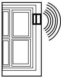
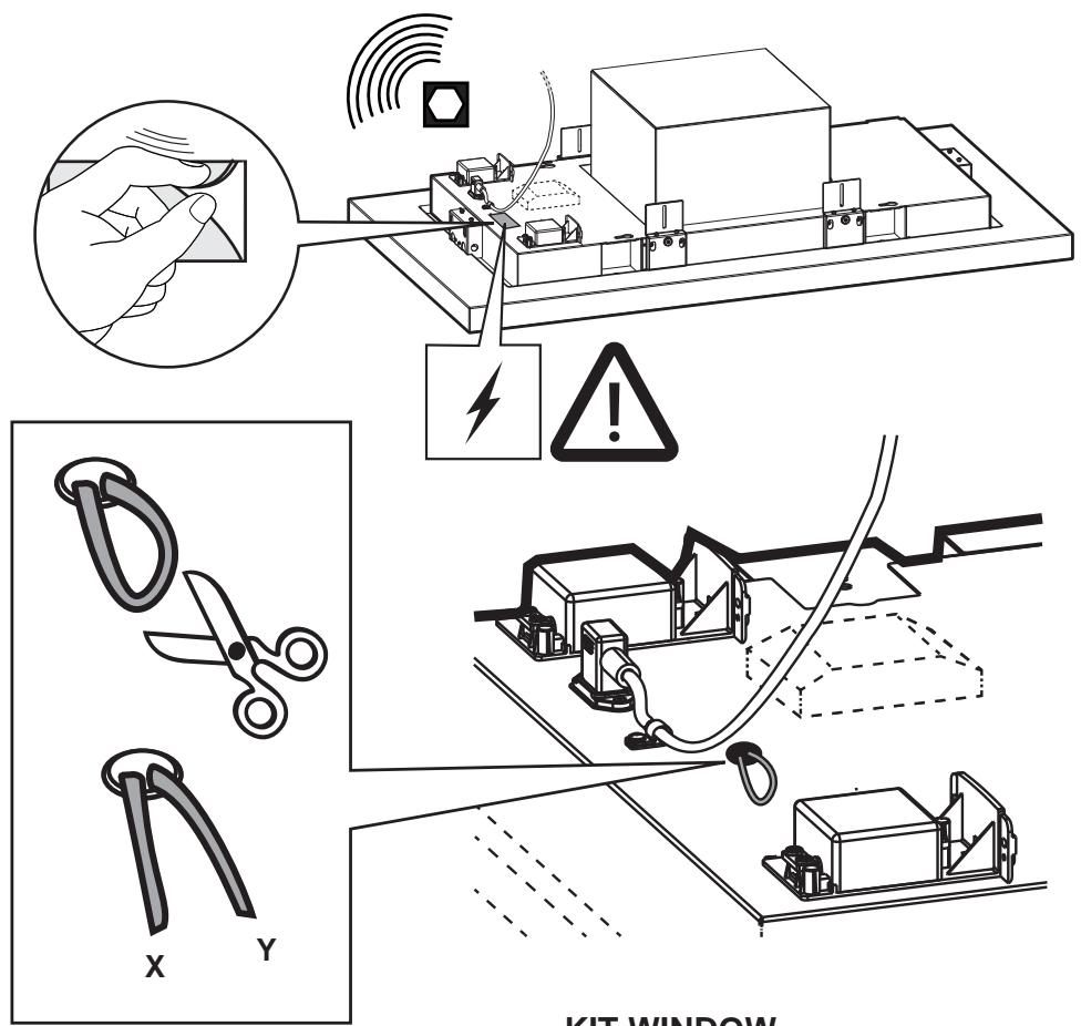
The device can also be used in combination with a Window sensor KIT (not supplied by the manufacturer).
If the Window sensor KIT is installed (only in the case of use in EXTRACTOR mode), air extraction will halt every time the window in the room, on which the KIT is applied, is closed.
- The KIT must be electrically connected to the device by qualified and specialised technical personnel.
- The KIT must be certified separately in accordance with the safety standards for the component and its use with the device. Installation must be carried out in accordance with current regulations for domestic systems.
PLEASE NOTE:
- the wiring of the KIT to be connected to the device must be part of a certified safety extra-low voltage (SELV) circuit.
- the manufacturer of this device declines all liability for any inconvenience, damage or fires caused by defects and/or problems associated with the malfunction and/or incorrect installation of the KIT.
Maintenance
Cleaning
Clean using ONLY a cloth dampened with neutral liquid detergent. DO NOT CLEAN WITH TOOLS OR INSTRUMENTS. Do not use abrasive products. DO NOT USE ALCOHOL!
Panel
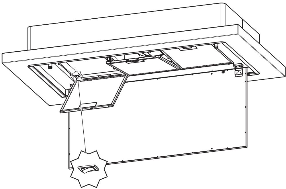
Fig. 9
The panel for perimeter suction should always be left closed and should only be opened in case of maintenance interventions (eg cleaning or replacing filters).
Grease filter
Fig. 9
Traps cooking grease particles.
This must be cleaned once a month (or when the filter saturation indication system – if envisaged on the model in possession – indicates this necessity) using non aggressive detergents, either by hand or in the dishwasher, which must be set to a low temperature and a short cycle.
When washed in a dishwasher, the grease filter may discolor slightly, but this does not affect its filtering capacity.
To remove the grease filter, pull the spring release handle.
Replacing lamps
The hood is equipped with a lighting system based on LED technology.
The LEDs guarantee an optimum lighting, a duration up to 10 times longer than the traditional lamps and allow to save 90% electrical energy.
For replacement, contact the technical service.