USER MANUAL OPEN SUITE ELICA
EN Instruction on mounting and use
natural_image
Warning symbol with exclamation mark inside a triangle (no text or numbers)

natural_image
Three identical black silhouette figures of human figures, no text or symbols present

natural_image
Illustration of two gloves, one open and one closed, with no text or symbols present.
natural_image
Line drawing of a multi-tiered storage cabinet with two doors and a rack base (no text or symbols)
natural_image
Line drawing of a multi-tiered storage cabinet with two doors and a grater base (no text or symbols)
natural_image
Line drawing of a two-tiered storage cabinet with labeled sections (SX) and (DX), no text or symbols on the cabinet itself.
natural_image
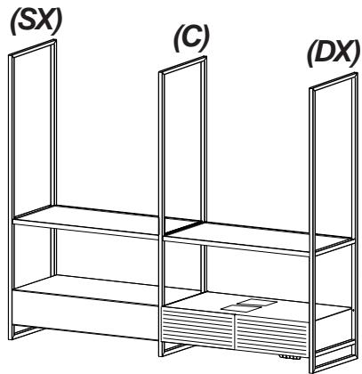
Line drawing of a two-tiered storage unit with labeled sections (SX, C, DX), no text or symbols present.

natural_image
Line drawing of a two-tiered storage shelf with one shelf open and one on the side (no text or symbols)
natural_image
Line drawing of a multi-level storage cabinet with metal frame and drawer (no text or symbols)

natural_image
Architectural diagram showing two multi-level building layouts with structural elements and directional arrows (no text or symbols)

3x MAX
natural_image
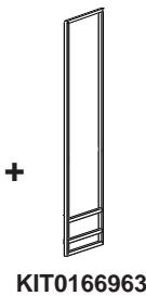
Simple line drawing of a vertical panel with a plus sign and label 'KIT0166963' below (no other text or symbols)
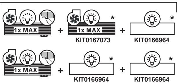
KIT0167073 = Type: E128 I 2K42G 1SE B
KIT0166964 = Type: E128 I 1SE B
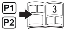
flowchart
graph LR
    P1["Box P1"] --> Box["Box 3"]
    P2["Box P2"] --> Box["Box 3"]
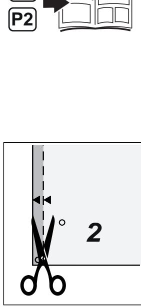
2
flowchart
graph TD
    A["P1"] --> C["3"]
    B["P2"] --> C["3"]
natural_image
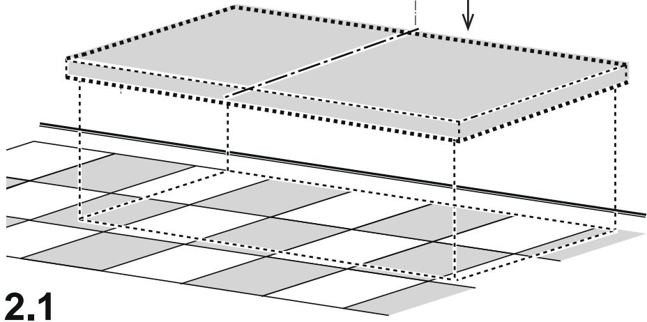
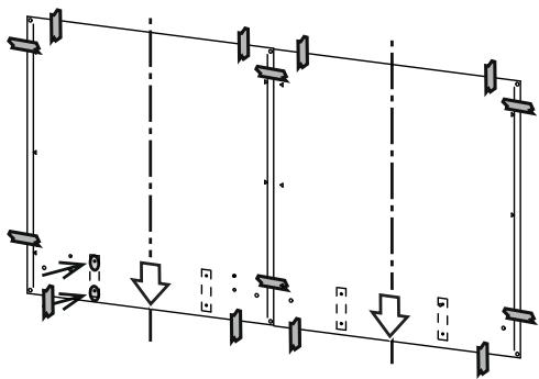
3D diagram showing a layered structure with grid patterns and a downward arrow, labeled '2.1' (no text or symbols on the diagram itself)
flowchart
graph TD
    A["Device with V-Hz"] --> B["Signal transmission"]
    B --> C{P1 P2}
    C --> D["Output: V-Hz"]
    D --> E["Final reception"]
    style A fill:#f9f,stroke:#333
    style E fill:#bbf,stroke:#333
natural_image
Line drawing of a two-tiered storage cabinet or rack unit (no text or symbols)
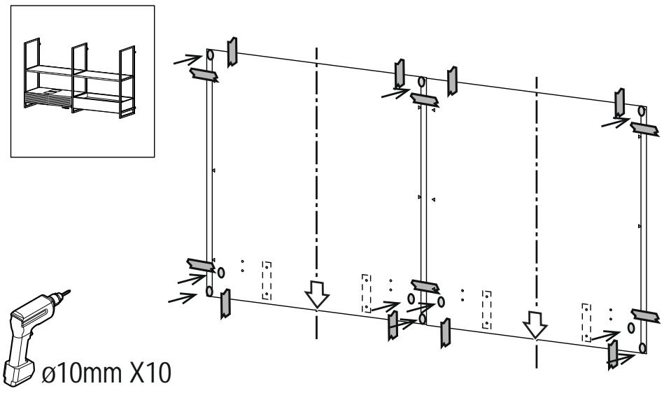
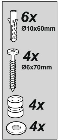
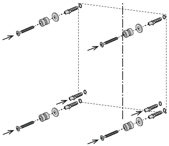
ø10mm X6
4

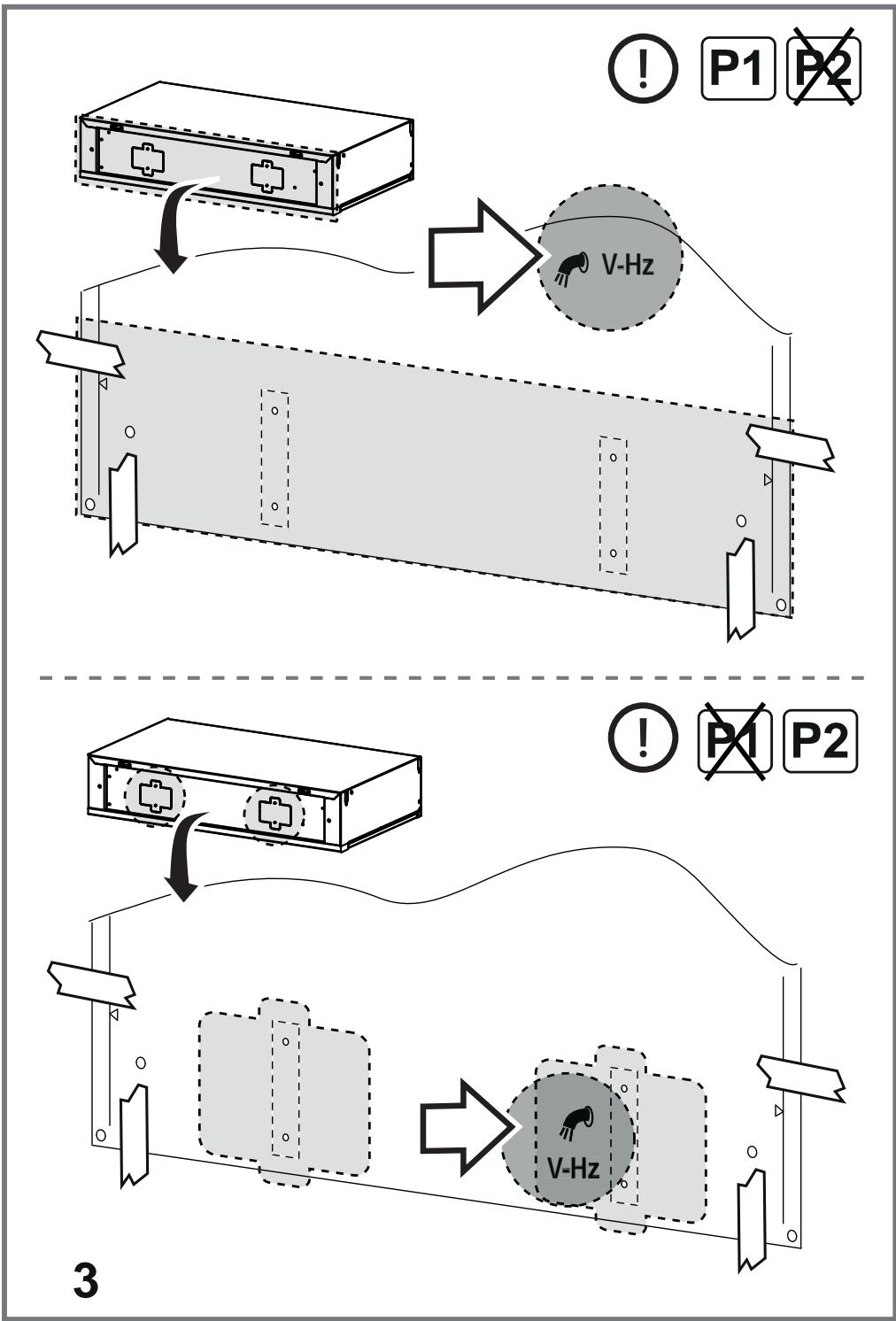
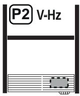
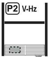
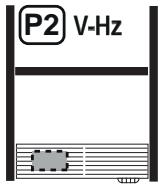
P2
natural_image
Line drawing of a two-tiered storage cabinet or rack unit (no text or symbols)
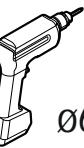
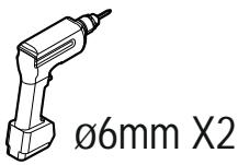
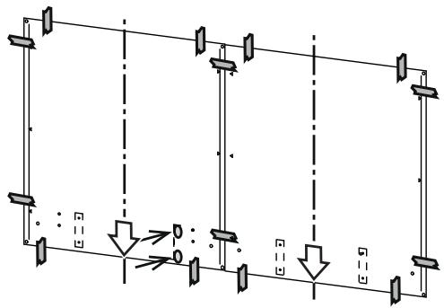
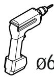
∅6mm X2
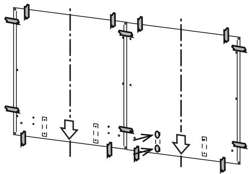
4.1

natural_image
Pure electrical circuit lines without any symbols
natural_image
Pure electrical circuit lines without any symbols

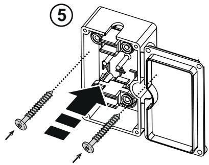
5

natural_image
Line drawing of a three-tiered shelving unit (no text or symbols)
flowchart
graph TD
    A["Switch"] --> B["Load"]
    B --> C{Switch}
    C --> D["Load"]
    D --> E["Output"]
    style A fill:#f9f,stroke:#333
    style E fill:#bbf,stroke:#333
flowchart
graph TD
    A["Switch"] --> B["Branch 1"]
    B --> C["Switch"]
    C --> D["Branch 2"]
    D --> E["Switch"]
    E --> F["Switch"]
    F --> G["Switch"]
    G --> H["Switch"]
    H --> I["Switch"]
    I --> J["Switch"]
    J --> K["Switch"]
    K --> L["Switch"]
    L --> M["Switch"]
    M --> N["Switch"]
    N --> O["Switch"]
    O --> P["Switch"]
    P --> Q["Switch"]
    Q --> R["Switch"]
    R --> S["Switch"]
    S --> T["Switch"]
    T --> U["Switch"]
    U --> V["Switch"]
    V --> W["Switch"]
    W --> X["Switch"]
    X --> Y["Switch"]
    Y --> Z["Switch"]
5.1
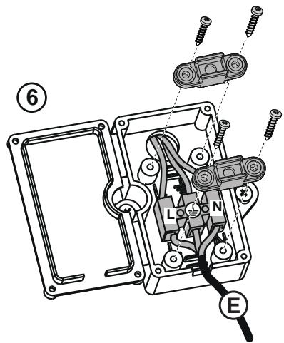
6

P2
natural_image
Simple line drawing of a two-tiered shelving unit (no text or symbols)
flowchart
graph TD
    A["Switch"] --> B["Component 1"]
    A --> C["Component 2"]
    A --> D["Component 3"]
    A --> E["Component 4"]
    B --> F["Load"]
    C --> G["Load"]
    D --> H["Load"]
    E --> I["Load"]

ø6mm X2
natural_image
Pure electrical circuit lines without any symbols
6.1
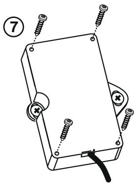
7
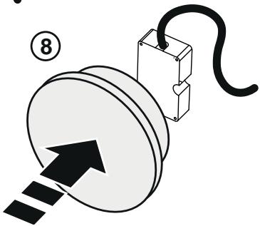
8
natural_image
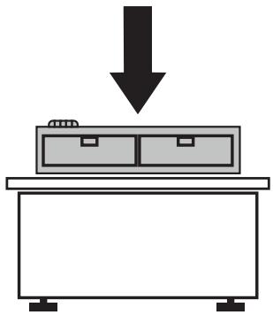
Simple diagram showing a downward arrow pointing to a box on a table (no text or symbols)
9
11
12
13
14
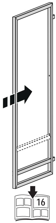
15


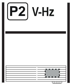
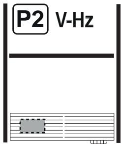
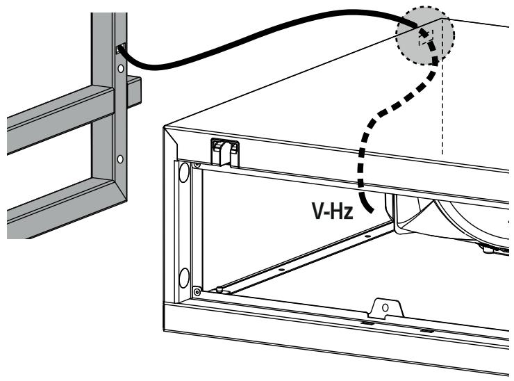
V-Hz


P2


V-Hz
natural_image
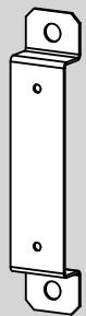
Technical line drawing of a rectangular metal bracket with mounting holes (no text or symbols)
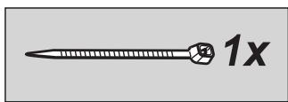
1x
2x
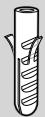
∅6x30mm
2x
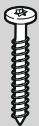
∅4,5x36mm

2x
∅3,5x9,5mm
1x


P2
natural_image
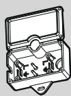
Line drawing of a hand inserting a component into a rectangular device with two cross-shaped buttons (no text or symbols)
18
natural_image
Simple line drawing of a plastic box transforming into a trash bin (no text or symbols)
P1

19

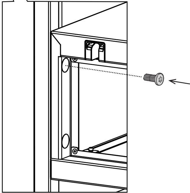
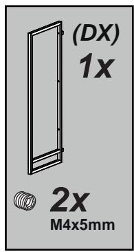
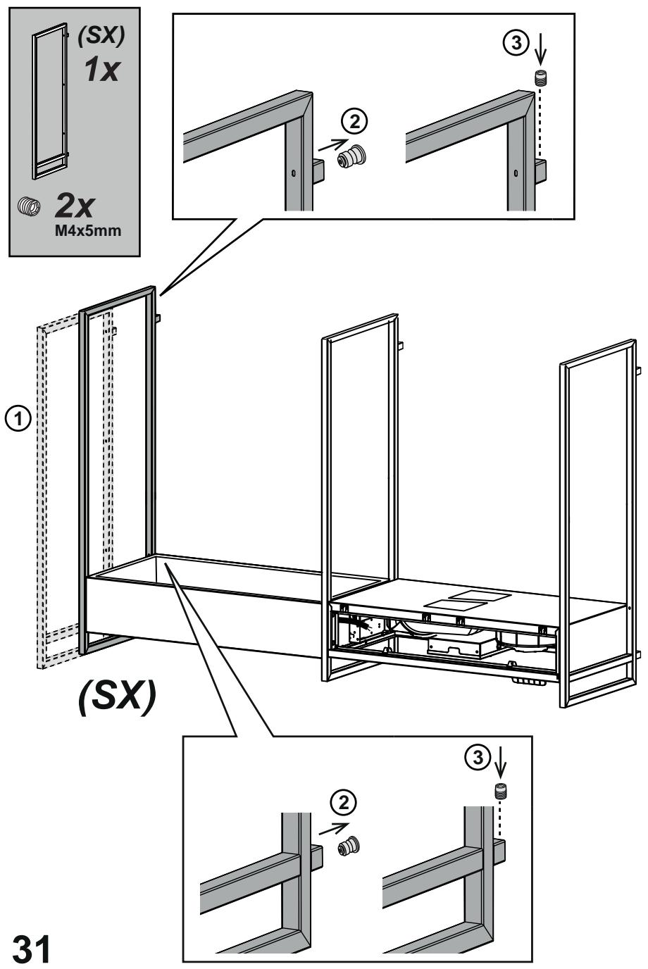
2x
M4x5mm
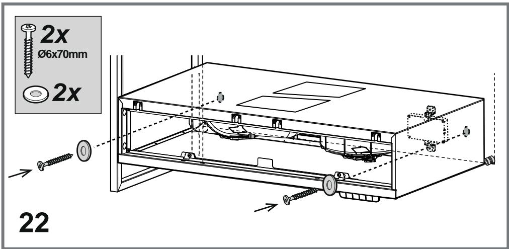
21
natural_image
Technical line drawing of a cabinet or enclosure with internal components and mounting holes (no text or symbols)

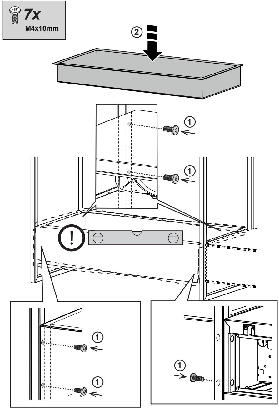
1x
M4x10mm
natural_image
Technical line drawing of a mechanical assembly with internal components and mounting brackets (no text or symbols)
natural_image
Technical line drawing of a mechanical assembly with a bolt and mounting bracket (no text or symbols)
natural_image
Technical line drawing of a mechanical assembly with no visible text or symbols
24


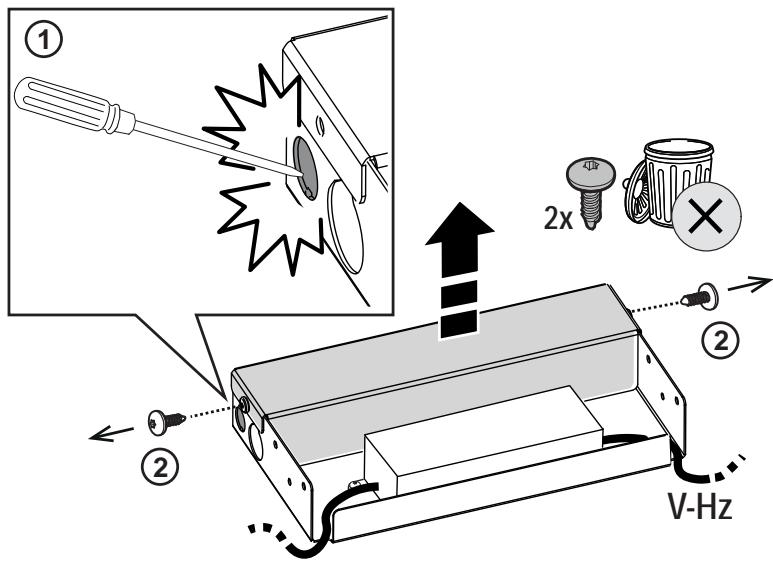
V-Hz


V-Hz
natural_image
Technical line drawing of a mechanical assembly with a coiled cable and mounting bracket (no text or symbols)


V-Hz
34


2x
∅6x30mm
1x

2x

8x
∅2,9x9,5mm
2x
∅4,5x36mm
1x
natural_image
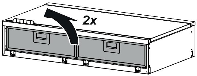
Technical line drawing of a cabinet with two doors and a circular opening, no text or symbols present
natural_image
Technical diagram of a mechanical device with internal components and a downward arrow indicating motion (no text or symbols)


V-Hz
natural_image
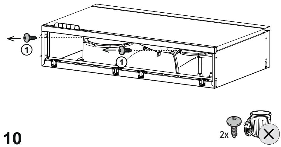
Simple line drawing of a rectangular device with screws and a cable, no text or symbols present
natural_image
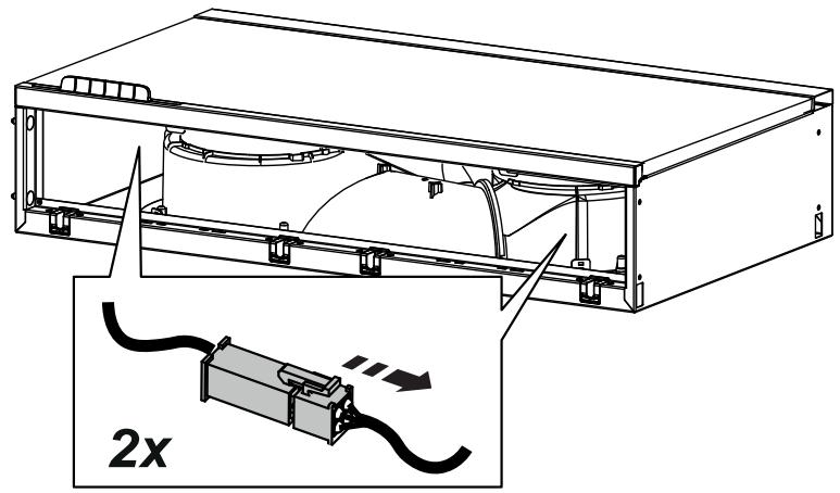
Diagram of a pulley system with an attached circuit board and directional arrow (no text or symbols)
35.1

P2


V-Hz

8x
∅2,9x9,5mm
natural_image
Line drawing of a two-panel cabinet or enclosure with open doors and internal compartments (no text or symbols)
natural_image
Technical diagram of a mechanical assembly with wiring and components, showing a housing and base plate (no text or symbols)
38
39
40
flowchart
graph TD
    A["Step ①"] --> B["Step ②"]
    B --> C["Final State"]
    style A fill:#f9f,stroke:#333
    style B fill:#ccf,stroke:#333
    style C fill:#cfc,stroke:#333
natural_image
Simple diagram showing a rectangular block with a gear-like edge and a downward arrow, no text or symbols present.
natural_image
Line drawing of a multi-tiered storage unit with horizontal shelves and a small panel, no text or symbols present
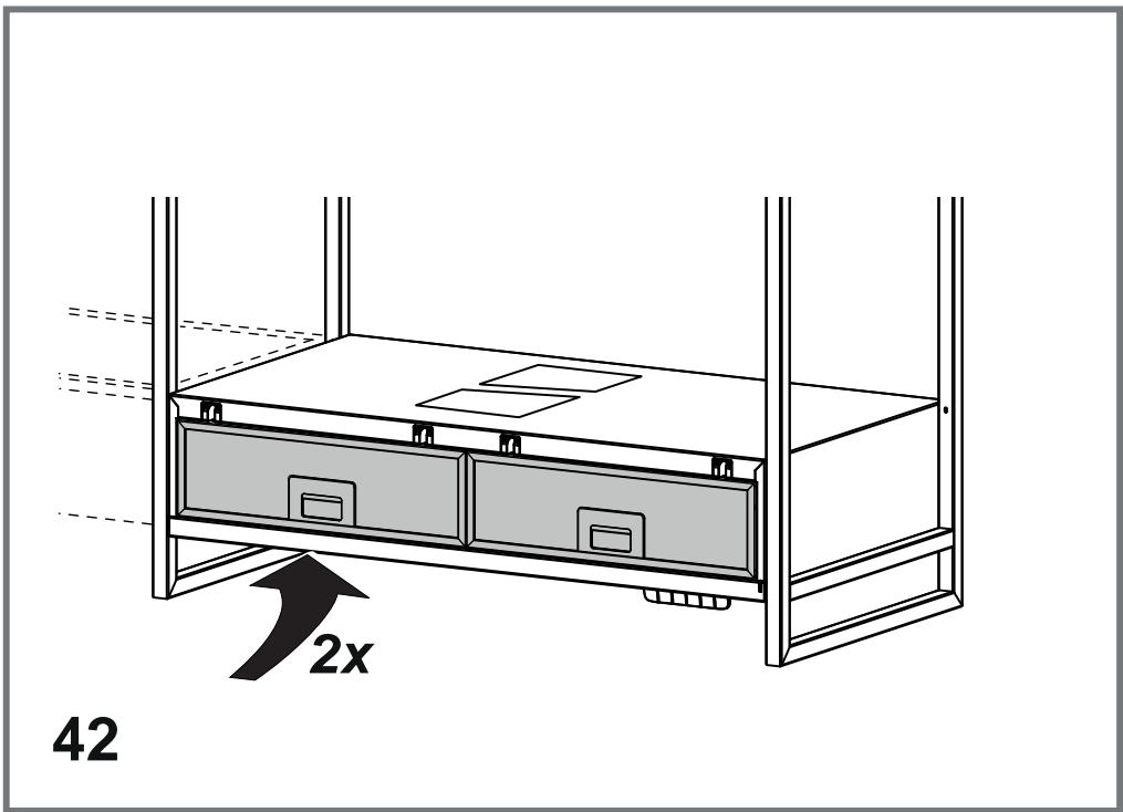
44
natural_image
Technical line drawing of a multi-tiered storage cabinet with heat exchanger (no text or symbols)
45

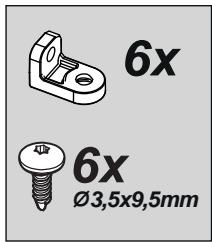
8x

8x
∅3,5x9,5mm

natural_image
Technical line drawing of a mechanical assembly with two labeled components above a base panel (no text or symbols present)
natural_image
Technical line drawing of a multi-level storage cabinet with open doors and internal compartments (no text or symbols)
natural_image
Technical line drawing of a multi-level storage shelf with no text or symbols
50
51
natural_image
Technical line drawing of a mechanical assembly with a numbered component (4) and directional arrow, no text or symbols present.
55
56

natural_image
Line drawing of a hand holding a smartphone with a speech bubble (no text or symbols)
EN "Download the ELICA CONNECT APP to enjoy all the advantages of your connected product. Follow the instructions in the leaflet attached to the product"
natural_image
Line drawing of a speaker with sound waves, no text or symbols present
EN "You can control your Elica hood with voice commands. Use the ELICA CONNECT APP to discover which voice assistants your hood is compatible with."
Closely follow the instructions set out in this manual. All responsibility, for any eventual inconveniences, damages or fires caused by not complying with the instructions in this manual, is declined. This appliance is intended to be used in household and similar application such as: - staff kitchen areas in shop, offices and other working environments; - farm houses; - by clients in hotels, motels and other residential type environments; - bed and breakfast type environments.
The hood can look different to that illustrated in the drawings in this booklet. The instructions for use, maintenance and installation, however, remain the same.
- It is important to conserve this booklet for consultation at any moment. In the case of sale, cession or move, make sure it is together with the product.
- Read the instructions carefully: there is important information about installation, use and safety.
- Do not carry out electrical or mechanical variations on the product or on the discharge conduits.
- Before proceeding with the installation of the appliance verify that there are no damaged all components. Otherwise contact your dealer and do not proceed with the installation.
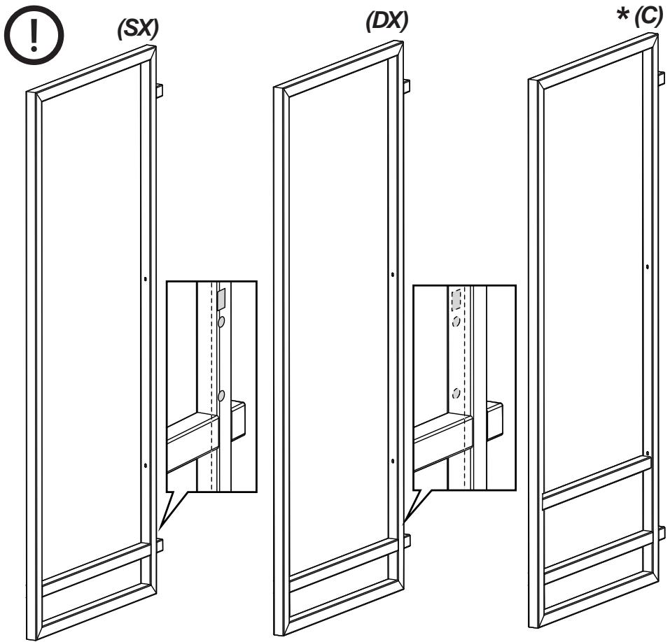
Note: The parts marked with the symbol “(*)” are optional accessories supplied only with some models or otherwise not supplied, but available for purchase.

Caution
- Before any cleaning or maintenance operation, disconnect hood from the mains by removing the plug or disconnecting the mains electrical supply.
• Always wear work gloves for all installation and maintenance operations.
- This appliance can be used by children aged from 8 years and above and persons with reduced physical, sensory or mental capabilities or lack of experience and knowledge if they have been given supervision or instruction concerning use of the appliance in a safe way and understand the hazards involved.
• Children shall not be allowed to tamper with the controls or play with the appliance.
- Cleaning and user maintenance shall not be made by children without supervision.
- The premises where the appliance is installed must be sufficiently ventilated, when the kitchen hood is used together with other gas combustion devices or other
fuels.
- The hood must be regularly cleaned on both the inside and outside (AT LEAST ONCE A MONTH).
- This must be completed in accordance with the maintenance instructions provided. Failure to follow the instructions provided regarding the cleaning of the hood and filters will lead to the risk of fires.
- Do not flambé under the range hood.
- Do not remove filters during cooking.
- For lamp replacement use only lamp type indicated in the Maintenance/Replacing lamps section of this manual.
The use of exposed flames is detrimental to the filters and may cause a fire risk, and must therefore be avoided in all circumstances.
Any frying must be done with care in order to make sure that the oil does not overheat and ignite.
CAUTION: Accessible parts of the hood may become hot when used with cooking appliances.
- Do not connect the appliance to the mains until the installation is fully complete.
- With regards to the technical and safety measures to be adopted for fume discharging it is important to closely follow the regulations provided by the local authorities.
- The air must not be discharged into a flue that is used for exhausting fumes from appliance burning gas or other fuels.
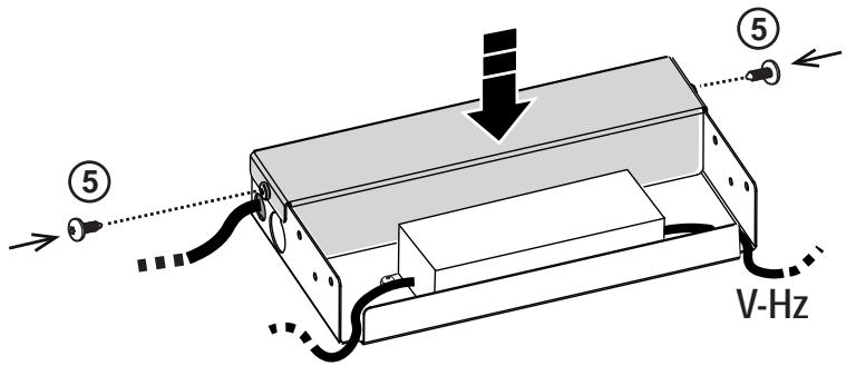
⚠ WARNING! Failure to install the screws or fixing device in accordance with these instructions may result in electrical hazards.
- Do not use or leave the hood without the lamp correctly mounted due to the possible risk of electric shocks.
- Never use the hood without effectively mounted grids.
- The hood must NEVER be used as a support surface unless specifically indicated.
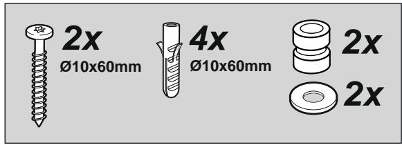
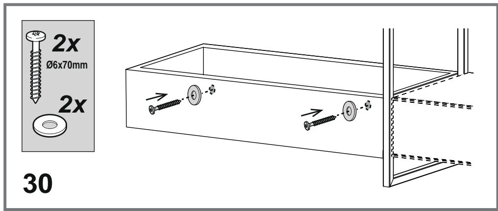
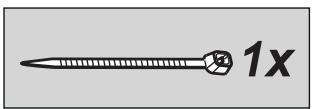
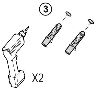
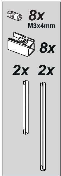
- Use only the fixing screws supplied with the product for installation or, if not supplied, purchase the correct screws type.
- Use the correct length for the screws which are identified in the Installation Guide.
- In case of doubt, consult an authorized service assistance center or similar qualified person.
⚠ WARNING! Do not use with a programmer, timer, separate remote control system or any other device that switches on automatically.
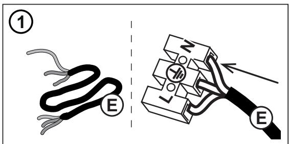
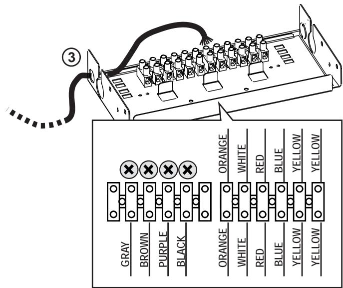
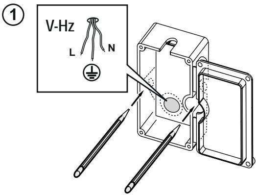
Electrical connection
The mains power supply must correspond to the rating indicated on the plate situated inside the hood. If provided with a plug connect the hood to a socket in compliance with current regulations and positioned in an accessible area, after installation. If it not fitted with a plug (direct mains connection) or if the plug is not located in an accessible area, after installation, apply a double pole switch in accordance with standards which assures the complete disconnection of the mains under conditions relating to over-current category III, in accordance with installation instructions.
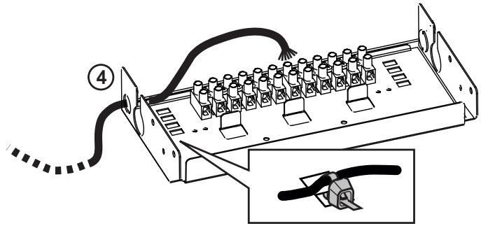
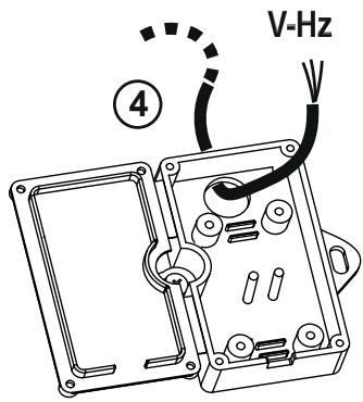
⚠ WARNING! Before re-connecting the hood circuit to the mains supply and checking the efficient function, always
check that the mains cable is correctly assembled.
The hood must be connected to the mains supply by qualified and trained technicians.
Installation
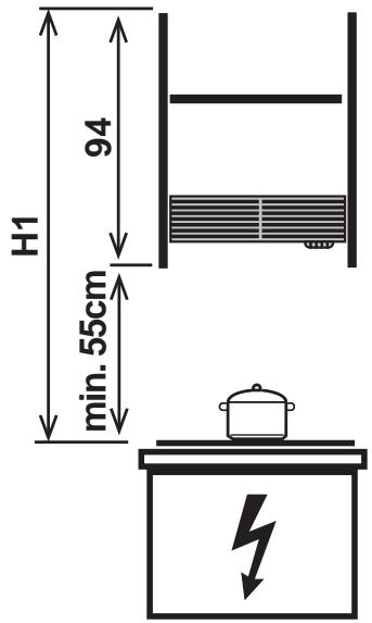
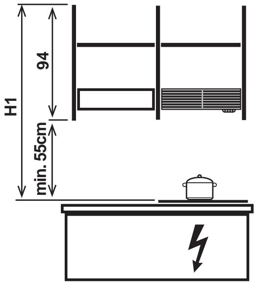
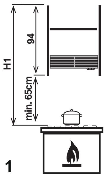
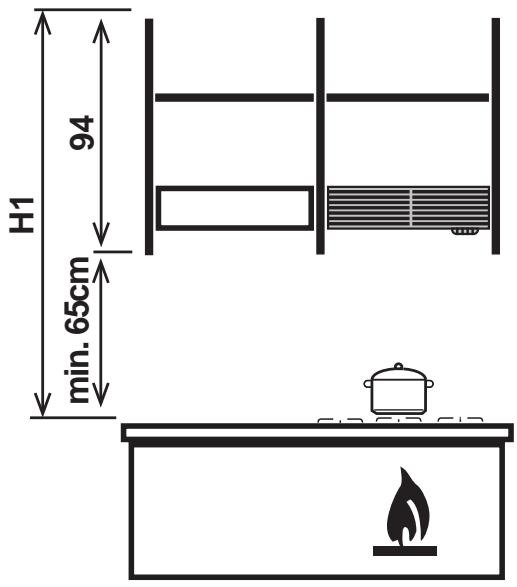
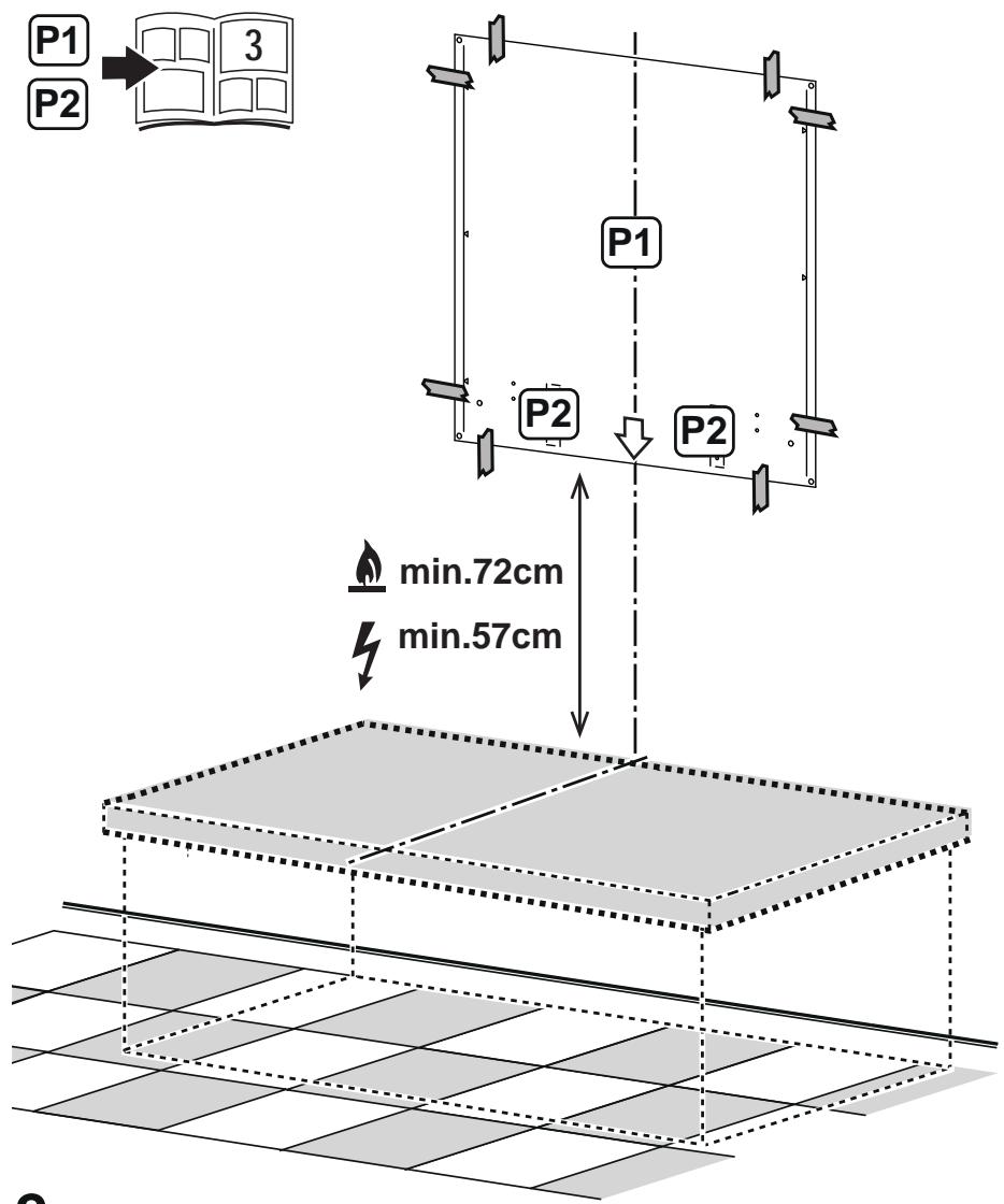
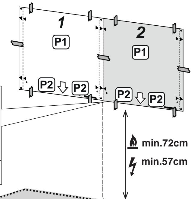
- The minimum distance between the supporting surface for the cooking equipment on the hob and the lowest part of the range hood must be not less than 55cm from electric cookers and 65cm from gas or mixed cookers.
If the instructions for installation for the gas hob specify a greater distance, this must be adhered to.
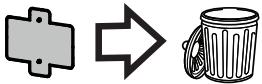
- This appliance is marked according to the European directive 2012/19/EC - UK SI 2013 No.3113 on Waste Electrical and Electronic Equipment (WEEE).
- By ensuring this product is disposed of correctly, you will help prevent potential negative consequences for the environment and human health, which could otherwise be caused by inappropriate waste handling of this product.

- The symbol ____ on the product, or on the documents accompanying the product, indicates that this appliance may not be treated as household waste. Instead it should be taken to the appropriate collection point for the recycling of electrical and electronic equipment. Disposal must be carried out in accordance with local environmental regulations for waste disposal.
- For further detailed information regarding the process, collection and recycling of this product, please contact the appropriate department of your local authorities or the local department for household waste or the shop where you purchased this product.
Appliance designed, tested and manufactured according to:
• Safety: EN/IEC 60335-1; EN/IEC 60335-2-31, EN/IEC 62233.
• Performance: EN/IEC 61591; ISO 5167-1; ISO 5167-3; ISO 5168; EN/IEC 60704-1; EN/IEC 60704-2-13; EN/IEC 60704-3; ISO 3741; EN 50564; IEC 62301.
- EMC: EN 55014-1; CISPR 14-1; EN 55014-2; CISPR 14-2; EN/IEC 61000-3-2; EN/IEC 61000-3-3; ETSI EN 301 489-1; ETSI EN 301 489-17; ETSI EN 300 328; IEC 62311:2019.
Suggestions for a correct use in order to reduce the environmental impact: Switch ON the hood at minimum speed when you start cooking and kept it running for few minutes after cooking is finished. Increase the speed only in case of large amount of smoke and vapor and use boost speed(s) only in extreme situations. Replace the charcoal filter(s) when necessary to maintain a good odor reduction efficiency. Clean the grease filter(s) when necessary to maintain a good grease filter efficiency. Use the
maximum diameter of the ducting system indicated in this manual to optimize efficiency and minimize noise.
Use

Filtration version
The aspirated air will be degreased and deodorised before being fed back into the room.
In order to use the hood in this version, you have to install a system of additional filtering based on activated charcoal.
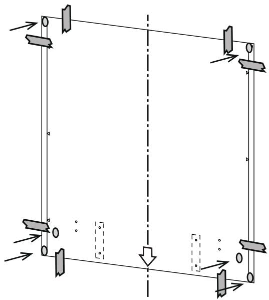
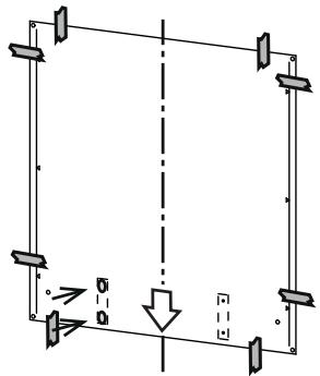
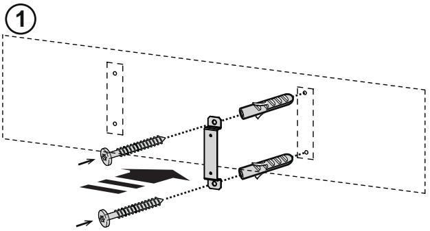
Mounting
Before beginning installation:
- Check that the product purchased is of a suitable size for the chosen installation area.
- Remove the charcoal (*) filter/s if supplied (see also relative paragraph). This/these is/are to be mounted only if you want lo use the hood in the filtering version.
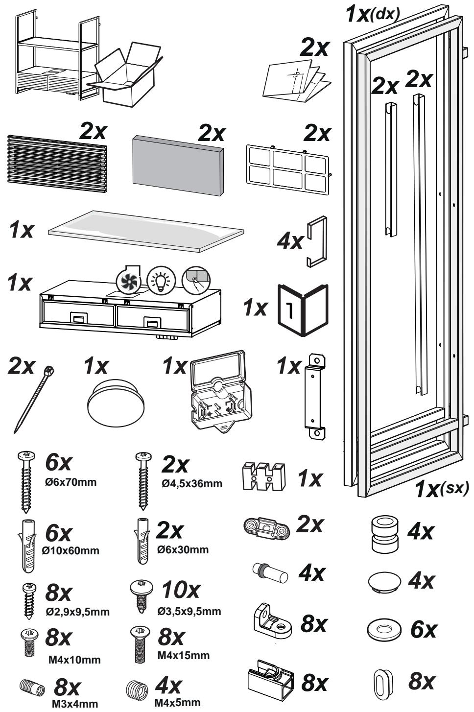
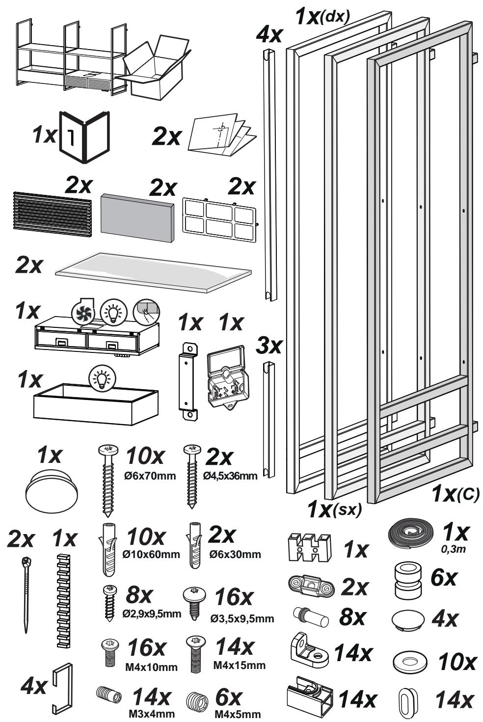
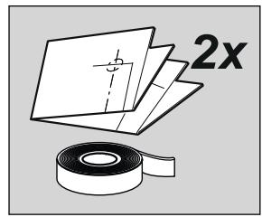
- Check (for transport reasons) that there is no other supplied material inside the hood (e.g. packets with screws (*), guarantees (*), etc.), eventually removing them and keeping them.
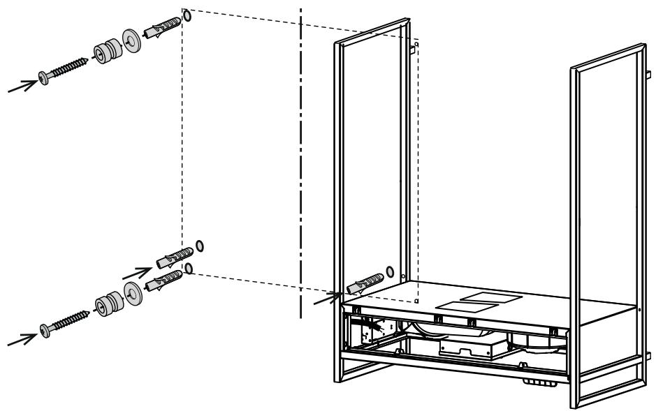
Expansion wall plugs are provided to secure the hood to most types of walls/ceilings. However, a qualified technician must verify suitability of the materials in accordance with the type of wall/ceiling. The wall/ceiling must be strong enough to take the weight of the hood.
Do not tile, grout or silicone this appliance to the wall. Surface mounting only.
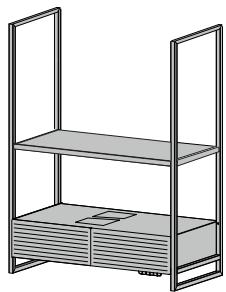
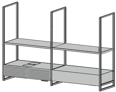
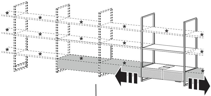
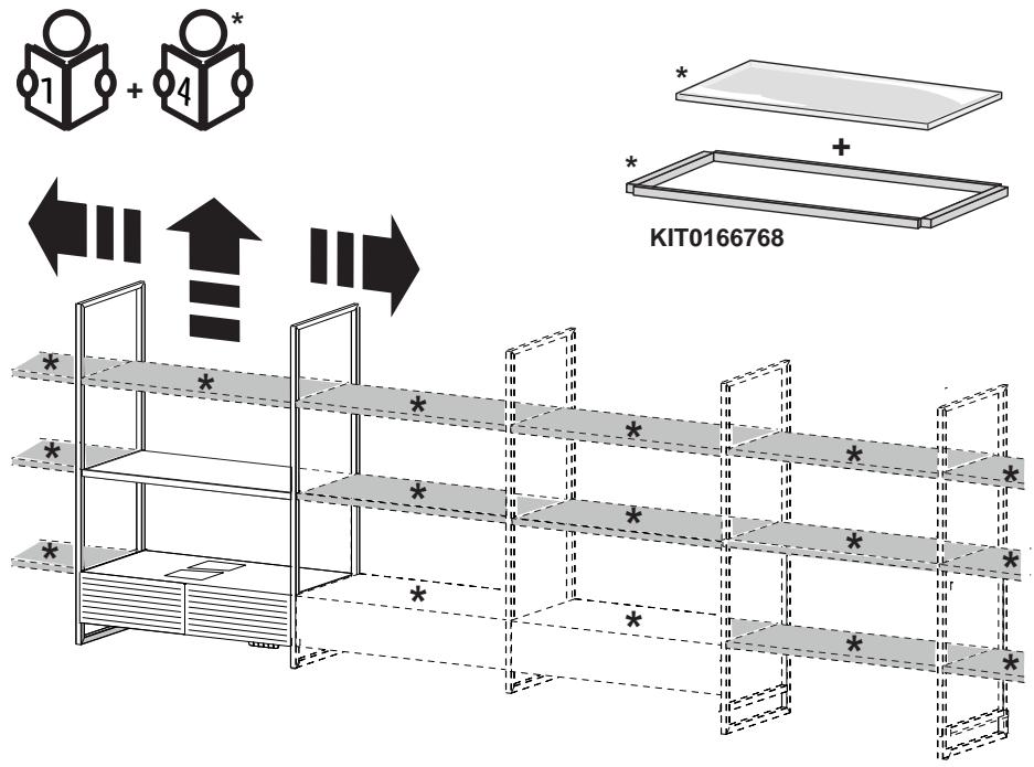
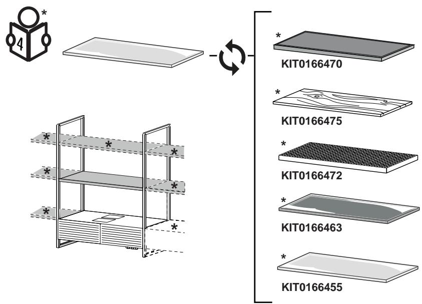
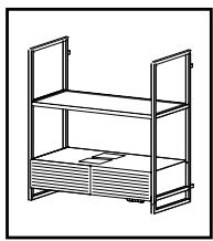
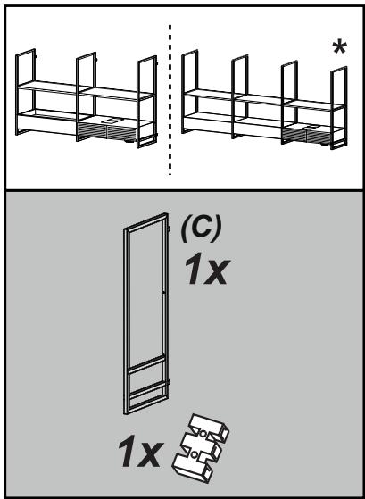
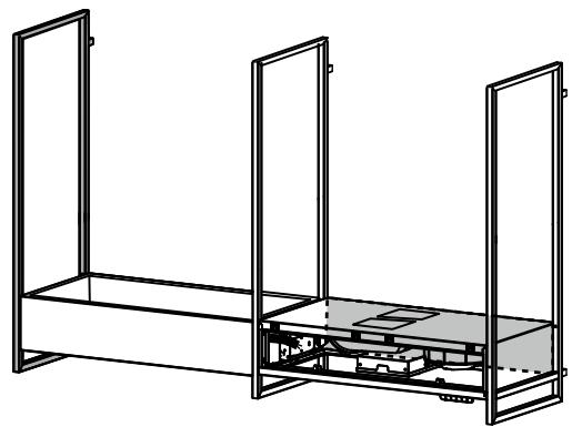
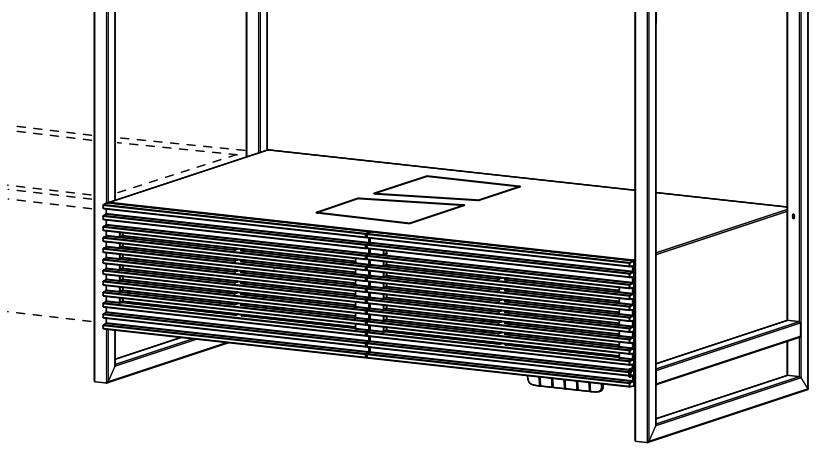
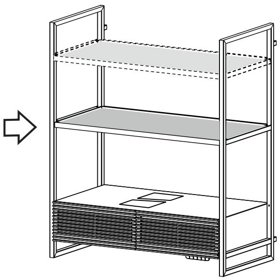
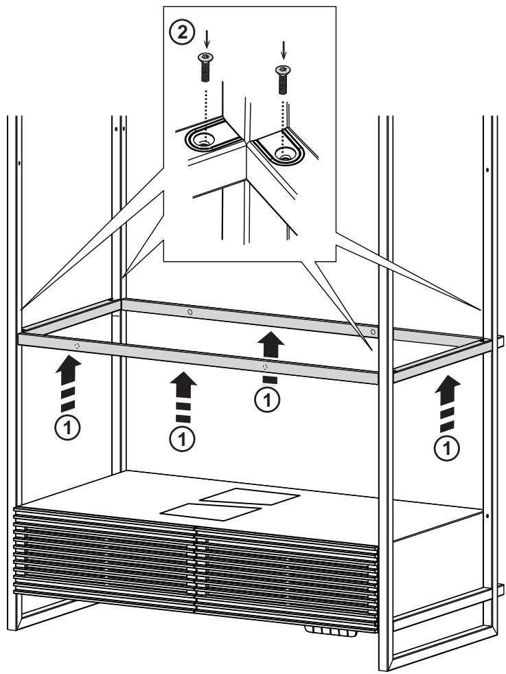
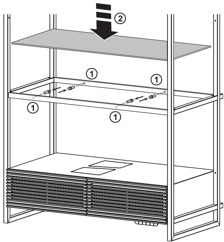
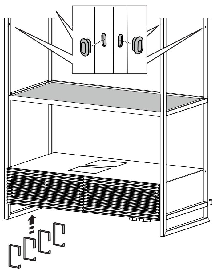
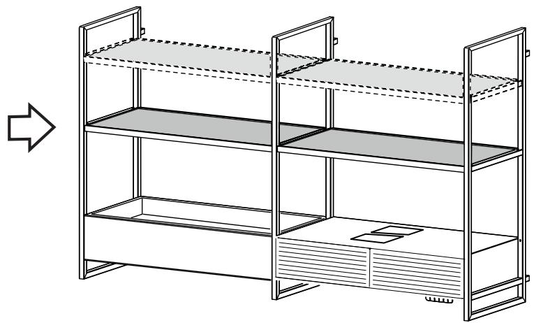
The product can be completed in height with the addition of shelves with frame or extended in width by joining trusses, with additional motor, additional light, shelves with frame.
All these accessories must be purchased separately.
Attention: check that the code of the Motor and additional light kit indicated in this handbook in the illustrations section is the same as that reported in the features label found in the motor and light kit.
Elica Connect
The hood features a WiFi function for remote connection via the Elica Connect app.
Minimum system requirements:
• 2.4GHz WiFi b/g/n wireless router
- Android or iOS Smartphone. Via the stores, check that the app is compatible with the operating system your Smartphone is running.
Note: The ELICA manufacturer declares that this model of household appliance with WiFi module radio equipment complies with Directive 2014/53/EU.
The radio equipment operates within the 2.4GHz ISM frequency band, the maximum radio frequency power transmitted does not exceed 20 dBm (e.i.r.p.).
Warnings:
- Data protection. The data that the connected device detects is collected to allow for all the services of the connected appliance to be used. Further information on how the collected data is processed and on the privacy policy is available at www.elica.com.
• Availability in different countries. The Elica Connect service is available in specific countries. For further information, see the dedicated section at www.elica.com.
- Future changes. Elica reserves the right to make any changes deemed useful to improve the Elica Connect service. As a result, the descriptions contained in this manual are not binding and should be treated as purely indicative.
Operation

- WiFi configuration: if the WiFi function is not configured, press for about 2 seconds to enter WiFi configuration mode and follow the instructions on the App to complete the procedure.
During the configuration procedure, the button will light up indicating the connectivity status (see WiFi status table) To interrupt the WiFi configuration procedure, press for about 2 seconds when the button is lit up and is flashing fast.
Once the WiFi function has been configured, if you want to change it, press for about 6 seconds to reset the WiFi parameters (the button will turn off) and repeat the configuration procedure.
- WiFi activation/deactivation: after the configuration, it is possible to deactivate/activate the WiFi function. Press for about 2 seconds to deactivate/activate the WiFi function.
Deactivating the function does not cause the loss of the WiFi parameters.
WiFi status table
| Keys | Device connection status |
| Low intensity light (all keys) | Wi-Fi active, not connected. |
| White light on steady (Wi-Fi key only) | Wi-Fi active, connected. |
| Orange light flashing fast (Wi-Fi key only) | Wi-Fi active, attempting to connect to Wi-Fi router |
| White light flashing slowly (Wi-Fi key only) | Wi-Fi active, attempting to connect to Elica cloud |
| White light on with short flashing light (Wi-Fi key only) | Wi-Fi active, receiving a remote command (e.g. motor or light power-on) |
note: with Wi-Fi configured, if there is no active function, the intensity of the Wi-Fi key automatically decreases.

Press to turn the cooktop light on or off.
In selected models only:
Intensity regulation: With the light on, press and hold to adjust the light intensity.
Tone regulation: With the light on, press and hold keys ⚙️ and ⚗ to adjust the light tone.

"BOOST" speed selection key
1st press : Push to activate the high speed (suction power)
2nd press: to activate the intensive extraction speed "BOOST" timed for 5 minutes
Note: after the 5 minutes the hood will go back to the previously set extraction speed
3rd press (from "BOOST active): to exit the function and return to the previously set speed.
Note: the speed key previously set remains lit during BOOST operation.

Speed selection key 2
Push to activate the average speed (suction power)

Speed selection key 1
Push to enable the low speed (suction power)

PPower-off key
If pressed while the motor is running, the latter will stop.
Filter Saturation indicator lights
The hood signals at regular intervals that the filters must be serviced.

and III> lit and flashing very slowly: service the se filter.

and III> lit and flashing very quickly: service the odour filter.
Note: The filter saturation warning signal is visible within the first 10 seconds after the hood is switched on.
Reset filter saturation indicator:
Press and hold the keys

The keys will flash quickly—to confirm that reset has been completed
Activation of filter saturation indicators
Note: this operation must be performed with the hood off.
- Grease filter
1st press and holding of keys ⚙️ and ⌘>
the keys light up flashing very slowly, indicating that the grease filter indicator can be activated
Note: Press the "†" button to enable and the "○" button to disable.
- Odour filter
2nd press and holding of keys ⚙️ and ⌘
the keys light up flashing quickly, indicating that the odour filter indicator can be activated (normally deactivated)
Note: Press the "↑" button to enable and the "○" button to disable.
Note: 3rd press and holding of keys ⚙️ and ⌘> to exit settings menu.
Maintenance
Cleaning
Clean using ONLY a cloth dampened with neutral liquid detergent. DO NOT CLEAN WITH TOOLS OR INSTRUMENTS. Do not use abrasive products. DO NOT USE ALCOHOL!
The grille must be washed by hand with hot water and neutral detergent, then dried thoroughly to prevent oxidation.
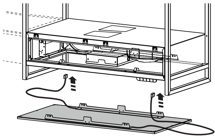
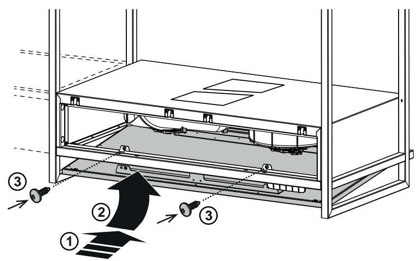
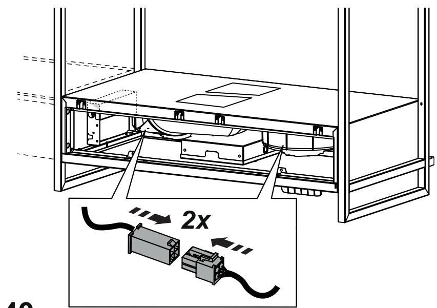
Fig. 43
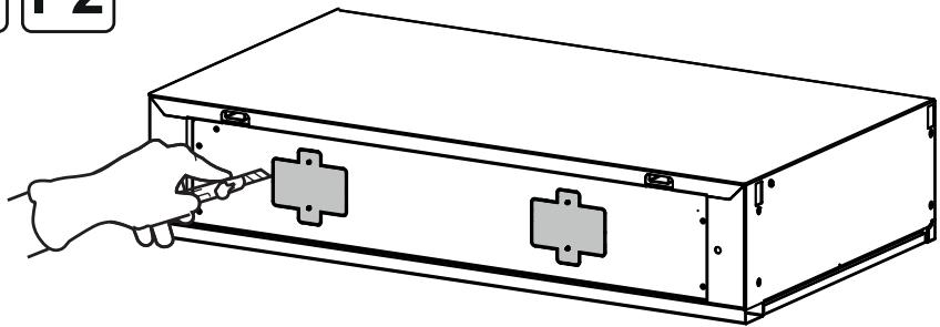
Grease filter
The grease filter must be cleaned once a month using non aggressive detergents, either by hand or in the dishwasher, which must be set to a low temperature and a short cycle. When washed in a dishwasher, the grease filter may discolor slightly, but this does not affect its filtering capacity.
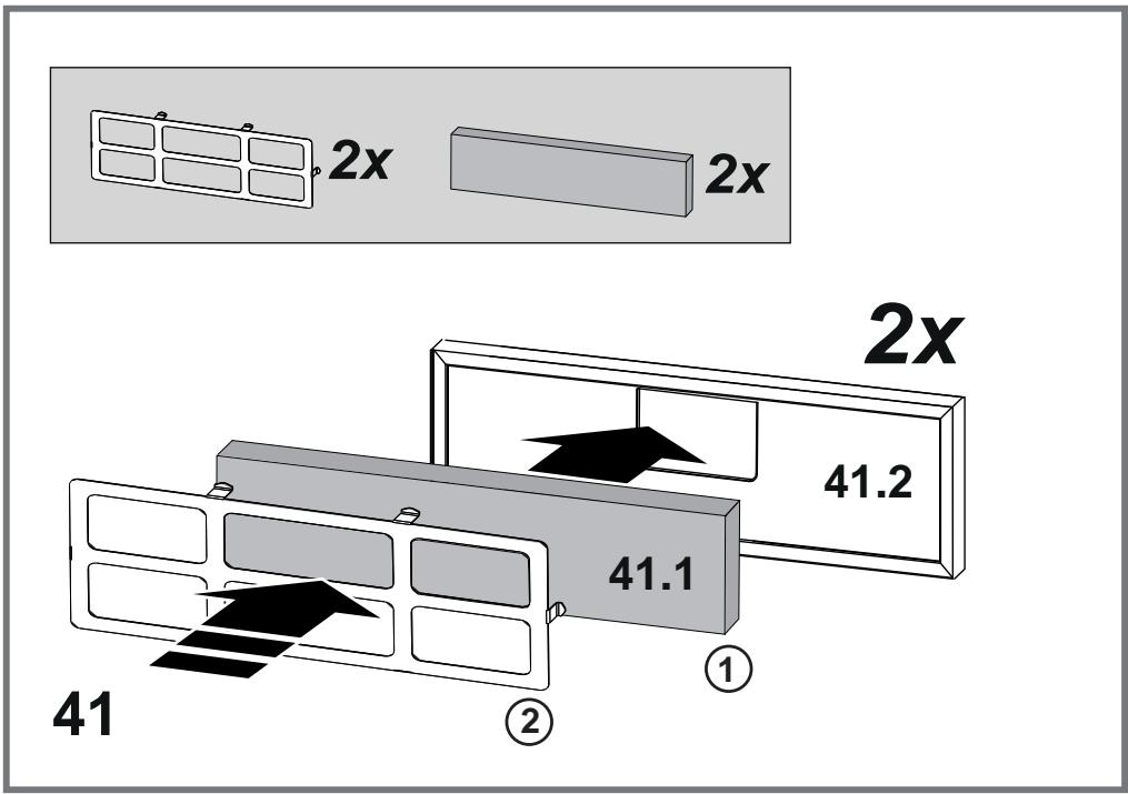
Fig. 41.2
Charcoal filter (filter version only)
It absorbs unpleasant odors caused by cooking.
The charcoal filter can be washed once every two months (or when the filter saturation indication system – if envisaged on the model in possession – indicates this necessity) using hot water and a suitable detergent, or in a dishwasher at 65^ C (if the dishwasher is used, select the full cycle function and leave dishes out).
Eliminate excess water without damaging the filter, then remove the mattress located inside the plastic frame and put it in the oven for 10 minutes at 100^ C to dry completely. Replace the mattress every 3 years and when the cloth is damaged.
Fig. 41.1
Replacing lamps
The hood is equipped with a lighting system based on LED technology.
The LEDs guarantee an optimum lighting, a duration up to 10 times longer than the traditional lamps and allow to save 90% electrical energy.
The lighting system cannot be replaced by the user, contact Customer Service in case of malfunction.
- Waste Electrical and Electronic Equipment (WEEE).