
NUVOLA - Kitchen hood FALMEC - Free user manual and instructions
Find the device manual for free NUVOLA FALMEC in PDF.
| Product type | Kitchen hood (NUVOLA model) |
| Brand | FALMEC |
| Configuration | External ducting (extracting) or internal recirculation (filtering) |
| Minimum distance above a gas hob | 65 cm |
| Main material | Brushed stainless steel |
| Control type | Touch electronic (WZZG) and radio control (433.92 MHz) |
| Number of motor speeds | 4 (the 4th is timed) |
| Lighting | LED, color temperature adjustable from 2700 K to 5600 K |
| Grease metal filters | Washable (recommended every 30 hours of use) |
| Timer function | Automatic motor shutdown after 15 minutes |
| Motor type | Built-in or remote (depending on configuration) |
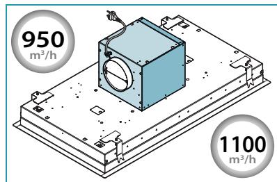
| Non-return flap | Included for flow rate ≥ 800 m³/h |
| Included accessories | Fixing kit, suction hose, cleaning cloths |
| Surface maintenance | Cleaning with Magic Steel cloths or a damp cloth and mild detergent |
| Safety | Disconnect before maintenance; do not use without filters; do not install outdoors |
Frequently Asked Questions - NUVOLA FALMEC
User questions about NUVOLA FALMEC
0 question about this device. Answer the ones you know or ask your own.
Ask a new question about this device
Download the instructions for your Kitchen hood in PDF format for free! Find your manual NUVOLA - FALMEC and take your electronic device back in hand. On this page are published all the documents necessary for the use of your device. NUVOLA by FALMEC.
USER MANUAL NUVOLA FALMEC
natural_image
Exterior view of a modern office building (no signage)Design
Nuvola Led
video
d'installazione
installation
video


INSTRUCTIONS BOOKLET
LIBRETTO ISTRUZIONI ^1T
INSTRUCTIONS BOOKLET EN
EN - Installation with motor on the hood.
natural_image
Isometric technical drawing of a mechanical housing with circular components and mounting brackets (no text or symbols)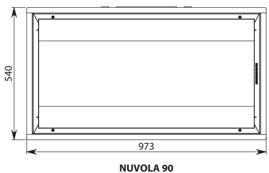
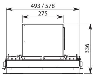
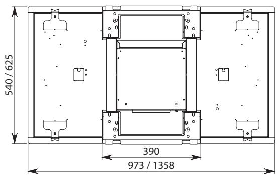
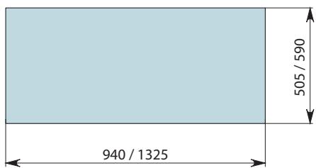
DIMENSIONE FORATURA
HOLE SIZES

NUVOLA LED 90: 37 KG
NUVOLA LED 140: 45 KG
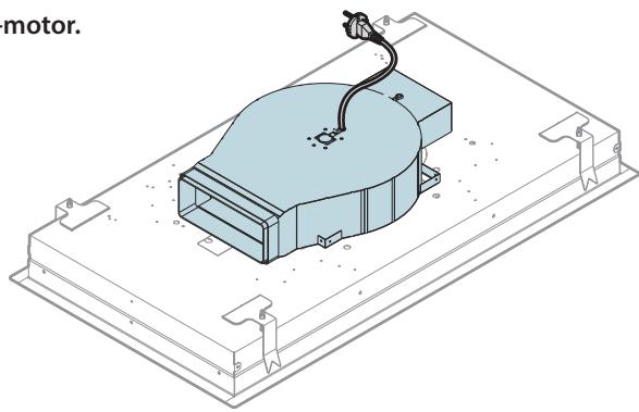
IT - Installazione con motore SLIM.
EN - Installation with SLIM motor.
DE - Installation SLIM-Motor.
FR - Installation avec moteur SLIM.
ES - Instalación con motor SLIM.
RU - Установка с двигателем SLIM.
PL - Instalacja z silnikiem SLIM.
NL - Installatie met SLIM motor.
PT - Instalação com motor SLIM.
DK - Installation med motoren SLIM.
SE - Installation med SLIM-motor.
FI - Asennus SLIM-moottorilla.
NO - Installasjon med SLIM-motor.
pag.
Seite
str.
sivu
page
стр.
side
natural_image
Isometric technical drawing of a motor assembly with housing and mounting brackets (no text or symbols)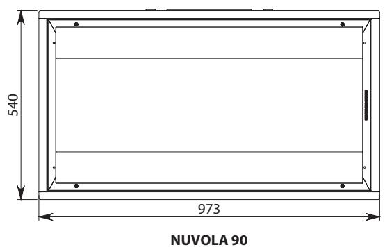
DIMENSIONE FORATURA
HOLE SIZES

NUVOLA LED 90: 29 KG
NUVOLA LED 140: 37 KG
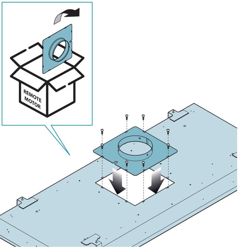
EN - Installation with conveyor kit and remote motor.
EN - Installation with remote motor.
natural_image
Isometric technical drawing of a mechanical housing component with a central circular recess and mounting brackets (no text or symbols)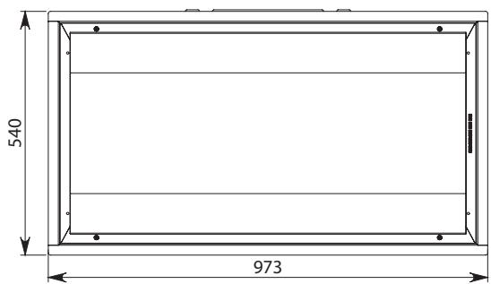
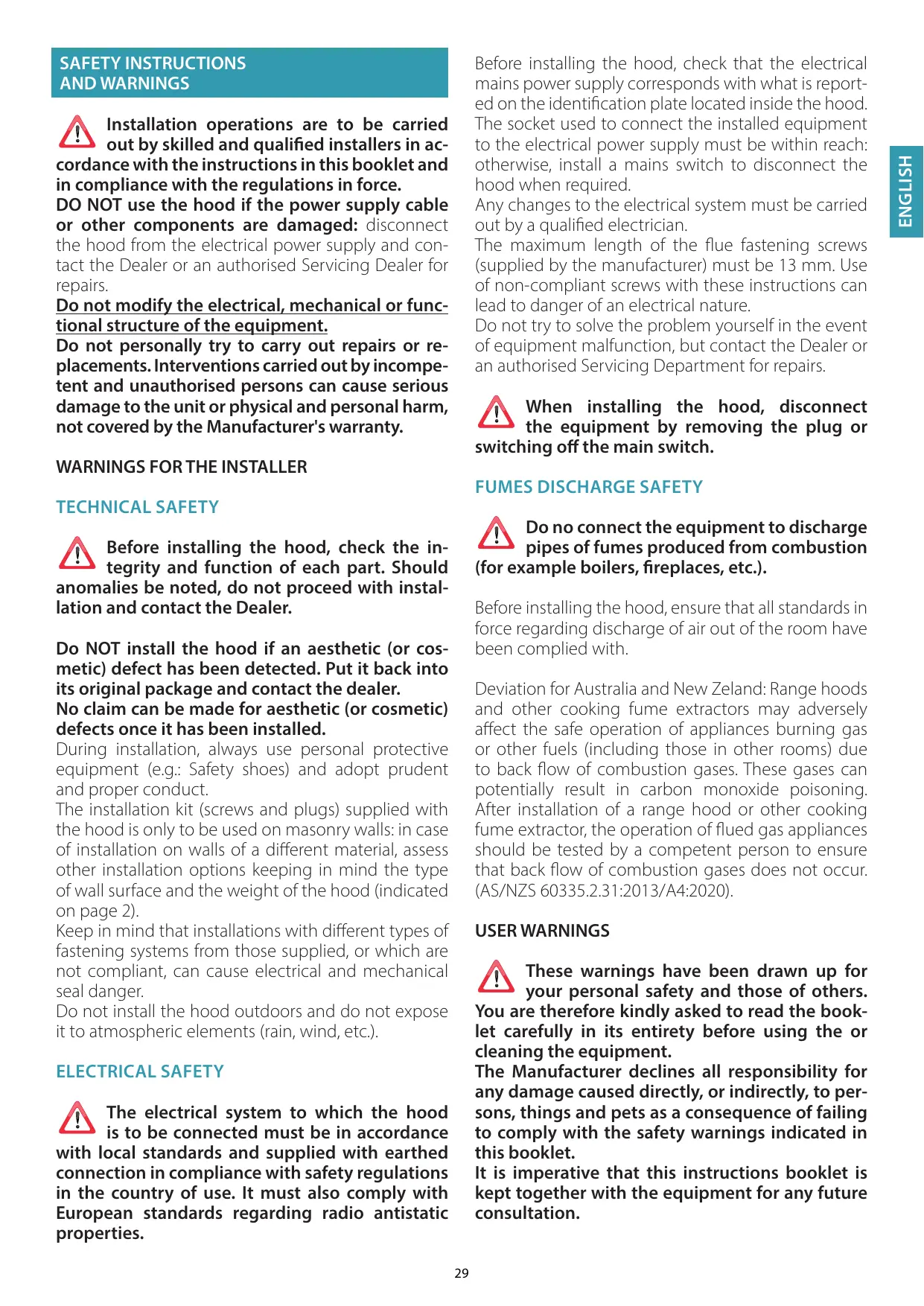
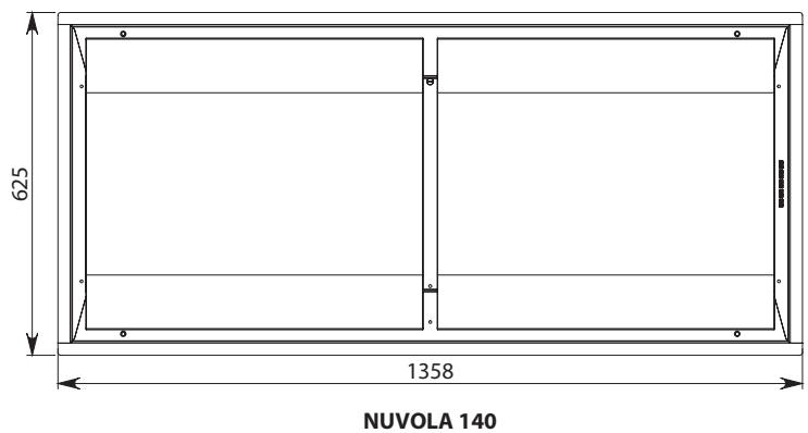
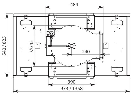
NUVOLA 90
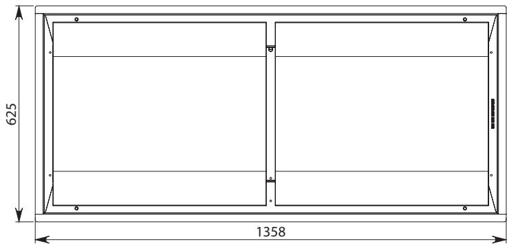
NUVOLA 140
DIMENSIONE FORATURA
HOLE SIZES

NUVOLA 90 LED: 27 KG
NUVOLA 140 LED: 35 KG
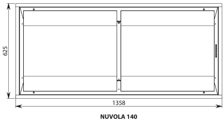
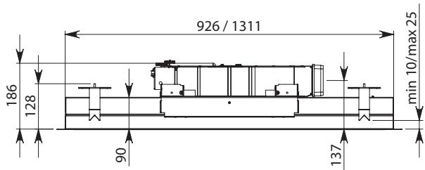
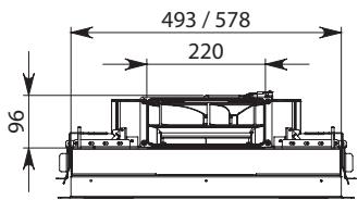
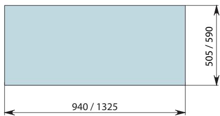
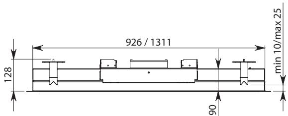
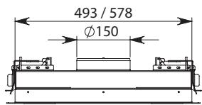
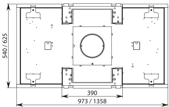
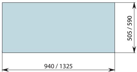
EN - Measurements for installation.
DK - Mal for installation.
SE - Installationsatgarder.
FI - Mitat asennusta varten.
natural_image
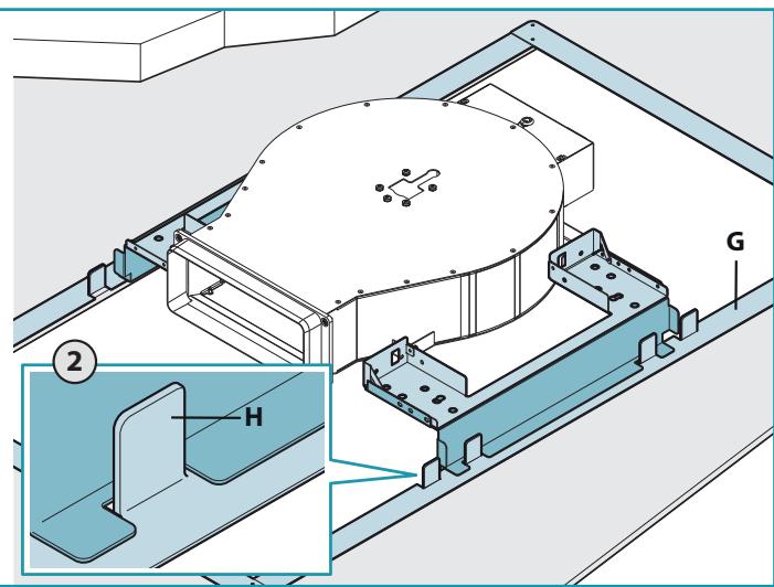
Illustration of various household cleaning and repair tools including ladder, tool, power tool, saw, gloves, and hard hat (no text or symbols present)EN - Preliminary operations: Cutting the plasterboard (1), inserting the supporting frame (2).
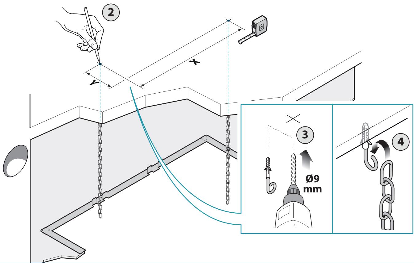
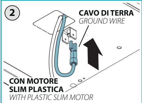
EN - Preliminary operations: fixing the mandatory safety chains to the ceiling.
| NUVOLA | 90 | 140 |
| X | 520 mm | 940 mm |
| Y | 266 mm | 266 mm |
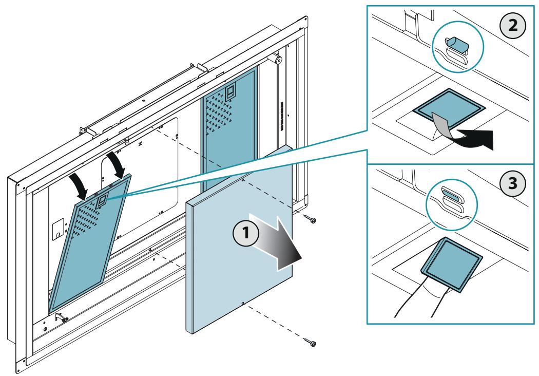
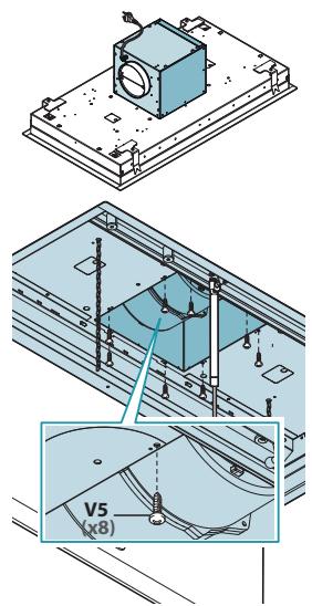
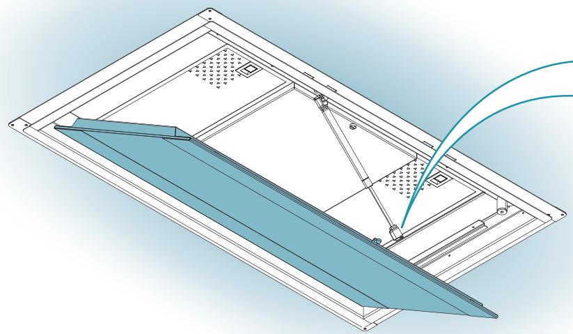
EN - Open the panel, remove the gas piston (4) and filters (5).
5
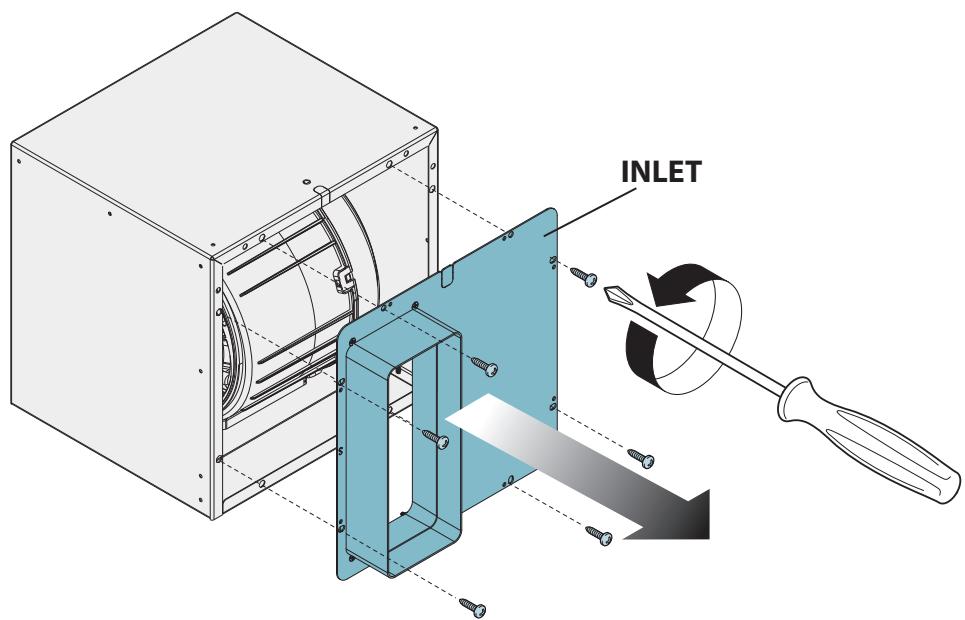
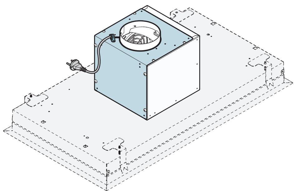
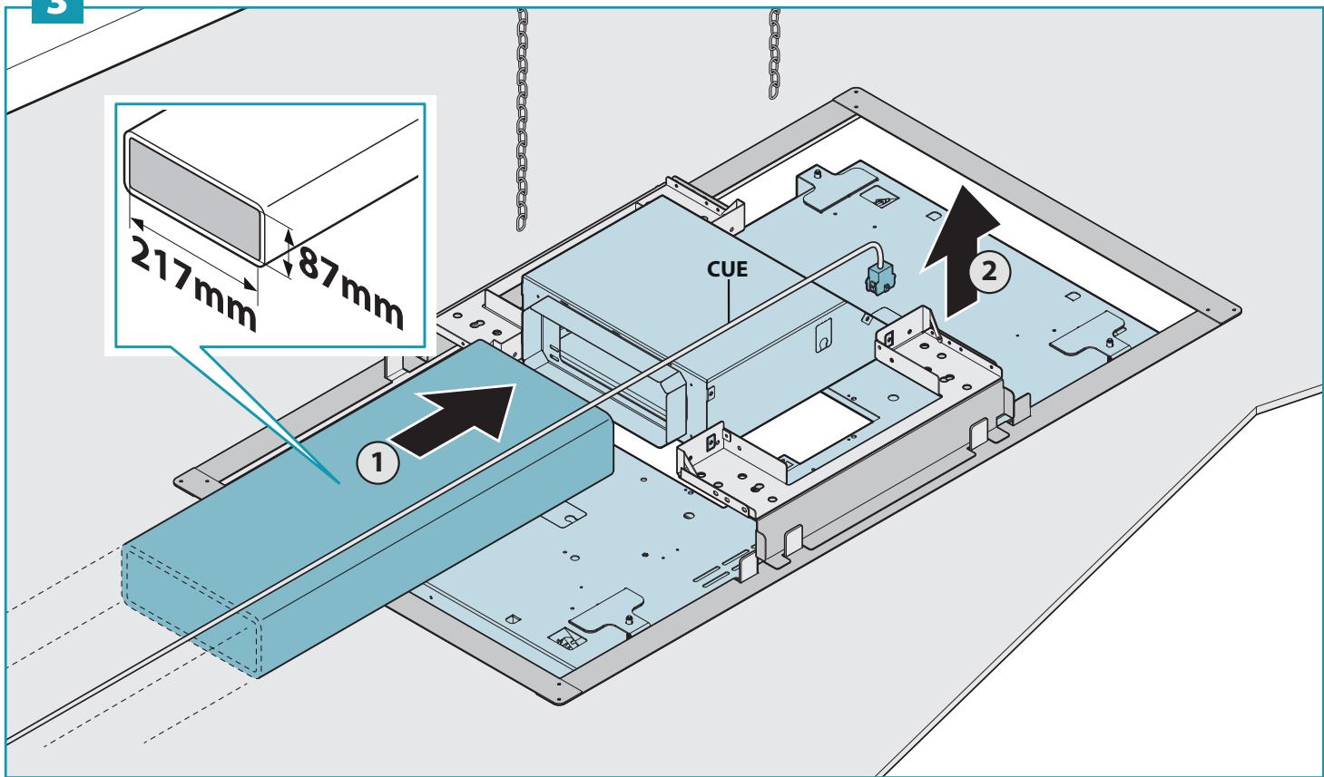
IT - Togliere la flangia dal motore (1). Se l'uscita aria è verso l'alto, vedi (2). Per altre direzioni, Vedere (3) e (4).
EN - Remove the flange from the motor (1). If the air outlet is upward, see (2). For other directions, see (3) and (4).
DE - Den Flansch entfernen des Motors (1) entfernen. Wenn der Luftauslass nach oben gerichtet ist, siehe (2). Für andere Richtungen siehe (3) und (4).
FR - Retirer la bride du moteur (1). Si la sortie d'air est vers le haut, voir (2). Pour d'autres directions, voir (3) et (4).
ES - Retirar la brida del motor (1). Si la salida de aire es ascendente, véase (2). Para otras direcciones, ver (3) y (4).
RU - Снимите фланец двигателя (1). Если выпускное отверстие воздуха вверх, см (2). Для других направлений, см (3) и (4).
PL - Zdjąć kołnierz z silnika (1). Jeżeli wylot powietrza do góry, patrz (2). PW przypadku innych kierunków, patrz (3) i (4).
NL - Verwijder de flens van de motor (1). Of de luchtuitlaat is opwaarts, zie (2). Voor andere richtingen, zie (3) en (4).
PT - Retirar o flange do motor (1). Se a saída de ar é para cima, ver (2). Para outras indicações, ver (3) e (4).
DK - Tag flangen af motoren (1). Hvis afgangsluften er opad, se (2). For andre retninger, se (3) og (4).
SE - Avlägsna flänset motor (1). Om luftutloppet är uppåt, se (2). För andra riktningar, se (3) och (4).
FI - Ota laippa pois ja moottorista (1). Jos ilmanpoistoaukko on ylöspäin (2). Ja muihin suuntiin, katso (3) ja (4).
NO - Fjern flensen motoren (1).
Dersom luftutløpet er oppover, se (2). For andre retninger, se (3) og (4).
1
2
natural_image
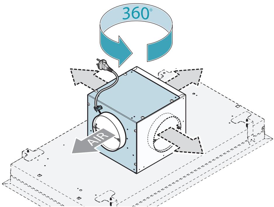
Technical line drawing of a mechanical assembly with a central box and wiring, mounted on a rectangular base (no text or symbols)EN - Side movement of the air exhaust
natural_image
Technical illustration of a mechanical device with internal components and a labeled section (5), no readable text or symbols present.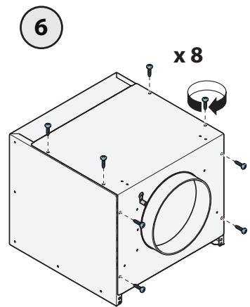
4
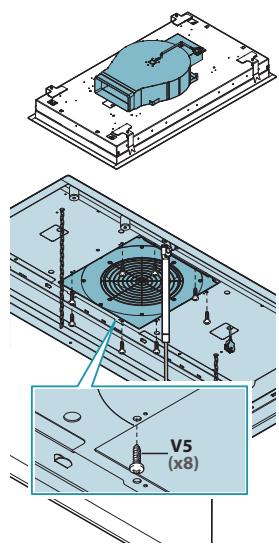
EN - Fixing the motor support brackets (5).
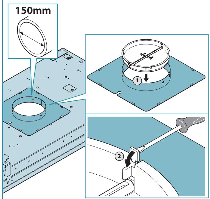
EN - Fitting the non-return valve (6). Positioning the motor on the support frame (7).
natural_image
Technical line drawing of a mechanical assembly with a circular component and mounting base (no text or symbols)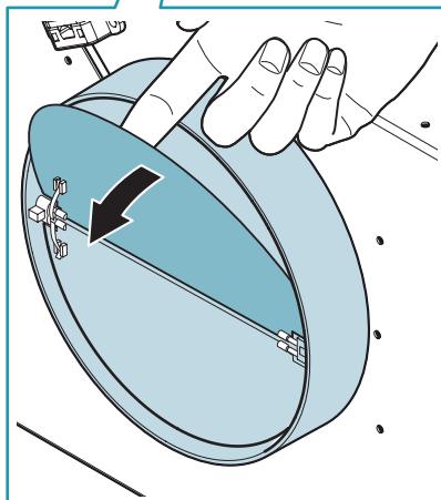
natural_image
Illustration of a hand holding a circular mechanical component with a black arrow indicating rotation (no text or symbols)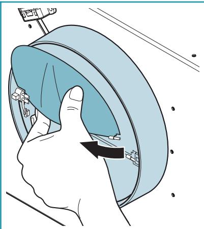
natural_image
Illustration of a hand pressing down on a blue mechanical component with directional arrows (no text or symbols)7
natural_image
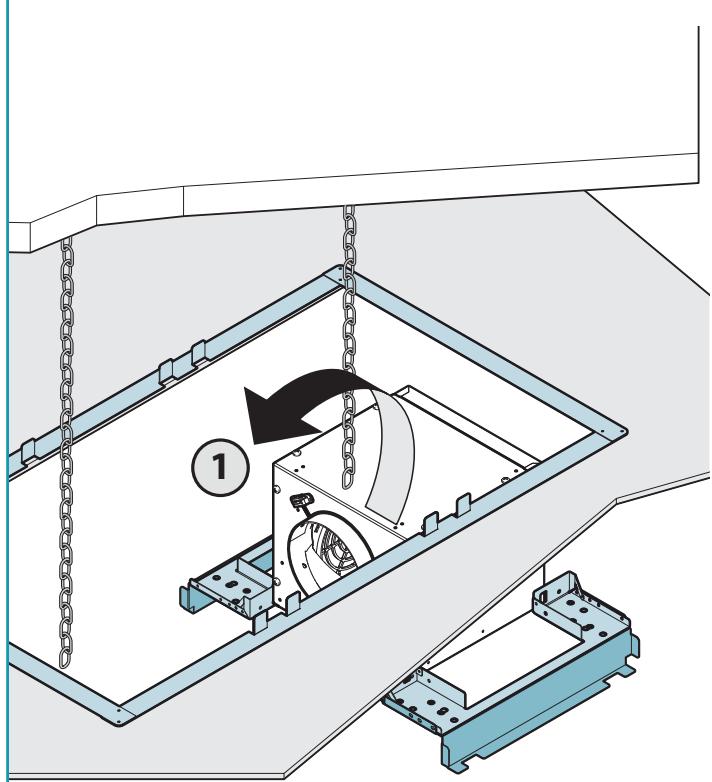
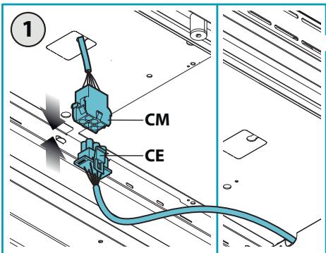
Technical illustration of a mechanical assembly with chains and a central fan component (no text or symbols)EN - Fitting the suction pipe and electrical connection (8).
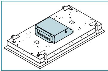
EN - Fixing the motor support brackets (1).
natural_image
Isometric technical drawing of a mechanical component with mounting base and housing (no text or symbols)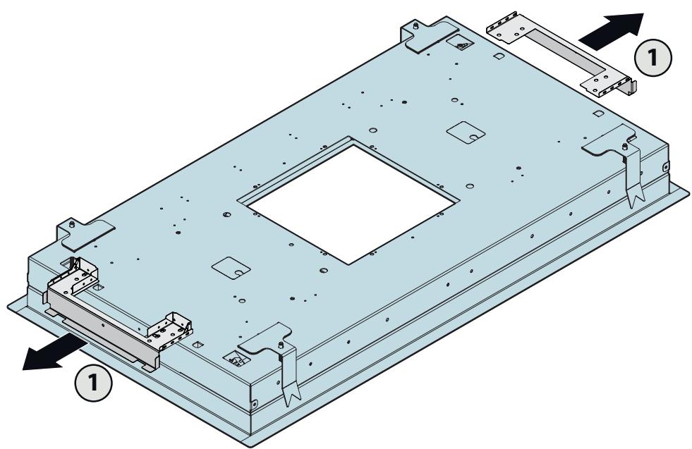
natural_image
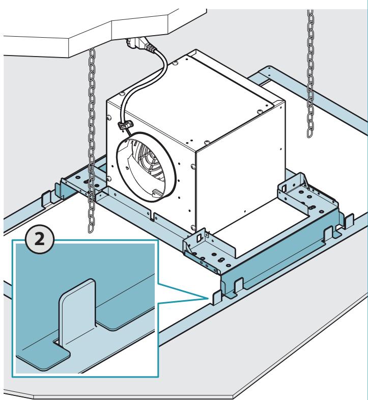
Technical diagram of a rectangular electronic component with mounting brackets and internal cavity (no text or symbols)1
EN - Positioning the motor on the support frame (2). Fitting the suction pipe (3).
3
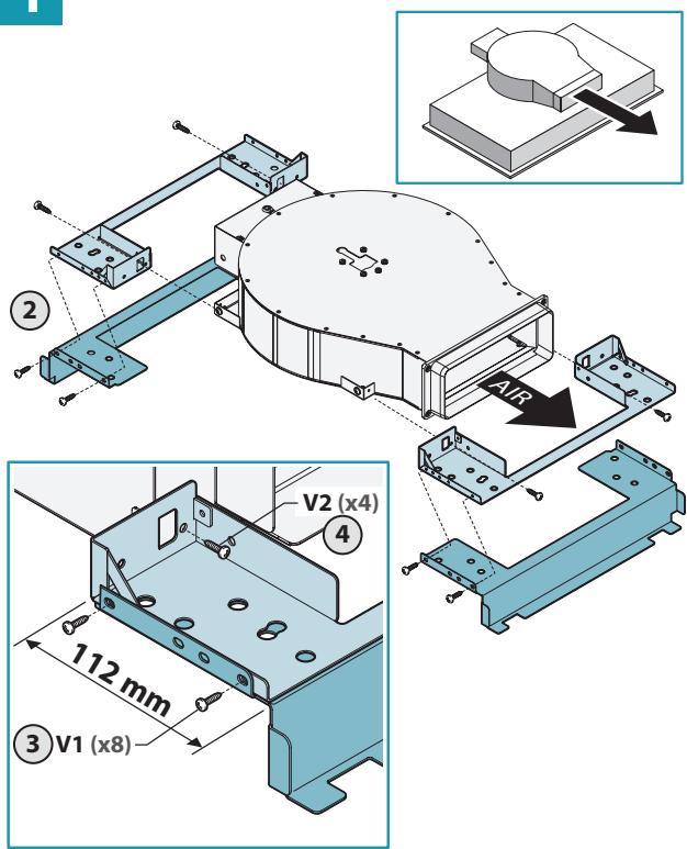
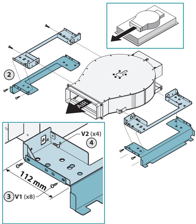
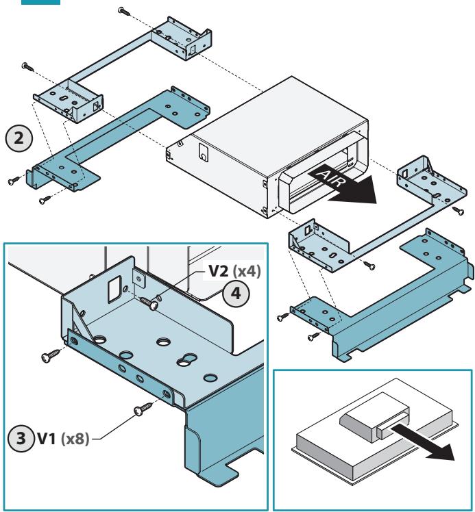
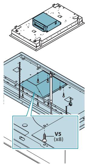
IT - Fissaggio staffe su raccordo rettangolare (1).
EN - Fixing the brackets onto the rectangular connection (1).
DE - Befestigung Bügel am rechteckigem Anschluss (1).
FR - Fixation des étriers sur raccord rectangulaire (1).
ES - Fijación de las bridas en el accesorio rectangular (1).
RU - Крепление кронштейнов на прямоугольном патрубке (1).
PL - Mocowanie wsporników na elemencie prostokątnym (1).
NL - Bevestiging beugels op rechthoekige aansluiting (1).
PT - Fixação das braçadeiras em conector retangular (1).
DK - Fastspænding af konsoller på det rektangulære samlestykke (1).
SE - Fäst konsolerna på den rektangulära kopplingen (1).
FI - Kannattimien kiinnitys suorakulmaiseen liitokseen (1).
NO - Plassering av stengene på den rektangulære koblingen (1).
natural_image
Isometric technical drawing of a rectangular electronic component with mounting brackets and a central housing (no text or symbols)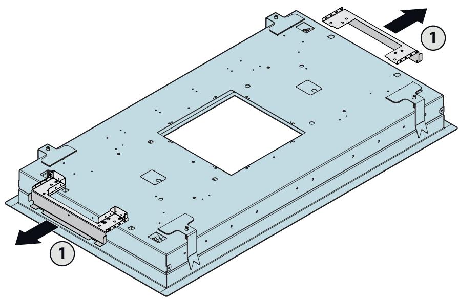
natural_image
Technical diagram of a rectangular electronic device with mounting brackets and internal cavity (no text or symbols)1
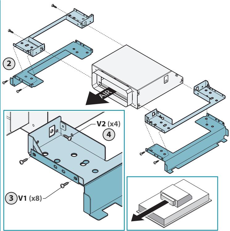
EN - Positioning the rectangular connection on the support frame (2). Fitting the suction pipe (3).
3
EN - Fitting the non-return valve.
natural_image
Isometric technical drawing of a mechanical housing component with a central circular recess (no text or symbols)1
2
3
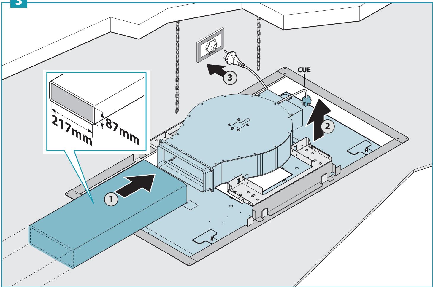
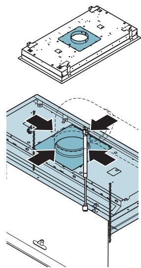
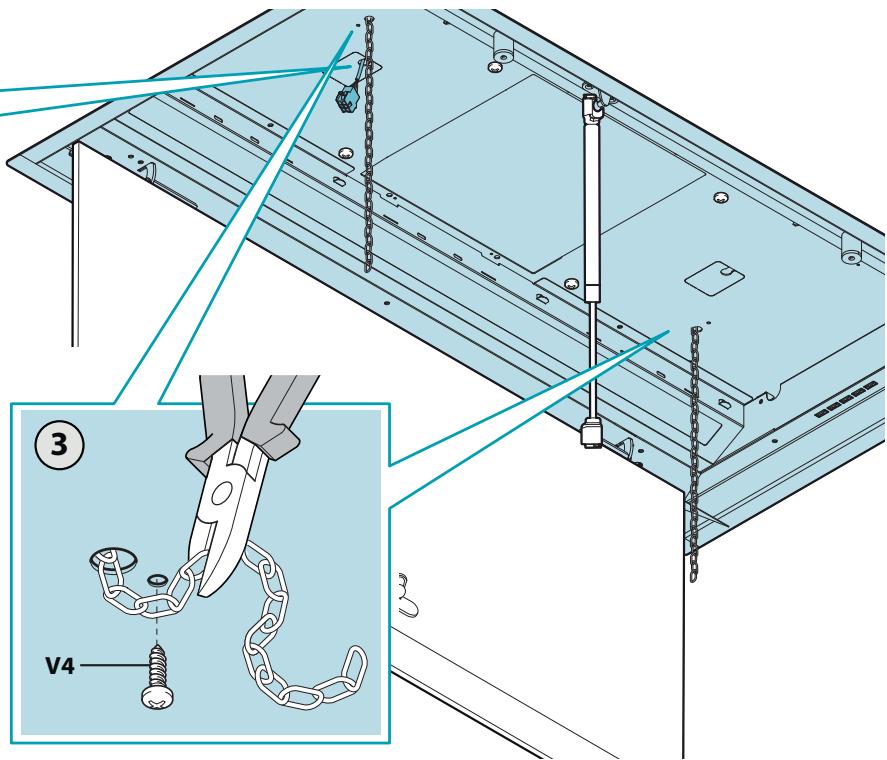
EN - Final operations:
Passing the chains through, passing the control cable through.
natural_image
Technical diagram showing a mechanical assembly with chains and a lock, no visible text or symbols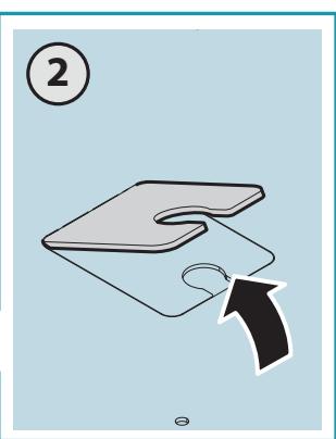
natural_image
Illustration of a folded paper or plastic sheet with an arrow indicating direction (no text or symbols)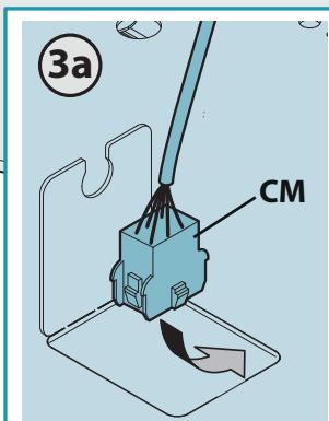
CON MOTORE REMOTO
WITH REMOTE MOTOR
CON MOTORE SLIM PLASTICA
WITH PLASTIC SLIM MOTOR
EN - Closing the holding brackets.
natural_image
Technical line drawing of a mechanical assembly with mounting brackets and internal components (no text or symbols)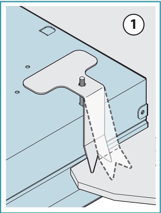
natural_image
Technical diagram of a mechanical clamp or bracket assembly with dashed lines indicating internal components (no text or symbols present)2
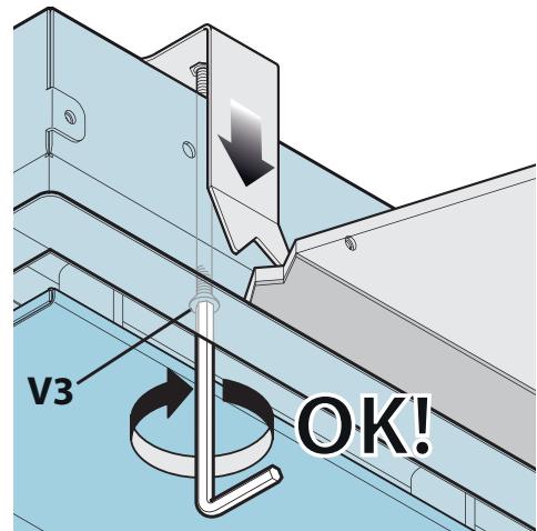
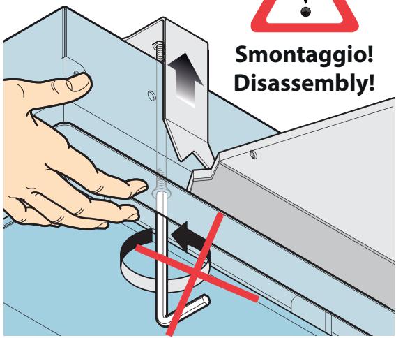
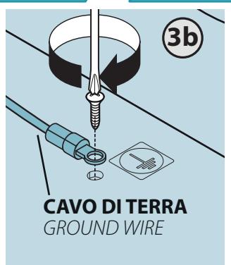
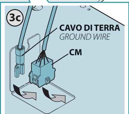
IT - Fissaggio motore (o raccordo rettangolare) (3), collegamento elettrico e tensionamento catenelle di sicurezza (4).
EN - Fixing the motor (or rectangular connection) (3), electrical connection and tensioning the safety chains (4).
DE - Befestigung Motor (oder rechteckiger Anschluss) (3), elektrischer Anschluss und Spannen Sicherungsketten (4).
FR - Fixation du moteur (ou raccord rectangulaire) (3), raccordement électrique et tension des chaînes de sécurité (4).
ES - Fijación del motor (o accesorio rectangular) (3), conexión eléctrica y tensado de las cadenas de seguridad (4).
RU - Крепление двигателя (или прямоугольного патрубка) (3), подключение к электросети и натяжение предохранительных цепочек (4).
PL - Mocowanie silnika (lub elementu prostokątnego) (3), połączenie elektryczne i naprężenie łańcuchów zabezpieczających (4).
NL - Bevestiging motor (of rechthoekige aansluiting) (3), elektrische aansluiting of aanspannen veiligheidskettingen (4).
PT - Fixação do motor (ou conector retangular) (3), ligação elétrica e esticamento das correntes de segurança (4).
DK - Fastspænding af motor (eller rektangulært samlestykke) (3), elektrisk tilslutning og spænding af sikkerhedskæder (4).
SE - Fäst motorn (eller den rektangulära kopplingen) (3), anslut elen och spänn säkerhetskedjorna (4).
FI - Moottorin kiinnitys (tai suorakulmainen liitos) (3), sähköliitäntä ja turvaketjujen kiristys (4).
NO - Feste av motor (eller rektangulær kobling) (3), elektrisk kobling og stramming av sikkerhetskjeder (4).
3
natural_image
Technical diagram showing two views of a mechanical assembly with no visible text or symbols4
5
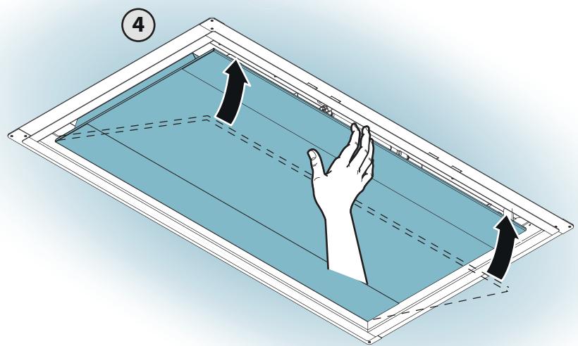
IT - Riposizionamento filtri, pistone e chiusura cappa.
EN - Repositioning filters and piston and closing the hood.
DE - Wiedereinsetzen Filter, Kolben und Verschluss Haube.
FR - Repositionnement des filtres, piston et fermeture de la hotte.
ES - Reposicionamiento de filtros, pistón y cierre de la campana.
RU - Установка на место фильтров, поршня и закрытие вытяжки.
PL - Założenie filtrów, tłoka i zamknięcie okapu.
NL - Filters en zuiger terugplaatsen en kap sluiten.
PT - Reposicionamento dos filtros, pistão e fecho da capa.
DK - Placering af filtre, stempel og emhættens lukning.
SE - Sätt tillbaka filtren, kolven och stäng fläkthuven.
FI - Suodattimien ja männän asemointi takaisin ja liesituulettimen sulku.
NO - Ny plassering av filter, stempel og lukking av hette.
natural_image
Technical line drawing of a mechanical assembly with a blue panel and internal components (no text or symbols)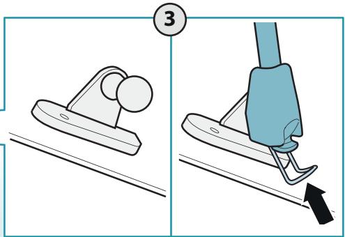
natural_image
Diagram showing a hand pressing down on a blue panel with dashed lines indicating movement, no text or symbols present.
AVVERTENZE!:
SAFETY INSTRUCTIONS AND WARNINGS
Installation operations are to be carried out by skilled and qualified installers in accordance with the instructions in this booklet and in compliance with the regulations in force.
DO NOT use the hood if the power supply cable or other components are damaged: disconnect the hood from the electrical power supply and contact the Dealer or an authorised Servicing Dealer for repairs.
Do not modify the electrical, mechanical or functional structure of the equipment.
Do not personally try to carry out repairs or replacements. Interventions carried out by incompetent and unauthorised persons can cause serious damage to the unit or physical and personal harm, not covered by the Manufacturer's warranty.
WARNINGS FOR THE INSTALLER
TECHNICAL SAFETY
Before installing the hood, check the integrity and function of each part. Should anomalies be noted, do not proceed with installation and contact the Dealer.
Do NOT install the hood if an aesthetic (or cosmetic) defect has been detected. Put it back into its original package and contact the dealer.
No claim can be made for aesthetic (or cosmetic) defects once it has been installed.
During installation, always use personal protective equipment (e.g.: Safety shoes) and adopt prudent and proper conduct.
The installation kit (screws and plugs) supplied with the hood is only to be used on masonry walls: in case of installation on walls of a different material, assess other installation options keeping in mind the type of wall surface and the weight of the hood (indicated on page 2).
Keep in mind that installations with different types of fastening systems from those supplied, or which are not compliant, can cause electrical and mechanical seal danger.
Do not install the hood outdoors and do not expose it to atmospheric elements (rain, wind, etc.).
ELECTRICAL SAFETY
The electrical system to which the hood is to be connected must be in accordance with local standards and supplied with earthed connection in compliance with safety regulations in the country of use. It must also comply with European standards regarding radio antistatic properties.
Before installing the hood, check that the electrical mains power supply corresponds with what is reported on the identification plate located inside the hood. The socket used to connect the installed equipment to the electrical power supply must be within reach: otherwise, install a mains switch to disconnect the hood when required.
Any changes to the electrical system must be carried out by a qualified electrician.
The maximum length of the flue fastening screws (supplied by the manufacturer) must be 13 mm. Use of non-compliant screws with these instructions can lead to danger of an electrical nature.
Do not try to solve the problem yourself in the event of equipment malfunction, but contact the Dealer or an authorised Servicing Department for repairs.
When installing the hood, disconnect the equipment by removing the plug or switching off the main switch.
FUMES DISCHARGE SAFETY
Do no connect the equipment to discharge pipes of fumes produced from combustion (for example boilers, fireplaces, etc.).
Before installing the hood, ensure that all standards in force regarding discharge of air out of the room have been complied with.
Deviation for Australia and New Zealand: Range hoods and other cooking fume extractors may adversely affect the safe operation of appliances burning gas or other fuels (including those in other rooms) due to back flow of combustion gases. These gases can potentially result in carbon monoxide poisoning. After installation of a range hood or other cooking fume extractor, the operation of flued gas appliances should be tested by a competent person to ensure that back flow of combustion gases does not occur. (AS/NZS 60335.2.31:2013/A4:2020).
USER WARNINGS
These warnings have been drawn up for your personal safety and those of others. You are therefore kindly asked to read the booklet carefully in its entirety before using the or cleaning the equipment.
The Manufacturer declines all responsibility for any damage caused directly, or indirectly, to persons, things and pets as a consequence of failing to comply with the safety warnings indicated in this booklet.
It is imperative that this instructions booklet is kept together with the equipment for any future consultation.
If the equipment is sold or transferred to another person, make sure that the booklet is also supplied so that the new user can be made aware of the hood's operation and relative warnings.
After the stainless steel hood has been installed, it will need to be cleaned to remove any residues remaining from the protection adhesive as well as any grease and oil stains which, if not removed, can cause irreversible damage to the hood surface. To properly clean the unit, the manufacturer recommends using the supplied moist wipes, which are also available sold separately.
Insist on original spare parts.
INTENDED USE
The equipment is solely intended to be used to extract fumes generated from cooking food in non-professional domestic kitchens: any other use is improper. Improper use can cause damage to persons, things, pets and exempts the Manufacturer from any liability.
The equipment can be used by children over the age of 8 and by persons with reduced physical, sensory and mental abilities, or with no experience or knowledge, as long as they do so under supervision or after having received relative instructions regarding safe use of the equipment and understanding of the dangers connected to it.
Children are not to play with the equipment. Cleaning and maintenance by the user must not be carried out by children without supervision.
USE AND CLEANING WARNINGS
Before cleaning or carrying out maintenance operations, disconnect the equipment by removing the plug or switching off the main switch.
Do not use the hood with wet hands or bare feet.
Always check that all electrical parts (lights, extractor fan) are off when the equipment is not being used.
The maximum overall weight of any objects placed or hung (if applicable) on the hood must not exceed 1.5 Kg.
Always supervise the cooking process during the use of deep-fryers: Overheated oil can catch fire.
Do not leave open, unattended flames under the hood.
Do not prepare food over an open flame under the hood.
Never use the hood without the metal anti-grease filters: in this case, grease and dirt will deposit in the equipment and compromise its operation.
Accessible parts of the hood can be hot when used at the same time as the cooking appliances.
Do not carry out any cleaning operations when parts of the hood are still hot.
There can be a risk of fire if cleaning is not carried out according to the instructions and products indicated in this booklet.
Disconnect the main switch when the equipment is not used for long periods of time.
If other appliances that use gas or other fuels are being used at the same time (boiler, stove, fireplaces, etc.), make sure the room where the fumes are discharged is well-ventilated, in compliance with the local regulations.
INSTALLATION
only intended for qualified personnel

Before installing the hood, carefully read the chapter 'SAFETY INSTRUCTIONS AND WARNINGS'.
TECHNICAL FEATURES
The technical specifications are exhibited on the labels located inside the hood.
POSITIONING
The minimum distance between the highest part of the cooking equipment and the lowest part of the hood is indicated in the installation instructions.
Generally, when the hood is placed over gas cookers, the distance must be at least 65 cm (25.6"). However, according to standard EN60335-2-31, the minimum distance between the cooker and lower part of the hood can be reduced to the quota reported in the installation instructions.
Should the instructions for the gas cooker specify a greater distance, this must be taken into consideration.
Do not install the hood outdoors and do not expose it to outdoor environment (rain, wind, etc.).
ELECTRICAL CONNECTION
(only intended for qualified personnel)
Disconnect the equipment from electrical mains power supply before carrying out any operations on the hood.
Ensure that the wires inside the hood are not disconnected or cut: in the event of damage, contact your nearest Servicing Department. Refer to qualified personnel for electrical connections.
Connection must be carried out in compliance with the provisions of law in force.
Before connecting the hood to the electrical mains power supply, check that:
- voltage supply corresponds with what is reported on the data plate located inside the hood;
- the electrical system is compliant and can withstand the load (see the technical specifications located inside the hood);
- the power supply plug and cable do not come into contact with temperatures exceeding 70 °C;
- the power supply system is effectively and properly connected to earth in compliance with regulations in force;
- the socket used to connect the hood is within reach. In case of:
- devices fitted with cables without a plug: the type of plug to use is a "standardised" one. The wires must be connected as follows: yellow-green for earthing, blue for neutral and brown for the phase. The plug must be connected to an adequate safety socket.
- fixed equipment not provided with a power supply cable and plug, or any other device that ensures disconnection from the electrical mains, with an opening gap of the contacts that enables total disconnection in overvoltage category III conditions.
Said disconnection devices must be provided in the mains power supply in compliance with installation regulations.
The yellow/green earth cable must not be cut off by the switch.
The Manufacturer declines all responsibility for failure to comply with the safety regulations.
FUMES DISCHARGE
EXTERNAL EXHAUST HOOD (SUCTION)

In this version the fumes and vapours are discharged outside through the exhaust pipe. To this end, the hood outlet fitting must be connected via a pipe, to an external output.
The outlet pipe must have:
• a diameter not less than that of the hood fitting.
- a slight slope downwards (drop) in the horizontal sections to prevent condensation from flowing back into the motor.
• the minimum required number of bends.
- the minimum required length to avoid vibrations and reduce the suction performance of the hood.
You are required to insulate the pipes if it passes through cold environments. In the presence of motors with 800m^3/h or higher, a check valve is present to prevent external air flowing back.
Deviation for Germany:
when the kitchen hood is used at the same time as appliances that are powered by energy other than electricity, the negative pressure in the room must not exceed 4 Pa (4 x 10⁻⁵ bar).
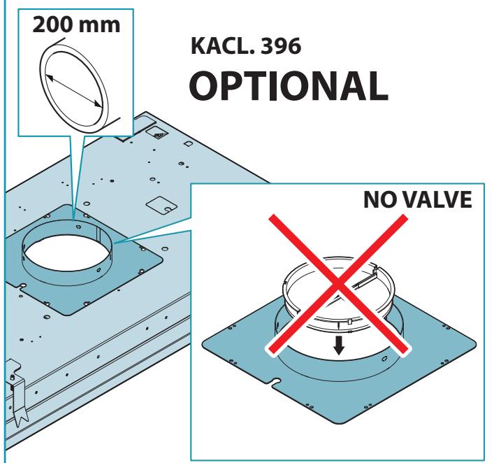
HOOD WITH INTERNAL RECIRCULATION (FILTERING)

In this model, the air passes through an optional filter unit in the ceiling to be purified and recycled in the environment.

In this version the check valve must not be assembled: remove it if it is on the air outlet fitting of the motor.
ASSEMBLY INSTRUCTIONS
only intended for qualified personnel

The hood can be installed in various configurations. The generic assembly steps apply to all installations; for each case, follow the specific steps provided for the required installation.
OPERATION
WHEN TO TURN ON THE HOOD?
Switch on the hood at least one minute before starting to cook to direct fumes and vapours towards the suction surface.
After cooking, leave the hood operating until complete extraction of all vapours and odours. By means of the Timer function, it is possible to set auto switch-off function which will allow the hood to turn off automatically after 15 minutes of operation.
WHICH SPEED IS TO BE SELECTED?
1st speed: maintains the circulation of clean air with low electricity consumption.
2nd speed: normal conditions of use.
3rd speed: presence of strong odours and vapours.
4th speed: rapid disposal of odours and vapours.
WHEN SHOULD THE FILTERS BE WASHED OR REPLACED?
The metal filters must be cleaned every 30 hours of operation.
For further details see the "MAINTENANCE" chap.
ELECTRONIC PUSHBUTTON PANEL
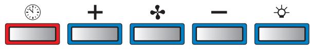
 | Motor ON/OFFMotor OFFLong impulse: change light tone from 2700K to 5600K | |
| [32ST] | Increase speed from 1 to 4Speed 4 is only active for a few minutes, then speed 3 activates. | The speeds are indicated by the LEDs on the keys:+ + -Speed 1+ + -Speed 2+ + -Speed 3+ + -Speed 4("+" LED flashing) |
| [KBTC] | Reduce speed from 4 to 1 | |
| [50SH] | Light on/offShort impulse: turn light on and offLong impulse: adjust intensity | |
| [2BKX] | TIMER(red LED flashing)Auto switch-off after 15 min.The function deactivates (red LED off) if:- The TIMER key (💡) is pressed again.- The ON/OFF key (♣) is pressed. | |

If the pushbutton panel is completely inactive, before contacting the Technical assistance service, disconnect power temporarily to the appliance (about 5"), possibly by acting on the main
switch, to restore normal operation.
If this measure has no effect, contact the Technical assistance service.
USING THE RADIO CONTROL
natural_image
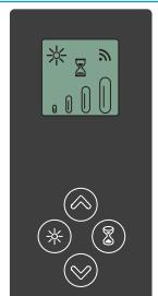
Pure electrical circuit lines without any symbolsWARNING!: Place the hood away from sources of electromagnetic waves (e.g. microwave ovens), which could interfere with the radio control and with the hood electronics. The maximum operating distance is 5 metres, that may vary according to the presence of electromagnetic interferences. Radio control operated at 433.92MHz. The radio control consists of two parts: - the receiver built into the hood;
- the transmitter shown here in the figure.
| DESCRIPTION OF TRANSMITTING COMMANDS | |
 | UPMotor switch-on and speed increase from 1 to 4. Speed 4 is only active for a few minutes. |
 | DOWNSpeed decrease and motor switch-off. |
 | Light on/offShort impulse:turn light on and offLong impulse:adjust intensity |
 | TIMER ON:The motor automatically switches off after 15 min.The function is automatically disabled if the motor is switched off (▽ key) |
 | Command transmission active |
RADIO CONTROL CODE CHANGE
With only one radio control, go directly to point 2.
With several radio controls in the same room, a new code can be created by following the procedure below.

Disconnect the power to the hood before starting the procedure.
1) - CREATE A NEW CODE
The procedure is to be carried out on the radio control.
- Press LIGHT Ⓞ and TIMER ⏻ simultaneously until the display starts flashing.
- Press DOWN ⬇ on the radio control: saving is confirmed by three brief flashes of the display. The new code cancels and replaces the previous default code.

Reconnect the hood to the electrical power supply, making sure that the lights and motor are off.
2) - ASSOCIATING THE RADIO CONTROL WITH THE HOOD USING THE ELECTRONIC PUSHBUTTON PANEL
press TIMER 📊 on the hood pushbutton panel for 2 seconds:
the red LED lights up.
press any key on the radio control within 10 seconds.
RESTORING DEFAULT CODE
the procedure is to be carried out if the hood is disposed of, sold or transferred.

Disconnect the power to the hood before starting the procedure.
- Press UP ⏻ and DOWN ⏻ simultaneously on the radio control for more than 5 seconds: reset is confirmed by three brief flashes of the display.
- Reconnect the hood to the electrical power supply.
- Proceed with associating the hood and the radio control, as described in point 2.
MAINTENANCE

Before cleaning or carrying out maintenance operations, disconnect the equipment by removing the plug or switching off the main switch.
Do not use detergents containing abrasive, acidic or corrosive substances or abrasive cloths.
Regular maintenance guarantees proper operation and performance over time. Special attention is to be paid to the metal anti-grease filters: frequent cleaning of the filters and their supports ensures that no flammable grease is accumulated.
CLEANING OF EXTERNAL SURFACES
You are advised to clean the external surfaces of the hood at least once every 15 days to prevent oily substances and grease from sticking to them. To clean the brushed stainless steel hood, the Manufacturer recommends using "Magic Steel" wipes.
Alternatively and for all the other types of surfaces, it can be cleaned using a damp cloth, slightly moistened with mild, liquid detergent or denatured alcohol. Complete cleaning by rinsing well and drying with soft cloths.

Do not use too much moisture or water around the push button control panel and lighting devices in order to prevent humidity from reaching electronic parts.
The glass panels can only be cleaned with specific, non-corrosive or non-abrasive detergents using a soft cloth.
The Manufacturer declines all responsibility for failure to comply with these instructions.
CLEANING OF INTERNAL SURFACES

Do not clean electrical parts, or parts related to the motor inside the hood, with liquids or solvents.
For the internal metal parts, see the previous paragraph.
METAL ANTI-GREASE FILTERS
It is advised to frequently wash the metal filters (at least once a month) leaving them to soak in boiling water and cleaning solution for 1 hour, taking care not to bend them.
Do not use corrosive, acid or alkaline detergents.
Rinse them well and wait for them to be completely dry before reassembling them.
Washing in a dishwasher is permitted, however, it may cause the filter material to darken: to reduce the possibility of this problem from happening, use low-temperature washes (55°C max.).
To extract and insert the metal anti-grease filters see the assembly instructions.
LIGHTING
The range hood is equipped with high efficiency, low consumption LED lighting with extremely long duration under normal use conditions.
In case of failure, contact the Dealer or an authorised Servicing Department for repairs.
DISPOSAL AFTER END OF USEFUL LIFE

The crossed-out trash or refuse bin symbol on the appliance means that the product is WEEE, i.e. "Waste electrical and electronic equipment", accordingly it must not be disposed of with regular unsort-
ed waste (i.e. with "mixed household waste"), but it must be disposed of separately so that it can undergo specific processing for its re-use, or a specific treatment, to remove and safely dispose of any substances that may be harmful to the environment and remove the raw materials that can be recycled. Proper disposal of these products contributes to saving valuable resources and avoid potential negative effects on personal health and the environment, which may be caused by inappropriate disposal of waste.
You are kindly asked to contact your local authorities for further information regarding the designated waste collection points nearest to you. Penalties for improper disposal of such waste can be applied in compliance with national regulations.
INFORMATION ON DISPOSAL IN EUROPEAN UNION COUNTRIES
The EU WEEE Directive was implemented differently in each country, accordingly, if you wish to dispose of this appliance we suggest contacting your local authorities or dealer to find out what the correct method of disposal is.
INFORMATION ON DISPOSAL IN NON-EUROPEAN UNION COUNTRIES
The crossed-out trash or refuse bin symbol is only valid in the European Union: if you wish to dispose of this appliance in other countries, we suggest contacting your local authorities or dealer to find out what the correct method of disposal is.

WARNING!
The Manufacturer reserves the right to make changes to the equipment at any time and without prior notice. Printing, translation and reproduction, even partial, of this manual are bound by the Manufacturer's authorisation.
Technical information, graphic representations and specifications in this manual are for information purposes and cannot be divulged.
This manual is written in Italian. The Manufacturer is not responsible for any transcription or translation errors.
natural_image
Digital display with icons and symbols (no readable text or labels)
VORSICHT!:
natural_image
Pure electrical circuit lines without any symbolsnatural_image
Pure electrical circuit lines without any symbols
¡ADVERTENCIAS!:
natural_image
Pure electrical circuit lines without any symbols
OSTRZEŻENIA!:
VEILIGHEIDSINSTRUCTIES EN WAARSCHUWINGEN
AFZUIGKAP MET AFVOER NAAR BUITEN

natural_image
Pure electrical circuit lines without any symbolsno interior do exaustor:
natural_image
Pure electrical circuit lines without any symbols
AVISOS!: Posicionar a coifa afastada de fontes de ondas eletromagnéticas (por ex: fornos micro-ondas) que poderão interferir com o contro-to e com a eletrónica do aparelho.
HVILKEN HASTIGHED SKAL MAN VÄLGE?


Motor ON/OFF
Motor OFF
Lang impuls: Skiftende nuancer af lys 2700K-5600K
natural_image
Pure electrical circuit lines without any symbols
ADVARSLER!:
natural_image
Pure electrical circuit lines without any symbols
WARNING!:


Motor ON/OFF
Motor OFF

ADVARSLER!: