
FLIPPER1490 - Kitchen hood FALMEC - Free user manual and instructions
Find the device manual for free FLIPPER1490 FALMEC in PDF.
| Brand | FALMEC |
| Model | FLIPPER1490 |
| Product type | Kitchen hood |
| Installation version | External extraction (suction) or internal recirculation (filtering) |
| Power supply | 220-240 V, 50 Hz |
| Extraction power | 4 speeds (including one timed intensive speed) |
| Control type | Touch electronic control with LED display |
| Lighting | High efficiency LED spots, adjustable color temperature from 2700 K to 5600 K |
| Special functions | Timer (automatic shut-off 15 min), filter maintenance alarm, optional remote control |
| Anti-grease metal filters | Washable (every 30 hours of use, about once a month) |
| Activated carbon filters | Replacement every 3-4 months (depending on use) – optional |
| External surface maintenance | Clean with a soft cloth and neutral detergent or denatured alcohol. For brushed stainless steel: use 'Magic Steel' wipes |
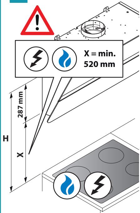
| Safety | Mandatory grounding, automatic shut-off in case of fault, minimum distance of 65 cm above a gas hob |
| Spare parts and repairability | Original spare parts required. Interventions by qualified personnel only. Contact the authorized Service Center. |
| General information | Manual available in several languages. Exact weight and dimensions reported on the rating plate inside the hood. |
Frequently Asked Questions - FLIPPER1490 FALMEC
User questions about FLIPPER1490 FALMEC
0 question about this device. Answer the ones you know or ask your own.
Ask a new question about this device
Download the instructions for your Kitchen hood in PDF format for free! Find your manual FLIPPER1490 - FALMEC and take your electronic device back in hand. On this page are published all the documents necessary for the use of your device. FLIPPER1490 by FALMEC.
USER MANUAL FLIPPER1490 FALMEC
natural_image
Exterior view of a black and silver kitchen air conditioner unit (no visible text or symbols)Design
Flipper
Flipper 85 | Green Tech
INSTRUCTIONS BOOKLET
LIBRETTO ISTRUZIONI ^1T
INSTRUCTIONS BOOKLET EN
FI - VALINNAISELLA POISTOPUTKELLA
NO - VALGFRI SKORSTEIN
other
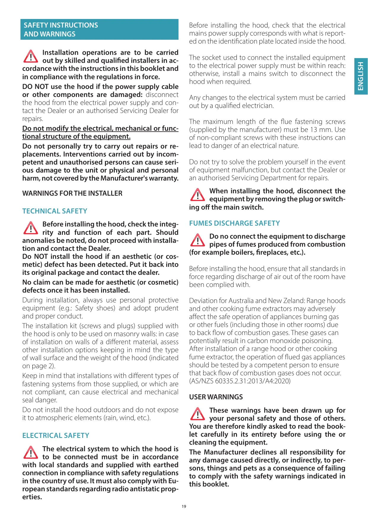
| Dimension | Value | | --------- | ----- | | max | 380 | | 350 | 350 | | 389 | 389 | | 525 | 525 | | 550 / 850 | 550 / 850 |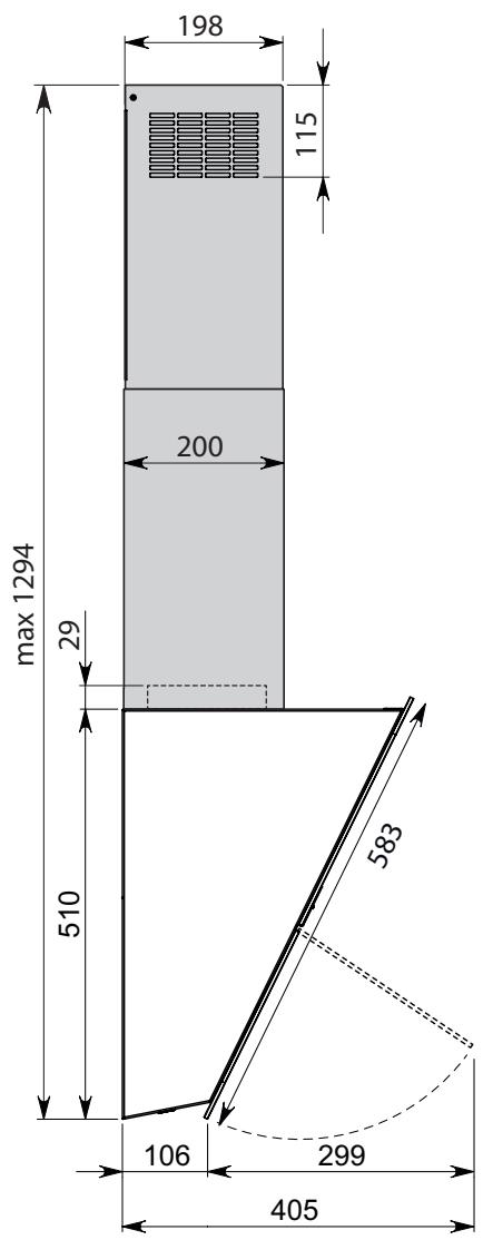
other
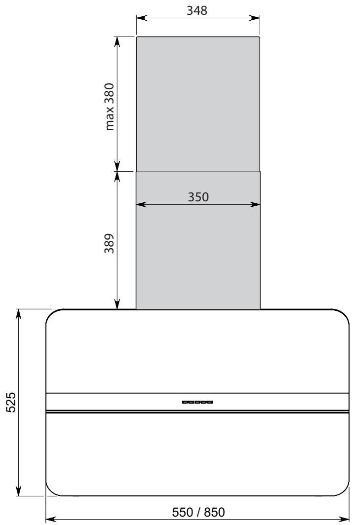
| Dimension | Value | | --------- | ----- | | Height | 198 | | Width | 115 | | Top Margin| 200 | | Bottom Margin| 510 | | Base Margin| 583 | | Top Margin| 106 | | Bottom Margin| 299 | | Total Width| 405 | | Total Height | max 1294 |

Flipper 55: 17 kg
Flipper 85: 25 kg
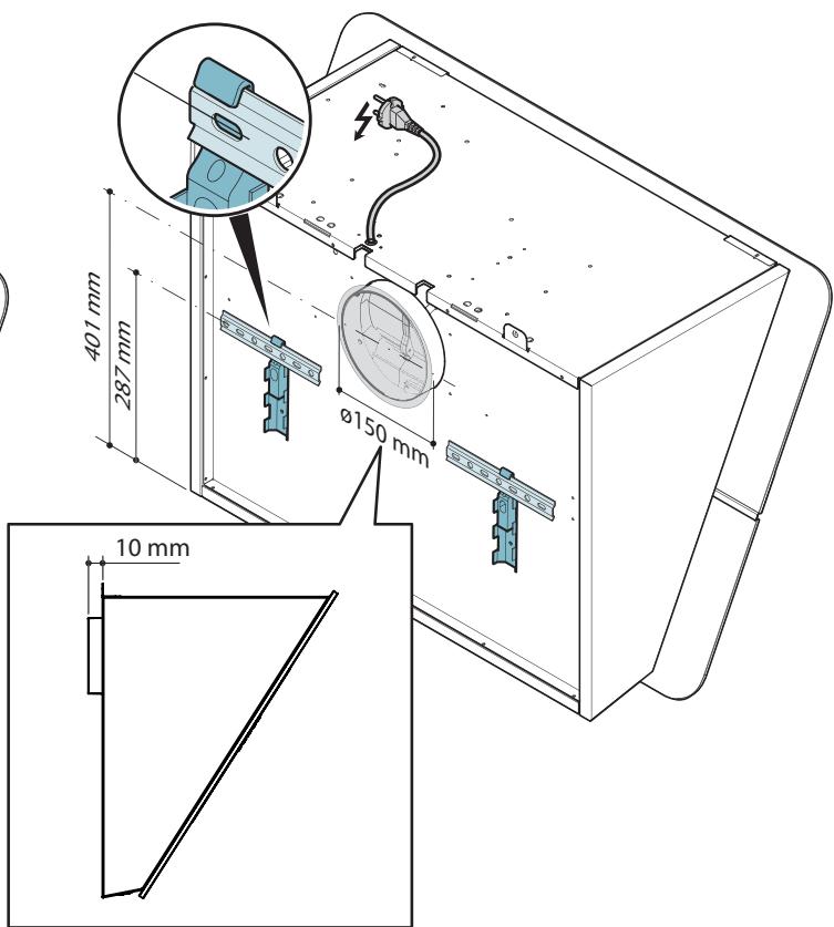

IT - Uscita alternativa posteriore: il motore sporge dal retro della cappa di 10 mm
EN - Alternative rear outlet: the motor protrudes 10 mm from the back of the hood
DE - Alternativer Abzug auf der Rückseite: der Motor steht auf der Rückseite der Abzugshaube um 10 mm über
FR - Sortie alternative arrière : le moteur dépasse de l'arrière de la hotte de 10 mm
ES - Salida alternativa posterior: el motor sobresale 10 mm en la parte posterior de la campana
RU - Дополнительный задний вывод: двигатель с задней стороны вытяжки на 10 мм
PL - Alternatywny tylny wylot: silnik wystaje 10 mm z tyłu okapu
NL - Alternatieve uitgang op de achterkant: de motor steekt 10 mm uit de achterkant van de kap
PT - Saída alternativa traseira: o motor sobressai na parte posterior da coifa em 10 mm
DK - Mulighed for bagudvendt aftræk: motoren rager 10 mm frem fra bagsiden af emhætten
SE - Alternativt bakre uttag: motorn sticker ut från käpans baksida med 10 mm
FI - Vaihtoehtoinen takapoistumistie: moottori tulee ulos 10 mm liesituulettimen takaa
NO - Alternativ bakre utgang: motoren springer frem fra baksiden av ventilatorhetten med 10 mm
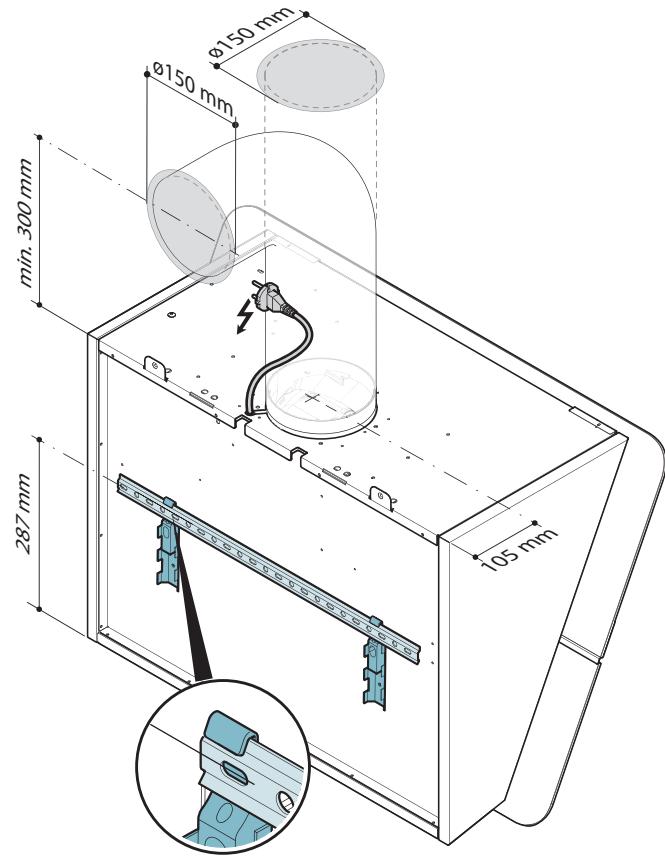
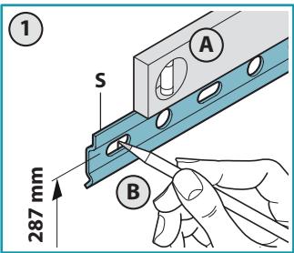
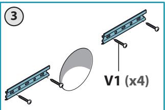
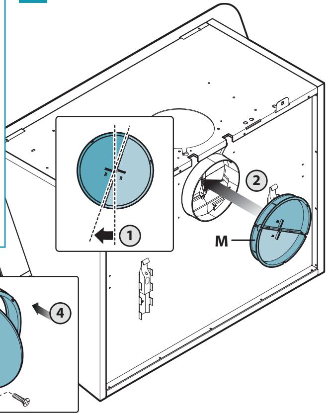
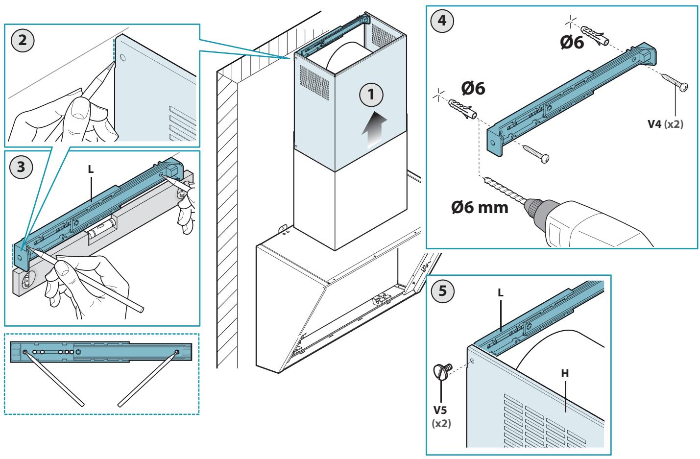
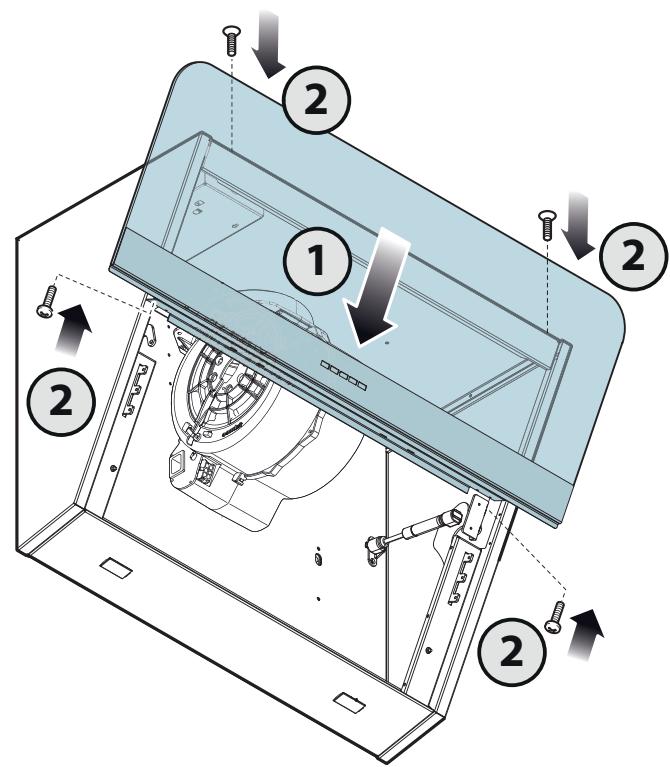
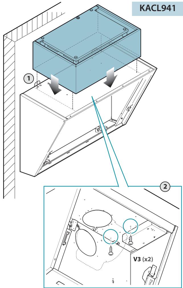
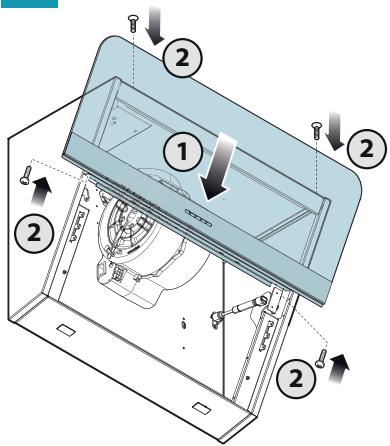
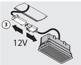
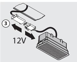
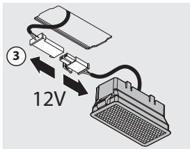
EN - Installation with vertical outlet: Measurements for installation (1). Hood fastening (2).
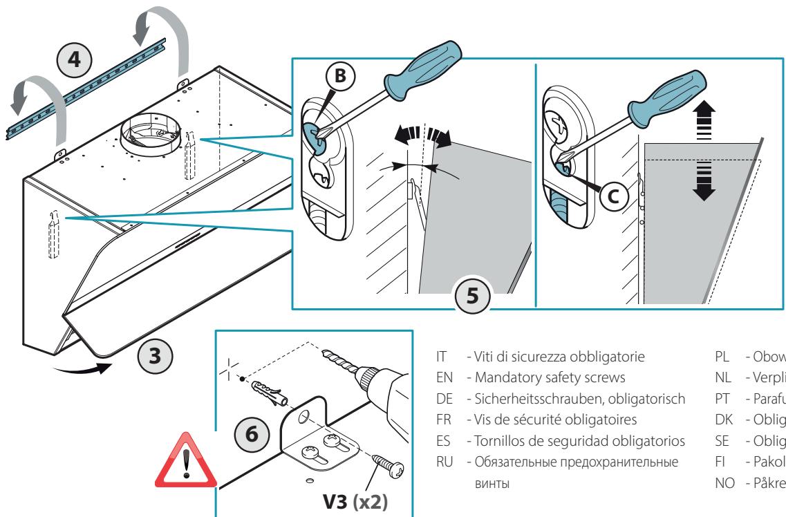
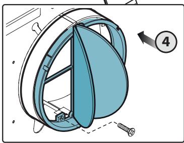
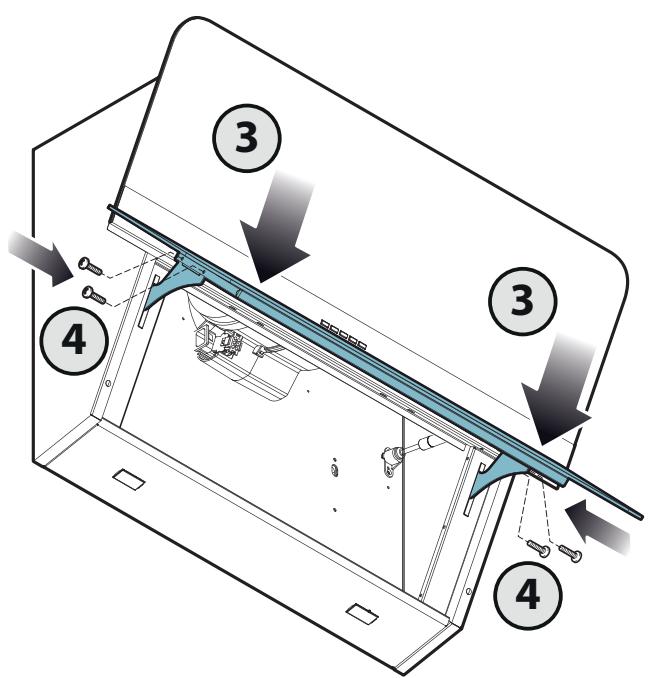
EN - Check valve installation (3) and suction pipe assembly (4).
4
IT - Installazione con uscita posteriore:
Misure per l'installazione (5). Riposizionamento motore (6).
EN - Installation with rear outlet: Measurements for installation (5). Motor repositioning (6).
DE - Installation mit abzug auf der Rückseite:
Maßangaben für die Installation (5). Neupositionierung Motor (6).
FR - Installation avec une sortie arrière:
Mesures pour l'installation (5). Repositionnement du moteur (6).
ES - Instalación con salida posterior:
Medidas para la instalación (5). Reubicación del motor (6).
RU - Установки с задним выводом: Размеры для установки (5). Перепозиционирование двигателя (6).
PL - Instalacji z tylnym wylotem:
Środki montażowe (5). Zmiana położenia silnika (6).
NL - Installatie met uitgang op de achterkant: Maten voor de installatie (5). Hernieuwde plaatsing van de motor (6).
PT - Instalação com saída posterior:
Medidas para a instalação (5). Reposicionamento do motor (6).
DK - Installation med bagudvendt aftræk:
Mål for installation (5). Genpositionering af motor (6).
SE - Installation med bakre uttag:
Installationsåtgärder (5). Ompositionering motor (6).
FI - Takapoistumistien asentamiseksi:
Mitat asennusta varten (5). Moottorin uudelleensijoitus (6).
NO - Installasjon med bakre utgang:
Installasjonsmål (5). Gjenplassering av motor (6).
5
6
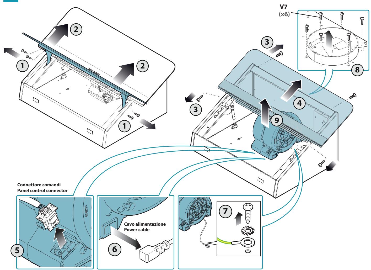
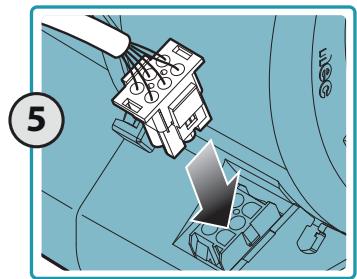
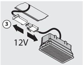
Connettore comandi
Panel control connector


Green Tech
Panel control connector

8
9
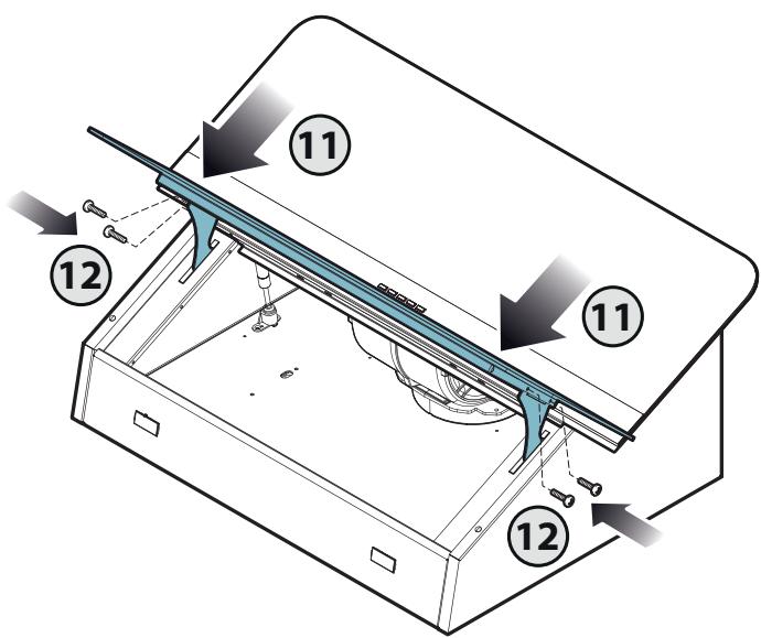
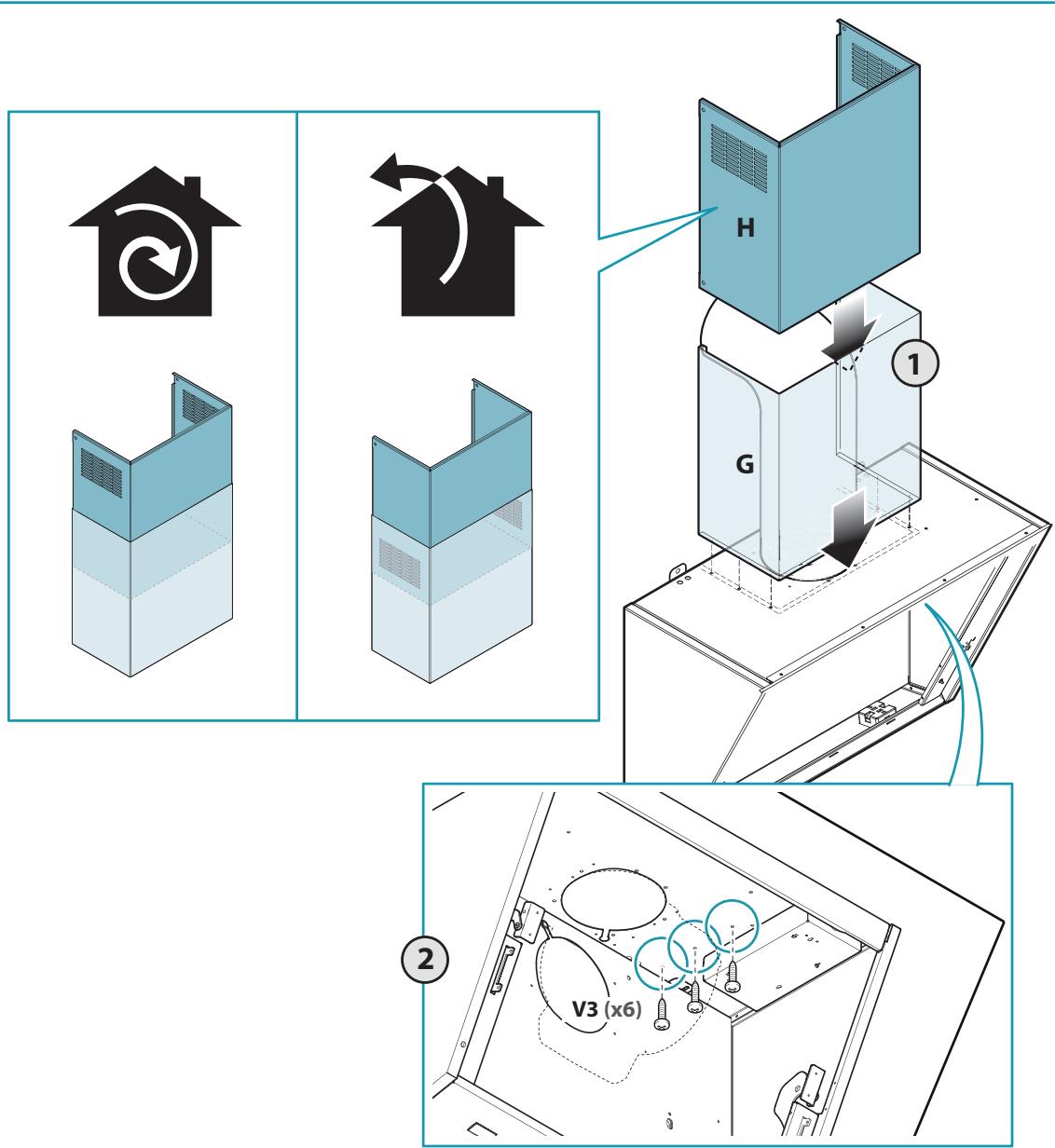
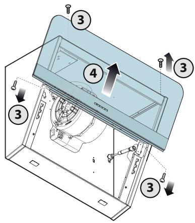
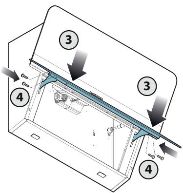
IT - Viti di sicurezza obbligatorie
EN - Mandatory safety screws
DE - Sicherheitsschrauben, obligatorisch
FR - Vis de sécurité obligatoires
ES - Tornillos de seguridad obligatorios
RU - Обязательные предохранительные
винты
PL - Obowiązkowe śruby zabezpieczające
NL - Verplichte veiligheidsschroeven
PT - Parafusos de segurança obrigatórios
DK - Obligatoriske sikkerhedsskruer
SE - Obligatoriska säkerhetsskruvar
FI - Pakolliset varmistusruuvit
NO - Påkrevde sikkerhetsskruer
10
12
13
14

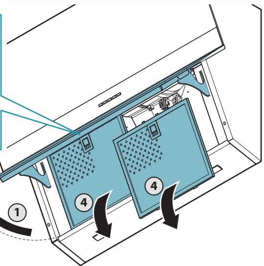
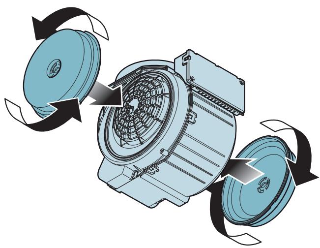
EN - Assembly of factory-fitted filter (15)+(16).
natural_image
Diagram showing a computer monitor with a curved arrow pointing to it, surrounded by triangular shapes (no text or symbols)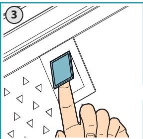
16a
16b
Green Tech
natural_image
Diagram of an electric motor showing internal blades and fan blades with rotation arrows (no text or labels)
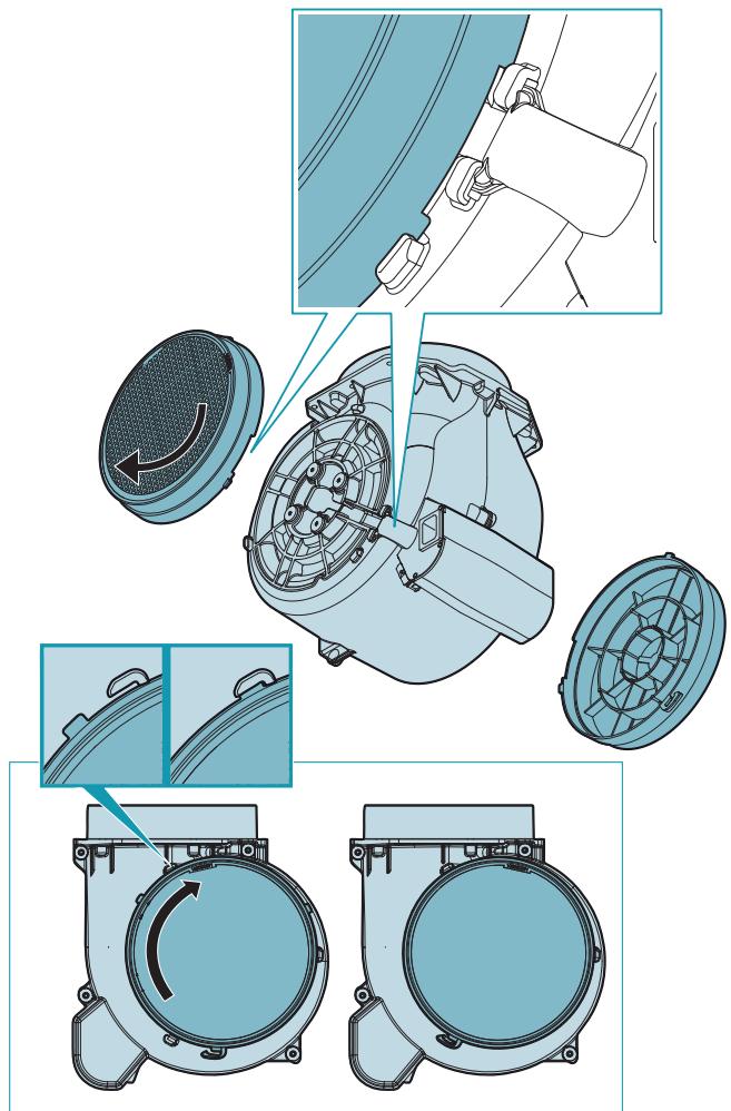
EN - Assembly of foptional filter (17)
DE - Montage des optionalen Filters (17)
18
19
SAFETY INSTRUCTIONS AND WARNINGS
Installation operations are to be carried out by skilled and qualified installers in accordance with the instructions in this booklet and in compliance with the regulations in force.
DO NOT use the hood if the power supply cable or other components are damaged: disconnect the hood from the electrical power supply and contact the Dealer or an authorised Servicing Dealer for repairs.
Do not modify the electrical, mechanical or functional structure of the equipment.
Do not personally try to carry out repairs or replacements. Interventions carried out by incompetent and unauthorised persons can cause serious damage to the unit or physical and personal harm, not covered by the Manufacturer's warranty.
WARNINGS FOR THE INSTALLER
TECHNICAL SAFETY
Before installing the hood, check the integrity and function of each part. Should anomalies be noted, do not proceed with installation and contact the Dealer.
Do NOT install the hood if an aesthetic (or cosmetic) defect has been detected. Put it back into its original package and contact the dealer.
No claim can be made for aesthetic (or cosmetic) defects once it has been installed.
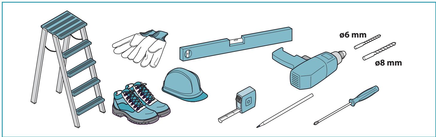
During installation, always use personal protective equipment (e.g.: Safety shoes) and adopt prudent and proper conduct.
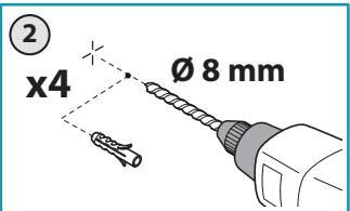
The installation kit (screws and plugs) supplied with the hood is only to be used on masonry walls: in case of installation on walls of a different material, assess other installation options keeping in mind the type of wall surface and the weight of the hood (indicated on page 2).
Keep in mind that installations with different types of fastening systems from those supplied, or which are not compliant, can cause electrical and mechanical seal danger.
Do not install the hood outdoors and do not expose it to atmospheric elements (rain, wind, etc.).
ELECTRICAL SAFETY
The electrical system to which the hood is to be connected must be in accordance with local standards and supplied with earthed connection in compliance with safety regulations in the country of use. It must also comply with European standards regarding radio antistatic properties.
Before installing the hood, check that the electrical mains power supply corresponds with what is reported on the identification plate located inside the hood.
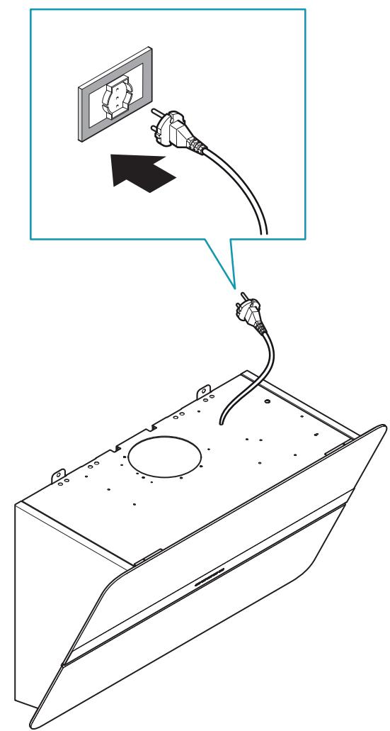
The socket used to connect the installed equipment to the electrical power supply must be within reach: otherwise, install a mains switch to disconnect the hood when required.
Any changes to the electrical system must be carried out by a qualified electrician.
The maximum length of the flue fastening screws (supplied by the manufacturer) must be 13 mm. Use of non-compliant screws with these instructions can lead to danger of an electrical nature.
Do not try to solve the problem yourself in the event of equipment malfunction, but contact the Dealer or an authorised Servicing Department for repairs.
When installing the hood, disconnect the equipment by removing the plug or switching off the main switch.
FUMES DISCHARGE SAFETY
Do no connect the equipment to discharge pipes of fumes produced from combustion (for example boilers, fireplaces, etc.).
Before installing the hood, ensure that all standards in force regarding discharge of air out of the room have been complied with.
Deviation for Australia and New Zealand: Range hoods and other cooking fume extractors may adversely affect the safe operation of appliances burning gas or other fuels (including those in other rooms) due to back flow of combustion gases. These gases can potentially result in carbon monoxide poisoning. After installation of a range hood or other cooking fume extractor, the operation of flued gas appliances should be tested by a competent person to ensure that back flow of combustion gases does not occur. (AS/NZS 60335.2.31:2013/A4:2020)
USER WARNINGS
These warnings have been drawn up for your personal safety and those of others. You are therefore kindly asked to read the booklet carefully in its entirety before using the or cleaning the equipment.
The Manufacturer declines all responsibility for any damage caused directly, or indirectly, to persons, things and pets as a consequence of failing to comply with the safety warnings indicated in this booklet.
It is imperative that this instructions booklet is kept together with the equipment for any future consultation.
If the equipment is sold or transferred to another person, make sure that the booklet is also supplied so that the new user can be made aware of the hood's operation and relative warnings.
After the stainless steel hood has been installed, it will need to be cleaned to remove any residues remaining from the protection adhesive as well as any grease and oil stains which, if not removed, can cause irreversible damage to the hood surface.
To properly clean the unit, the manufacturer recommends using the supplied moist wipes, which are also available sold separately.
Insist on original spare parts.
INTENDED USE
The equipment is solely intended to be used to extract fumes generated from cooking food in non-professional domestic kitchens: any other use is improper. Improper use can cause damage to persons, things, pets and exempts the Manufacturer from any liability.
The equipment can be used by children over the age of 8 and by persons with reduced physical, sensory and mental abilities, or with no experience or knowledge, as long as they do so under supervision or after having received relative instructions regarding safe use of the equipment and understanding of the dangers connected to it.
Children are not to play with the equipment. Cleaning and maintenance by the user must not be carried out by children without supervision.
USE AND CLEANING WARNINGS
Before cleaning or carrying out maintenance operations, disconnect the equipment by removing the plug or switching off the main switch.
Do not use the hood with wet hands or bare feet.
Always check that all electrical parts (lights, extractor fan) are off when the equipment is not being used.
The maximum overall weight of any objects placed or hung (if applicable) on the hood must not exceed 1.5 Kg.
Always supervise the cooking process during the use of deep-fryers: Overheated oil can catch fire.
Do not leave open, unattended flames under the hood.
Do not prepare food over an open flame under the hood.
Never use the hood without the metal anti-grease filters: in this case, grease and dirt will deposit in the equipment and compromise its operation.
Accessible parts of the hood can be hot when used at the same time as the cooking appliances.
Do not carry out any cleaning operations when parts of the hood are still hot.
There can be a risk of fire if cleaning is not carried out according to the instructions and products indicated in this booklet.
Disconnect the main switch when the equipment is not used for long periods of time.
If other appliances that use gas or other fuels are being used at the same time (boiler, stove, fireplaces, etc.), make sure the room where the fumes are discharged is well-ventilated, in compliance with the local regulations.
INSTALLATION
only intended for qualified personnel

Before installing the hood, carefully read the chapter 'SAFETY INSTRUCTIONS AND WARNINGS':
TECHNICAL FEATURES
The technical specifications are exhibited on the labels located inside the hood.
POSITIONING
The minimum distance between the highest part of the cooking equipment and the lowest part of the hood is indicated in the installation instructions.
Generally, when the hood is placed over gas cookers, the distance must be at least 65 cm (25.6"). However, according to standard EN60335-2-31, the minimum distance between the cooker and lower part of the hood can be reduced to the quota reported in the installation instructions.
Should the instructions for the gas cooker specify a greater distance, this must be taken into consideration.
Do not install the hood outdoors and do not expose it to outdoor environment (rain, wind, etc.).
ELECTRICAL CONNECTION
(only intended for qualified personnel)

Disconnect the equipment from electrical mains power supply before carrying out any operations on the hood.
Ensure that the wires inside the hood are not disconnected or cut: in the event of damage, contact your nearest Servicing Department.
Refer to qualified personnel for electrical connections.
Connection must be carried out in compliance with the provisions of law in force.
Before connecting the hood to the electrical mains power supply, check that:
- voltage supply corresponds with what is reported on the data plate located inside the hood;
- the electrical system is compliant and can withstand the load (see the technical specifications located inside the hood);
- the power supply plug and cable do not come into contact with temperatures exceeding 70 °C;
- the power supply system is effectively and properly connected to earth in compliance with regulations in force;
• the socket used to connect the hood is within reach.
In case of:
- devices fitted with cables without a plug: the type of plug to use is a "standardised" one. The wires must be connected as follows: yellow-green for earthing, blue for neutral and brown for the phase. The plug must be connected to an adequate safety socket.
- fixed equipment not provided with a power supply cable and plug, or any other device that ensures disconnection from the electrical mains, with an opening gap of the contacts that enables total disconnection in overvoltage category III conditions.
Said disconnection devices must be provided in the mains power supply in compliance with installation regulations.
The yellow/green earth cable must not be cut off by the switch.
The Manufacturer declines all responsibility for failure to comply with the safety regulations.
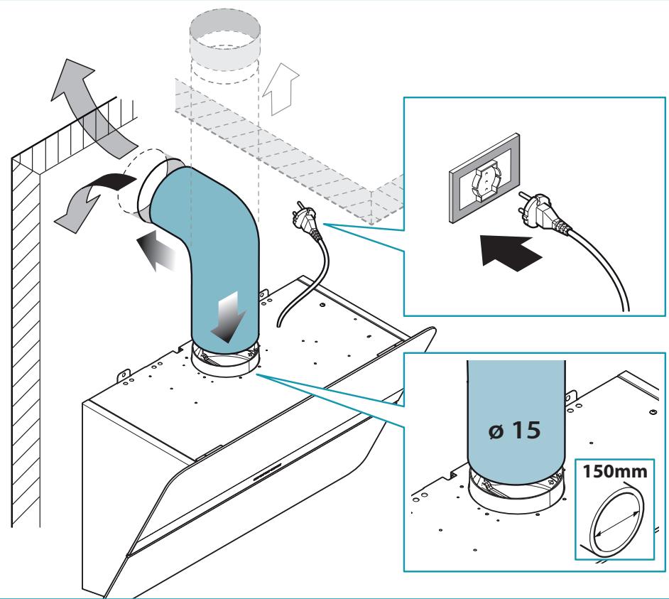
FUMES DISCHARGE
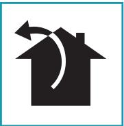
EXTERNAL EXHAUST HOOD (SUCTION)

In this version the fumes and vapours are discharged outside through the exhaust pipe.
To this end, the hood outlet fitting must be connected via a pipe, to an external output.
The outlet pipe must have:
- a diameter not less than that of the hood fitting.
- a slight slope downwards (drop) in the horizontal sections to prevent condensation from flowing back into the motor.
• the minimum required number of bends. - the minimum required length to avoid vibrations and reduce the suction performance of the hood.
You are required to insulate the pipes if it passes through cold environments. In the presence of motors with 800m3/h or higher, a check valve is present to prevent external air flowing back.
Deviation for Germany:
when the kitchen hood is used at the same time as appliances that are powered by energy other than electricity, the negative pressure in the room must not exceed 4 Pa (4 x 10⁻⁵ bar).
HOOD WITH INTERNAL RECIRCULATION (FILTERING)

In this model, the air passes through the charcoal filters to be purified and recycled in the environment.
Ensure that the active carbon filters are assembled into the hood, if not, install them as indicated in the assembly instructions.

In this version the check valve must not be assembled: remove it if it is on the air outlet fitting of the motor.
ASSEMBLY INSTRUCTIONS
only intended for personnel qualified

The hood can be installed in various configurations.
The generic assembly steps apply to all installations; for each case, follow the specific steps provided for the required installation.
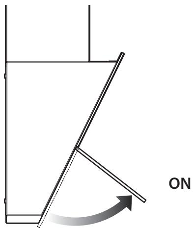
OPERATION
WHEN TO TURN ON THE HOOD?
Switch on the hood at least one minute before starting to cook to direct fumes and vapours towards the suction surface.
After cooking, leave the hood operating until complete extraction of all vapours and odours. By means of the Timer function, it is possible to set auto switch-off function which will allow the hood to turn off automatically after 15 minutes of operation.
WHICH SPEED IS TO BE SELECTED?
1st speed: maintains the circulation of clean air with low electricity consumption.
2nd speed: normal conditions of use.
3rd speed: presence of strong odours and vapours.
4th speed: rapid disposal of odours and vapours.
WHEN SHOULD THE FILTERS BE WASHED OR REPLACED?
The metal filters must be cleaned every 30 hours of operation.
The active carbon filters must be replaced every 3-4 months, depending on the use of the hood.
For further details see the "MAINTENANCE" chap.
ELECTRONIC PUSHBUTTON PANEL (FLIPPER)
| + | - |
| Motor ON/OFFUpon start-up, the speed is that stored at the previous operation. | ||
| + | Increase speed from 1 to 4Speed 4 is only active for a few minutes, then speed 3 activates. | The speeds are indicated by the LEDs on the keys:+ + - Speed 1:+ + - Speed 2:+ + - Speed 3:+ + - Speed 4("+" LED flashing) |
| - | Reduce speed from 4 to 1 | |
| Light on/off | |
| TIMER(red LED flashing)Auto switch-off after 15 min.The function deactivates (red LED off) if:- The TIMER key (💡) is pressed again.- The ON/OFF key (♣) is pressed. | |
| FILTER ALARM(red LED steady on with (♣) off)Anti-grease filter maintenance after approximately 30 hours of operation.Press (💡) the meter for 3 seconds to reset. |
ELECTRONIC PUSHBUTTON PANEL (FLIPPER 85 GREEN TECH)
| + | ÷ | - | # |
| Motor ON/OFFUpon start-up, the speed is that stored at the previous operation. | ||
| + | Increase speed from 1 to 4Speed 4 is only active for a few minutes, then speed 3 activates. | The speeds are indicated by the LEDs on the keys:+ + - Speed 1+ + - Speed 2+ + - Speed 3+ + - Speed 4("+" LED flashing) |
| - | Reduce speed from 4 to 1 | |
| Light on/offShort impulse:turn light on and offLong impulse:change light tone from 2700K to 5600K | ||
| TIMER(red LED flashing)Auto switch-off after 15 min.The function deactivates (red LED off) if:- The TIMER key (♣) is pressed again.- The ON/OFF key (♣) is pressed. | ||
If the pushbutton panel is completely inactive, before contacting the Technical assistance service, disconnect power temporarily to the appliance (about 5"), possibly by acting on the main switch, to restore normal operation.
If this measure has no effect, contact the Technical assistance service.
USING THE RADIO CONTROL (FLIPPER 85 GREEN TECH, OPTIONAL)
WARNING!: Place the hood away from sources of electromagnetic waves (e.g. microwave ovens), which could interfere with the radio control and with the hood electronics.
The maximum operating distance is 5 metres, that may vary according to the presence of electromagnetic interferences.
Radio control operated at 433.92MHz.
The radio control consists of two parts:
- the receiver built into the hood;
- the transmitter shown here in the figure.
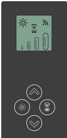 | DESCRIPTION OF TRANSMITTING COMMANDS | |
| UPMotor switch-on and speed increase from 1 to 4. Speed 4 is only active for a few minutes. | ||
| DOWNSpeed decrease and motor switch-off. | ||
| Light ON-OFFShort impulse:turn light on and offLong impulse:change light tone from 2700K to 5600K | ||
| TIMER ON:The motor automatically switches off after 15 min.The function is automatically disabled if the motor is switched off (√ key) | ||
| Command transmission active | ||
ACTIVATION PROCEDURE
Before using the radio control, follow the procedure below on the hood push-button panel:
- Press LIGHT (💡) and TIMER (💡) simultaneously until all LEDs start flashing.
- Release the two keys and press LIGHT (💡) again until all LEDs are lit up.
- Release LIGHT (☐): now the receiver is active.
This procedure is also used to deactivate the receiver.
RADIO CONTROL CODE CHANGE
With only one radio control, go directly to point 2.
With several radio controls in the same room, a new code can be created by following the procedure below.

Disconnect the power to the hood before starting the procedure.
1) - CREATE A NEW CODE
The procedure is to be carried out on the radio control.
- Press LIGHT ⚙️ and TIMER ⏱ simultaneously until the display starts flashing.
- Press DOWN ⬇ on the radio control: saving is confirmed by three brief flashes of the display. The new code cancels and replaces the previous default code.
Reconnect the hood to the electrical power supply, making sure that the lights and motor are off.
2) - ASSOCIATING THE RADIO CONTROL WITH THE HOOD USING THE ELECTRONIC PUSHBUTTON PANEL
press TIMER (💡) on the hood pushbutton panel for 2 seconds:
the red LED lights up.
press any key on the radio control within 10 seconds.
RESTORING DEFAULT CODE
the procedure is to be carried out if the hood is disposed of, sold or transferred.

Disconnect the power to the hood before starting the procedure.
- Press UP ⬇ and DOWN √ simultaneously on the radio control for more than 5 seconds: reset is confirmed by three brief flashes of the display.
- Reconnect the hood to the electrical power supply.
- Proceed with associating the hood and the radio control, as described in point 2.
MAINTENANCE

Before cleaning or carrying out maintenance operations, disconnect the equipment by removing the plug or switching off the main switch. Do not use detergents containing abrasive, acidic
or corrosive substances or abrasive cloths.
Regular maintenance guarantees proper operation and performance over time. Special attention is to be paid to the metal anti-grease filters: frequent cleaning of the filters and their supports ensures that no flammable grease is accumulated.
CLEANING OF EXTERNAL SURFACES
You are advised to clean the external surfaces of the hood at least once every 15 days to prevent oily substances and grease from sticking to them. To clean the brushed stainless steel hood, the Manufacturer recommends using "Magic Steel" wipes. Alternatively and for all the other types of surfaces, it can be cleaned using a damp cloth, slightly moistened with mild, liquid detergent or denatured alcohol.
Complete cleaning by rinsing well and drying with soft cloths.

Do not use too much moisture or water around the push button control panel and lighting devices in order to prevent humidity from reaching electronic parts.
The glass panels can only be cleaned with specific, non-corrosive or non-abrasive detergents using a soft cloth.
The Manufacturer declines all responsibility for failure to comply with these instructions.
CLEANING OF INTERNAL SURFACES

Do not clean electrical parts, or parts related to the motor inside the hood, with liquids or solvents.
For the internal metal parts, see the previous paragraph.
METAL ANTI-GREASE FILTERS
It is advised to frequently wash the metal filters (at least once a month) leaving them to soak in boiling water and cleaning solution for 1 hour, taking care not to bend them.
Do not use corrosive, acid or alkaline detergents.
Rinse them well and wait for them to be completely dry before reassembling them. Washing in a dishwasher is permitted, however, it may cause the filter material to darken: to reduce the possibility of this problem from happening, use low-temperature washes (55°C max.).
To extract and insert the metal anti-grease filters see the assembly instructions.
ACTIVE CARBON FILTERS
These filters retain the odours in the air that passes through them. The purified air is recirculated into the environment.
The active carbon filters must be replaced on average every 3-4 months under normal conditions of use.
See assembly instructions to replace the active carbon filters.
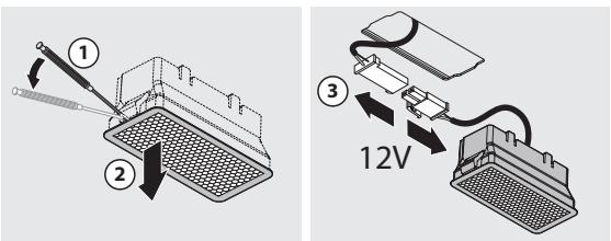
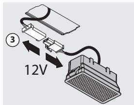
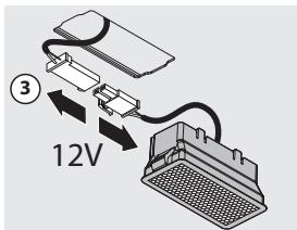
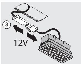
LIGHTING
The range hood is equipped with high efficiency, low consumption LED spotlights with an extremely long life-span under normal use conditions.
Should the LED spotlight need to be replaced, proceed as shown in the figure.
DISPOSAL AFTER END OF USEFUL LIFE

The crossed-out trash or refuse bin symbol on the appliance means that the product is WEEE, i.e. "Waste electrical and electronic equipment", accordingly it must not be disposed of with regular unsort-
ed waste (i.e. with "mixed household waste"), but it must be disposed of separately so that it can undergo specific processing for its re-use, or a specific treatment, to remove and safely dispose of any substances that may be harmful to the environment and remove the raw materials that can be recycled. Proper disposal of these products contributes to saving valuable resources and avoid potential negative effects on personal health and the environment, which may be caused by inappropriate disposal of waste.
You are kindly asked to contact your local authorities for further information regarding the designated waste collection points nearest to you. Penalties for improper disposal of such waste can be applied in compliance with national regulations.
INFORMATION ON DISPOSAL IN EUROPEAN UNION COUNTRIES
The EU WEEE Directive was implemented differently in each country, accordingly, if you wish to dispose of this appliance we suggest contacting your local authorities or dealer to find out what the correct method of disposal is.
INFORMATION ON DISPOSAL IN NON-EUROPEAN UNION COUNTRIES
The crossed-out trash or refuse bin symbol is only valid in the European Union: if you wish to dispose of this appliance in other countries, we suggest contacting your local authorities or dealer to find out what the correct method of disposal is.

WARNING!
The Manufacturer reserves the right to make changes to the equipment at any time and without prior notice. Printing, translation and reproduction, even partial, of this manual are bound by the Manufacturer's authorisation.
Technical information, graphic representations and specifications in this manual are for information purposes and cannot be divulged.
This manual is written in Italian. The Manufacturer is not responsible for any transcription or translation errors.

Moteur ON/OFF
FILTRES AU CHARBON ACTIF
ÉLIMINATION EN FIN DE VIE

UTYLIZACJA PO ZAKOŃCZENIU OKRESU EKSPLOATACJI

VEILIGHEIDSINSTRUCTIES EN WAARSCHUWINGEN
AFZUIGKAP MET AFVOER NAAR BUITEN
HVILKEN HASTIGHED SKAL MAN VÄLGE?
BORTSKAFFELSE VED ENDT LEVETID

KASSERING I SLUTET AV LIVSLÄNGDEN
HÄVITTÄMINEN KÄYTÖN LOPUTTUA
KASSERING VED ENDT LEVETID
