
WV-CW384E - Surveillance Camera PANASONIC - Free user manual and instructions
Find the device manual for free WV-CW384E PANASONIC in PDF.

| Product type | Color surveillance camera with motorized lens |
| Brand | Panasonic |
| Model | WV-CW384E |
| Image sensor | 1/3-inch interline CCD, 752 (H) × 582 (V) pixels |
| Horizontal resolution | 540 TV lines (color mode, high) / 570 TV lines (monochrome mode) |
| Minimum illumination | Color: 0.65 lx (F1.6, high AGC, NIGHT VISION OFF); B/W: 0.09 lx |
| Dynamic range | Super Dynamic 3: approx. 160 times greater than conventional cameras |
| Lens | Focal length 5-40 mm (8x zoom), F1.6 (WIDE) - F1.9 (TELE), focus 1.2 m to ∞ |
| Angle of view | Horizontal: 6.6° (TELE) - 52.0° (WIDE); Vertical: 5.6° - 39.0° |
| Power supply | 24 V AC 50 Hz, 18 W or 12 V DC, 560 mA |
| Video output | Composite PAL 1.0 Vp-p / 75 Ω on BNC; 3.5 mm mini jack for setup monitor |
| Synchronization | VD2 (multiplexed), Line lock (network lock), Internal |
| Main functions | Super-Dynamic 3, ABF (auto back focus), motion detection, digital noise reduction, auto night mode, 2x electronic zoom |
| Menu settings | Language (FR, EN, DE, etc.), camera ID, ALC, shutter speed, AGC, white balance, privacy zone, image stabilizer |
| Operating temperature | -30 °C to +50 °C (24 V AC) / -10 °C to +50 °C (12 V DC); humidity ≤ 90% |
| Protection rating | IP66 (waterproof against water jets) if installation and sealing are correct |
| Dimensions (W × H × D) | 82 mm × 78 mm × 301 mm |
| Weight | 1.5 kg (camera only) |
| Materials | Housing: silver lacquered AES resin; lens cover: silver lacquered die-cast aluminum |
| Supplied accessories | Mounting plate, sun visor, adapter housing, waterproof tape, desiccant, various screws |
| Maintenance and cleaning | Clean the housing with a dry cloth; lens with optical paper or ethanol-dipped cotton swab |
| Safety | Grounding mandatory; disconnect before maintenance; have repairs done by a professional |
| Repairability / Spare parts | No user-serviceable parts; contact Panasonic support or an authorized installer |
Frequently Asked Questions - WV-CW384E PANASONIC
User questions about WV-CW384E PANASONIC
0 question about this device. Answer the ones you know or ask your own.
Ask a new question about this device
Download the instructions for your Surveillance Camera in PDF format for free! Find your manual WV-CW384E - PANASONIC and take your electronic device back in hand. On this page are published all the documents necessary for the use of your device. WV-CW384E by PANASONIC.
USER MANUAL WV-CW384E PANASONIC
Operating Instructions
Color CCTV Cameras
Model Nos. WV-CW384E
WV-CW380/G
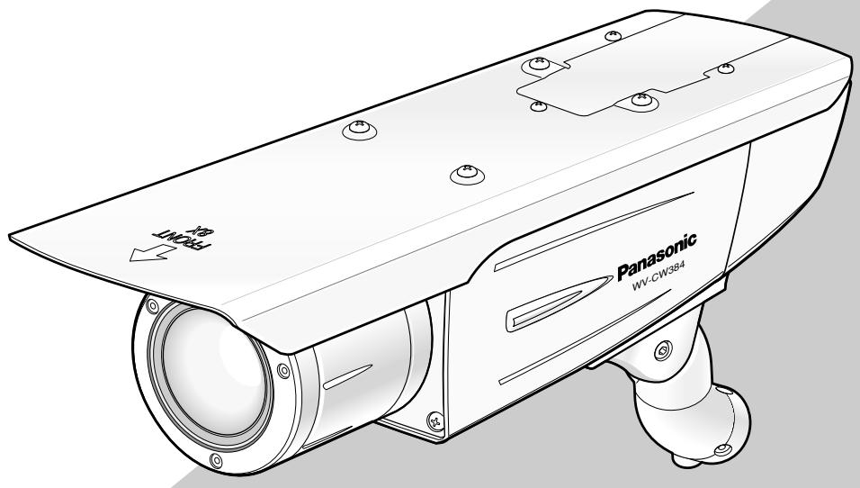
natural_image
Line drawing of a Panasonic security camera with labeled components (no text or symbols beyond branding)WV-CW384 is shown above.
Before attempting to connect or operate this product, please read these instructions carefully and save this manual for future use.
The model number is abbreviated in some descriptions in this manual.
ENGLISH VERSION
We declare under our sole responsibility that the product to which this declaration relates is in conformity with the standards or other normative documents following the provisions of Directives 2006/95/EC and 2004/108/EC.
• This apparatus must be earthed.
- All work related to the installation of this product should be made by qualified service personnel or system installers.
- The connections should comply with local electrical code.
CAUTION:
Before attempting to connect or operate this product, please read the label on the bottom.
CAUTION
RISK OF ELECTRIC SHOCK DO NOT OPEN

CAUTION: TO REDUCE THE RISK OF ELECTRIC SHOCK,
DO NOT REMOVE COVER (OR BACK).
NO USER-SERVICEABLE PARTS INSIDE.
REFER SERVICING TO QUALIFIED SERVICE PERSONNEL.

The lightning flash with arrowhead symbol, within an equilateral triangle, is intended to alert the user to the presence of uninsulated "dangerous voltage" within the product's enclosure that may be of sufficient magnitude to constitute a risk of electric shock to persons.

The exclamation point within an equilateral triangle is intended to alert the user to the presence of important operating and maintenance (servicing) instructions in the literature accompanying the appliance.
Turn the power off at the mains to disconnect the main power for all unit.
CAUTION:
An ALL-POLE MAINS SWITCH with a contact separation of at least 3 mm in each pole shall be incorporated in the electrical installation of the building.
For U.K.
FOR YOUR SAFETY PLEASE READ THE FOLLOWING TEXT CAREFULLY.
WARNING: This apparatus must be earthed.
IMPORTANT
The wires in this mains lead are coloured in accordance with the following code.
Green-and-yellow:
Blue:
Brown:
Earth
Neutral
Live
As the colours of the wire in the mains lead of this appliance may not correspond with the coloured markings identifying the terminals in your plug, proceed as follows.
The wire which is coloured green-and-yellow must be connected to the terminal in the plug which is marked with the letter E or by the earth symbol ± or coloured green or green-and-yellow.
The wire which is coloured blue must be connected to the terminal in the plug which is marked with the letter N or coloured black.
The wire which is coloured brown must be connected to the terminal in the plug which is marked with the letter L or coloured red.
CONTENTS
Important Safety Instructions ....4
Limitation of Liability 5
Disclaimer of Warranty 5
Preface 6
Features 6
Precautions 7
Major Operating Controls and Their Functions 8
Precautions for Installation 9
Installations/Connections 10
■ Preparations ....10
■ Camera installation ....10
About Setup Menus ....21
■ Basic operation ....22
Setting Procedures 23
Language Setup (LANGUAGE SETUP) ....23
-
Camera Identification Setting (CAMERA ID) 23
-
Light Control Mode Setting (ALC) 24
-
Shutter Speed Setting (SHUTTER) 25
-
Gain Control Setting (AGC) ......26
-
Electronic Sensitivity Enhancement (SENS UP) 26
-
Synchronization Setting (SYNC) 26
-
White Balance Setting (WHITE BAL) 27
-
Motion Detection Setting (MOTION DET) ......27
-
Digital Noise Reduction Setting (DNR) 29
-
Resolution Setting (RESOLUTION) ......29
-
Black and White Mode Setting (BW MODE) 29
-
Privacy Zone Setting (PRIVACY ZONE) ....30
-
Electronic Zoom (EL-ZOOM) 30
-
Auto Image Stabilizer (STABILIZER) 31
-
LED Setting (LED) 31
-
Back-focus Setting (BACK-FOCUS SETUP) ....31
-
Special Menu (SPECIAL SETUP) 32
Troubleshooting 34
Specifications 35
Standard Accessories ....36
Important Safety Instructions
1) Read these instructions.
2) Keep these instructions.
3) Heed all warnings.
4) Follow all instructions.
5) Clean only with dry cloth.
6) Do not block any ventilation openings. Install in accordance with the manufacturer's instructions.
7) Do not install near any heat sources such as radiators, heat registers, stoves, or other apparatus (including amplifiers) that produce heat.
8) Do not defeat the safety purpose of the polarized or grounding-type plug. A polarized plug has two blades with one wider than the other. A grounding type plug has two blades and a third grounding prong. The wide blade or the third prong are provided for your safety. If the provided plug does not fit into your outlet, consult an electrician for replacement of the obsolete outlet.
9) Protect the power cord from being walked on or pinched particularly at plugs, convenience receptacles, and the point where they exit from the apparatus.
10) Only use attachments/accessories specified by the manufacturer.
11) Use only with the cart, stand, tripod, bracket, or table specified by the manufacturer, or sold with the apparatus. When a cart is used, use caution when moving the cart/apparatus combination to avoid injury from tip-over.

natural_image
Symbolic illustration of a person climbing a ladder inside a circle with a diagonal line (no text or symbols)12) Unplug this apparatus during lightning storms or when unused for long periods of time.
Limitation of Liability
THIS PUBLICATION IS PROVIDED "AS IS" WITHOUT WARRANTY OF ANY KIND, EITHER EXPRESS OR IMPLIED, INCLUDING BUT NOT LIMITED TO, THE IMPLIED WARRANTIES OF MERCHANTABILITY, FITNESS FOR ANY PARTICULAR PURPOSE, OR NON-INFRINGEMENT OF THE THIRD PARTY'S RIGHT.
THIS PUBLICATION COULD INCLUDE TECHNICAL INACCURACIES OR TYPOGRAPHICAL ERRORS.
CHANGES ARE ADDED TO THE INFORMATION HEREIN, AT ANY TIME, FOR THE IMPROVEMENTS OF THIS PUBLICATION AND/OR THE CORRESPONDING PRODUCT (S).
Disclaimer of Warranty
IN NO EVENT SHALL Panasonic Corporation BE LIABLE TO ANY PARTY OR ANY PERSON, EXCEPT FOR REPLACEMENT OR REASONABLE MAINTENANCE OF THE PRODUCT, FOR THE CASES, INCLUDING BUT NOT LIMITED TO BELOW:
(1) ANY DAMAGE AND LOSS, INCLUDING WITHOUT LIMITATION, DIRECT OR INDIRECT, SPECIAL, CONSEQUENTIAL OR EXEMPLARY, ARISING OUT OF OR RELATING TO THE PRODUCT;
(2) PERSONAL INJURY OR ANY DAMAGE CAUSED BY INAPPROPRIATE USE OR NEGLIGENT OPERATION OF THE USER;
(3) UNAUTHORIZED DISASSEMBLE, REPAIR OR MODIFICATION OF THE PRODUCT BY THE USER;
(4) INCONVENIENCE OR ANY LOSS ARISING WHEN IMAGES ARE NOT DISPLAYED, DUE TO ANY REASON OR CAUSE INCLUDING ANY FAILURE OR PROBLEM OF THE PRODUCT;
(5) ANY PROBLEM, CONSEQUENTIAL INCONVENIENCE, OR LOSS OR DAMAGE, ARISING OUT OF THE SYSTEM COMBINED BY THE DEVICES OF THIRD PARTY;
(6) ANY CLAIM OR ACTION FOR DAMAGES, BROUGHT BY ANY PERSON OR ORGANIZATION BEING A PHOTOGENIC SUBJECT, DUE TO VIOLATION OF PRIVACY WITH THE RESULT OF THAT SURVEILLANCE-CAMERA'S PICTURE, INCLUDING SAVED DATA, FOR SOME REASON, BECOMES PUBLIC OR IS USED FOR THE PURPOSE OTHER THAN SURVEILLANCE.
Preface
Panasonic's WV-CW384 and WV-CW380 cameras introduce high picture quality by use of Super-Dynamic 1/3-inch type {1/3"} CCD and digital signal processing LSIs. These cameras are designed for installation on the wall or the ceiling, using the supplied camera mount bracket.
Features
Introduction of SUPER-D3 (super dynamic function)
Integration of SUPER-D3 into the CCD and signal processing circuit has achieved approximately 160 times higher dynamic range as compared with conventional camera. Therefore, a photographic subject on which much illuminance difference exists resulting from bright and dark areas can be naturally displayed in an image.
Auto back focus function (ABF) equipped
The back focus adjustment can be performed through the operation buttons on this unit and the setup menu.
The back focus can be remotely adjusted through the system controller (option) even after installation of this unit. The auto back focus function also allows users to correct out of focus when changing between color and black-and-white images.
High sensitivity achieved thanks to noise reduction function
The introduction of low noise circuit design has achieved excellently high sensitivity resulting in the minimum illuminance of 0.65 lx in the color mode and 0.09 lx in the black-and-white mode.
Night monochrome image activation function equipped
No operation is required at night because the image automatically changes from the color mode to the black-and-white mode at low illuminance.
Motion detector function equipped
If motion is observed in the monitor, the camera is covered with a cloth, a cap, or the like, or the camera direction is changed during monitoring, an alarm signal is provided.
Precautions
This product has no power switch.
Power is supplied from an external 12 V DC/24 V AC (WV-CW384) or 220 V to 240 V AC (WV-CW380) power-supply device. Refer to service personnel for how to turn on/off the power.
To keep on using with stable performance
- Parts of this product may deteriorate and it may shorten lifetime of the product when using in locations subject to high temperatures and high humidity.
Do not expose the product to direct heat such from a heater. - Use this product at temperature within -30^ to +50^^* and humidity below 90% .
* -10^ to +50^ at 12 V DC
Do not drop metallic parts through slots.
This could permanently damage this product. Turn the power off immediately and contact qualified service personnel for service.
Do not rub the edges of metal parts with your hand.
Failure to observe this may cause injury.
Do not attempt to disassemble this product.
To prevent electric shock, do not remove screws or covers.
There are no user-serviceable parts inside.
Ask qualified service personnel for servicing.
Handle this product with care.
Do not abuse this product. Avoid striking, shaking, etc.
The product could be damaged by improper handling or storage.
Cleaning this product body
Turn the power off when cleaning the product. Use a dry cloth to clean the product. Do not use strong abrasive detergent when cleaning the product body. When the dirt is hard to remove, use a mild detergent and wipe gently. Then, wipe off the remaining detergent with a dry cloth.
Otherwise, it may cause discoloration. When using a chemical cloth for cleaning, read the caution provided with the chemical cloth product.
Clean the lens with care.
Do not clean the lens with strong or abrasive detergents.
Use lens tissue or a cotton tipped applicator and ethanol.
Discoloration on the CCD color filter
When continuously shooting a bright light source such as a spotlight, the color filter of the CCD may have deteriorated and it may cause discoloration.
Even when changing the fixed shooting direction after continuously shooting a spotlight for a certain period, the discoloration may remain.
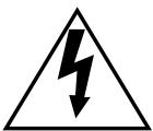
Do not aim this product at strong light sources.
A light source such as a spot light causes a blooming (light bleeding) or a smear (vertical lines).
About the dehumidifying device
- This product has dehumidifying device to keep the inside at low moisture level, preventing condensation and quickly dissipating dew if produced.
- Dew may be produced depending on the conditions of temperature, humidity, winds, and rain, and it may take time to dehumidify.
- Never seal the surfaces of the dehumidifying device.

Turn the circuit breaker off which supplies this product with the power when abnormal conditions are encountered.
Do not operate this product beyond the specified temperature, humidity or power source ratings.
Use this product at temperature within -30^ to +50^^* and humidity below 90% . The input power source is 12 V DC/24 V AC (WV-CW384) or 220 V to 240 V AC (WV-CW380).
* -10^ to +50^ at 12VDC
Use at low temperatures
- To operate the camera at temperatures of -10^ or lower, it will take 30 minutes or more after turning on the power to warm up the camera.
- Images may be disturbed because the built-in heater is automatically toggled between ON and OFF resulting from a change in usage environment.
What to do if OVER HEAT appears on the display.
This message indicates that the inside of this product has become extremely hot. Immediately turn off the product and contact your dealer.

① Monitor output jack (ø3.5 mm mini jack (monaural))
Connects to a monitor for adjustment to adjust the view angle and focus.
② Zoom adjustment ring
Adjusts the zoom position. ( page 16)
③ Auto back focus button
Activates the auto back focus function.
④ Focus lock knob
Locks the focal point. ( page 16)
⑤ Sunshield (accessory)
⑥ Front glass
⑦ Lens cover
Protects the lens. The lens cover is removed at lens adjustment. After lens adjustment, the fixing screws shall be securely tightened. ( page 15)
⑧ LED
Lights, blinks, or goes off depending on settings. ( page 31)
⑨ Tilting lock screw
Locks the tilt position. ( page 15)
⑩ Panning lock screw
Locks the panning position. ( page 15)
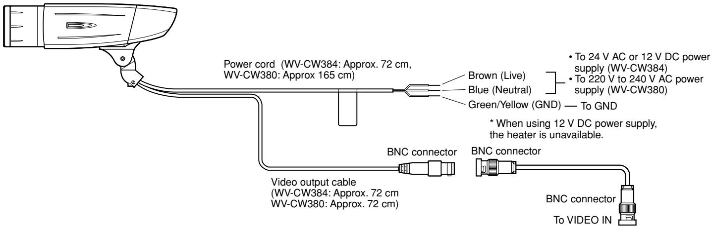
⑪ Power cord
Caution:
- This cord supplies 12 V DC/24 V AC (WV-CW384) or 220 V to 240 V AC (WV-CW380) from an external power source.
⑫ Video output cable
⑬ Safety wire
⑭ Rear cover
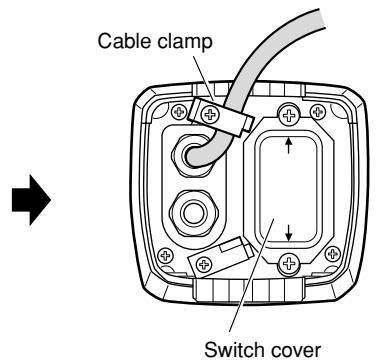
⑮ Switch cover
This cover is removed at operating the operation buttons. After the button operation, the fixing screws shall be securely tightened. ( page 17)
⑯ - ⑳ Operation buttons
⑯ Up button (UP)
⑰ Right button (RIGHT)
⑱ Down button (DOWN)
⑲ Left button (LEFT)
⑳ Set button (SET)
②1 Camera mount bracket (accessory)
②2 Adapter box (accessory)
Precautions for Installation
Installing place
Contact your dealer for assistance if you are unsure of an appropriate place in your particular environment.
Make sure that the installation area is strong enough to hold this product, such as a concrete ceiling. When the installation area is not strong enough, reinforce and strengthen it.
Avoid installing this product in the following locations.
- Locations where a chemical agent is used such as a swimming pool
- Locations subject to steam and oil smoke such as a kitchen
- Locations near flammable gas or vapor
- Locations where radiation or x-ray emissions are produced
- Locations subject to strong magnetic field or radio waves
- Locations where corrosive gas is produced
- Locations where it may be damaged by briny air such as seashores
- Locations where the temperature is not within -30^ to +50^^* .
* -10^ to +50^ at 12VDC - Locations subject to vibrations (This product is not designed for on-vehicle use.)
Be sure to remove this product if it is not in use.
White balance
White balance may be not adjusted appropriately in the following cases.
- When a subject is extremely less white or nearly single colored
- When a subject is in the outdoors in the morning or evening or in the low illuminance state
- When a subject is in the atmosphere of extremely different color temperature (e.g. under color illumination)
Keep the video output cable away from the lighting cable.
Failure to observe this may cause noise.
Radio interference
When this product is used near TV/radio antenna, strong electric field or magnetic field (near a motor or a transformer), images may be distorted and noise sound may be produced. In such a case, run the camera cable through specialized conduit tubes.
Mounting screws
Only the fixing screws are provided to fix this product with the provided mount bracket. It is necessary to procure screws or bolts to mount the product. Prepare them according to the material and strength of the area where the product is to be installed.
The screws and bolts must be tightened with an appropriate tightening torque according to the material and strength of the installation area. After tightening the screws or bolts, perform visual check to ensure tightening is enough and there is no backlash.
Piping for cables
If this product is operated outdoors, be sure to install connecting tubes and run the cables through the tubes to protect the cables from being frozen or direct sunlight.
Caution:
ONLY CONNECT THIS TO 24 V AC OR 12 V DC CLASS 2 POWER SUPPLY. (WV-CW384)
■ Preparations
The camera can be mounted either of the following ways.
- To mount the camera directly on the wall
- To mount the camera on the wall using a adapter box
Note:
- The screws that secure the camera mount bracket on a wall are not supplied. Prepare the screws according to the material, structure, strength and other factors of the mounting area and the total weight of objects to be mounted.
[Mounting position on the wall]
Important:
- Prepare the mounting screws according to the material of the area where the camera mount bracket is to be installed. In this case, wood screws and nails should not be used. Recommended tightening torque M4: 1.6 N·m
- Required pull-out capacity of a single screw/bolt is 196 N or more.
- If a ceiling board such as plaster board is too weak to support the total weight, the area shall be sufficiently reinforced.
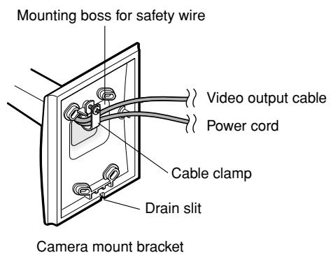
- When using the provided adapter box, make sure that the drain slits do not face upward.
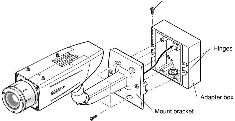
■ Camera installation
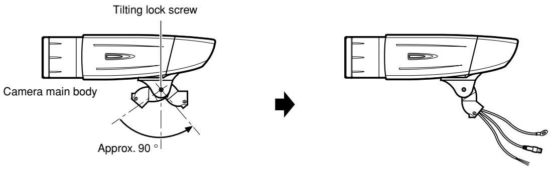
1 Secure the camera to the camera mount bracket
The tilt angle is locked downward at shipment.
- Loosen the tilting lock screw approx. 1 rotation and adjust the tilt angle of the camera to the horizontal position.
- Tighten the tilting lock screw again after tilt angle adjustment.
Note:
- Use a hexagonal wrench with width across flats of 4 mm (locally procured) to loosen or tighten the tilting lock screw.
-
Pass the video output cable, power cord and safety wire through the camera mount bracket from the camera side to the wall side and use the cable clamp to bundle the cables and wire.
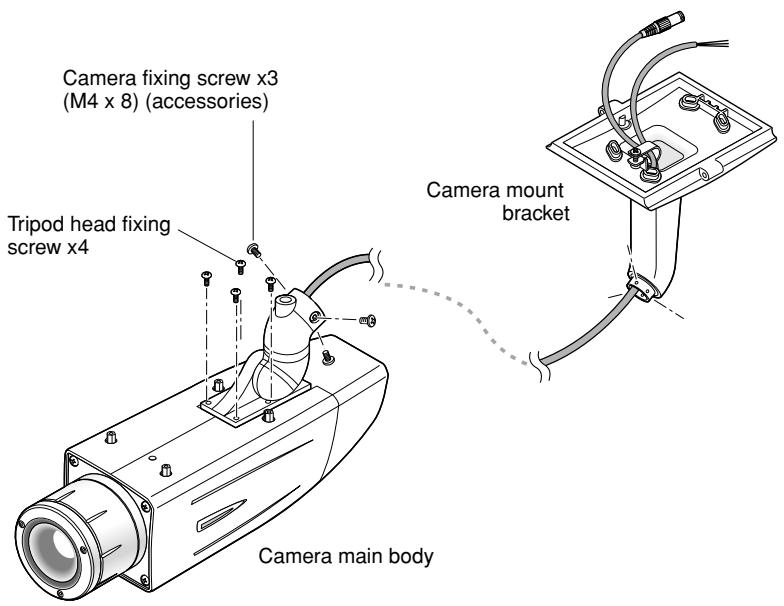
-
Secure the camera to the camera mount bracket with the 3 camera fixing screws (accessories).
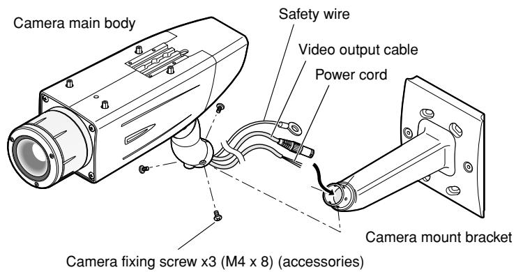
- Remove the screw from the mounting boss for safety wire of the camera mount bracket and secure the safety wire with the screw.
Important:
- Ensure that the safety wire is firmly secured. Recommended tightening torque: 0.59 N·m
Important:
- To install this product outdoors, be sure to waterproof the cables. The camera main body is waterproof, but the mount bracket and adapter box are not waterproof.
- To install this product outdoors, use waterproof silicon rubber or the like to apply waterproof treatment to the camera mount bracket, adapter box, cable access hole, screw holes, and screws.
- To install this product on a wall, face the drain slit of the camera mount bracket downward. Do not block the drain slit. Do not waterproof the drain slit, either.
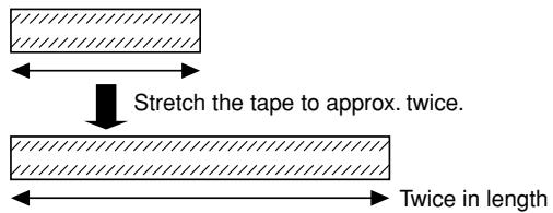
- Be sure to use the supplied waterproof tape at the connection parts of the power cord and video output cable to apply waterproof treatment.
- Stretch the tape by approx. twice (see the illustration at right) and wind it around the cables. Insufficient tape stretch causes insufficient waterproofing.
- Wind the cable with tape in a half-overlapping manner.
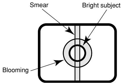
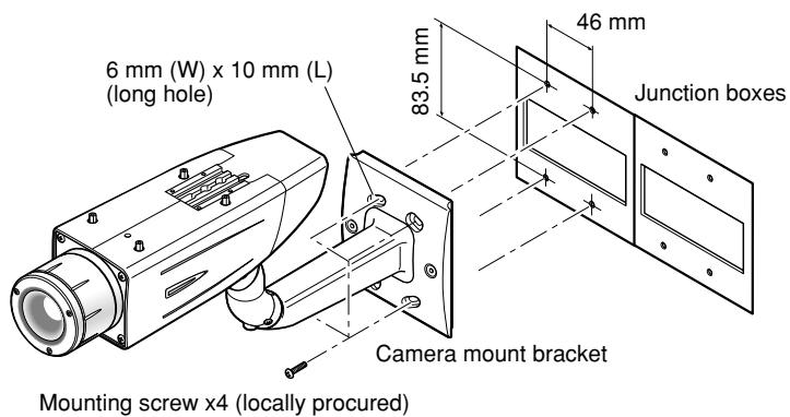
2 Secure the camera mount bracket
- When the camera is directly installed on a wall
Use 4 screws (locally procured) to secure the camera mount bracket to a wall or a junction box (locally procured).
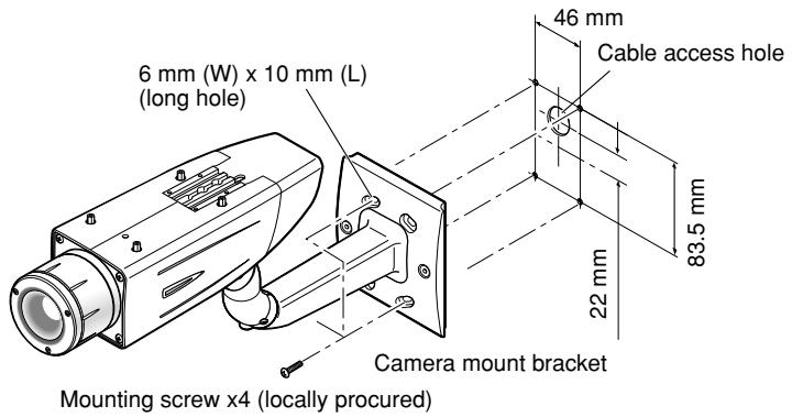
If a junction box is used, putting the boxes side by side is recommended as shown in the illustration at right. (for easy cable passing)
- When the camera is installed on a wall using the adapter box
- Use 4 screws (locally procured) to secure the adapter box to a wall or a junction box (locally procured).
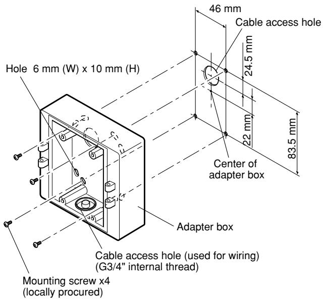
- If a junction box is used, putting the boxes side by side is recommended as shown in the illustration at right. (for easy cable passing)
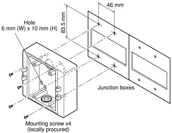
- Attach the camera mount bracket to the left or right hinges of adapter box.
Adaptor box mounting screw (M4 x 35)
Mounting screw for adapter box/camera mount bracket x4 (M5 x 20)
Note:
- The right or left hinges of the adapter box shall be selected so as to prevent the motion of the camera mount bracket from being interfered with by obstructions such as a wall when the camera mount bracket is connected to the hinges of the adapter box.
3 Secure the mount bracket covers to the camera mount bracket with the 2 mount bracket cover screws (accessories).
natural_image
Technical line drawing of a surveillance camera connected to an open electrical enclosure (no text or symbols present)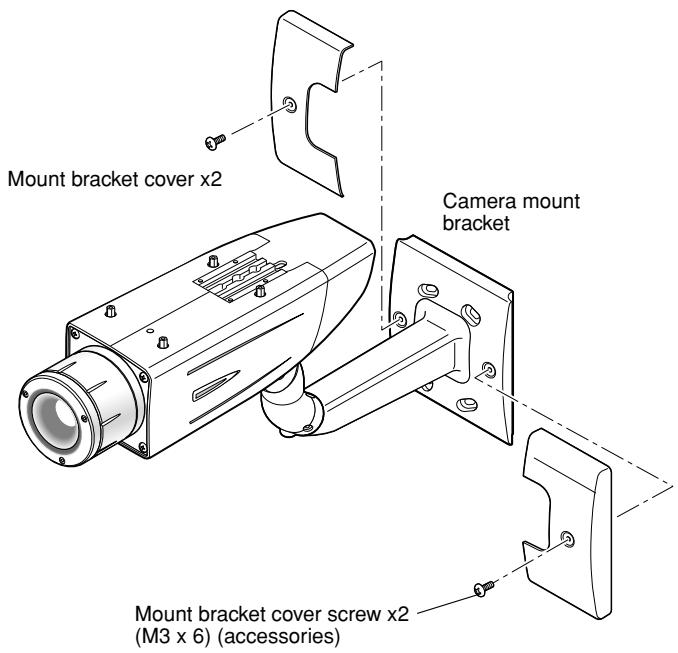
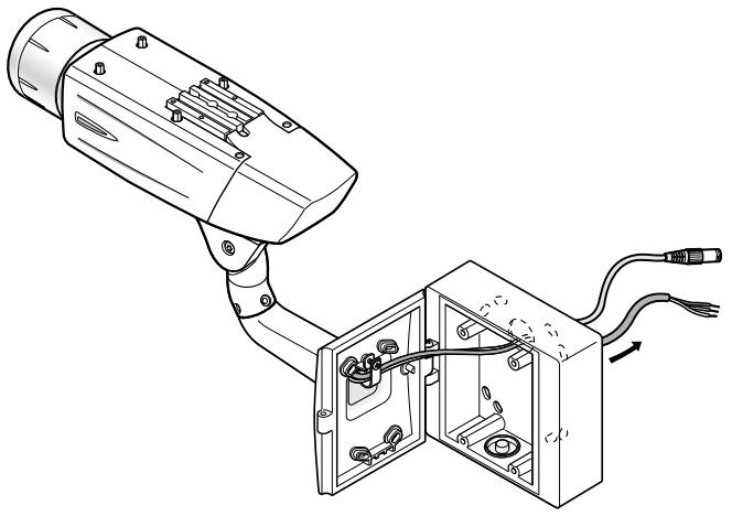
4 Make a connection
Video output connection
The video output connector is connected to the monitor or other system devices with a coaxial cable (locally procured).
The maximum extensible length is shown in the table.
| Type of coaxial cable | RG-59/U(3C-2V) | RG-6/U(5C-2V) | RG-11/U(7C-2V) | RG-15/U(10C-2V) | |
| Recommended maximum cable length | m | 250 | 500 | 600 | 800 |
Power connection
Caution:
- The following connections should be made by qualified service personnel or system installers in accordance with NEC 725-51.
- Wire colors & functions
Camera power cord
| Wire Color | 24 V AC | 12 V DC |
| Brown | 24 V AC (L) | Positive |
| Blue | 24 V AC (N) | Negative |
| Green/Yellow | To GND | To GND |
| Wire Color | |
| Brown | 220 V to 240 V AC (L) |
| Blue | 220 V to 240 V AC (N) |
| Green/Yellow | To GND |
Cautions:
- Be sure to connect the GND (grounding) lead of the camera and grounding terminal of the power supply when using a 24 V AC (WV-CW384) or 220 V to 240 V AC (WV-CW380) power source.
-
Shrinking the cord-entry seal is a onetime procedure. Do not shrink the cord-entry seal until it has been ascertained that unit is functioning.
-
ONLY CONNECT THIS TO 24 V AC or 12 V DC CLASS 2 POWER SUPPLY.
- To prevent fire or electric shock hazard, the UL listed wire VW-1 style 1007 should be used for the cord for Input Terminals.
- Do not use a transformer larger than 10 VA.
Cord length and wire gauge
24 V AC
The recommended cord length and copper wire size are shown in the table for reference.
The voltage supplied to the camera should be between 19.5 V AC and 28 V AC.
Recommended wire gauge for 24 V AC line.
| Copper wire size (AWG) | #24(0.22 mm2) | #22(0.33 mm2) | #20(0.52 mm2) | #18(0.83 mm2) | |
| Wire length (Approx.) | m | 20 | 30 | 45 | 75 |
12 V DC
The recommended resistance and copper wire size are shown in the table for reference.
The voltage supplied to the camera should be between 10.5 V DC and 16 V DC.
Resistance of copper wire [at 20°C]
| Copper wire size (AWG) | #24(0.22 mm2) | #22(0.33 mm2) | #20(0.52 mm2) | #18(0.83 mm2) |
| Resistance (Ω/m) | 0.078 | 0.050 | 0.03 | 0.018 |
"L", "R", "V_A", and "I" shall satisfy the inequality below.
10.5 V DC ≤ VA - 2(R × I × L) ≤ 16 V DC
L : Cord length (m)
R : Resistance of copper wire ( /m )
V_A : DC output voltage of power supply unit
I : DC current consumption (A). See the specification.
Important:
- When using 12 V DC power supply, the heater is unavailable.
5 Be sure to view the monitor for adjustment when the camera angle is adjusted.
Supply power to this unit, connect the monitor for adjustment (e.g. a small LCD) to the monitor output jack, and adjust the camera angle (turn off the power after view angle adjustment for safety).
- Loosen the 4 fixing screws of the lens cover to remove the lens cover.
- Connect the monitor for adjustment to the monitor output jack.
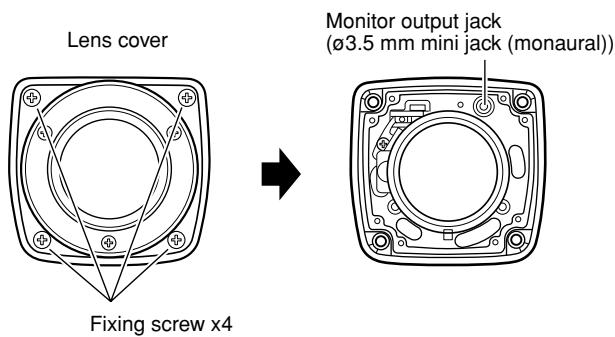
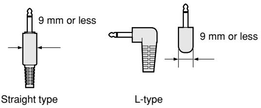
Note:
- The plug dimensions in the illustration below shall be observed for the monitor for adjustment.
- Repeat the steps (1) and (2) to adjust the camera angle.
(1) Loosen the panning lock screw and rotate the camera head horizontally to adjust panning.
(2) Loosen the tilting lock screw and rotate the camera head vertically to adjust tilting.
(3) Tighten the panning lock screw and tilting lock screw after camera angle adjustment.

Important:
- After camera angle adjustment, the panning lock screw and tilting lock screw shall be securely tightened.
Recommended tightening torque: 2.45 N·m
Notes:
- Use a hexagonal wrench with width across flats of 4 mm (locally procured) to loosen or tighten the panning lock screw and tilting lock screw.
- Approximately 1 rotation of loosening the panning lock screw and tilting lock screw allows camera angle adjustment. Do not loosen the screws beyond necessity.
- The camera body shall be held when the panning lock screw or tilting lock screw is loosened.
- Focus adjustment ( page 16) shall be performed when panning and tilting adjustments are performed.
6 Adjust the focus
Focus adjustment must be performed when camera angle ( page 15) adjustment are performed.
- Repeat the steps (1) and (2) to adjust the view angle and focus.
(1) Rotate the zoom adjustment ring to adjust the view angle between TELE and WIDE.
(2) Loosen the focus lock knob, make coarse adjustment of the focus, and then tighten the focus lock knob.
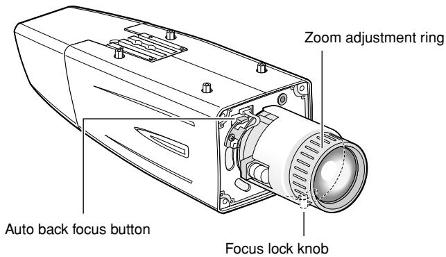
- Press the auto back focus button after adjusting the view angle while viewing the monitor for adjustment.
→ The focus position indicator is displayed in the lower part of the screen, and the back focus is automatically adjusted.
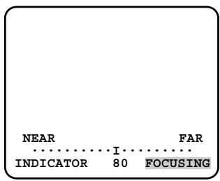
- To perform fine adjustment of the back focus after automatic back focus adjustment, use the operation buttons through the setup menu. ( page 31)
Notes:
- No operation for 10 seconds or more automatically clears the focus position indicator.
- To change the angle of view by moving the zoom adjustment ring, also move the focus lock knob to adjust the focus.
- When an auto iris lens is used to shoot a photographic subject, the originally adjusted focus may be slightly off depending on the iris state resulting from the focal depth of the lens. In such a case, open the aperture by darkening the subject as much as possible in the same way of taking picture, and then adjust the focus. Defocus can be prevented.
Use of "ABF" of "BACK-FOCUS SETUP" in the setup menu ( page 31) allows users to adjust the focus optimally in the range of the capability to automatically follow the variation in illuminance. (Note: The adjusted focal point is not necessarily the same as the optimal focal point at the illuminance.)
- The out-of-focus level in the near-infrared light region may be higher than that in the visible light region.
Setting "C/L ←→ B/W" of "BACK-FOCUS SETUP" to "AUTO" or "PRESET" in the setup menu allows users to adjust the focus in both the near-infrared light and visible light regions. (The variation in illuminance is not followed after focus adjustment.)
- Reset the back focus position to restore the default position before the back focus adjustment. (Hold down the right and left buttons among the operation buttons simultaneously for 2 seconds or more, or move the cursor to "MANUAL-ADJ" of "BACK-FOCUS SETUP" in the setup menu and hold down the right and left buttons simultaneously for 2 seconds or more after pressing the setting button.)
- Loosen the 1 fixing screw of the rear cover to remove the rear cover.
- Loosen the 2 fixing screws of the switch cover to remove the switch cover.
- Hold down the setting button for 2 seconds or more to call up the top screen of the setup menu. And then adjust the back focus. For further information, refer to page 31.
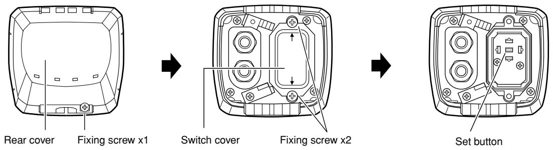
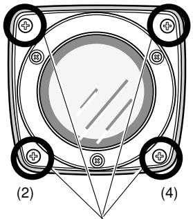
7 Mount the cover
- Attach the desiccant (accessory) to the inner bottom side of the lens cover.
- Mount the lens cover, switch cover, and rear cover.
Mouning lens cover
(3) (1)
natural_image
Pure diagram of a circular component with four labeled points and connecting lines, no text or symbols present.Fixing screw x4
Mouning switch cover
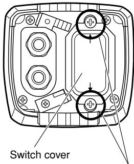
Fixing screw x2
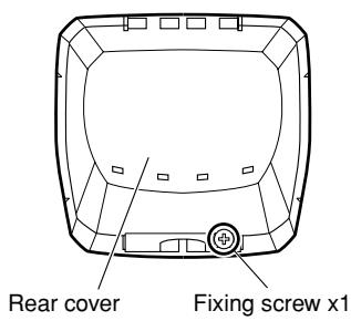
Mouning rear cover
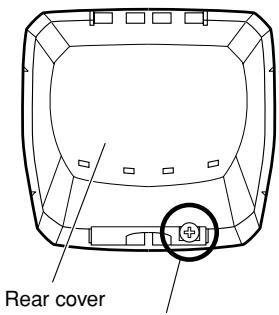
Fixing screw x1
Important:
- The tightening torque described below shall be followed for the 2 fixing screws of switch cover and the 4 fixing screws of lens cover.
Recommended tightening torque: 0.59 N·m
- Be sure to attach the desiccant (accessory). Refer to the instructions for the desiccant for how to attach it.
- The tightening sequence of the 4 fixing screws of the lens cover shall be observed and repeated twice as described in the illustration above.
$$ ((1) \rightarrow (2) \rightarrow (3) \rightarrow (4), \text { twice }) $$
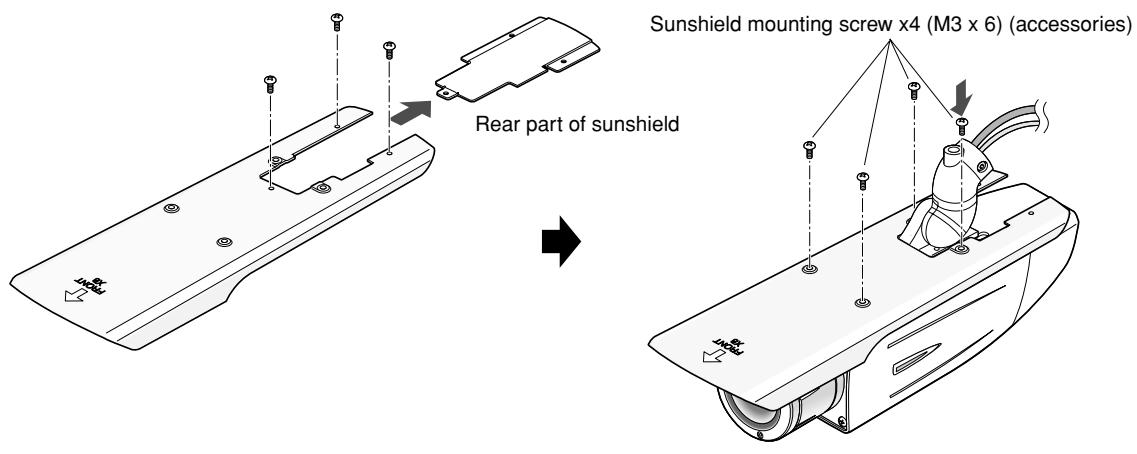
8 Mount the sunshield
Mount the sunshield on the camera with the 4 sunshield mounting screws (accessories).
Sunshield mounting screw x4 (M3 x 6) (accessories)
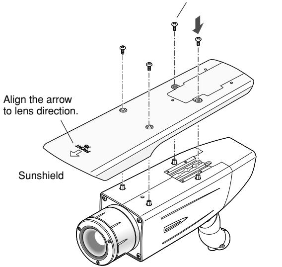
Camera main body
Notes:
- Be sure to use the 4 sunshield mounting screws (accessories). Recommended tightening torque: 0.59 ~N · m
- The "FRONT" side of the sunshield shall be on the lens side.
9 When the mounting surface is changed to the top surface of the camera body
- Remove the 4 tripod head fixing screws from the camera body and remove the tripod head.
- Loosen the spacer fixing screw of the tripod head and remove the spacer.
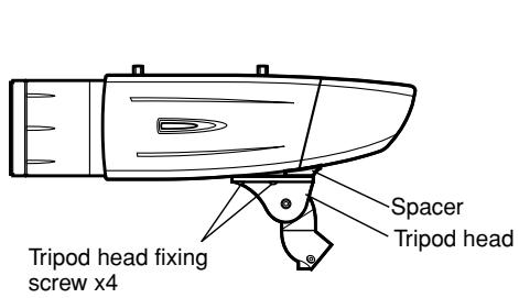
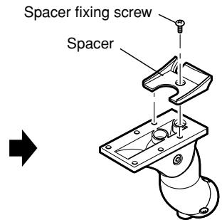
-
Loosen the fixing screw and remove the rear cover.
-
Position the cable clamp topside to pass the video output cable and power cord upward. And then, mount the rear cover.
- Mount the tripod head on the top of the camera body with the 4 tripod head mounting screws that were removed in the step 1.
Important:
- Caution shall be taken to prevent the video output cable and power cord from being caught between the camera body and tripod head.
- Secure the camera to the camera mount bracket with the 3 camera fixing screws (accessories).
Pass the video output cable, and power cord and safety wire through the camera mount bracket and secure the safety wire to the camera mount bracket.
Important:
- Be sure to use the screws that were removed from the tripod head.
Recommended tightening torque: 0.59 N·m
- Mount the sunshield on the camera body with the 4 sunshield mounting screws (accessories) after removing the sunshield backside.
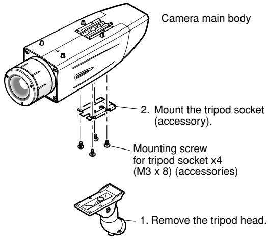
10 When the tripod socket (accessory) is used (when a different camera mount bracket is used)
- Remove the 4 tripod head fixing screws from the camera body and remove the tripod head. Disassemble the tripod head and pull out the video output cable and power cord.
- Mount the tripod socket (accessory) with the 4 mounting screws for tripod socket (accessories).
- Use a safety wire (locally procured) to take measures against a fall of the camera according to the installation position.
| Camera mount bracket | Safety wire | |
| For wall installation | WV-831 | WV-Q140 |
| For ceiling installation | WV-7010A | WV-Q141 |
- Hook the tip (ring portion) of the safety wire on the sunshield mounting stud and screw the sunshield to secure the safety wire.
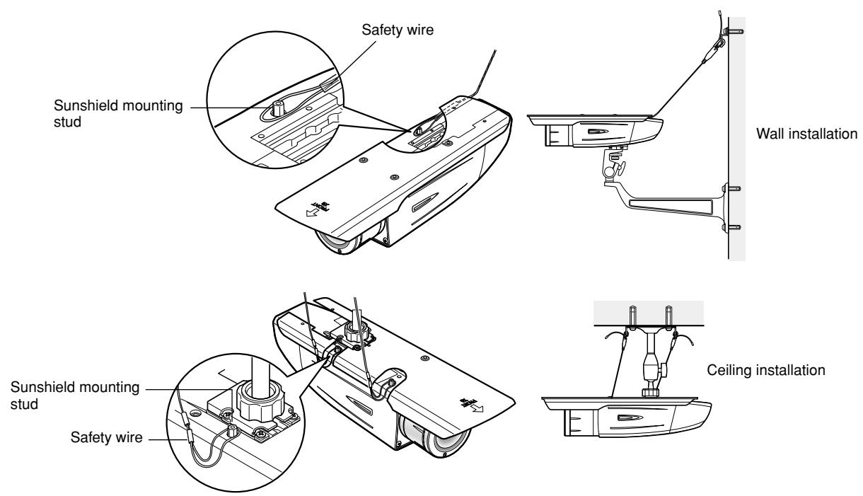
- Refer to the instructions of the safety wire for the following steps.
Important:
- Be sure to use the 4 mounting screws for tripod socket (accessories).
Use of screws with inappropriate length may damage the unit. - The 4 screws removed from the tripod head cannot be used.
- The camera mount brackets, WV-831 and WV-7010A, and the safety wires, WV-Q140 and WV-Q141, are designed to be used indoors. For outdoor installation, use the camera mount bracket in the accessories.
About Setup Menus
Before operation, setup of this camera is required. On the setup menu, you can check current settings and perform settings to meet requirements.
The following is an example of setup procedure when "LANGUAGE" is set to "ENGLISH".
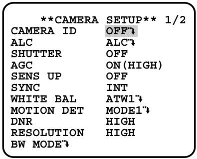
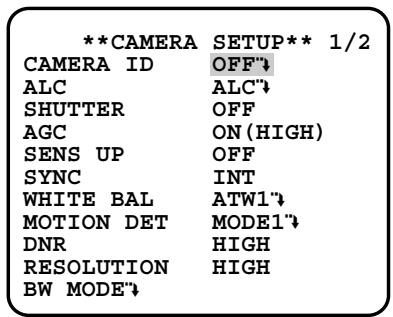
Settings items of the camera setup page
| Setup item | Description | Reference Pages |
| CAMERA | Configure the settings relating to camera operations | |
| CAMERA ID | The camera title can be edited and displayed on the screen. | 23 |
| ALC | Configure the light control method. | 24 |
| SHUTTER | Select the shutter speed. | 25 |
| AGC | Select the method of the gain adjustment. | 26 |
| SENS UP | Adjust the sensitivity. | 26 |
| SYNC | Configure the method of the synchronization. | 26 |
| WHITE BAL | Select the method of the white balance adjustment. | 27 |
| MOTION DET | Configure the settings for the motion detection function. | 27 |
| DNR | Configure the settings for the DNR (Digital Noise Reduction) function. | 29 |
| RESOLUTION | Select a horizontal resolution mode. | 29 |
| BW MODE | Configure the settings relating to the BW mode such as the settings for switching between the color mode and the BW mode. | 29 |
| PRIVACY ZONE | It is possible to mask a designated zone and as a privacy zone. | 30 |
| EL-ZOOM | Adjust the electronic zoom. | 30 |
| STABILIZER | Select "ON" or "OFF" to determine whether or not to use the image stabilizer to prevent shaky images. | 31 |
| LED | Performs the settings for LED. | 31 |
| BACK-FOCUS | Select the method of the flange-back (back focal) length adjustment and adjust the flange-back (back focal) length minutely. | 31 |
| SPECIAL | 32 | |
| CHROMA GAIN | Adjust the chroma level (color density). | 32 |
| AP GAIN | Adjust the aperture level. | 32 |
| PEDESTAL | Adjust the pedestal level (brightness). | 32 |
| PIX OFF | Correct image defects such as scratches. | 32 |
| CAMERA RESET | Reset the settings of setup menu to the default settings. | 33 |
| SER.NO. | Check the serial number of this camera. | 33 |
| LANGUAGE | Select the language to display the setup menu. | 23 |
■ Basic operation
The following are descriptions of how to configure each setup item using the operation buttons (refer to page 8) on the camera. Setup using an optional system controller is also available.
Note:
- The illustrations below are the examples to be displayed on a video monitor.
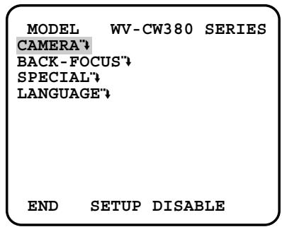
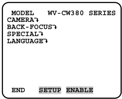
- Hold down the [SET] button for around 2 seconds.
→ The top page will be displayed. - Move the cursor onto "END" by press the [UP] or [DOWN] button.
-
Press the [SET] button after moving the cursor onto "SETUP" by pressing the [RIGHT] button.
→ The "DISABLE" indication will change into "ENABLE" and the settings will become editable. -
Move the cursor onto the desired setup item and press the [SET] button.
→ The setup page of the selected setup item will be displayed.
- Configure the settings for each item.
Select setup item: Move the cursor by pressing the [UP] or [DOWN] button.
Change the parameter: Press the [LEFT] or [RIGHT] button.
Display the detailed settings page of the setup item: Press the [SET] button when the setup item with the [""] mark is selected.
Go back to the previous page: Move the cursor onto "RET" and press the [SET] button.
Go back to the top page: Move the cursor onto "TOP" and press the [SET] button.
- To exit from the SETUP menu and display images from the camera, move the cursor onto "END" and press the [SET] button.
Notes:
- To prevent erroneous operations, the "DISABLE" indication will always be displayed when the top page is displayed from the camera. To operate the SETUP menu, switch the "DISABLE" indication to the "ENABLE" indication first.
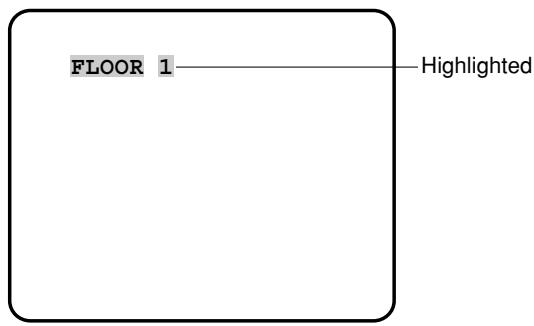
- The cursor position will be displayed highlighted.
First, select a language for menu display and camera ID display.
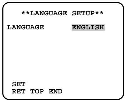
Language Setup (LANGUAGE SETUP)
- Select "LANGUAGE" on the top menu and press the [SET] button. → The "LANGUAGE SETUP" menu opens.
- Select a language. The default setting is "ENGLISH".
Available languages: ENGLISH, FRANÇAIS, ESPAÑOL, DEUTSCH, ITALIANO, РУССКИЙ, CHINESE or JAPANESE - Select "SET" on the menu and press the [SET] button.
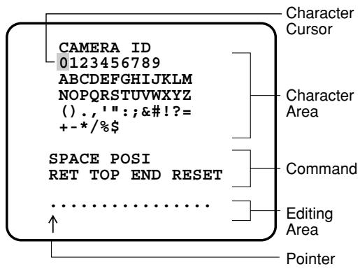
1. Camera Identification Setting (CAMERA ID)
Assign a name to the camera using up to 16 characters to display it overlaying on the camera picture in the selected position.
Note:
- If you change the language selection after the assignment of camera ID, it will be erased.
-
On the "CAMERA SETUP" menu, select "ON" or "OFF" for "CAMERA ID" and press the [SET] button.
ON"↓: Displays entered camera ID.
OFF": Does not display the ID.
→ The "CAMERA ID" menu opens. -
Select a character from the character area and press the [SET] button.
→ The selected characters are displayed in the editing area.
- Repeat these procedures until all characters are entered.
- To enter a blank space, select "SPACE" and press the [SET] button.
- To replace a specific character in the editing area:
-
Move the cursor to the editing area and then move the pointer to the character to be replaced pressing the [LEFT] and [RIGHT] buttons.
-
Move the cursor to a candidate character in the character area and press the [SET] button.
- To erase all characters of the camera ID, select "RESET" and press the [SET] button.
Note:
- For Chinese language, up to 8 characters can be entered.
-
To specify the ID display position:
-
Select "POSI" and press the [SET] button.
→ The entered camera ID will be highlighted on the screen. - Move it into the appropriate position and press the [SET] button.
→ The position is determined and the screen will return to the "CAMERA ID" menu.
Note:
- Keep pressing any of [LEFT], [RIGHT], [UP], or [DOWN] button for a second or more to move the camera ID faster as necessary.
2. Light Control Mode Setting (ALC)
Select a light control mode depending on the lens type mounted.
ALC"↓: Is applicable to the auto iris lens. "SUPER-D3" is available with this selection.
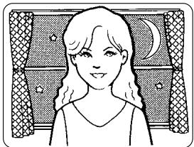
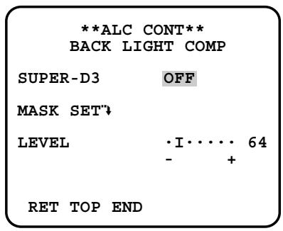
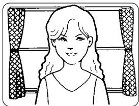
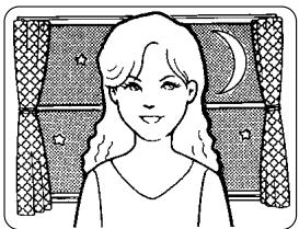
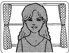
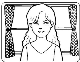
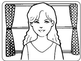
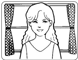
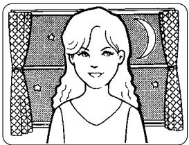
2-1. ALC Mode with SUPER-D3 ON
Super Dynamic 3 Function (SUPER-D3)
In the SUPER-D3 mode, more photometric weight is given to the center of the screen than to the edge where a bright backlight would most likely be located.
SUPER-D3 ON
natural_image
Illustration of a woman with long hair and a crescent moon, framed by decorative panels (no text or symbols)Nighttime

natural_image
Simple line drawing of a woman with long hair and a patterned curtain background (no text or symbols)Daytime
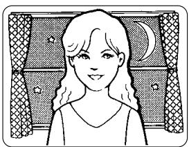
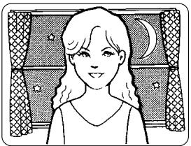
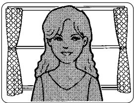
SUPER-D3 OFF
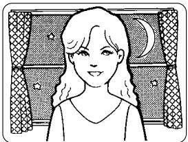
natural_image
Illustration of a girl with long hair and crescent moon, framed by a patterned curtain background (no text or symbols)Nighttime

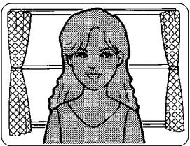
natural_image
Illustration of a person with long hair and a bow, framed by decorative curtains (no text or symbols)Daytime
SUPER-D3 ON: Enables SUPER-D3 to compensate backlight automatically.
SUPER-D3 OFF: Enables manual setting to compensate backlight.
Notes:
- When set to "ON", the available parameters for "SHUTTER" and "SENS UP" will be limited as shown on the next page.
-
Set "SUPER-D3" to "OFF" when noise in a bright portion, flickerings, or color deterioration are observed.
-
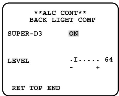
Move the cursor to "ALC" and press the [SET] button.
→ The "ALC CONT" menu opens. - Select "ON" for "SUPER-D3".
- Adjust the video output level (LEVEL) by moving the "I" cursor. It may be better to adjust "LEVEL" slightly higher.
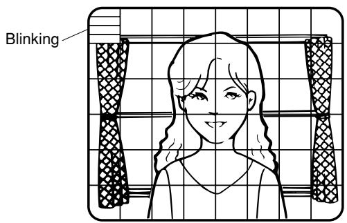
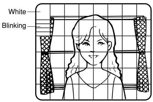
2-2. ALC Mode with SUPER-D3 OFF
-
Move the cursor to "ALC" on the "CAMERA SETUP" menu and select "OFF" for "SUPER-D3" on the "ALC CONT" menu.
→ "MASK SET" appears on the "ALC CONT" menu. -
Select "MASK SET" and press the [SET] button.
→ The 48 mask areas appear overlaid on the camera picture with the blinking cursor in the upper left corner.
- Move the cursor to an area where the backlight is bright and press the [SET] button to mask the area.
→ The masked area appears alternately white and blinking when the cursor is on the area, or it turns white when the cursor is on other areas.
- To cancel masking, move the cursor to a masked area and press the [SET] button.
→ When masking of the area is cancelled, it changes from white to normal.
To cancel all the masking, press the [LEFT] and [RIGHT] buttons simultaneously for 2 seconds or more.
-
Repeat step 3 and 4 as necessary.
-
Press the [SET] button for 2 seconds or more.
→ The "ALC CONT" menu appears.
- Adjust the video output level (LEVEL) by moving "I" cursor.
Note:
- If "ON" is selected for "SUPER-D3", a shadow (black line) may appear at the boundary between the bright and the dim portions. This is a natural phenomenon and does not indicate trouble.
3. Shutter Speed Setting (SHUTTER)
Select a proper shutter speed when "ALC" is selected on the "CAMERA SETUP" menu. Selecting a faster speed will reduce blurring when objects quickly move. The default setting is "OFF".

Notes:
- Only "OFF" is available when "SUPER-D3" is set to "ON".
- When a faster speed is selected for the electronic shutter, the picture will generally become darker, and sometimes a smear (vertical stripes caused by bright objects) may appear.
4. Gain Control Setting (AGC)
Select an automatic gain control mode. This setting raises the gain and brightens the image under low light conditions. The default setting is "ON (HIGH)".
Available modes: ON (HIGH), ON (MID), ON (LOW), OFF
5. Electronic Sensitivity Enhancement (SENS UP)
Select a proper enhancement rate when the camera is set to ALC mode. The higher rate you select, the brighter the picture will be. The default setting is "OFF".
AUTO: Sets "AGC" to "ON" and adaptively raises the sensitivity up to the selected amplification rate, for example 10 times when set to "X10 AUTO".
FIX: Raises the sensitivity fixedly to the selected rate.
OFF: Does not raise the sensitivity.
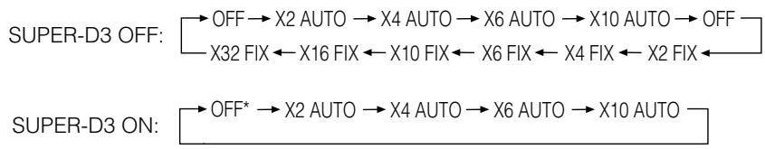
flowchart
graph LR
    A["SUPER-D3 OFF:"] --> B["OFF"] --> C["X2 AUTO"] --> D["X4 AUTO"] --> E["X6 AUTO"] --> F["X10 AUTO"] --> G["OFF"]
    A --> H["X32 FIX ← X16 FIX ← X10 FIX ← X6 FIX ← X4 FIX ← X2 FIX ←"]
    I["SUPER-D3 ON:"] --> J["OFF*"] --> K["X2 AUTO"] --> L["X4 AUTO"] --> M["X6 AUTO"] --> N["X10 AUTO"]
* Default
Notes:
- Some types of system controllers may not operate some of the SENS UP functions. If this happens, use the operation buttons on the camera.
- When you select "AUTO" for "SENS UP" and "ON" for "SUPER-D3", the SENS UP function has priority so that the SUPER-D3 function is not activated automatically.
- While the SENS UP function is selected, noise, spots or a whitish phenomenon may appear in the picture when the sensitivity of the camera is increased. This is a normal phenomenon.
- Only when "OFF", "X2 FIX", or "X2 AUTO" is selected for sensitivity enhancement (SENS UP), it is possible to perform ABF adjustment or to select "AUTO" for "C/L ←→ B/W" on the "BACK-FOCUS SETUP" menu. When a sensitivity rate other than "X2 FIX" or "X2 AUTO" is selected, use "PRESET" and "FIX" for "C/L ←→ B/W" on the "BACK-FOCUS SETUP" menu.
6. Synchronization Setting (SYNC)
1. Select a sync mode.
VD2: Multiplexed vertical drive, highest priority
LL: Line-Lock, follows the phase of supplied AC power, 2nd priority
INT: Internal sync, lowest priority
Notes:
- Selection is not available when VD2 is added to the camera. Selection from "LL" is available when the respective sync is added.
- When "LL" is selected, phase adjustment is required.
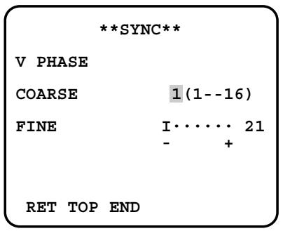
2. Line-Lock Vertical Phase Adjustment (V PHASE)
- Select "LL" and press the [SET] button.
- Prepare a dual-trace oscilloscope and supply it with the video output of the camera to be adjusted and that of the reference camera.
- Set the oscilloscope to the vertical rate and expand the V-sync portion.
- Select a proper "COARSE" phase from 16 steps (22.5 degrees/step) that makes the two video signals on the oscilloscope the closest.
- Select a proper "FINE" phase so that the two video signals on the oscilloscope come as close as possible.
Notes:
- Moving the "I" cursor across the +/- end will shift the "FINE" range.
- Press the [LEFT] and [RIGHT] buttons simultaneously to reset the "V PHASE" to the default (0 degree).
- Keep pressing the [LEFT] and [RIGHT] buttons for a second to move the "I" cursor faster if necessary.
- Spike noise if contained in the AC mains may disturb synchronization of LL.
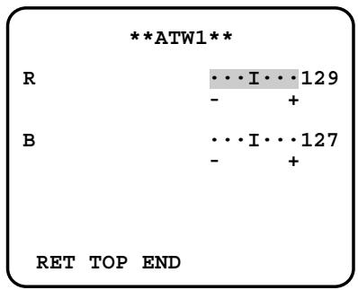
7. White Balance Setting (WHITE BAL)
Select a mode for "WHITE BAL" on the "CAMERA SETUP" menu. The default setting is "ATW1".
ATW1: Is automatically adaptable to the color temperatures of 2 700 K - 6 000 K.
ATW2: Is automatically adaptable to the use of sodium lamps (2 000 K - 6 000 K).
AWC: Is automatically adaptable to the color temperatures of 2 000 K - 10 000 K.
Notes:
- When "ATW1" or "ATW2" is selected, no further operation is required.
- "ATW1" and "ATW2" do not appear on the setup menu of the system controller.
- Select "AWC" in the following cases: the color temperature is out of the 2 000 K - 6 000 K range, the scene contains mostly high color temperatures such as blue sky or sunset, or the scene is dim.
- When "AWC" is selected, the "AWC" setting is required.
AWC Setting
- Select "AWC" and press the [LEFT] button.
→ "AWC" will change to "AWC → PUSH SW". - Press the [SET] button.
→ "PUSH SW" will be highlighted while the "AWC" setting is performed.
Note:
- If the white balance is not set, "PUSH SW" is being highlighted.
- Press the [RIGHT] button.
Manual Fine Adjustment
Perform fine adjustment as necessary.
- Select "WHITE BAL" and press the [SET] button.
→ Fine adjustment menu of ATW or AWC will open. - Adjust finely "R" (Red) and "B" (Blue) gain by moving the "I" cursor.
8. Motion Detection Setting (MOTION DET)
When a series of changes in pictures is detected, the camera outputs an alarm to the external device such as a disk recorder. The recorder will start recording the pictures.
- Select a mode for "MOTION DET" on the "CAMERA SETUP" menu.
The default setting is "OFF".
OFF: Disables the alarm output.
MODE1: Outputs alarm when a series of motions is detected.
MODE2: Outputs alarm when a series of scene changes is detected.
→ The "MODE1" menu opens when you select "MODE1" and press the [SET] button.
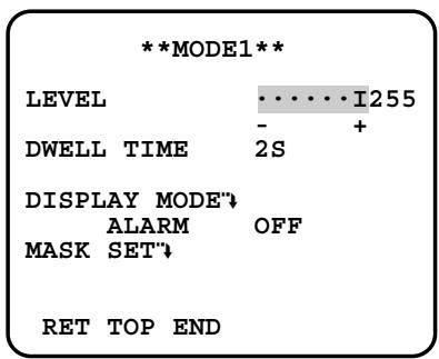
-
Adjust for "LEVEL" to optimize the sensitivity of detection.
-
Select a dwell time. The default setting is "2S".
Available time (second): 2, 5, 10, 30
The next detection will be performed after the set time elapses.
- Select "MASK SET" and press the [SET] button.
→ A 48-split screen opens.
- Specify non-detection (mask) and detection areas in the same way as described earlier in 2-2 ALC Mode. ( page 25)
- Hold down the [SET] button for 2 seconds to return to the "MODE1" menu.
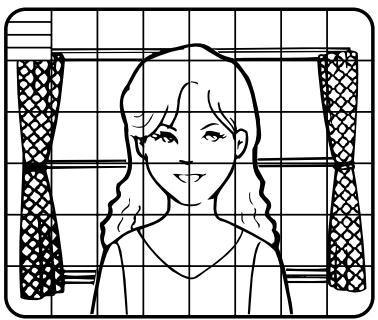
natural_image
Line drawing of a woman with long hair and a patterned garment, viewed from behind a grid background (no text or symbols)Note:
- Perform the setting of mask area after "STABILIZER" in the "CAMERA SETUP" menu is set to "OFF".
- Select "ON" or "OFF" for "ALARM" under "DISPLAY MODE".
ON: Outputs an alarm
OFF: Does not output an alarm. This is applicable any of the following controllers are used: WV-RM70, WV-CU550 series, WV-CU161, WV-CU360, WV-CU650, WV-CU850, WV-CU950
- Select "DISPLAY MODE" and press the [SET] button to see the current settings.
When a motion is detected, the area will blink.
- Press the [SET] button to return to the "MODE1" menu.
- As necessary, repeat to perform "LEVEL" adjustment and "MASK SET" setting by checking on the "DISPLAY MODE" screen.
Important:
- In systems other than Panasonic, select "OFF" for "MOTION DET" to prevent system devices from confusing time-code signal with alarm signal.
- Set "MASK SET" over the areas where leaves or curtains etc. are swaying.
- Adjust the detection level to prevent detection from confusing motion with noise under low light conditions.
- It takes around 0.2 seconds for the alarm signal to reach the VTR's alarm terminal after detection.
- The motion/scene change detection is not specifically intended to prevent theft or fire.
Motion Detector
The motion detector divides the screen into 48 blocks and monitors changes in the luminance in each block. When it detects any change (movement) in the image, it outputs an alarm signal. When a change (movement) in the image is detected while in the auto mode, the alarm signal is output and the camera stops at the preset position for a specified amount of time.
Demo Mode
The demo mode divides the screen into 48 blocks and monitors changes in the luminance in each block. It also masks any part of the picture where there is a change in average luminance that exceeds the currently specified detection sensitivity level. The demo mode results can be used to determine the optimum detection sensitivity level (step 2) and the areas of the screen that need to be masked (step 4).
About MODE2 of Motion Detection
The camera will detect a scene change in the following cases.
When the lens is fully sprayed or covered with a cloth, lid, or the like
When the camera direction is suddenly changed
Important:
- The camera will not detect a scene change in the following cases.
When a cloth with patterns covers the lens and it sways in the wind
When some portions in the screen are not veiled
When the screens are similar in scene patterns although the camera direction has changed
- The camera will faultily detect a scene change in the following cases.
When an obvious brightness change arises (ex. On/Off of the lamps)
When objects move continuously such as traffic in busy streets
9. Digital Noise Reduction Setting (DNR)
Select a "DNR" mode suitable to the camera site conditions. The default setting is "HIGH".
HIGH: Greatly reduces noise, though it produces afterimages when objects move.
LOW: Slightly reduces noise, and produces less afterimages.
10. Resolution Setting (RESOLUTION)
Select a horizontal resolution mode. The default setting is "HIGH".
NORMAL: Resolves more than 480 TV lines.
HIGH: Resolves typically 540 TV lines, though noise may increase when "SENSE UP" is activated in low lighting conditions.
11. Black and White Mode Setting (BW MODE)
- Select "BW MODE" on the "CAMERA SETUP" menu and press the [SET] button.
→ The "BW MODE" menu opens.
- Select a mode for "BW". The default setting is "OFF".
→ When "AUTO1" or "AUTO2" is selected, "LEVEL" and "DURATION TIME" appear.
AUTO1: Sets the mode to black-and-white if the picture is dark or to color if the picture is bright enough.
AUTO2: Functions the same as "AUTO1", except this is applied to the use near infrared light. (wavelength ≥ 800 nm).
ON: Sets the mode to black-and-white.
OFF: Sets the mode to color.
Notes:
- There may be cases where "AUTO1" or "AUTO2" does not function well if the camera is aimed at subjects continuously moving or a scene filled with a single color such as a blue sky.
-
It is possible to set up the back-focus mode to compensate for defocus liable to happen when the camera automatically switches between the color and black-and-white modes. Refer to page 31. Back-focus Setting for details.
-
Select a threshold "LEVEL" to switch between the color and black-and-white mode. The default setting is "HIGH".
HIGH: Switches the mode at approx. 5 lx illumination.
LOW: Switches the mode at approx. 1 lx illumination.
- Select a duration time to determine whether to switch the mode. The default setting is 30 seconds.
Available time: (Short) 10 s ↔ 30 s ↔ 60 s ↔ 300 s (Long)
- Select a burst signal mode. The default setting is "ON".
ON: Supplies the (color) burst signal with black-and-white composite video.
OFF: Supplies no burst signal.

Note:
- Using "ON" is usually recommended. Try both "ON" and "OFF" to match to connected devices (recorders, monitors, etc.) that have different characteristics.
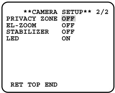
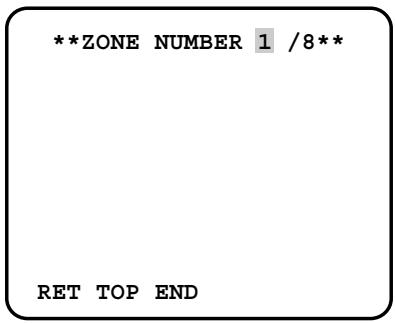
12. Privacy Zone Setting (PRIVACY ZONE)
Perform settings of up to eight privacy zones where you wish to veil the monitor screen.
- Select "ON(1)", "ON(2)" or "OFF" for "PRIVACY ZONE" on page 2 of the "CAMERA SETUP" menu and press the [SET] button. The default setting is "OFF".
ON (1): Veils the zone with grey.
ON (2): Veils the zone with mosaic.
OFF: Displays pictures normally.
→ The "ZONE NUMBER" selection menu opens.
- Select a zone number on the top line using the [LEFT] and [RIGHT] buttons and press the [SET] button. The zone number followed by an asterisk * indicates that it has been already registered.
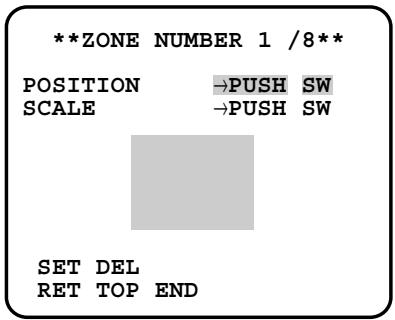
→ "POSITION", "SCALE", and a frame appear on the menu.
- Select "→PUSH SW" for "POSITION" and press the [SET] button.
→ Position selection becomes available.
-
Move the picture portion to be veiled to the center of the frame using the [LEFT], [RIGHT], [UP], or [DOWN] button.
-
Select "→PUSH SW" for "SCALE" and press the [SET] button.
→ Zone scale adjustment becomes available.
-
Adjust the zone scale using the [LEFT], [RIGHT], [UP], or [DOWN] button.
-
To apply the settings, move the cursor to "SET" and press the [SET] button.
→ The screen returns to the "ZONE NUMBER" selection menu.
To delete the settings, select "DEL" and press the [SET] button.
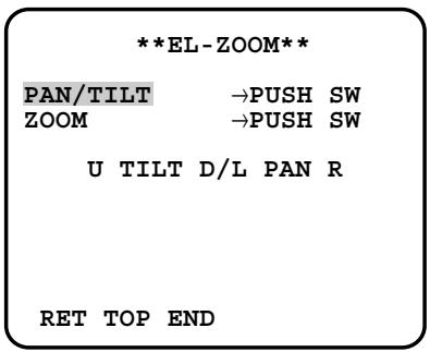
13. Electronic Zoom (EL-ZOOM)
-
Move the cursor to "EL-ZOOM".
-
Select "ON" or "OFF" by pressing [LEFT] and [RIGHT] buttons. The default setting is "OFF".
ON: x2 electronic zoom is available with the ZOOM switch on the controller.
OFF: The electronic zoom function is disabled.
-
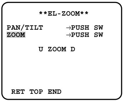
While the cursor is on "EL-ZOOM", press the [SET] button. The "EL-ZOOM" menu appears.
-
Move the cursor to "→PUSH SW" for "ZOOM" and press the [SET] button to display the "ZOOM" setting menu.
-
Press the [UP] or [DOWN] button to zoom in or out the image.
-
Move the cursor to "→PUSH SW" for "PAN/TILT" and press the [SET] button. The "PAN/TILT" setting menu appears.
-
Press [LEFT], [RIGHT], [UP], or [DOWN] button to change the angular field of view.
-
To return to the "EL-ZOOM" menu, press the [SET] button.
14. Auto Image Stabilizer (STABILIZER)
This function electronically compensates for an unstable camera image due to movement of a mounting pole or bracket. The default setting is "OFF".
ON: Automatically compensates for an unstable image.
OFF: Image stabilizer will not operate.
Important:
- When set to "ON", some effective pixels on the edge of the CCD are used by the stabilization function. This may result in a small reduction in resolution and a narrower angle of view. After activating the image stabilizer function, check that the field of view is correct.
- Image stabilization may not function where there is excessive camera movement or when the scene is low light or low contrast objects.
15. LED Setting (LED)
"ON" or "OFF" is selected to decide whether or not to use the LED located on the side of this unit. The default setting is "ON".
ON: Blinks the LED when the motion detector function ( FF page 27) detects a change in an image. Lights in the cases other than the above.
OFF: Keeps the LED unlit.
16. Back-focus Setting (BACK-FOCUS SETUP)
Perform adjustment of the back-focus (flange-back: the gap between the lens and focal plane) remotely on this menu using a
system controller. After installation, you can perform this adjustment when defocus arises that may be caused by long-term use, environmental changes, etc.
Important:
- Do not use the ABF function for continuous or repetitive purposes (ex. autofocus etc.). This function is to be used to correct defocus caused by switching between color and black - and - white when/after installing the camera.
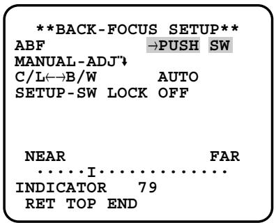
- Select "BACK-FOCUS" on the top menu and press the [SET] button.
→ The "BACK-FOCUS SETUP" menu opens.
- Select "ABF" and press the [SET] button.
→ Adjustment is automatically performed.
Notes:
- Performing ABF will function to obtain the best focus around the center areas in a scene.
- Performing ABF is available only when "OFF", "X2 AUTO", or "X2 FIX" is selected for "SENS UP".
-
Using the ABF function under low light conditions may cause noise.
-
Select "MANUAL-ADJ" and press the [SET] button if manual adjustment is required.
The manual back-focus adjustment screen will open.
- Use the [LEFT] or [RIGHT] buttons to move the "I" cursor and obtain a proper focus.
→ Refer to the 4-digit number on the second bottom line. The larger the number is, the better the focus will be. -
Select "RET" and press the [SET] button to go back to the menu setup.
-
Select a mode for "C/L ←→ B/W". The default setting is "AUTO".
AUTO: Adjusts the back-focus automatically every time the camera switches the mode between color and black-and-white. "AUTO" is usable only when "OFF", "X2 AUTO", or "X2 FIX" is selected for "SENS UP".
PRESET: Adjusts the back-focus to the positions for color mode and black-and-white mode that are preset by performing step 2 (automatic) or step 3 (manual) under the respective light conditions.
FIX: Fixes the back-focus after adjustment.
- Select "ON" or "OFF" for "SETUP-SW LOCK". The default setting is "OFF".
OFF: Enables the [SET] button to open the back-focus adjustment screen while the camera picture is displayed.
ON: Disables the [SET] button from opening the back-focus adjustment screen.
- To reset the back-focus to the default setting, press the [LEFT] and [RIGHT] buttons simultaneously.
Important:
- Select "FIX" or "PRESET" and adjust manually the back-focus when automatic adjustment is hindered by the following conditions.
- Dirt or a water drip attached to window glass This causes defocus on the object beyond the glass.
- Objects in low lighting conditions
- Objects extremely bright
- Flat contrast objects such as white wall or fine felt
- Objects placed on the outskirts of the scene
- More than one object placed with a certain depth
- An object having a certain depth
- Objects continuously moving such as busy streets
- Objects extremely flickering
- Objects consisting of parallel horizontal lines such as a window shade
- Panasonic Corporation shall not be responsible for any inconvenience, damage or loss caused by or attribute to inappropriate settings for the ABF function.
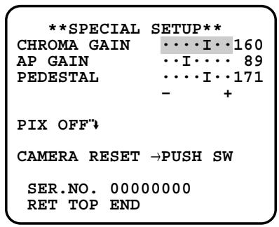
17. Special Menu (SPECIAL SETUP)
Select "SPECIAL" on the top menu and press the [SET] button.
→ The "SPECIAL SETUP" menu opens.
17-1. Chroma Level Setting (CHROMA GAIN)
Move the "I" cursor to adjust the chroma level.
17-2. Aperture Gain Setting (AP GAIN)
Move the "I" cursor to adjust the aperture gain level.
Lower the level when moire (a kind of noise, optical interference) appears on the screen as part of minute crosshatch pattern, etc.
17-3. Pedestal Level Setting (PEDESTAL)
Move the "l" cursor to adjust the pedestal level (black level).
17-4. Pixel Compensation Setting (PIX OFF)
Perform settings to compensate a maximum of 16 blemish pixels on the pickup device.
- Select "PIX OFF" and press the [SET] button.
→ The "PIX OFF" menu opens with numbers from 1 to 16. - Select a number and press the [SET] button.
→ The "PIX OFF" assignment screen opens with a + cursor.
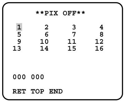
- Move the cursor to the center of a blemish position until its appearance becomes less obvious. Finally, press the [SET] button.
→ The horizontal and vertical positions (coordinate) of the blemish will be displayed with a 6-digit number on the second bottom line.
→ The blemish position is registered to be compensated.
→ The screen returns to the "PIX OFF" menu that displays the number followed by an asterisk if it has been registered.
natural_image
Empty rounded rectangle with a small plus sign in the center (no text or symbols beyond the plus)- Repeat above steps as necessary.
- To cancel a registration, select an asterisked number in the "PIX OFF" menu and press the [SET] button.
→ The "PIX OFF" assignment screen opens.
Hold down the the [LEFT] and [RIGHT] buttons simultaneously for 2 seconds or more.
→ The "PIX OFF" menu appears displaying the number without an asterisk if its registration has been cancelled.
17-5. To reset to the default settings (CAMERA RESET)
- Select "CAMERA RESET".
→ The "→PUSH SW" is highlighted. - While holding down the [LEFT] and [RIGHT] buttons, press the [SET] button for 2 seconds or more.
→ The camera will return to the default settings.
Note:
- "PIX OFF" setting cannot be initialized.
17-6. The serial number of the camera will be displayed. (SER. NO.)
Troubleshooting
Before asking for repairs, check the symptoms with the following table.
Contact your dealer if a problem cannot be solved even after checking and trying the solution in the table or a problem is not described below.
| Symptom | Cause/solution | Reference pages |
| No image displayed | Are the power cord and coaxial cable connected appropriately?→ Check whether the connection is appropriately established. | 14 |
| Is the monitor luminance appropriately adjusted, or is the contrast appropriately adjusted?→ Check whether the monitor settings are appropriate. | - | |
| Blurred image | Is the lens of the camera soiled with dirt or dust?→ Check whether the lens of the camera is clean. | - |
| Is the focus adjusted correctly?→ Check if the focus is adjusted correctly. | 16 | |
| Damaged power cord sheathing | The power cord is damaged.Use of the damaged cord may cause electric shock or fire.Turn off the power immediately and request repair to your dealer. | - |
| Heated portion of power cord during use. | ||
| Warmed power cord or loosened connection by bending or stretching during use. | ||
| LED not lit | Is power supplied to the camera?→ Check whether power is supplied to the camera. | - |
| Is "ON" selected for the LED setting?→ Check whether "ON" is selected for the LED setting. | 31 |
● Color CCTV Cameras
| Power source and power consumption: | WV-CW384: 24 V AC 50 Hz, 18 W, 12 V DC, 560 mAWV-CW380: 220 V to 240 V AC, 50 Hz, 14 W |
| Image sensor: | 1/3-inch type interline transfer CCD |
| Effective pixels: | 752 (H) x 582 (V) |
| Scanning area: | 4.8 mm (H) x 3.6 mm (V) |
| Scanning system: | 2:1 interlace |
| Scanning frequency: | Horizontal: 15.625 kHz, Vertical: 50.00 Hz |
| Synchronization: | Multiplexed vertical drive (VD2), line-lock (LL), internal (INT) |
| Resolution: | Horizontal: 570 TV lines (BW mode)540 TV lines typ., 520 TV lines min. (color mode, resolution: HIGH)Vertical: 400 TV lines (at center) |
| Minimum illumination: | Color mode:0.65 lx (sensitivity up OFF, AGC HIGH: F1.6, WIDE)0.065 lx (sensitivity up 10x, AGC HIGH: F1.6, WIDE)*BW mode:0.09 lx (sensitivity up OFF, AGC HIGH: F1.6, WIDE)0.009 lx (sensitivity up 10x, AGC HIGH: F1.6, WIDE)** Converted value |
| Signal-to-noise ratio: | 50 dB (AGC Off) |
| Dynamic range: | 54 dB typ |
| Video output: | 1.0 V[P-P] PAL composite/75 Ω, BNC connector |
| Monitor output: | 1.0 V[P-P] PAL composite/75 Ω, ø3.5 mm mini jack (monaural) |
| Functions | |
| Camera title: | Up to 16 characters (alphanumeric characters, marks) |
| Light control: | ALC |
| Super-Dynamic 3: | ON/OFF |
| Electronic shutter speed: | OFF (1/50), 1/120, 1/250, 1/500, 1/1 000, 1/2 000, 1/4 000, 1/10 000 |
| Gain control: | ON (HIGH)/ON (MID)/ON (LOW)/OFF |
| Sensitivity up: | OFF, X2 AUTO, X4 AUTO, X6 AUTO, X10 AUTO, X2 FIX, X4 FIX, X6 FIX, X10 FIX, X16 FIX, X32 FIX |
| Synchronization: | VD2/LL/INT |
| White balance: | ATW1/ATW2/AWC |
| Video motion detection: | MODE1/MODE2/OFF |
| Digital noise reduction: | HIGH/LOW |
| Resolution: | NORMAL/HIGH |
| Color/BW: | AUTO1/AUTO2/ON/OFF |
| Privacy zone: | ON(1)/ON(2)/OFF |
| Electronic zoom: | ON*/OFF (* Up to 2x) |
| Image stabilizer: | ON/OFF |
| LED: | ON/OFF |
| Back-focus: | ABF (AUTO/PRESET/FIX), MANUAL-ADJ |
| Special: | CHROMA GAIN, AP GAIN, PEDESTAL, PIX OFF |
| Language: | ENGLISH, FRANÇAIS, ESPAÑOL, DEUTSCH, ITALIANO, РУССКИЙ, CHINESE or JAPANESE |
| Ambient operating temperature: | -30 °C to +50 °C** -10 °C to +50 °C at 12 V DC |
| Ambient operating humidity: | 90% or less (no condensation) |
| Water resistance: | Camera: IEC60529 (IP66, Against ingress of water with harmful effects powerful jetting)** Applicable only when the installation and waterproof process are done properly. |
| Dimensions: | 82 (W) mm x 78 (H) mm x 301 (D) mm |
| Weight: | 1.5 kg |
| Finish: | Lens cover: Aluminum die cast with silver metallic coatingMain body: AES resin with silver metallic coating |
● Lens
| Focal length: | f=5 mm - 40 mm (8x variable focal lens) |
| F number: | F1.6 (WIDE) - F1.9 (TELE) |
| Focus range: | ∞ - 1.2 m |
| Angle of view: | Horizontal: 6.6° (TELE) - 52.0° (WIDE)Vertical: 5.0° (TELE) - 39.6° (WIDE) |
● Camera mount bracket
| Adjusting angle: | Panning range: ± 100^ |
| Tilting range: +30^ , -90^ | |
| Dimensions: | 125 (W) mm x 125 (H) mm x 143 (D) mm |
| Weight: | 240 g |
| Finish: | Aluminum die cast with silver metallic coating |
- Adapter box
| Dimensions: | 133 (W) mm x 133 (H) mm x 50 (D) mm |
| Weight: | 510 g |
| Finish: | Aluminium die cast with silver metallic coating |
Weights and dimensions indicated are approximate.
Standard Accessories
Operating Instructions (this document).... 1 pc.
| The following are for installation. | |
| Camera mount bracket | 1 pc. |
| Mount bracket cover | 2 pcs. |
| Sunshield | 1 pc. |
| Tripod socket | 1 pc. |
| Adapter box | 1 pc. |
| Camera fixing screws (M4 x 8) | 4 pcs. |
| (incl. 1 spare screw) | |
| Mount bracket cover screws (M3 x 6) | 3 pcs. |
| (incl. 1 spare screw) | |
| Adapter box mounting screw (M4 x 35) | 1 pc. |
| Mounting screws for adapter box/camera mount bracket (M5 x 20) | 5 pcs. |
| (incl. 1 spare screw) | |
| Sunshield mounting screws (M3 x 6) | 5 pcs. |
| (incl. 1 spare screw) | |
| Mounting screws for tripod socket (M3 x 8) | 4 pcs. |
| Desiccant | 1 pc. |
| Waterproof tape | 1 pc. |
Information on Disposal for Users of Waste Electrical & Electronic Equipment (private households)
This symbol on the products and/or accompanying documents means that used electrical and electronic products should not be mixed with general household waste.
For proper treatment, recovery and recycling, please take these products to designated collection points, where they will be accepted on a free of charge basis. Alternatively, in some countries you may be able to return your products to your local retailer upon the purchase of an equivalent new product.
Disposing of this product correctly will help to save valuable resources and prevent any potential negative effects on human health and the environment which could otherwise arise from inappropriate waste handling. Please contact your local authority
for further details of your nearest designated collection point.
Penalties may be applicable for incorrect disposal of this waste, in accordance with national legislation.
For business users in the European Union
If you wish to discard electrical and electronic equipment, please contact your dealer or supplier for further information.
Information on Disposal in other Countries outside the European Union
This symbol is only valid in the European Union.
If you wish to discard this product, please contact your local authorities or dealer and ask for the correct method of disposal.
DEUTSCHE AUSGABE
(GERMAN VERSION)
WARNUNG:
Installation/Anschlüsse 46
■ Vorbereitungen 46
natural_image
Symbolic illustration of a person climbing a ladder inside a circle with a diagonal line (no text or symbols)natural_image
Technical line drawing of a surveillance camera connected to an open electrical box (no text or symbols present)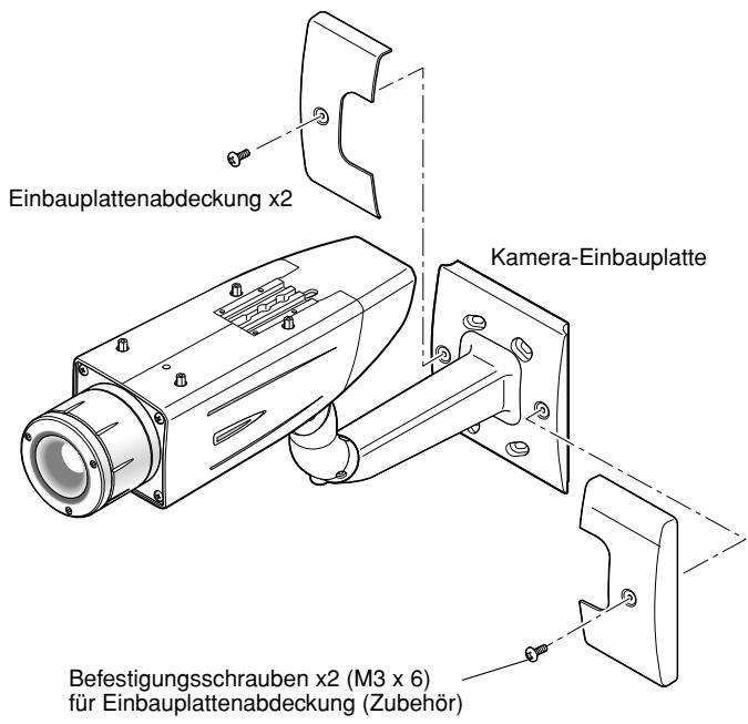
natural_image
Illustration of a woman with long hair and a crescent moon, framed by decorative panels (no text or symbols)Nachts
natural_image
Line drawing of a woman with long hair and a turtleneck, framed by decorative curtains (no text or symbols)Tags
SUPER-D3 AUS
natural_image
Illustration of a woman with long hair and crescent moon, framed by a window with star patterns (no text or symbols)Nachts
natural_image
Illustration of a woman with long hair and a bow, framed by decorative curtains (no text or symbols)Tags
natural_image
Line drawing of a woman with long hair standing on a grid background, framed by patterned curtains (no text or symbols)Hinweis:
natural_image
Empty rounded rectangle with a small plus sign in the center (no text or symbols beyond the plus)Horizontal: 6,6° (TELE) - 52,0 ° (WIDE)
Vertikal: 5,0° (TELE) - 39,6 ° (WIDE)
natural_image
Black and white icon of a person climbing a ladder with a diagonal line, no text or symbols present.natural_image
Technical line drawing of a surveillance camera connected to an open electrical enclosure (no text or symbols present)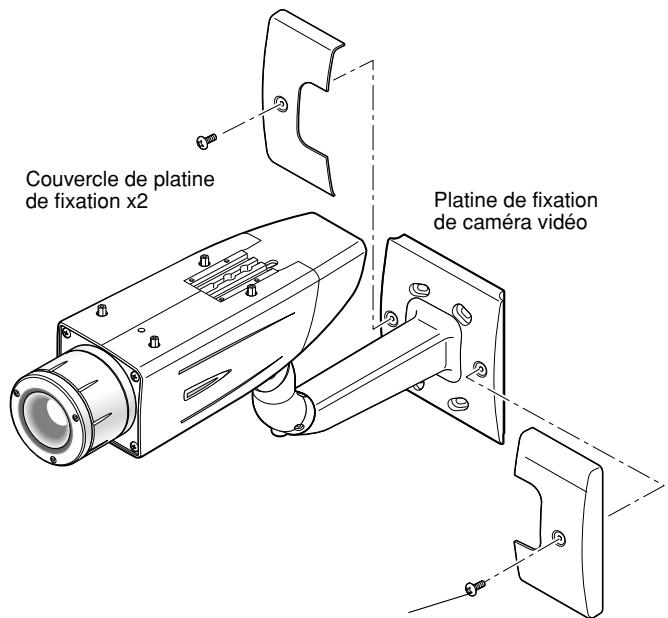
natural_image
Illustration of a woman with long hair and a crescent moon, framed by decorative curtains (no text or symbols)Heure de nuit
natural_image
Line drawing of a woman with long hair and a turtleneck, framed by decorative curtains (no text or symbols)Heure de jour
SUPER-D3 OFF
natural_image
Illustration of a woman with long hair and a crescent moon, framed by decorative curtains (no text or symbols)Heure de nuit

natural_image
Illustration of a person with long hair and a checkered garment, framed by a decorative frame (no text or symbols)Heure de jour
natural_image
Line drawing of a woman with long hair and a patterned garment, viewed from behind a grid background (no text or symbols)Remarque:
natural_image
Empty rounded rectangle with a small plus sign in the center (no text or symbols beyond the plus)WV-CW380: 220 V - 240 V c.a., 50 Hz, 14 W
GAIN CHROMA, CONTOURS, PEDESTAL, PIX OFF
ENGLISH, FRANÇAIS, ESPAÑOL, DEUTSCH, ITALIANO, РУССКИЙ, CHINESE ou JAPANESE
-30 °C à +50 °C*
Dimensions: 125 (L) mm x 125 (H) mm x 143 (P) mm
Poids: 240 g
Dimensions: 133 (L) mm x 133 (H) mm x 50 (P) mm
Poids: 510 g
natural_image
Symbolic illustration of a person pushing a large cart with a diagonal line, enclosed in a circle (no text or symbols)natural_image
Technical line drawing of a vehicle's internal components, including battery, fan, and wheel assembly (no text or labels)natural_image
Technical line drawing of a surveillance camera connected to an open electrical enclosure (no text or symbols present)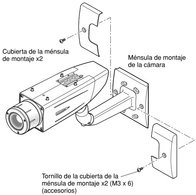
natural_image
Top-down schematic of a rectangular device with internal compartments and mounting points (no text or symbols)natural_image
Technical line drawing of a mechanical component with no visible text or symbolsnatural_image
Technical line drawing of a device rear panel with internal components and mounting holes (no text or symbols)Botón de ajuste
7 Monte la cubierta
natural_image
Illustration of a woman with long hair and a crescent moon, framed by patterned curtains (no text or symbols)Por la noche
natural_image
Simple line drawing of a woman with long hair and a V-neck top, framed by decorative panels (no text or symbols)Día
SD3 OFF
natural_image
Illustration of a girl with long hair and crescent moon, framed by decorative patterns (no text or symbols)Por la noche
natural_image
Illustration of a person with long hair and a patterned curtain background (no text or symbols)Día
natural_image
Line drawing of a woman with wavy hair and a patterned garment, framed by two curtains (no text or symbols)Nota:
natural_image
Empty rounded rectangle with a small plus sign in the center (no text or symbols beyond the plus)WV-CW384: 24 V CA 50 Hz, 18 W, 12 V CC, 560 mA
WV-CW380: 220 V - 240 V CA, 50 Hz, 14 W
Horizontal: 15,625 kHz, Vertical: 50,00 Hz
natural_image
Symbolic illustration of a person climbing a ladder inside a circle with a diagonal line (no text or symbols)natural_image
Technical line drawing of a vehicle's internal components, including battery, sensor, and camera (no text or labels)natural_image
Technical line drawing of a surveillance camera connected to an open electrical enclosure (no text or symbols present)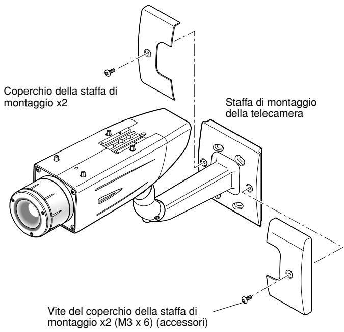
natural_image
Illustration of a woman with long hair and moon, framed by decorative borders (no text or symbols)Notturno
natural_image
Simple line drawing of a woman with long hair and a bow, framed by decorative curtains (no text or symbols)Diurno
SUPER-D3 OFF
natural_image
Illustration of a woman with long hair and a crescent moon, framed by patterned fabric (no text or symbols)Notturno
natural_image
Illustration of a person with long hair and a patterned top, framed by decorative curtains (no text or symbols)Diurno
natural_image
Line drawing of a woman with long hair and a patterned garment, viewed from behind a grid background (no text or symbols)Nota:
natural_image
Empty rounded rectangle with a small plus sign in the center (no text or symbols beyond the plus)natural_image
Symbolic illustration of a person climbing a ladder inside a circle with a diagonal line (no text or symbols)natural_image
Technical line drawing of a surveillance camera connected to an open electrical enclosure (no text or symbols present)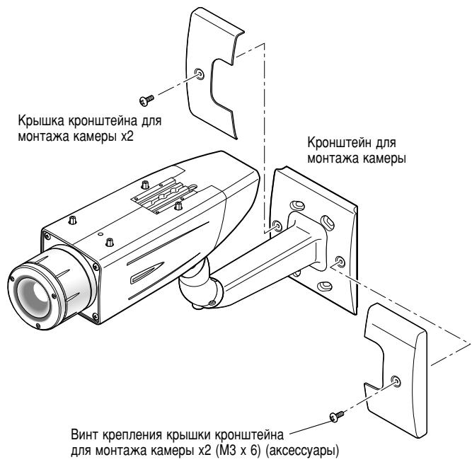
natural_image
Pure mechanical component diagram with no text, numbers, or symbolsnatural_image
Technical line drawing of a square electronic device with internal components and mounting holes (no text or symbols)Крепежный винт x4
Примечание:
natural_image
Pure diagram of a circular component with four corner connectors and internal diagonal hatching, no text or symbols present.Крепежный винт x4
natural_image
Illustration of a woman with long hair and a crescent moon, framed by decorative panels (no text or symbols)Ночное время
natural_image
Simple line drawing of a woman with long hair and a patterned curtain background (no text or symbols)Дневное время
SUPER-D3 ВЫКЛ

natural_image
Illustration of a girl with long hair and crescent moon, framed by a patterned curtain background (no text or symbols)Ночное время

natural_image
Illustration of a person with long hair and a bow, framed by decorative curtains (no text or symbols)Дневное время
natural_image
Line drawing of a woman with long hair and a patterned garment, viewed from behind a grid background (no text or symbols)Примечание:
natural_image
Empty rounded rectangle with a small plus sign in the center (no text or symbols beyond the plus)Importer's name and address to follow EU rules:
Panasonic Testing Centre
Panasonic Marketing Europe GmbH
Winsbergring 15, 22525 Hamburg F.R.Germany
© Panasonic System Networks Co., Ltd. 2010
Ns0508-3010 3TR005538EZA
Printed in China
Gedruckt in China
Imprimé en Chine
Impreso en China
Напечатано в Китае