
CFB5310W - Refrigerator-freezer BEKO - Free user manual and instructions
Find the device manual for free CFB5310W BEKO in PDF.


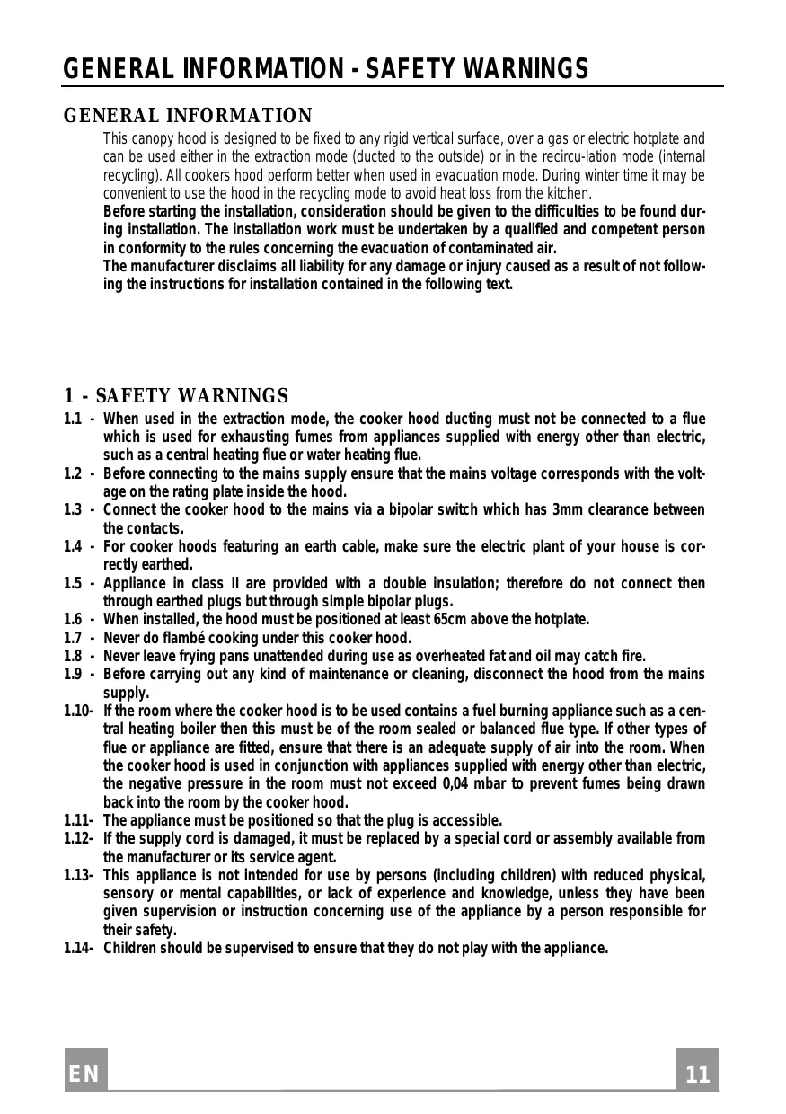


| Product type | Combined refrigerator-freezer |
| Brand | BEKO |
| Model | CFB5310W |
| Energy class | A+ |
| Total net volume | 310 L (refrigerator 210 L, freezer 100 L) |
| Dimensions (H x W x D) | 185 x 60 x 65 cm |
| Net weight | 68 kg |
| Electrical supply | 220-240 V, 50 Hz, 1.2 A |
| Cooling technology | Static fan (forced air cooling) |
| Defrosting | Automatic (No Frost) in freezer compartment |
| Sensors and display | Mechanical thermostat, interior LED lighting |
| Reversible door | Yes, can be reversed |
| Number of shelves | 4 glass shelves, 1 vegetable drawer, 1 freezer shelf |
| Climate class | N-ST (ambient temperature from 16 °C to 38 °C) |
| Noise level | 41 dB(A) |
| Annual consumption | Approximately 240 kWh |
| Maintenance and cleaning | Clean the interior with a soft cloth and soapy water. Defrost the refrigerator manually if necessary. Door seals should be cleaned regularly. |
| Safety | Child lock, open door alarm, overheating safety |
| Spare parts and repairability | Parts availability from BEKO after-sales service. Repairability index: 7.8/10 |
| General information | Freestanding appliance, white color, 2-year warranty |
Frequently Asked Questions - CFB5310W BEKO
User questions about CFB5310W BEKO
0 question about this device. Answer the ones you know or ask your own.
Ask a new question about this device
Download the instructions for your Refrigerator-freezer in PDF format for free! Find your manual CFB5310W - BEKO and take your electronic device back in hand. On this page are published all the documents necessary for the use of your device. CFB5310W by BEKO.
USER MANUAL CFB5310W BEKO
Instructions Manual INDEX
GENERAL INFORMATION - SAFETY WARNINGS 11
INSTALLATION 12
USE - MAINTENANCE 13
Instructions Manual TABLE OF CONTENTS
GENERAL INFORMATION - SAFETY WARNINGS 14
INSTALLATION 15
USE - MAINTENANCE 16
OPERATION AND TECHNICAL MAINTENANCE 25
User Manual CONTENTS
GENERAL INFORMATION - SAFETY WARNINGS 26
INSTALLATION 27
USE - MAINTENANCE AND CLEANING 28
Instruction Manual CONTENTS
GENERAL INFORMATION - SAFETY WARNINGS 29
MONTAVIMAS 30
NAUDOJIMAS - VALYMAS IR PRIEŽIŪRA 31
Evyεipidio oδηiων έπΕΠΕXΟΜΕΝΑ
TENIKA - IPOEIOIOIHSEIIGIA THN AΦAIEIA 32
EΓΚATAΣTAΣH. 33
XPHSH-SYNTHPHSH 34
This canopy hood is designed to be fixed to any rigid vertical surface, over a gas or electric hotplate and can be used either in the extraction mode (ducted to the outside) or in the recirculation mode (internal recycling). All cooker hoods perform better when used in evacuation mode. During winter time it may be convenient to use the hood in the recycling mode to avoid heat loss from the kitchen.
Before starting the installation, consideration should be given to the difficulties to be found during installation. The installation work must be undertaken by a qualified and competent person in conformity to the rules concerning the evacuation of contaminated air.
The manufacturer disclaims all liability for any damage or injury caused as a result of not following the instructions for installation contained in the following text.
1 - SAFETY WARNINGS
1.1 - When used in the extraction mode, the cooker hood ducting must not be connected to a flue which is used for exhausting fumes from appliances supplied with energy other than electric, such as a central heating flue or water heating flue. 1.2 - Before connecting to the mains supply ensure that the mains voltage corresponds with the voltage on the rating plate inside the hood. 1.3 - Connect the cooker hood to the mains via a bipolar switch which has 3mm clearance between the contacts. 1.4 - For cooker hoods featuring an earth cable, make sure the electric plant of your house is correctly earthed. 1.5 - Appliance in class II are provided with a double insulation; therefore do not connect then through earthed plugs but through simple bipolar plugs. 1.6 - When installed, the hood must be positioned at least 65cm above the hotplate. 1.7 - Never do flambe cooking under this cooker hood. 1.8 - Never leave frying pans unattended during use as overheated fat and oil may catch fire. 1.9 - Before carrying out any kind of maintenance or cleaning, disconnect the hood from the mains supply. 1.10- If the room where the cooker hood is to be used contains a fuel burning appliance such as a central heating boiler then this must be of the room sealed or balanced flue type. If other types of flue or appliance are fitted, ensure that there is an adequate supply of air into the room. When the cooker hood is used in conjunction with appliances supplied with energy other than electric, the negative pressure in the room must not exceed 0,04 mbar to prevent fumes being drawn back into the room by the cooker hood. 1.11- The appliance must be positioned so that the plug is accessible. 1.12- If the supply cord is damaged, it must be replaced by a special cord or assembly available from the manufacturer or its service agent. 1.13- This appliance is not intended for use by persons (including children) with reduced physical, sensory or mental capabilities, or lack of experience and knowledge, unless they have been given supervision or instruction concerning use of the appliance by a person responsible for their safety. 1.14- Children should be supervised to ensure that they do not play with the appliance.
2 - INSTALLATION INSTRUCTIONS
Some installation systems require the opening and removal of the metal grille panel.
2.1 - Instructions for opening and removing the metal grille panel
To open the grille panel, press inwardly on the two slider catches at each side of the grille panel and the grille will pivot down.
To remove the metal grille, pull forward on the right hand side so that the hinge pin on the back of the grille will be released from the slot in the side of the casing.
2.2 - Wall cabinet fixing
a - Predrilled wall cabinet: fix the hood onto the wall cabinet base panel using the four screws 4.2 × 45 mm (supplied with the fixing kit).
It is not necessary to open the metal grille. b - No predrilled wall cabinet:
b.1 - If the hood is provided with a paper fixing template, follow the instructions. b.2 - If the hood is not provided with a paper fixing template, position the hood on the wall cabinet base panel and pilot drill the 3.5 × 16 mm screws (not supplied with the fixing kit) from the inside onto the wood.
2.3 - Wall mounting
a - Drill two 0.8 mm holes on the wall using the paper template, insert two rawl plugs and two 4.2 × 44.4 mm screws leaving 5 mm untightened. Open the metal grille panel, hook the hood on and fully tighten the screws. b - If the hood is not provided with a paper fixing template, drill two 0.8 mm holes (see drawing), insert the plugs and screws, proceeding as directed under paragraph a. c - For wall mounting using wall brackets (optional), follow the instructions of the fixing template. d - Pay attention to the safety regulation of point 1.6.
2.4 - Choice of operating mode
a - Evacuation mode: To check that the hood is set up for evacuation, open the grille panel and make sure that the conversion lever or the change-over knob on the centrifugal unit is in the DUCTING position. The charcoal filter is not required. For ducting to the outside, the hood is supplied with a rear and top outlet. A flange spigot of 100 mm diameter (120 mm in certain models) is usually fitted on the top outlet and a blanking plug on the rear outlet. If you choose to duct the hood from the rear of the casing, you should invert the position of the flange and of the blanking plug. Pay attention to the safety regulation 1.1. b - Internal recirculation mode
To check that the hood is set up for recycling, open the grille panel and make sure that the conversion lever or the change-over knob on the centrifugal unit is in the RECYCLING position.
The charcoal filter is to be fitted. To fit the charcoal filter, support the filter with one hand and turn the thumb screw through the centre of the charcoal filter. If the filter is of the interlocking type, turn the filter clockwise. The hood can remain connected to the outside.
2.5 - Electrical connection and working test
1 - The safety measures 1.2, 1.3, 1.4 and 1.5 of paragraph 1 are to be strictly observed. 2 - Once the electrical connection has been completed, check that the worktop illumination, motor and speeds work properly.
3 - OPERATION
3.1 - Controls are located on the right hand side of the front to operate worktop illumination and select the most suitable working speed for your cooking. To increase the area of extraction, the glass visor should be pulled open. The top speed should be used when frying or cooking foods with strong odours, while a lower speed can be used for normal cooking. To obtain the best performance from your hood, turn it on before you start cooking and leave it running for a few minutes after your cooking is over to clear the air. 3.2 - Pay attention to safety regulations 1.7 and 1.8.
4 - MAINTENANCE AND CLEANING
Regular maintenance and cleaning will ensure good performance and reliability, while extending the working life of the hood. Special attention should be reserved for the grease filter and the charcoal filter (recycling mode).
4.1 - Grease filter
This retains the solid grease particles and can be supplied in different types. It is fitted onto the reverse side of the metal grille panel. Maintenance of the grease filter varies according to the type used. a- Whatever type of filter is used, the filter is easily removed from the grille by pushing the metal wire clips to one side and removing. b- Thin synthetic filter (1 mm thick). It should not be washed and should be replaced every two months. If the filter is provided with a saturation indicator, replace when:
b.1- The violet colour of the dots, which are visible through the metal grille, is spread over the whole surface of the filter. b.2- The red colour of the stripes, which is not visible through the metal grille when the filter is clean, becomes visible from the outside of the metal grille.
c- Multi-layer metal filter. It should be washed once a month in hot water using mild detergent or liquid soap. It can be washed in a dishwasher. It should not be bent and should be left to drain dry.
WARNING: An excess of grease in the filter not only would affect the performance of the hood, but it is also a possible fire risk. We strongly recommend therefore to clean and replace filters in accordance with the manufacturer's instructions.
4.2 - Cleaning Metal Self-supporting Grease Filters
- The filters are washable and must be cleaned at least every 2 months of operation, or more frequently for particularly heavy usage.
- Remove the filters one at a time by pushing them towards the back of the group and pulling down at the same time.
- Wash the filters, taking care not to bend them. Allow them to dry before refitting.
- When refitting the filters, make sure that the handle is visible on the outside.
4.3 - Charcoal filter
The charcoal filter is a chemical filter to be used only when the hood is in the recycling position. To replace the charcoal filter, open the grille and remove the thumb screw through the centre of the charcoal filter. If the filter is of the interlocking type, turn the filter anticlockwise. Replace by reversing the operation. For good performance, replace the charcoal filter on average every three months.
4.4 - Worktop illumination
If a lamp fails to function at any time, open the metal grille panel and check that the lamp is fully screwed into the holder. When changing the lamp, an identical replacement must be fitted to ensure safe working of the hood.
4.5 - Cleaning
The metal work should be cleaned regularly, at least once a month, using mild household cleaner and polish. Never use abrasives. For all operations from point 4.1 to point 4.4 and in particular for point 4.3, pay special attention to the safety regulation 1.9.
GENERAL - SAFETY ADVICE
GENERAL
Some installation systems provide for opening and closing the suction grille.
2.1 - Opening and closing the suction grille
To open the grille, press the center of the lower part of the extractor. Rotating on two rear pins, the grille will lower.
When the grille is open and in the vertical position, push the right rear pin forward along the side slot, so that the grille is held in position.
2.2 - Installation of the shelf
a- Shelf with holes: connect the extractor to the shelf using the holes made in the base of the shelf with the 4 screws 4.2 x 44.4 supplied. Opening the grille is not necessary. b- Shelf without holes:
b.1- If a duct for extraction is supplied with the extractor, follow the instructions given on it. b.2- If there is no duct, open the grille, place the extractor against the base of the shelf and screw it from inside the shelf with screws 3.5 x 16 (not supplied).
2.3 - Wall mounting of the shelf
a- Using the duct as a template, drill the holes, insert the wall plugs and screws 4.2 x 44.0, leaving 5 mm protruding. Remove the suction grille, hang the extractor on the screws and tighten them fully from the inside of the shelf. b- If there is no duct, make 2 holes of 8 mm (see figure) and insert the plugs and screws, following point a. c- For wall mounting using the bracket (optional), follow the instructions given on the special supplied duct. d- Observe the rule given in point 1.6.
2.4 - Choice of model
a- Suction
Open the suction inlet and set the handle for the pointer knob to the "Suction" position at the end of its travel. If the cartridge is at the activated angle, turn the central handle to slowly rotate the cartridge counterclockwise to disengage the central bayonet connection. Connect the external hose (100 mm, or 120 mm in some models) located at the top or rear exhaust outlet, as needed. Insert a plug into the remaining free opening. Strictly follow the rules in section 1.1.
Open the suction inlet and set the handle for the pointer knob to the "Filtering" position at the end of its travel. Place the cartridge on the activated angle on the motor support using the central metal handle to slowly rotate the cartridge clockwise to engage the central side connection. The external hose, if present, may be connected.
2.5 - Electrical connection and functional test
1- It is necessary to strictly observe the safety instructions in sections 1.2, 1.3, 1.4, and 1.5 of section 1. 2- After completing the electrical connection, check the operation of the lighting, the motor switch, and the speed control.
3- OPERATION
3.1 - The switches control the extraction on/off, the speed control of the motor, and the lighting of the plate. For optimal operation of the appliance, it is recommended to open the hood and set the motor to high speed in case of high concentration of odors and cooking fumes, and for quiet and economical air exchange, adjust the speed to medium or low. It is advisable to turn on the extraction at the beginning of the cooking process and leave it on for a few minutes after the end of cooking. 3.2 - Strictly observe the warnings in sections 1.7 and 1.8.
4- MAINTENANCE AND CLEANING
Good maintenance ensures high quality of work and long service life of the appliance.
WARNING: Accumulation of grease inside the filter not only reduces the efficiency of the appliance, but may also create a fire hazard. Therefore, it is recommended to carefully follow the instructions given below.
The symbol on the product or on its packaging indicates that this product may not be treated as household waste. Instead it shall be handed over to the applicable collection point for the recycling of electrical and electronic equipment. By ensuring this product is disposed of correctly, you will help prevent potential negative consequences for the environment and human health, which could otherwise be caused by inappropriate waste handling of this product. For more detailed information about recycling of this product, please contact your local city office, your household waste disposal service or the shop where you purchased the product.


- INSTRUCTIONS MANUAL INDEX
- INSTRUCTIONS MANUAL TABLE OF CONTENTS
- USER MANUAL CONTENTS
- INSTRUCTION MANUAL CONTENTS
- EVYΕIPIDIO OΔΗIΩΝ ΈΠΕΠΕXΟΜΕΝΑ
- SAFETY WARNINGS
- INSTALLATION INSTRUCTIONS
- INSTRUCTIONS FOR OPENING AND REMOVING THE METAL GRILLE PANEL
- WALL CABINET FIXING
- WALL MOUNTING
- CHOICE OF OPERATING MODE
- ELECTRICAL CONNECTION AND WORKING TEST
- OPERATION
- MAINTENANCE AND CLEANING
- GREASE FILTER
- CLEANING METAL SELF-SUPPORTING GREASE FILTERS
- CHARCOAL FILTER
- WORKTOP ILLUMINATION
- CLEANING
- GENERAL - SAFETY ADVICE
- GENERAL
- OPENING AND CLOSING THE SUCTION GRILLE
- INSTALLATION OF THE SHELF
- WALL MOUNTING OF THE SHELF
- CHOICE OF MODEL
- ELECTRICAL CONNECTION AND FUNCTIONAL TEST
Brand : BEKO
Model : CFB5310W
Category : Refrigerator-freezer