
CC SERIES - Power Amplifiers CREST AUDIO - Free user manual and instructions
Find the device manual for free CC SERIES CREST AUDIO in PDF.
| Product type | Professional power amplifier |
| Brand | CREST AUDIO |
| Model | CC Series (CC1800, CC2800, CC4000) |
| Dimensions (H x W x D) | 88.9 mm x 482.6 mm x 377.8 mm (+ 31.8 mm rear supports) |
| Net weight | From 14.8 kg (CC1800) to 19.6 kg (CC4000) |
| Power supply | 120 VAC / 60 Hz (North America), 230 VAC / 50 Hz (Europe, Asia), 240 VAC / 50 Hz (Australia) |
| Power consumption (1/8 power, 4 ohms) | Approximately 880 W (CC2800) |
| Output power (2 channels, 4 ohms) | From 700 W (CC1800) to 1350 W (CC4000) per channel |
| Output power (bridge, 4 ohms) | From 1850 W (CC1800) to 4000 W (CC4000) |
| Minimum load impedance | 2 ohms (stereo/parallel), 4 ohms (bridge) |
| Frequency response | 10 Hz - 100 kHz (+0, -2 dB @ 1 watt) |
| Selectable gain | x40 (32 dB) or x20 (26 dB) |
| Input sensitivity (x40, 4 ohms) | 1.7 V (CC2800) |
| Damping factor | > 500:1 (20 Hz - 1 kHz, 8 ohms) for CC2800/CC4000 |
| Signal-to-noise ratio | > 111 dB (A-weighted) for CC2800 |
| Input connectors | Combo XLR / 6.35 mm jack (balanced) |
| Output connectors | Speakon® and 5-way binding post |
| Cooling | 1 or 2 80 mm variable speed fans depending on temperature |
| Built-in protections | Thermal, DC, short circuit, subsonic, ACL, IGM, AUTORAMP |
| LED indicators (per channel) | ACL, Signal, Temp, Active |
| Construction | 16 ga. steel chassis, cast front panel, 19" rack mount |
| Maintenance and cleaning | Regular dusting, cleaning with a dry cloth, do not block ventilation |
| Safety | Do not open, do not expose to moisture, disconnect before maintenance, use a grounded outlet |
| After-sales service | Contact an authorized Crest Audio center or the dealer |
Frequently Asked Questions - CC SERIES CREST AUDIO
User questions about CC SERIES CREST AUDIO
0 question about this device. Answer the ones you know or ask your own.
Ask a new question about this device
Download the instructions for your Power Amplifiers in PDF format for free! Find your manual CC SERIES - CREST AUDIO and take your electronic device back in hand. On this page are published all the documents necessary for the use of your device. CC SERIES by CREST AUDIO.
USER MANUAL CC SERIES CREST AUDIO
CC™ Power Amplifier Owner's Manual


Intended to alert the user to the presence of uninsulated "dangerous voltage" within the product's enclosure that may be of sufficient magnitude to constitute a risk of electric shock to persons.

Intended to alert the user of the presence of important operating and maintenance (servicing) instructions in the literature accompanying the product.
CAUTION: Risk of electrical shock — DO NOT OPEN!
CAUTION: To reduce the risk of electric shock, do not remove cover. No user serviceable parts inside. Refer servicing to qualified service personnel.
WARNING: To prevent electrical shock or fire hazard, do not expose this appliance to rain or moisture. Before using this appliance, read the operating guide for further warnings.

WARNING: When using electrical products, basic cautions should always be followed, including the following:
- Read these instructions.
- Keep these instructions.
- Heed all warnings.
- Follow all instructions.
- Do not use this apparatus near water.
- Clean only with a dry cloth.
- Do not block any of the ventilation openings. Install in accordance with manufacturer's instructions.
- Do not install near any heat sources such as radiators, heat registers, stoves or other apparatus (including amplifiers) that produce heat.
- Do not defeat the safety purpose of the polarized or grounding-type plug. A polarized plug has two blades with one wider than the other. A grounding type plug has two blades and a third grounding plug. The wide blade or third prong is provided for your safety. If the provided plug does not fit into your outlet, consult an electrician for replacement of the obsolete outlet.
- Protect the power cord from being walked on or pinched, particularly at plugs, convenience receptacles, and the point they exit from the apparatus.
- Only use attachments/accessories provided by the manufacturer.
- Use only with a cart, stand, tripod, bracket, or table specified by the manufacturer, or sold with the apparatus. When a cart is used, use caution when moving the cart/apparatus combination to avoid injury from tip-over.
Unplug this apparatus during lightning storms or when unused for long periods of time. - Refer all servicing to qualified service personnel. Servicing is required when the apparatus has been damaged in any way, such as power-supply cord or plug is damaged, liquid has been spilled or objects have fallen into the apparatus, the apparatus has been exposed to rain or moisture, does not operate normally, or has been dropped.
- Never break off the ground pin. Write for our free booklet "Shock Hazard and Grounding." Connect only to a power supply of the type marked on the unit adjacent to the power supply cord.
- If this product is to be mounted in an equipment rack, rear support should be provided.
- Note for UK only: If the colors of the wires in the mains lead of this unit do not correspond with the terminals in your plug, proceed as follows:
C
a) The wire that is colored green and yellow must be connected to the terminal that is marked by the letter E, the earth symbol, colored green or colored green and yellow.
b) The wire that is colored blue must be connected to the terminal that is marked with the letter N or the color black.
c) The wire that is colored brown must be connected to the terminal that is marked with the letter L or the color red.
- This electrical apparatus should not be exposed to dripping or splashing and care should be taken not to place objects containing liquids, such as vases, upon the apparatus.
- Exposure to extremely high noise levels may cause a permanent hearing loss. Individuals vary considerably in susceptibility to noise-induced hearing loss, but nearly everyone will lose some hearing if exposed to sufficiently intense noise for a sufficient time. The U.S. Government's Occupational Safety and Health Administration (OSHA) has specified the following permissible noise level exposures:
| Duration Per Day In Hours | Sound Level dBA, Slow Response |
| 8 | 90 |
| 6 | 92 |
| 4 | 95 |
| 3 | 97 |
| 2 | 100 |
| 1 1/2 | 102 |
| 1 | 105 |
| 1/2 | 110 |
| 1/4 or less | 115 |
According to OSHA, any exposure in excess of the above permissible limits could result in some hearing loss. Ear plugs or protectors to the ear canals or over the ears must be worn when operating this amplification system in order to prevent a permanent hearing loss, if exposure is in excess of the limits as set forth above. To ensure against potentially dangerous exposure to high sound pressure levels, it is recommended that all persons exposed to equipment capable of producing high sound pressure levels such as this amplification system be protected by hearing protectors while this unit is in operation.
Save the carton and packing materials! Should you ever need to ship the unit, use only the original factory packing.
For replacement packaging, call Crest Audio's Customer Service Department directly.
Read all documentation before operating your equipment. Retain all documentation for future reference.
3 Follow all instructions printed on unit chassis for proper operation.
4 Never hold a power switch or circuit breaker in the "on" position, if it won't stay there by itself!
5 Do not use the unit if the electrical power cord is frayed or broken.
The power supply cords should be routed so that they are not likely to be walked on or pinched by items placed upon or against them.
Always operate the unit with the AC ground wire connected to the electrical system ground. Precautions should be taken so that the means of grounding of a piece of equipment is not defeated.
7 Damage caused by connection to improper AC voltage is not covered by any warranty. Mains voltage must be correct and the same as that printed on the rear of the unit.
8 Do not ground any hot (red) terminal.
Never connect a hot (red) output to ground or to another hot (red) output!
9 Power down and disconnect units from mains voltage before making connections.
10 Do not drive the inputs with a signal level greater than that required to enable equipment to reach full output.
11 Do not run the output of any amplifier channel back into another channel's input.
Do not parallel- or series-connect an amplifier output with any other amplifier output.
Crest Audio is not responsible for damage to loudspeakers for any reason.
12 Do not connect the inputs or outputs of amplifiers to any other voltage source: such as a battery, mains source, or power supply, regardless of whether the amplifier is turned on or off.
13 Connecting amplifier outputs to oscillosopes or other test equipment while the amplifier is in bridged mono mode may damage both the amplifier and test equipment!
14 Do not spill water or other liquids into or on the unit, or operate the unit while standing in liquid.
15 Do not block fan intake or exhaust ports.
Do not operate equipment on a surface or in an environment which may impede the normal flow of air around the unit: such as a bed, rug, weathersheet, carpet, or completely enclosed rack.
16 If the unit is used in an extremely dusty or smoky environment: the unit should be periodically blown free of foreign matter.
17 Do not use the unit near stoves, heat registers, radiators, or other heat producing devices.
18 The power cord of equipment should be unplugged from the outlet when left unused for a long period of time.
Service Information
Do not remove the cover!
Removing the cover will expose you to potentially dangerous voltages. There are no user serviceable parts inside.
Equipment should be serviced by qualified service personnel when:
A. The power supply cord or the plug has been damaged.
B. The equipment has been exposed to rain.
C. The equipment does not appear to operate normally, or exhibits a marked change in performance.
D. The equipment has been dropped, or the enclosure damaged.
To obtain service:
contact your nearest Crest Audio Service Center, Distributor, Dealer, or Crest Audio at 201.909.8700 USA or visit www.crestaudio.com for additional information.
email techserve@crestaudio.com
This symbol is used to alert the operator to follow important procedures and precautions detailed in documentation.

This symbol is used to warn operators that uninsulated "dangerous voltages" are present within the equipment enclosure that may pose a risk of electric shock.
WARNING
THE ON/OFF SWITCH IN THIS APPARATUS DOES NOT BREAK BOTH SIDES OF THE MAINS. HAZARDOUS ENERGY MAY BE PRESENT INSIDE THE ENCLOSURE WHEN THE POWER SWITCH IS IN THE OFF POSITION.
1 how to use this manual p.2 introduction p.3
2 installation p.4 unpacking mounting connecting power cooling requirements operating precautions connecting inputs connecting outputs
3 features overview p.6 front panel rear panel
4 operation modes p.9 stereo parallel bridged mono
5 protection features p.10 automatic clip limiting IGMTM impedance sensing thermal protection short circuit DC voltage protection turn on/off protection AUTORAMP* signal control
6 safety p.12 speaker protection user responsibility
7 service and support p.13 support contact us
a specifications p.14
b wire gauge charts p.17
contents
appendices
ENGLISH p.1
DEUTSCH p.19
FRANÇAIS p.39
ESPANOL p.58
conventions
terms
official Crest Audio features and each indicator or control on the amplifier will appear as: terms
actions
specific actions or selections the user can execute will appear as: actions
tasks
are broken down into steps 1
2
3
\section*{ warnings}
Procedures not to attempt.

Issues or hazards to keep in mind when operating the equipment.
indicators
What to look for on the equipment display.

Alerts, indicators, or prompts that may appear.
tips
Preferred methods.
Helpful hints.
Feature insights.

see
see—refers to other sections of the manual containing supplementary information on the current topic or a related issue
note
note—supplementary feature information
welcome
Congratulations on your purchase of a Crest Audio CC™ Series power amplifier. Designed for years of reliable, flawless operation under rigorous use. The Crest CC Series amplifiers offer the sonic superiority and unsurpassed reliability for which Crest Audio is famous, while remaining surprisingly compact. Advanced technology and extensive protection circuitry allow operation with greater efficiency into difficult loads and power conditions. The ACL™ (Automatic Clip Limiting) circuit ensures trouble-free operation into loads as low as 2 ohms. The Automatic Clip Limiting circuits protect drivers and ensure that sonic integrity is maintained, even in extreme overload conditions. Crest Audio's high-efficiency designs use tunnel-cooled heat sinks and variable speed DC fans. This cooling topology maintains a lower overall operating temperature, resulting in longer output transistor life. Model CC 4000, CC 2800, and CC 1800 power amplifiers use Crest Audio's innovative "Power Density" circuitry and packaging.
For your safety,
read the important precautions section, as well as input, output, and power connection sections.
unpacking
Upon unpacking, inspect the amplifier. If you find any damage, notify your supplier immediately. Only the consignee may institute a claim with the carrier for damage incurred during shipping. Be sure to save the carton and all packing materials. Should you ever need to ship the unit back to Crest Audio, one of its offices, service centers, or the supplier, use only the original factory packing. If the shipping carton is unavailable, contact Crest to obtain a replacement.
mounting
CC Series amplifiers will mount in standard 19" racks. Rear mounting ears are also provided for additional support, which is recommended in non-permanent installations like mobile or touring sound systems. Because of the cables and connectors on the rear panel, a right angle or offset screwdriver or hex key will make it easier to fasten the rear mounting ears to the rails.
connecting power
CC Series amplifier power requirements are rated at 1/8^th power (typical music conditions) and 1/3^rd power (extreme music conditions). The maximum power current draw rating is limited only by the front panel circuit breaker. Consult the specifications in the Appendices section for figures on the current that each amplifier will demand. Make sure the mains voltage is correct and is the same as that printed on the rear of the amplifier. Damage caused by connecting the amplifier to improper AC voltage is not covered by any warranty. Unless otherwise specified when ordered, Crest amplifiers shipped to customers are configured as follows:
Option | North America | 120VAC / 60 Hz
Option 2 Europe, Asia 230VAC / 50 Hz
Option 3 Australia 240VAC / 50 Hz
Option 4 South America 120VAC / 60 Hz or 240VAC / 50 Hz
For replacement
packaging, call Crest
Audio's
Customer Service
Department directly.
see—service and support

Always turn off and
disconnect the amplifier
from mains voltage before
making audio connections.
Also, as an extra precaution,
have the attenuators turned
down during power-up.
cooling requirements
The CC™ Series amplifiers use a forced-air cooling system to maintain a low, even operating temperature. Air is drawn into the amplifier by fan(s) on the rear panel, courses through the cooling fins of the tunnel-configured channel heat sink(s), and then exhausts through the front panel grille. If a heat sink gets too hot, its sensing circuit will open the output relay, disconnecting the load from that particular channel. The CC 1800 utilizes one common heat sink and a single fan, but retains the separate circuitry. It is important to have an adequate air supply at the back of the amplifier and enough space around the front of the amplifier to allow the cooling air to escape. If the amp is rack mounted, do not use doors or covers on the front of the rack; the exhaust air must flow without resistance. If you are using racks with closed backs, use fans on the rear rack panel to pressurize the rack and ensure an ample air supply.
operating precautions
Make sure the mains voltage is correct and is the same as that printed on the rear of the amplifier. Damage caused by connecting the amplifier to improper AC voltage is not covered by any warranty. See the Connecting Power section for more information on voltage requirements.
Although the CC Series amplifiers have AUTORAMP™ circuitry, which raises the signal level gradually after the output relay closes, it is always a good idea to have the gain controls turned down during power-up to prevent speaker damage if there is a high signal level at the inputs. Whether you buy or make them, use good-quality connections, input cables and speaker cables, along with good soldering technique, to ensure trouble-free operation. Most intermittent problems are caused by faulty cables.
Consult the Wire Gauge Charts to determine proper gauges for different load impedances and cable lengths. Remember that cable resistance robs amplifier power in two ways: power lost directly to resistance (I²R loss), and by increasing the impedance of the load presented to the amplifier, thereby decreasing the power demanded of the amplifier. Also make sure the mode switch is correctly set for the desired application. See Sections on Stereo, Parallel and Bridged Mono Operation for more information.
connecting inputs
Input connections are made via the 3-pin XLR (pin 2+ ) or 6.3 mm plug "Combi" connectors on the rear panel of the amplifier. The inputs are actively balanced. The input overload point is high enough to accept the maximum output level of virtually any signal source.
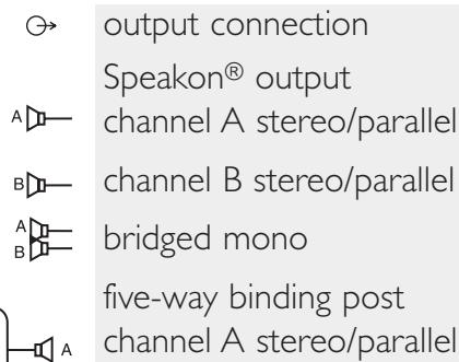
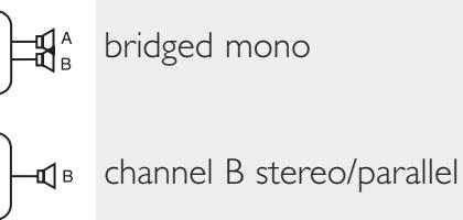
connecting outputs
All models have two output (speaker) connections per channel. Cables can be connected with banana plugs, spade lugs, or bare wire to the five-way binding posts. The preferred method is connection via the Speakon connectors.
Make certain that there is enough space around the front and rear of the amplifier to allow the heated air to escape.
suggestion: In racks with closed backs allow at least one standard-rack-space opening for every four amps.


Always turn off and disconnect the amplifier from mains voltage before making audio connections. Also, as an extra precaution, turn the attenuators down during power-up.
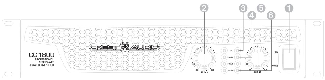
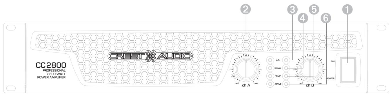
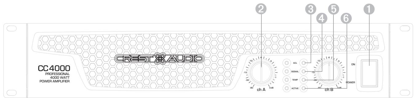
front panel
switches and controls
1 AC Power Switch/Circuit Breaker
The CC Series amplifiers have a combination AC switch/circuit breaker on the front panel. If the switch shuts off during normal use, push it back to the ON position once. If it will not stay on, the amplifier needs servicing.
Input Attenuators
Whenever possible, set the attenuators fully clockwise to maintain optimum system headroom. The input attenuator controls (one for channel A, one for channel B) located at the front panel adjust gain for their respective amplifier channels in all modes. See the specifications at the end of this manual for standard voltage gain and input sensitivity information.
indicators
CC Series amplifiers feature four front panel LED indicators per channel: ACL^TM (Automatic Clip Limiting), Signal, Temp, and Active. These LED indicators inform the user of each channel's operating status and warn of possible abnormal conditions.
3 ACL LED
A channel's ACL LED will light at the onset of clipping. If the LED's are flashing quickly and intermittently, the channel is just at the clip threshold, while a steady, bright glow means the amp is clip limiting, or reducing gain to prevent severely clipped waveforms reaching the loudspeakers. See the Automatic Clip Limiting section for more information. During initial power up the ACL LED will light indicating that the AUTORAMP™ gain reduction circuitry is activated. This will prevent sudden signal bursts when the speaker relays are closed.
④ Signal LED
This LED lights when its channel produces an output signal of about 4 volts RMS or more (0.1 volt or more at the input, with 0 dB attenuation and standard x40 voltage gain). It is useful in determining whether a signal is reaching and being amplified by the amplifier.
⑤ Temp LED
The Temp LED lights to indicate that the channel's output relay is open, disconnecting the speaker(s) due to an overheating condition. Once the channel temperature has returned to safe operating conditions the LED will turn off, the channel's output relay will close, and the speaker(s) will be reconnected.
Active LED
The Active LED indicates that its channel's output relay is closed and the channel is operational. It lights under normal operation and remains on even when the channel is in Automatic Clip Limiting or ACL gain reduction. These are protection features which leave the output relay closed. If the Active LED goes off, there is no signal at the output connectors.
The power only breaks one side of the AC mains. Hazardous energy may be present in the enclosure when the power switch is in the off position.


When operating in the bridged mode, both attenuators must be in the same position so the speaker load will be equally shared between the channels. See the section on Bridged Mono Operation for more information and precautions.

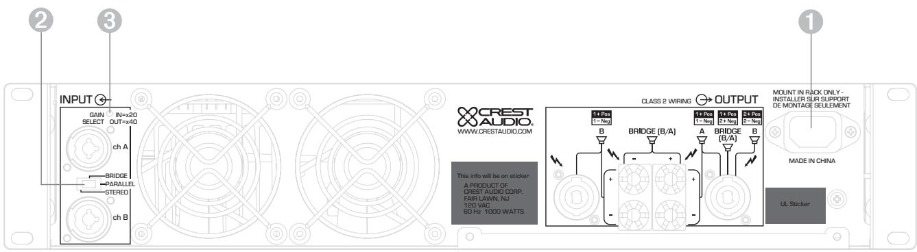
rear panel
IEC power connector
Accepts a standard IEC terminated power cable
Mode Select Switch
The rear panel Mode Select Switch determines whether the amplifier is in the stereo, parallel, or bridged mono mode. Do not operate the Mode Select Switch with the amplifier powered on. See the sections on Stereo and Bridged Mono Mode for more information.
Gain Select Switch
The rear panel Gain Select Switch determines whether the amplifier has an overall gain of 40 (32 dB) or a gain of 20 (26 dB). The out position will select x40 while the in position will select x20.
rear panel legend
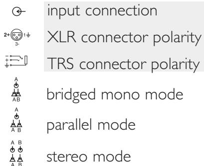
stereo
For stereo (dual channel) operation, turn the amplifier off and set the mode select switch to the stereo position. In this mode, both channels operate independently of each other, with their input attenuators controlling their respective levels. Thus, a signal at channel A's input produces an amplified signal at channel A's output, while a signal at channel B's input produces an amplified signal at channel B's output.
parallel
For parallel (dual-channel/single input) operation, turn the amplifier off and set the mode switch in the parallel position; both amplifier channels are then driven by the signal at channel A's input. No jumper wires are needed. Output connections are the same as in the stereo mode. Channel A's and channel B's input connectors are strapped together to allow patching to another amplifier. Both input attenuators remain active, allowing you to set different levels for each channel. Power and other general performance specifications are the same as in the stereo mode.
bridged mono
Both amplifier channels can be bridged together to make a very powerful single-channel monaural amplifier. Use extreme caution when operating in the bridged mode; potentially lethal voltage may be present at the output terminals. To bridge the amplifier, turn the amplifier off and slide the rear panel amplifier mode select switch to the bridge position. Apply the signal to channel A's input and connect the speakers across the hot outputs which are either the "+" binding posts of channels A and B. Alternately connect across pins "I+POS" and "2+NEG" of the channel A Speakon® connector. As with parallel operation, both input connectors are strapped together to drive the input of another amplifier.
Unlike the stereo and parallel modes, in which one side of each output is at ground, in the bridged mode both sides are hot. Channel A's side is the same polarity as the input. The minimum nominal load impedance in the bridged mode is 4 ohms which is equivalent to driving both channels at 2 ohms. Driving bridged loads of less than 4 ohms will activate the ACL circuitry resulting in a loss of power, and may also cause a thermal overload.
When operating in the bridged mode, both attenuators must be in the same position so the speaker load will be equally shared between the channels.

CC Series amplifiers incorporate several circuits to protect both themselves and loudspeakers under virtually any situation. Crest Audio has attempted to make the amplifiers as foolproof as possible by making them immune to short and open circuits, mismatched loads, DC voltage, and overheating. If a channel goes into the Automatic Clip Limiting or ACL™ gain reduction mode, the speaker load remains connected, but clipping percentage or output power are instantly reduced. When a problem occurs that causes a channel to go into a protection mode, the Temp LED for that channel will glow. DC voltage on the output, excessive subsonic frequencies, or thermal overload will cause the channel's output relay to disconnect the speaker load until the problem is corrected or the amplifier cools down.
automatic clip limiting (ACL)
Any time a channel is driven into hard, continuous clipping, the clip limiter circuit will automatically reduce the channel gain to a level just slightly into clipping, guarding the speakers against the damaging high power continuous square waves that may be produced. Situations that may activate the clip limiter include uncontrolled feedback, oscillation, or an improper equipment setting or malfunction upstream from the amplifier. Normal program transients will not trigger the clip limiter; only steady, excessive clipping will. The ACL LED will glow brightly and continuously when limiting occurs.
IGM™ impedance sensing
CC Series amplifiers feature innovative circuitry that allows safe operation into any load. When an amplifier sees a load that overstresses the output stage, the Instantaneous Gain Modulation (IGM) circuit adjusts the channel gain to a safe level. This method of output stage protection is far superior to conventional, brute force type limiting found on other amplifiers. The IGM circuit is sonically transparent in normal use and unobtrusive when activated.
thermal protection
The internal fans will keep the amplifier operating well within its intended temperature range under all normal conditions. If a channel's heat sink temperature reaches 75^ , which may indicate an obstructed air supply, that channel will protect itself independently by disconnecting its load and shutting down until it has cooled. During this time, the channel's Temp LED will glow, the Active LED will go out, the ACL LEDs will stay lit and the cooling fans will run at high speed. The CC 1800 utilizes one common heat sink and single fan, but retains the separate circuitry.
short circuit
If an output is shorted, the IGM and thermal circuits will automatically protect the amplifier. The IGM circuit senses the short circuit as an extremely stressful load condition and attenuates the signal, protecting the channel's output transistors from over current stress. If the short circuit remains, the channel will eventually thermally protect itself by disconnecting the load.
DC voltage protection
If an amplifier channel detects DC voltage or subsonic frequencies at its output terminals, its output relay will immediately open to prevent loudspeaker damage.
turn-on/turn-off protection
At power-up, the amplifier stays in the protect mode, with outputs disconnected, for approximately six seconds while the power supplies charge and stabilize. While the output relays are open, the ACL LEDs light. When power is removed, the speaker loads immediately disconnect so that no thumps or pops are heard.
AUTORAMP™ signal control
Whenever a CC Series amplifier powers up or comes out of a protect mode, the AUTORAMP circuit activates. While the speakers are disconnected, the AUTORAMP circuit fully attenuates the signal. After the output relay closes, the signal slowly and gradually raises up to its set level. The AUTORAMP Signal Control circuit has some important advantages over conventional instant-on circuits:
I. If a signal is present during power-up (or when coming out of protect), the speakers are spared a sudden, potentially damaging burst of audio power.
- Because the gain is reduced until after the output relay closes, no arcing occurs at the contacts, thereby extending their useful life.
speaker protection
All loudspeakers have electrical, thermal and physical limits that must be observed to prevent damage or failure. Too much power, low frequencies applied to high frequency drivers, severely clipped waveforms, and DC voltage can all be fatal to cone and compression drivers. The Crest Audio CC Series amplifiers automatically protect speakers from DC voltages and subsonic signals. For more information, see the section on Protection Features. Mid- and high-frequency speakers, especially compression drivers, are highly susceptible to damage from overpowering, clipped waveforms, or frequencies below their rated passband. Be extremely careful that the low and mid bands of an electronic crossover are connected to the correct amplifiers and drivers and not accidentally connected to those for a higher frequency band. The amplifier's clipping point is its maximum peak output power; and some of the higher power Crest Audio CC Series amplifiers can deliver more power than many speakers can safely handle. Be sure the peak power capability of the amplifier is not excessive for your speaker system.
To ensure that the speakers never receive excessive power and that the amplifier never clips, use a properly adjusted external limiter (or a compressor with a ratio of 10:1 or higher) to control power output. In systems with active electronic crossovers, use one for each frequency band. The clip limiter will automatically limit the duration of continuous square waveforms applied to the speakers. The amplifier will, however, allow normal musical transient bursts to pass. Some speaker systems are packaged with processors that have power limiting circuits and should not require additional external limiting.
Fuses may also be used to limit power to speaker drivers, although as current-limiting (rather than voltage-limiting devices) they are an imperfect solution. As the weakest links, fuses only limit once before needing replacement. Some poor quality fuses have a significant series resistance that could degrade the amplifier's damping of the speaker's motion and may even deteriorate the system's sound quality. If you elect to use fuses, check with the speaker manufacturer to determine the proper current rating and time lag required.
Do not drive any low-frequency speaker enclosure with frequencies lower than its own tuned frequency. The reduced acoustical damping could cause a ported speaker to bottom out even at moderate power. Consult the speaker system specifications to determine its frequency limits.
amplifier maintenance and user responsibility
A CC Series amplifier requires no routine maintenance and should never need any internal adjustment during its lifetime. Your CC Series amplifier is very powerful and can be potentially dangerous to loudspeakers and humans alike. It is your responsibility to read the Important Precautions section in the front of this manual, and to make sure that the amplifier is installed, wired and operated properly. Many loudspeakers can be easily damaged or destroyed by overpowering, especially with the high power available from a bridged amplifier. Read the Speaker Protection section and always be aware of the speaker's continuous and peak power capabilities.
support
In the unlikely event that your amplifier develops a problem, it must be returned to an authorized distributor, service center, or shipped directly to our factory for service.
To obtain service, contact your nearest Crest Audio Service Center, Distributor, Dealer, or any of the worldwide Crest Audio offices. For those with Internet access, please visit the Crest Audio web site.
Because of the complexity of the design and the risk of electrical shock, all repairs must be attempted only by qualified technical personnel. If the unit needs to be shipped back to the factory, it must be sent in its original carton. If improperly packed, your amplifier may be damaged..
contact us
customer service
phone 866.812.7378 USA
fax 601.486.1380 USA
email customerservice@crestaudio.com
technical support
phone 866.812.7378 USA
fax 601.486.1380 USA
email techserve@crestaudio.com
web site
www.crestaudio.com
Crest Audio Inc.
711A Street
Meridian, MS 39301 USA
For replacement packaging, call Crest Audio's Customer Service.

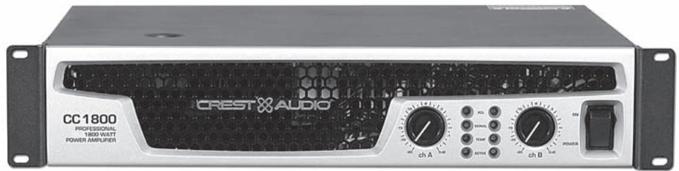
CC™ Series
1800
| Rated Power Bridge 4 ohms | 1850 watts @ 1 kHz at <0.1% T.H.D. |
| Rated Power (2 x 2 ohms) | 900 watts per channel @ 1 kHz <0.05% T.H.D. both channels driven |
| Rated Power (2 x 4 ohms) | 700 watts per channel @ 1 kHz at <0.05% T.H.D. both channels driven |
| Rated Power (2 x 8 ohms) | 450 watts per channel @ 1 kHz at <0.05% T.H.D. both channels driven |
| Rated Power (1 x 2 ohms) | 950 watts @ 1 kHz at <0.05% T.H.D. |
| Rated Power (1 x 4 ohms) | 775 watts @ 1 kHz at <0.05% T.H.D. |
| Rated Power (1 x 8 ohms) | 475 watts @ 1 kHz at <0.05% T.H.D. |
Minimum Load Impedance 2 ohms
Maximum RMS Voltage Swing 73 volts
Frequency Response 10Hz - 100kHz; + 0, - 3dB at 1 watt
Power Bandwidth 10Hz - 50kHz; + 0, - 3dB at rated 4 ohm power
T.H.D. (2 x 2 ohms) <0.2% @ 700 watts per channel from 20 Hz to 20 kHz
T.H.D. (2 x 4 ohms) <0.1% @ 600 watts per channel from 20 Hz to 20 kHz
T.H.D. (2 x 8 ohms) <0.1% @ 425 watts per channel from 20 Hz to 20 kHz
Input CMRR >-75dB@1kHz
Voltage Gain x40 (32 dB) x20 (26 dB)
Crosstalk >-55 dB @ 1 kHz at rated power @ 8 ohms
Hum and Noise >-106 dB, "A" weighted referenced to rated power @ 8 ohms
Slew Rate >35V/us
Damping Factor (8 ohms) > 150:1 @ 20 Hz - 1 kHz at 8 ohms
Phase Response +6 to - 12 degrees from 20Hz to 20kHz
Input Sensitivity (x40) 1.32 volts +/- 3% for 1 kHz, 4 ohm rated power, 1.06 volts +/- 3% for 1 kHz, 2 ohm rated power
Input Impedance 15 k ohms, balanced
Current Draw @ 1/8 power 1,000 watts @ 2 ohms, 685 watts @ 4 ohms,
400 watts @ 8 ohms
Current Draw @ 1/3 power 2,340 watts @ 2 ohms, 1,650 watts @ 4 ohms, 1,000 watts @ 8 ohms
Cooling One back panel temperature dependant variable speed 80~mm DC fan
Controls 2 front panel attenuators, rear panel Mode switches
Indicator LEDs 2 ACLTM (automatic clip limiting), 2 Signal presence, 2 Active status, 2 Temp
Protection Thermal, DC, turn-on bursts, subsonic, incorrect loads
Connectors Combi XLR & 6.3 mm phone input, Speakon and 5-way Binding Post speaker output, 15 amp IEC mains connector
Construction 16 ga. steel with cast front panel
Dimensions 88.9mm× 482.6mm× 377.8mm + 31.8mm for rear support ears and connectors (3.5^ 19^ 14.875^ + 1.25^ )
Net Weight 14.8 kg (32.6 lbs.)
Gross Weight 15.9kg (35 lbs.)
All power measurements made at 120 VAC, power transformer cold. 2 ohm power is time limited by magnetic circuit breaker.
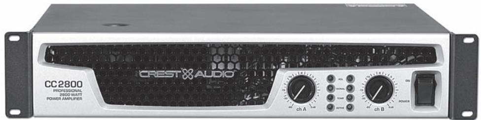
2800
| Rated Power Bridge 4 ohms | 2,800 watts @ 1 kHz at <0.1% T.H.D. |
| Rated Power (2 x 2 ohms) | 1,400 watts per channel @ 1 kHz <0.05% T.H.D. both channels driven |
| Rated Power (2 x 4 ohms) | 965 watts per channel @ 1 kHz at <0.05% T.H.D. both channels driven |
| Rated Power (2 x 8 ohms) | 595 watts per channel @ 1 kHz at <0.05% T.H.D. both channels driven |
| Rated Power (1 x 2 ohms) | 1,850 watts @ 1 kHz at <0.1% T.H.D. |
| Rated Power (1 x 4 ohms) | 1,150 watts @ 1 kHz at <0.05% T.H.D. |
| Rated Power (1 x 8 ohms) | 665 watts @ 1 kHz at <0.05% T.H.D. |
| Minimum Load Impedance | 2 ohms |
| Maximum RMS Voltage Swing | 82 volts |
| Frequency Response | 10 Hz - 100 kHz; +0, -2.0 dB at 1 watt |
| Power Bandwidth | 10 Hz - 35 kHz; +0, -3 dB at rated 4 ohm power |
| T.H.D. (2 x 2 ohms) | <0.15 @ 1,150 watts per channel from 20 Hz to 20 kHz |
| T.H.D. (2 x 4 ohms) | <0.1% @ 880 watts per channel from 20 Hz to 20 kHz |
| T.H.D. (2 x 8 ohms) | <0.1% @ 560 watts per channel from 20 Hz to 20 kHz |
| Input CMRR | > -65 dB @ 1 kHz |
| Voltage Gain | x40 (32 dB) x20 (26 dB) |
| Crosstalk | > -65 dB @ 1 kHz at rated power @ 8 ohms |
| Hum and Noise | > -111 dB, “A” weighted referenced to rated power @ 8 ohms |
| Slew Rate | > 15V/us |
| Damping Factor (8 ohms) | > 500:1 @ 20 Hz - 1 kHz |
| Phase Response | +5 to -15 degrees from 20 Hz to 20kHz |
| Input Sensitivity (x40) | 1.7 volts +/- 3% for 1 kHz, 4 ohm rated power, 1.36 volts +/- 3% for 1 kHz, 2 ohm rated power |
| Input Impedance | 15 k ohms, balanced |
| Current Draw @ 1/8 power | 1,250 watts @ 2 ohms, 880 watts @ 4 ohms, 570 @ 8 ohms |
| Current Draw @ 1/3 power | 2,905 watts @ 2 ohms, 2,220 watts @ 4 ohms, 1,355 watts @ 8 ohms |
| Cooling | Two back panel temperature dependant variable speed 80 mm DC fans |
| Controls | 2 front panel attenuators, rear panel Mode switches |
| Indicator LEDs | 2 ACLTM (automatic clip limiting), 2 Signal presence, 2 Active status, 2 Temp |
| Protection | Thermal, DC, turn-on bursts, subsonic, incorrect loads |
| Connectors | Combi XLR & 6.3 mm phone input, Speakon and 5-way Binding Post speaker output, 15 amp IEC mains connector |
| Construction | 16 ga. steel with cast front panel |
| Dimensions | 88.9 mm x 482.6 mm x 377.8 mm + 31.8 mm for rear support ears and connectors (3.5" x 19" x 14.875" + 1.25") |
| Net Weight | 18.05 kg (39.8 lbs.) |
| Gross Weight | 19.23 kg (42.4 lbs.) |
All power measurements made at 120 VAC, power transformer cold. 2 ohm power is time limited by magnetic circuit breaker.
4000
| Rated Power Bridge 4 ohms | 4,000 watts @ 1 kHz at <0.1% T.H.D. |
| Rated Power (2 x 2 ohms) | 2,000 watts per channel @ 1 kHz <0.1% T.H.D. both channels driven |
| Rated Power (2 x 4 ohms) | 1,350 watts per channel @ 1 kHz at <0.05% T.H.D. both channels driven |
| Rated Power (2 x 8 ohms) | 800 watts per channel @ 1 kHz at <0.05% T.H.D. both channels driven |
| Rated Power (1 x 2 ohms) | 2,550 watts @ 1 kHz at <0.1% T.H.D. |
| Rated Power (1 x 4 ohms) | 1,600 watts @ 1 kHz at <0.05% T.H.D. |
| Rated Power (1 x 8 ohms) | 900 watts @ 1 kHz at <0.05% T.H.D. |
| Minimum Load Impedance | 2 ohms |
| Maximum RMS Voltage Swing | 93 volts |
| Frequency Response | 10 Hz - 100 kHz; +0, -2 dB at 1 watt |
| Power Bandwidth | 10 Hz - 35 kHz; +0, -3 dB at rated 4 ohm power |
| T.H.D. (2 x 2 ohms) | <0.2% @ 1,475 watts per channel from 20 Hz to 20 kHz |
| T.H.D. (2 x 4 ohms) | <0.1% @ 1,150 watts per channel from 20 Hz to 20 kHz |
| T.H.D. (2 x 8 ohms) | <0.1% @ 700 watts per channel from 20 Hz to 20 kHz |
| Input CMRR | > -65 dB @ 1 kHz |
| Voltage Gain | x40 (32 dB) x20 (26 dB) |
| Crosstalk | > -65 dB @ 1 kHz at rated power @ 8 ohms |
| Hum and Noise | > -112 dB, “A” weighted referenced to rated power @ 8 ohms |
| Slew Rate | > 15V/us |
| Damping Factor (8 ohms) | > 500:1 @ 20 Hz - 1 kHz |
| Phase Response | +5 to -15 degrees from 20 Hz to 20 kHz |
| Input Sensitivity (x40) | 1.88 volts +/- 3% for 1 kHz, 4 ohm rated power, 1.62 volts +/- 3% for 1 kHz, 2 ohm rated power |
| Input Impedance | 15 k ohms, balanced |
| Current Draw @ 1/8 power | 1,825 watts @ 2 ohms, 1,185 watts @ 4 ohms, 720 @ 8 ohms |
| Current Draw @ 1/3 power | 4,535 watts @ 2 ohms, 2,975 watts @ 4 ohms, 1,835 watts @ 8 ohms |
| Cooling | Two back panel temperature dependant variable speed 80 mm DC fans |
| Controls | 2 front panel attenuators, rear panel Mode switches |
| Indicator LEDs | 2 ACLTM (automatic clip limiting), 2 Signal presence, 2 Active status, 2 Temp |
| Protection | Thermal, DC, turn-on bursts, subsonic, incorrect loads |
| Connectors | Combi XLR & 6.3 mm phone input, Speakon and 5-way Binding Post speaker output, 15 amp IEC mains connector |
| Construction | 16 ga. steel with cast front panel and cast handles |
| Dimensions | 88.9 mm x 482.6 mm x 377.8 mm + 31.8 mm for rear support ears and connectors (3.5" x 19" x 14.875" + 1.25") |
| Net Weight | 19.64 kg (43.3 lbs.) |
| Gross Weight | 20.8 kg.(45.8 lbs.) |
All power measurements made at 120 VAC, power transformer cold. 2 ohm power is time limited by magnetic circuit breaker.
| stranded cable length | wire gauge | power loss | ||
| 8Ω load | 4Ω load | 2Ω load | ||
| 2 meters | 0.3mm² | 2.9% | 5.6% | 10.8% |
| 0.5 | 1.74 | 3.4 | 6.7 | |
| 0.75 | 1.16 | 2.3 | 4.5 | |
| 1.5 | 0.58 | 1.16 | 2.3 | |
| 2.5 | 0.35 | 0.70 | 1.39 | |
| 4.0 | 0.22 | 0.44 | 0.87 | |
| 5 meters | 0.5mm² | 4.3% | 8.2% | 15.5% |
| 0.75 | 2.9 | 5.6 | 10.8 | |
| 1.5 | 1.45 | 2.9 | 5.6 | |
| 2.5 | 0.87 | 1.74 | 3.4 | |
| 4 | 0.55 | 1.09 | 2.2 | |
| 6 | 0.37 | 0.73 | 1.45 | |
| 10 meters | 0.5mm² | 8.24% | 5.5% | 28% |
| 0.75 | 5.6 | 10.8 | 19.9 | |
| 1.5 | 2.9 | 5.6 | 10.8 | |
| 2.5 | 1.74 | 2.9 | 6.7 | |
| 4 | 1.09 | 1.74 | 4.3 | |
| 6 | 0.73 | 1.09 | 2.9 | |
| 30 meters | 0.75mm² | 15.5% | 0.73% | 45% |
| 1.5 | 8.2 | 15.5 | 28 | |
| 2.5 | 5.1 | 9.8 | 18.2 | |
| 4 | 3.2 | 6.3 | 12.0 | |
| 6 | 2.2 | 4.3 | 8.2 | |
| 10 | 1.31 | 2.6 | 5.1 | |
| 5 feet | 18AWG | 0.81% | 1.61% | 3.2% |
| 16 | 0.51 | 1.02 | 2.0 | |
| 14 | 0.32 | 0.64 | 1.28 | |
| 12 | 0.20 | 0.40 | 0.80 | |
| 10 | 0.128 | 0.25 | 0.51 | |
| 10 feet | 18AWG | 1.61% | 3.2% | 6.2% |
| 16 | 1.02 | 2.0 | 4.0 | |
| 14 | 0.64 | 1.28 | 2.5 | |
| 12 | 0.40 | 0.80 | 1.60 | |
| 10 | 0.25 | 0.51 | 1.01 | |
| 40 feet | 18AWG | 6.2% | 11.9% | 22% |
| 16 | 4.0 | 7.7 | 14.6 | |
| 14 | 2.5 | 5.0 | 9.6 | |
| 12 | 1.60 | 3.2 | 6.2 | |
| 10 | 1.01 | 2.0 | 4.0 | |
| 8 | 0.60 | 1.20 | 2.4 | |
| 80 feet | 18AWG | 11.9% | 22% | 37% |
| 16 | 7.7 | 14.6 | 26 | |
| 14 | 5.0 | 9.6 | 17.8 | |
| 12 | 3.2 | 6.2 | 11.8 | |
| 10 | 2.0 | 4.0 | 7.7 | |
| 8 | 1.20 | 2.4 | 4.7 | |
E-Mail customerservice@crestaudio.com
Informations services
email customerserve@crestaudio.com
Service technique
Telephone 866.812.7378 USA
Fax 601.486.1380 USA
email techserve@crestaudio.com
web site
www.crestaudio.com
Courrier
Crest Audio Inc.
711 A Street
Meridian, MS 39301 USA
email customerserve@crestaudio.com
Entrada CMRR >-75dB a 1 kHz
Ganancia de Voltaje x40 (32 dB) x20 (26 dB)