
MXZ-4E83VA - Multi-split air conditioner MITSUBISHI - Free user manual and instructions
Find the device manual for free MXZ-4E83VA MITSUBISHI in PDF.
| Product Type | Multi-split air conditioner (outdoor unit) |
| Brand | MITSUBISHI |
| Model | MXZ-4E83VA |
| Number of connectable indoor units | 4 (A to D) |
| Power supply | 230 V ~ 50 Hz, 25 A (recommended circuit breaker) |
| Circuit breaker rating | 25 A |
| Refrigerant | R410A |
| Dimensions (H × W × D) | 950 × 600 × 330 mm |
| Noise level (cooling / heating) | 49 dB(A) / 51 dB(A) |
| Maximum piping length per indoor unit | 25 m |
| Maximum total piping length | 70 m |
| Maximum height difference between units | 15 m (10 m if outdoor unit is higher) |
| Maximum number of bends per indoor unit | 25 |
| Pipe diameters (liquid/gas) | 6.35 mm (1/4") / 12.7 mm (1/2") |
| Required clearance around unit | 100 mm minimum, 500 mm on the blower side |
| Special functions | Mode lock (cool/dry or heat), noise reduction, automatic wiring/piping correction |
| Included accessories | Drain socket, 5 drain caps |
| Parts to be supplied on site | Power cable (3×2.5 mm²), indoor/outdoor connection cable (4×1.0/1.5 mm²), pipes, insulation, etc. |
| Maintenance | Regular cleaning of fins and surrounding area, leak check |
| Safety | Installation by a professional, mandatory grounding, residual current circuit breaker, exclusive use of R410A refrigerant |
| Repairability | Contact a certified installer; spare parts available through the Mitsubishi network |
Frequently Asked Questions - MXZ-4E83VA MITSUBISHI
User questions about MXZ-4E83VA MITSUBISHI
0 question about this device. Answer the ones you know or ask your own.
Ask a new question about this device
Download the instructions for your Multi-split air conditioner in PDF format for free! Find your manual MXZ-4E83VA - MITSUBISHI and take your electronic device back in hand. On this page are published all the documents necessary for the use of your device. MXZ-4E83VA by MITSUBISHI.
USER MANUAL MXZ-4E83VA MITSUBISHI
Split-type Air-Conditioner
MXZ-4E83VA
MXZ-5E102VA
MXZ-2E53VAHZ
English is original.
- This manual only describes the installation of outdoor unit. When installing the indoor unit, refer to the installation manual of indoor unit.
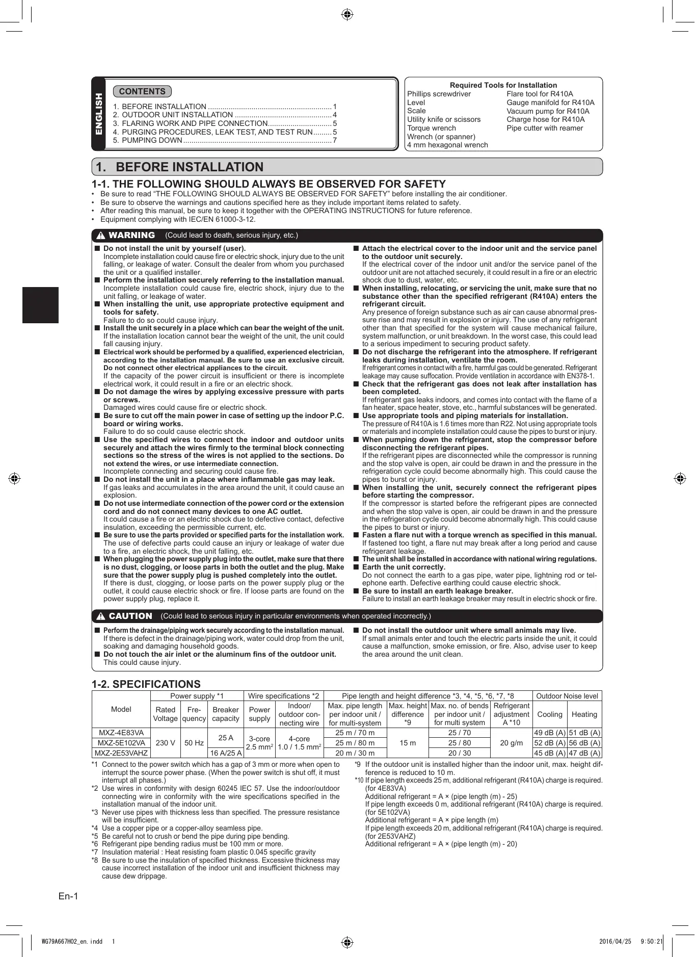
Required Tools for Installation
Phillips screwdriver
Flare tool for R410A
Level
Gauge manifold for R410A
Scale
Vacuum pump for R410A
Utility knife or scissors
Charge hose for R410A
Torque wrench
Pipe cutter with reamer
Wrench (or spanner)
4 mm hexagonal wrench
1. BEFORE INSTALLATION
1-1. THE FOLLOWING SHOULD ALWAYS BE OBSERVED FOR SAFETY
- Be sure to read "THE FOLLOWING SHOULD ALWAYS BE OBSERVED FOR SAFETY" before installing the air conditioner.
- Be sure to observe the warnings and cautions specified here as they include important items related to safety.
• After reading this manual, be sure to keep it together with the OPERATING INSTRUCTIONS for future reference.
• Equipment complying with IEC/EN 61000-3-12.
WARNING (Could lead to death, serious injury, etc.)
■ Do not install the unit by yourself (user).
Incomplete installation could cause fire or electric shock, injury due to the unit falling, or leakage of water. Consult the dealer from whom you purchased the unit or a qualified installer.
■ Perform the installation securely referring to the installation manual. Incomplete installation could cause fire, electric shock, injury due to the unit falling, or leakage of water.
■ When installing the unit, use appropriate protective equipment and tools for safety.
Failure to do so could cause injury.
■ Install the unit securely in a place which can bear the weight of the unit. If the installation location cannot bear the weight of the unit, the unit could fall causing injury.
■ Electrical work should be performed by a qualified, experienced electrician, according to the installation manual. Be sure to use an exclusive circuit. Do not connect other electrical appliances to the circuit.
If the capacity of the power circuit is insufficient or there is incomplete electrical work, it could result in a fire or an electric shock.
- Do not damage the wires by applying excessive pressure with parts or screws.
Damaged wires could cause fire or electric shock.
■ Be sure to cut off the main power in case of setting up the indoor P.C. board or wiring works.
Failure to do so could cause electric shock.
■ Use the specified wires to connect the indoor and outdoor units securely and attach the wires firmly to the terminal block connecting sections so the stress of the wires is not applied to the sections. Do not extend the wires, or use intermediate connection.
Incomplete connecting and securing could cause fire.
■ Do not install the unit in a place where inflammable gas may leak.
If gas leaks and accumulates in the area around the unit, it could cause an explosion.
- Do not use intermediate connection of the power cord or the extension cord and do not connect many devices to one AC outlet. It could cause a fire or an electric shock due to defective contact, defective insulation, exceeding the permissible current, etc.
■ Be sure to use the parts provided or specified parts for the installation work. The use of defective parts could cause an injury or leakage of water due to a fire, an electric shock, the unit falling, etc.
■ When plugging the power supply plug into the outlet, make sure that there is no dust, clogging, or loose parts in both the outlet and the plug. Make sure that the power supply plug is pushed completely into the outlet. If there is dust, clogging, or loose parts on the power supply plug or the outlet, it could cause electric shock or fire. If loose parts are found on the power supply plug, replace it.
■ Attach the electrical cover to the indoor unit and the service panel to the outdoor unit securely.
If the electrical cover of the indoor unit and/or the service panel of the outdoor unit are not attached securely, it could result in a fire or an electric shock due to dust, water, etc.
■ When installing, relocating, or servicing the unit, make sure that no substance other than the specified refrigerant (R410A) enters the refrigerant circuit.
Any presence of foreign substance such as air can cause abnormal pressure rise and may result in explosion or injury. The use of any refrigerant other than that specified for the system will cause mechanical failure, system malfunction, or unit breakdown. In the worst case, this could lead to a serious impediment to securing product safety.
- Do not discharge the refrigerant into the atmosphere. If refrigerant leaks during installation, ventilate the room.
If refrigerant comes in contact with a fire, harmful gas could be generated. Refrigerant leakage may cause suffocation. Provide ventilation in accordance with EN378-1.
- Check that the refrigerant gas does not leak after installation has been completed.
If refrigerant gas leaks indoors, and comes into contact with the flame of a fan heater, space heater, stove, etc., harmful substances will be generated.
■ Use appropriate tools and piping materials for installation.
The pressure of R410A is 1.6 times more than R22. Not using appropriate tools or materials and incomplete installation could cause the pipes to burst or injury.
■ When pumping down the refrigerant, stop the compressor before disconnecting the refrigerant pipes.
If the refrigerant pipes are disconnected while the compressor is running and the stop valve is open, air could be drawn in and the pressure in the refrigeration cycle could become abnormally high. This could cause the pipes to burst or injury.
■ When installing the unit, securely connect the refrigerant pipes before starting the compressor.
If the compressor is started before the refrigerant pipes are connected and when the stop valve is open, air could be drawn in and the pressure in the refrigeration cycle could become abnormally high. This could cause the pipes to burst or injury.
■ Fasten a flare nut with a torque wrench as specified in this manual. If fastened too tight, a flare nut may break after a long period and cause refrigerant leakage.
■ The unit shall be installed in accordance with national wiring regulations.
■ Earth the unit correctly.
Do not connect the earth to a gas pipe, water pipe, lightning rod or telephone earth. Defective earthing could cause electric shock.
■ Be sure to install an earth leakage breaker.
Failure to install an earth leakage breaker may result in electric shock or fire.
CAUTION (Could lead to serious injury in particular environments when operated incorrectly.)
■ Perform the drainage/piping work securely according to the installation manual. If there is defect in the drainage/piping work, water could drop from the unit, soaking and damaging household goods.
- Do not touch the air inlet or the aluminum fins of the outdoor unit. This could cause injury.
■ Do not install the outdoor unit where small animals may live.
If small animals enter and touch the electric parts inside the unit, it could cause a malfunction, smoke emission, or fire. Also, advise user to keep the area around the unit clean.
1-2. SPECIFICATIONS
| Model | Power supply *1 | Wire specifications *2 | Pipe length and height difference *3, *4, *5, *6, *7, *8 | Outdoor Noise level | |||||||
| Rated Voltage | Fre-quency | Breaker capacity | Power supply | Indoor/outdoor con-necting wire | Max. pipe length per indoor unit / for multi-system | Max. height difference *9 | Max. no. of bends per indoor unit / for multi system | Refrigerant adjustment A *10 | Cooling | Heating | |
| MXZ-4E83VA | 230 V | 50 Hz | 25 A | 3-core 2.5 mm2 | 4-core 1.0 / 1.5 mm2 | 25 m / 70 m | 15 m | 25 / 70 | 20 g/m | 49 dB (A) | 51 dB (A) |
| MXZ-5E102VA | 25 m / 80 m | 25 / 80 | 52 dB (A) | 56 dB (A) | |||||||
| MXZ-2E53VAHZ | 16 A/25 A | 20 m / 30 m | 20 / 30 | 45 dB (A) | 47 dB (A) | ||||||
*1 Connect to the power switch which has a gap of 3 mm or more when open to interrupt the source power phase. (When the power switch is shut off, it must interrupt all phases.)
*2 Use wires in conformity with design 60245 IEC 57. Use the indoor/outdoor connecting wire in conformity with the wire specifications specified in the installation manual of the indoor unit.
*3 Never use pipes with thickness less than specified. The pressure resistance will be insufficient.
*4 Use a copper pipe or a copper-alloy seamless pipe.
*5 Be careful not to crush or bend the pipe during pipe bending.
*6 Refrigerant pipe bending radius must be 100 mm or more.
*7 Insulation material : Heat resisting foam plastic 0.045 specific gravity
*8 Be sure to use the insulation of specified thickness. Excessive thickness may cause incorrect installation of the indoor unit and insufficient thickness may cause dew drippage.
*9 If the outdoor unit is installed higher than the indoor unit, max. height difference is reduced to 10 m.
*10 If pipe length exceeds 25 m, additional refrigerant (R410A) charge is required. (for 4E83VA)
Additional refrigerant = A × (pipe length (m) - 25)
If pipe length exceeds 0 m, additional refrigerant (R410A) charge is required. (for 5E102VA)
Additional refrigerant = A × pipe length (m)
If pipe length exceeds 20 m, additional refrigerant (R410A) charge is required. (for 2E53VAHZ)
Additional refrigerant = A × (pipe length (m) - 20)
1-3. SELECTING OPTIONAL DIFFERENT-DIAMETER JOINTS
If the diameter of connection pipe does not match the port size of outdoor unit, use optional different-diameter joints according to the following table.
(Unit: mm (inch))
| Port size of outdoor unit | Optional different-diameter joints (port size of outdoor unit → diameter of connection pipe) | |||
| MXZ-2E53VAHZ | MXZ-4E83VA | MXZ-5E102VA | Liquid / Gas | 6.35 (1/4) → 9.52 (3/8) : PAC-493PI9.52 (3/8) → 12.7 (1/2) : MAC-A454JP9.52 (3/8) → 15.88 (5/8) : PAC-SG76RJ12.7 (1/2) → 9.52 (3/8) : MAC-A455JP12.7 (1/2) → 15.88 (5/8) : MAC-A456JPRefer to the installation manual of indoor unit for the diameter of connection pipe of indoor unit. |
| - | A UNIT | 6.35 (1/4) / 12.7 (1/2) | ||
| A - B UNIT | B - D UNIT | B - E UNIT | 6.35 (1/4) / 9.52 (3/8) | |
1-4. SELECTING THE INSTALLATION LOCATION
• Where it is not exposed to strong wind.
• Where airflow is good and dustless.
- Where rain or direct sunshine can be avoided as much as possible.
- Where neighbours are not annoyed by operation sound or hot air.
- Where rigid wall or support is available to prevent the increase of operation sound or vibration.
• Where there is no risk of combustible gas leakage.
- When installing the unit, be sure to secure the unit legs.
- Where it is at least 3 m away from the antenna of TV set or radio. Operation of the air conditioner may interfere with radio or TV reception in areas where reception is weak. An amplifier may be required for the affected device.
• Install the unit horizontally.
- Please install it in an area not affected by snowfall or blowing snow. In areas with heavy snow, please install a canopy, a pedestal and/or some baffle boards.
Note:
It is advisable to make a piping loop near outdoor unit so as to reduce vibration transmitted from there.
Note:
When operating the air conditioner in low outside temperature, be sure to follow the instructions described below.
- Never install the outdoor unit in a place where its air inlet/outlet side may be exposed directly to wind.
- To prevent exposure to wind, install the outdoor unit with its air inlet side facing the wall.
- To prevent exposure to wind, it is recommended to install a baffle board on the air outlet side of the outdoor unit.
Avoid the following places for installation where air conditioner trouble is liable to occur.
• Where flammable gas could leak.
• Where there is much machine oil.
- Where oil is splashed or where the area is filled with oily smoke (such as cooking areas and factories, in which the properties of plastic could be changed and damaged).
- Salty places such as the seaside.
- Where sulfide gas is generated such as a hot spring, sewage, waste water.
- Where there is high-frequency or wireless equipment.
- Where there is emission of high levels of VOCs, including phthalate compounds, formaldehyde, etc., which may cause chemical cracking.
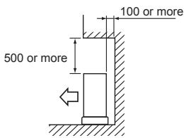
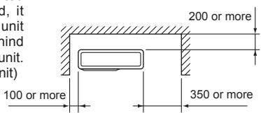
FREE SPACE REQUIRED AROUND OUTDOOR UNIT
1. Obstacles above
When there is no obstacle in front and on the sides of the unit, it is allowed to install the unit where an obstacle is above the unit only if the space shown in the figure is provided.
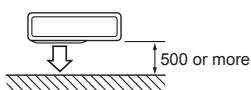
3. Obstacles in front (blowing) only
When there is an obstacle in front of the unit as shown in the figure, open space above, behind, and on the sides of the unit is required.
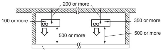
5. Obstacles in front, behind and on side(s)
- When installing the unit in an area that is enclosed with walls such as a verandah, be sure to have enough space as shown below. In this case, the air conditioning capacity and power consumption might deteriorate.
- When there is a lack of airflow or there is a possibility of becoming short cycle, install an outlet guide and make sure there is enough space behind of the unit.
- When installing two or more units, do not install the units in front or behind each other.
Height of the obstacle is 1200 or less
2. Front (blowing) side open
As long as space indicated in the figure is provided, it is allowed to install the unit where obstacles are behind and on the sides of the unit. (No obstacle above the unit)
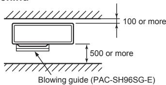
4. Obstacles in front and behind
The unit can be used by attaching an optional outdoor blowing guide (PAC-SH96SG-E) (but both sides and top are open).
6. Service space
Provide space for service and maintenance as shown in the figure.
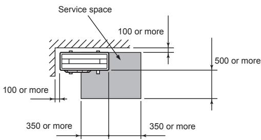
(Unit: mm)
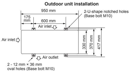
1-5. INSTALLATION DIAGRAM
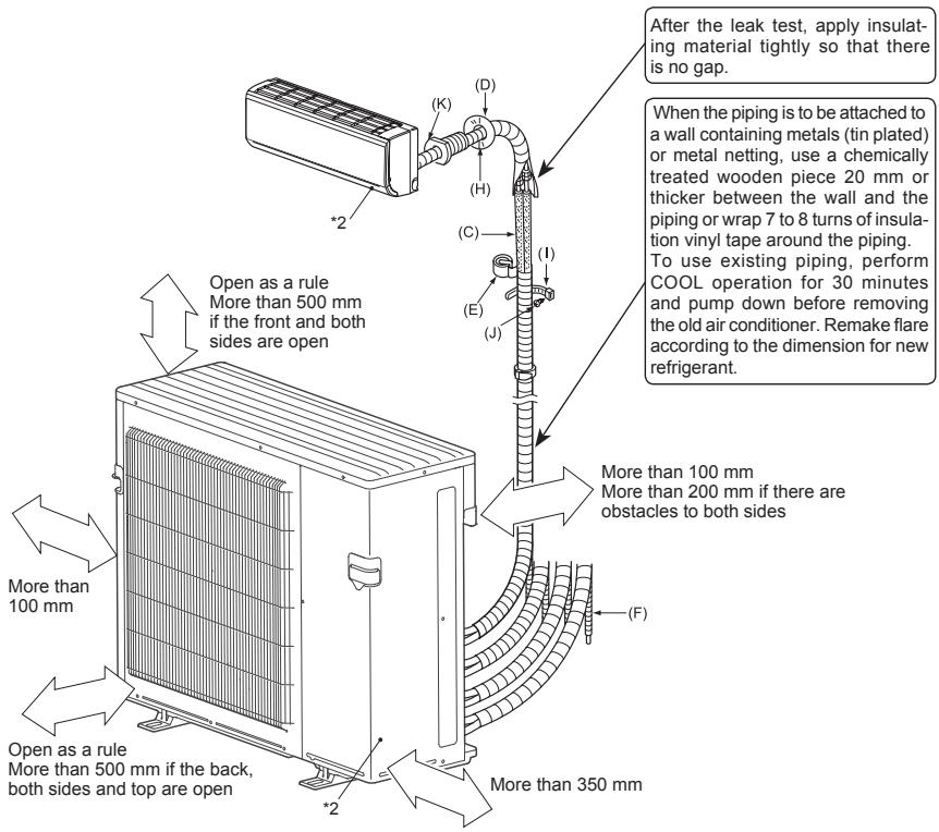
*2 The manufacturing year and month is indicated on the spec name plate.
ACCESSORIES (MXZ-4E83/5E102VA only)
Check the following parts before installation.
| (1) | Drain socket | 1 |
| (2) | Drain cap | 5 |
PARTS TO BE PROVIDED AT YOUR SITE
| (A) | Power supply cord*1 | 1 |
| (B) | Indoor/outdoor unit connecting wire*1 | 1 |
| (C) | Extension pipe | 1 |
| (D) | Wall hole cover | 1 |
| (E) | Piping tape | 1 |
| (F) | Extension drain hose (or soft PVC hose, 15 mm inner diameter or hard PVC pipe VP16) | 1 |
| (G) | Refrigeration oil | Little amount |
| (H) | Putty | 1 |
| (I) | Pipe fixing band | 2 to 7 |
| (J) | Fixing screw for (I) | 2 to 7 |
| (K) | Wall hole sleeve | 1 |
| (L) | Soft PVC hose, 15 mm inner diameter or hard PVC pipe VP16 for drain socket (1) | 1 |
Note:
*1 Place indoor/outdoor unit connecting wire (B) and power supply cord (A) at least 1 m away from the TV antenna wire.
The “Q'ty” for (B) to (K) in the above table is quantity to be used per indoor unit.
Units should be installed by licensed contractor according to local code requirements.
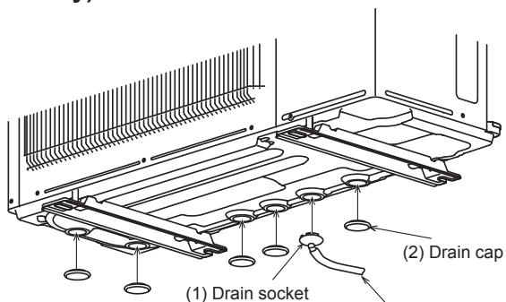
1-6. DRAIN PIPING FOR OUTDOOR UNIT (MXZ-4E83/5E102VA only)
1) Perform the drain piping work only when draining from one place.
2) Provide drain piping before indoor and outdoor piping connection.
3) Attach the drain socket to one of the several drain holes.
Fix the drain socket into the drain hole of the base using the catches to secure it in place.
4) Connect the soft PVC hose I.D.15 mm as shown in the illustration.
5) Make sure to provide drain piping with a downhill grade for easy drain flow.
6) Glue the drain caps to close all the other unnecessary holes with the glue (Prepare in the field).
Note:
Apply the glue securely, as the glue (Prepare in the field) will work as seal to prevent water from leaking.
Use the adhesive for the rubber and metal.
Attention
The outdoor unit is provided with several holes for drainage at the bottom to make drainage easier.
The drain socket is used to close the unnecessary holes and centralize the drainage when using the drain tube at the installation place.
Do not to use the drain socket in cold region. The drain tube can be frozen.
(L) Soft PVC hose
2. OUTDOOR UNIT INSTALLATION
2-1. INSTALLING THE UNIT
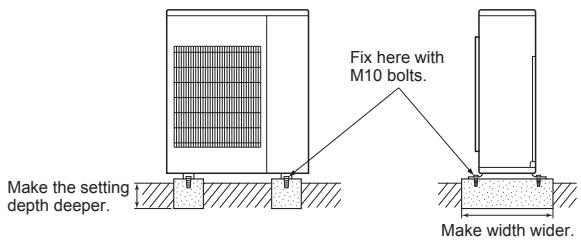
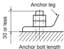
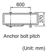
- Be sure to fix the unit's legs with bolts when installing it.
- Be sure to install the unit firmly to ensure that it does not fall by an earthquake or a gust.
• Refer to the figure in the right for concrete foundation. - Do not use the drain socket and the drain caps in the cold region.
Drain may freeze and it makes the fan stop. - Remove the tape on the panel when opening the package. (DO NOT remove the LABELS on the panel.)
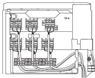
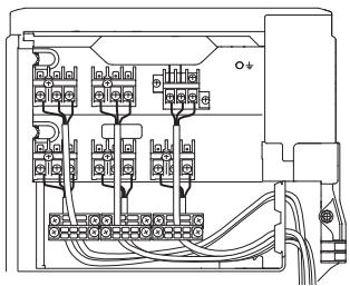
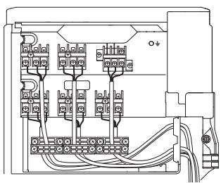
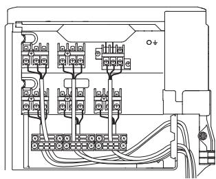
2-2. CONNECTING WIRES FOR OUTDOOR UNIT
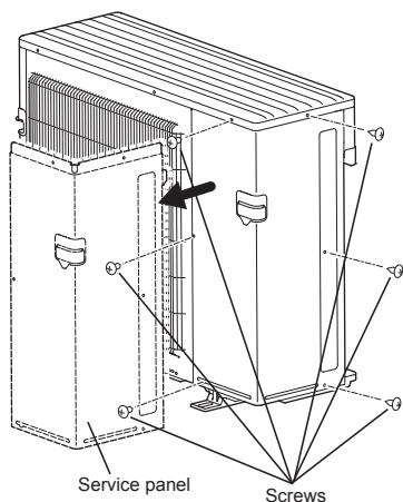
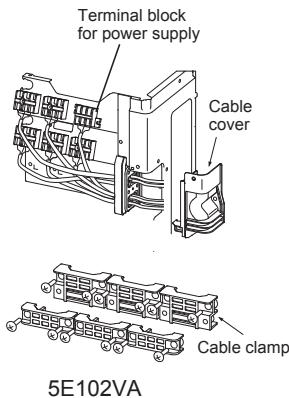
1) Remove the service panel and the cable cover.
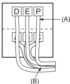
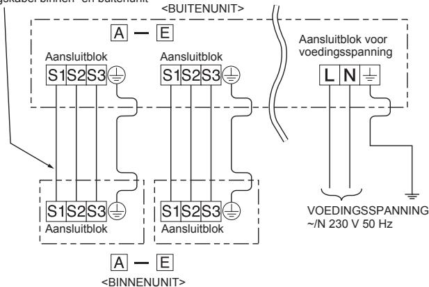
2) Pass the indoor/outdoor unit connecting wire (B) and power supply cord (A) through the grommet. Loosen terminal screw, and connect indoor/outdoor unit connecting wire (B) from the indoor unit correctly on the terminal block. Be careful not to make mis-wiring. Fix the wire to the terminal block securely so that no part of its core is appeared, and no external force is conveyed to the connecting section of the terminal block.
3) Firmly tighten the terminal screws to prevent them from loosening. After tightening, pull the wires lightly to confirm that they do not move.
4) Perform 2) and 3) for each indoor unit.
5) Connect power supply cord (A).
6) Fix indoor/outdoor unit connecting wire (B) and power supply cord (A) with the cable clamps. Route the cables or wires so as not to deform the service panel. Otherwise, rainwater may enter the outdoor unit.
7) Close the service panel and the cable cover securely. Make sure that 3-2. PIPE CONNECTION is completed.
- After making connections between both power supply cord (A) and indoor/outdoor unit connecting wire (B), be sure to fix both cable and wire with cable clamps.
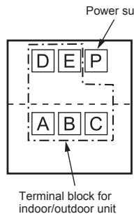
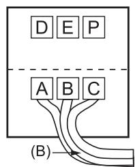
Connecting order
- Connect the terminal block in following order.
| MXZ-5E102VA | A→B→C→D→E→P |
| MXZ-4E83VA | A→B→C→D→P |
| MXZ-2E53VAHZ | A→B→P |
flowchart
graph TD
    A["A"] --> B["B"]
    C["C"] --> D["D"]
    E["E"] --> F["E"]
    G["F"] --> H["F"]
    I["..."] --> J["..."]
    style A fill:#fff,stroke:#000
    style B fill:#fff,stroke:#000
    style C fill:#fff,stroke:#000
    style D fill:#fff,stroke:#000
    style E fill:#fff,stroke:#000
    style F fill:#fff,stroke:#000
    style G fill:#fff,stroke:#000
    style H fill:#fff,stroke:#000
    style I fill:#fff,stroke:#000
→

flowchart
graph TD
    A["D"] --> B[" "]
    C["E"] --> B
    D["P"] --> B
    E["C"] --> B
    F["(B)"] --> G["Curved Path"]
    style A fill:#f9f,stroke:#333
    style C fill:#f9f,stroke:#333
    style D fill:#f9f,stroke:#333
    style E fill:#f9f,stroke:#333
    style F fill:#f9f,stroke:#333
→

natural_image
Electrical wiring diagram showing connections between components (no text or symbols)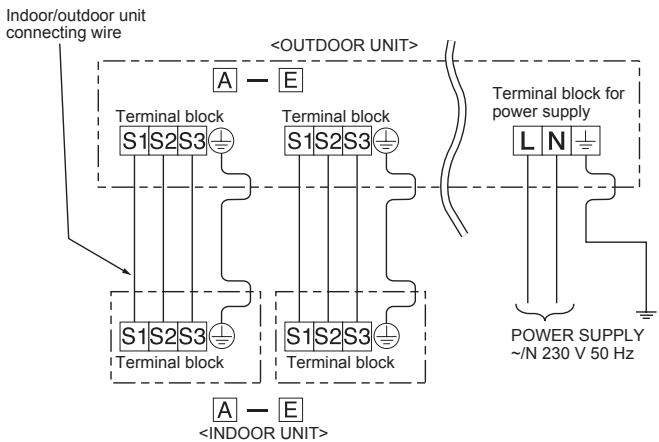
| Model | INDOOR / OUTDOOR UNIT |
| MXZ-5E102VA | A - E |
| MXZ-4E83VA | A - D |
| MXZ-2E53VAHZ | A - B |
- Be sure to attach each screw to its correspondent terminal when securing the cord and/or the wire to the terminal block.
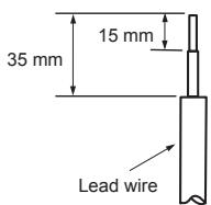
• Make earth wire a little longer than others. (More than 35 mm) - For future servicing, give extra length to the connecting wires.
3. FLARING WORK AND PIPE CONNECTION
3-1. FLARING WORK
1) Cut the copper pipe correctly with pipe cutter. (Fig. 1, 2)
2) Completely remove all burrs from the cut cross section of pipe. (Fig. 3)
- Aim the copper pipe downward while removing burrs to prevent burrs from dropping in the pipe.
3) Remove flare nuts attached to indoor and outdoor units, then put them on pipe having completed burr removal. (Not possible to put them on after flaring work.)
4) Flaring work (Fig. 4, 5). Firmly hold copper pipe in the dimension shown in the table. Select A mm from the table according to the tool selected.
5) Check
- Compare the flared work with Fig. 6.
- If flare is noted to be defective, cut off the flared section and do flaring work again.
| Pipe diameter (mm) | Nut (mm) | A (mm) | Tightening torque | |||
| Clutch type tool for R410A | Clutch type tool for R22 | Wing nut type tool for R22 | N•m | kgf•cm | ||
| 6.35 (1/4") | 17 | 0 to 0.5 | 1.0 to 1.5 | 1.5 to 2.0 | 13.7 to 17.7 | 140 to 180 |
| 9.52 (3/8") | 22 | 34.3 to 41.2 | 350 to 420 | |||
| 12.7 (1/2") | 26 | 2.0 to 2.5 | 49.0 to 56.4 | 500 to 575 | ||
| 15.88 (5/8") | 29 | 73.5 to 78.4 | 750 to 800 | |||
3-2. PIPE CONNECTION
1) Apply a thin coat of refrigeration oil (G) to the flared ends of the pipes and the pipe connections of the outdoor unit. Do not apply refrigeration oil on screw threads. Excessive tightening torque will result in damage on the screw.
2) Align the center of the pipe with that of the pipe connections of the outdoor unit, then hand tighten the flare nut 3 to 4 turns.
3) Tighten the flare nut with a torque wrench as specified in the table.
• Over-tightening may cause damage to the flare nut, resulting in refrigerant leakage.
- Be sure to wrap insulation around the piping. Direct contact with the bare piping may result in burns or frostbite.
3-3. INSULATION AND TAPING
1) Cover piping joints with pipe cover.
2) For outdoor unit side, surely insulate every piping including valves.
3) Using piping tape (E), apply taping starting from the entry of outdoor unit.
- Stop the end of piping tape (E) with tape (with adhesive agent attached).
- When piping have to be arranged through above ceiling, closet or where the temperature and humidity are high, wind additional commercially sold insulation to prevent condensation.
| Fig. 1 Copper pipe Burr Copper pipe Spare reamer Pipe cutter | Fig. 2 No good 90° Tilted Uneven Burred |
| Fig. 3 Flare nut | Fig. 4 Flaring tool Clutch type Wing nut type |
| Fig. 5 A Die Flare nut | Fig. 6 Inside is shining without any scratches. Even length all around |
WARNING
When installing the unit, securely connect the refrigerant pipes before starting the compressor.
natural_image
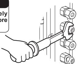
Illustration of a hand using a wrench to tighten bolted joint (no text or symbols present)CAUTION
When there are the ports which are not used, make sure their nuts are tightened securely.
4. PURGING PROCEDURES, LEAK TEST, AND TEST RUN
4-1. PURGING PROCEDURES AND LEAK TEST
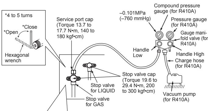
1) Remove service port cap of stop valve on the side of the outdoor unit gas pipe. (The stop valves are fully closed and covered in caps in their initial state.)
2) Connect gauge manifold valve and vacuum pump to service port of stop valve on the gas pipe side of the outdoor unit.
3) Run the vacuum pump. (Vacuumize for more than 15 minutes.)
4) Check the vacuum with gauge manifold valve, then close gauge manifold valve, and stop the vacuum pump.
5) Leave as it is for one or two minutes. Make sure the pointer of gauge manifold valve remains in the same position. Confirm that pressure gauge shows -0.101 MPa [Gauge] (-760 mmHg).
6) Remove gauge manifold valve quickly from service port of stop valve.
7) Fully open all stop valves on the gas pipe and the liquid pipe. Operating without fully opening lowers the performance and this causes trouble.
8) Refer to 1-2., and charge the prescribed amount of refrigerant if needed. Be sure to charge slowly with liquid refrigerant. Otherwise, composition of the refrigerant in the system may be changed and affect performance of the air conditioner.
9) Tighten cap of service port to obtain the initial status.
10) Leak test
Precautions when using the control valve
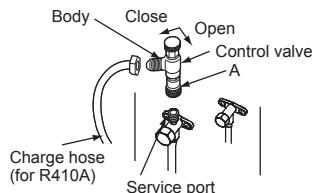
When attaching the control valve to the service port, valve core may deform or loosen if excess pressure is applied. This may cause gas leak.
When attaching the control valve to the service port, make sure that the valve core is in closed position, and then tighten part A. Do not tighten part A or turn the body when valve core is in open position.
4-2. GAS CHARGE
Perform gas charge to unit.
1) Connect gas cylinder to the service port of stop valve.
2) Perform air purge of the pipe (or hose) coming from refrigerant gas cylinder.
3) Replenish specified amount of the refrigerant, while operating the air conditioner for cooling.
Note:
In case of adding refrigerant, comply with the quantity specified for the refrigerating cycle.
CAUTION:
When charging the refrigerant system with additional refrigerant, be sure to use liquid refrigerant. Adding gas refrigerant may change the composition of the refrigerant in the system and affect normal operation of the air conditioner. Also, charge the liquid refrigerant slowly, otherwise the compressor will be locked.
To maintain the high pressure of the gas cylinder, warm the gas cylinder with warm water (under 40^ C) during cold season. But never use naked fire or steam.
| Model | Indoor unit |
| MXZ-5E102VA | A - E |
| MXZ-4E83VA | A - D |
| MXZ-2E53VAHZ | A - B |
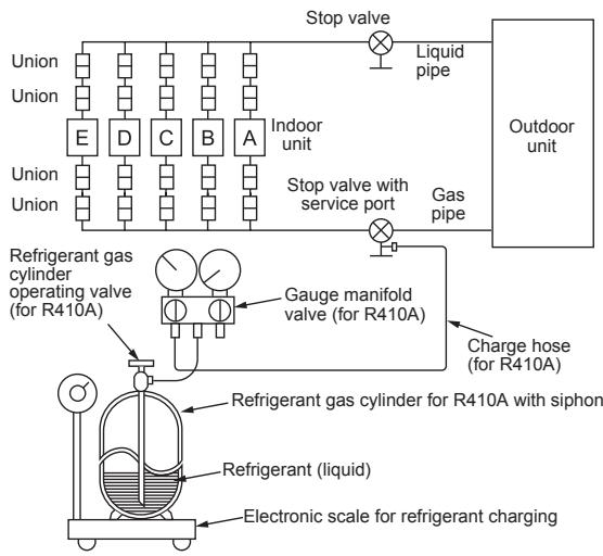
flowchart
graph TD
    A["Refrigerant gas cylinder operating valve (for R410A)"] --> B["Refrigerant gas cylinder for R410A with siphon"]
    B --> C["Gauge manifold valve (for R410A)"]
    C --> D["Stop valve with service port"]
    D --> E["Liquid pipe"]
    E --> F["Outdoor unit"]
    G["Electronic scale for refrigerant charging"] --> H["Refrigerant (liquid)"]
    H --> I["Union"]
    H --> J["Union"]
    H --> K["Union"]
    H --> L["Union"]
    H --> M["Union"]
    H --> N["Indoor unit"]
    N --> O["Stop valve with service port"]
    O --> P["Gas pipe"]
4-3. LOCKING THE OPERATION MODE OF THE AIR CONDITIONER (COOL, DRY, HEAT)
• Description of the function:
With this function, once the operation mode is locked to either COOL/DRY mode or HEAT mode, the air conditioner operates in that mode only.
* Changing the setting is required to activate this function. Please explain about this function to your customers and ask them whether they want to use it.
[How to lock the operation mode]
1) Be sure to turn off the main power for the air conditioner before making the setting.
2) Set the "3" of SW1 on the outdoor controller board to ON to enable this function.
3) To lock the operation mode in COOL/DRY mode, set the "4" of SW1 on the outdoor controller board to OFF. To lock the operation in HEAT mode, set the same switch to ON.
4) Turn on the main power for the air conditioner.
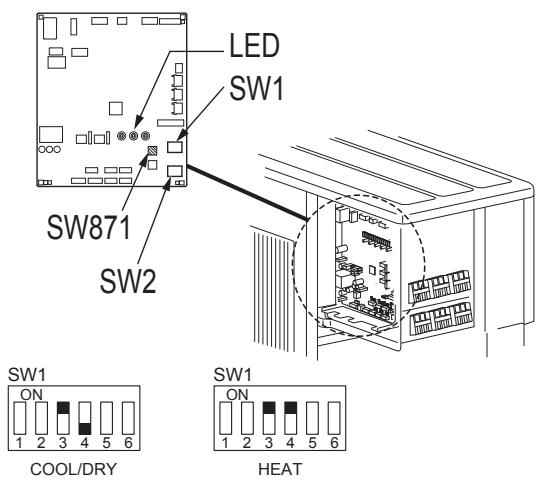
4-4. LOWERING THE OPERATION NOISE OF THE OUTDOOR UNIT
• Description of the function:
With this function, the operating noise of the outdoor unit can be lowered by reducing the operation load, for example, during nighttime in COOL mode. However, please note that the cooling and heating capacity may lower if this function is activated.
* Changing the setting is required to activate this function. Please explain about this function to your customers and ask them whether they want to use it.
[How to lower the operating noise]
1) Be sure to turn off the main power for the air conditioner before making the setting.
2) Set the "5" of SW1 on the outdoor controller board to ON to enable this function.
3) Turn on the main power for the air conditioner.
![MITSUBISHI MXZ-4E83VA - [How to lower the operating noise] - 1](/content/2020/11/207837/images/47be3688e177c865aee8b8a5a8ad9eff7ecc36d76c004dad8094306fc4804e32.jpg)
Lower the operating noise
4-5. CHANGING THE AMPERE LIMIT
• Description of the function:
With this function, the amount of current that flows in the outdoor unit can be changed.
Note:
Use this function only when the amount of current exceeds the allowed value.
[How to change the ampere limit]
1) Be sure to turn off the main power for the air conditioner before making the setting.
2) Make the setting referring to the table below.
3) Turn on the main power for the air conditioner.
| SW2 | MXZ-2E53VAHZ |
| 13.6 A | |
| 18.4 A |
4-6. TEST RUN
- Test runs of the indoor units should be performed individually. See the installation manual coming with the indoor unit, and make sure all the units operate properly.
- If the test run with all the units is performed at once, possible erroneous connections of the refrigerant pipes and the indoor/outdoor unit connecting wires cannot be detected. Thus, be sure to perform the test run one by one.
About the restart protective mechanism
Once the compressor stops, the restart preventive device operates so the compressor will not operate for 3 minutes to protect the air conditioner.
Wiring/piping correction function
This unit has a wiring/piping correction function which corrects wiring and piping combination. When there is possibility of incorrect wiring and piping combination, and confirming the combination is difficult, use this function to detect and correct the combination by following the procedures below.
Make sure that the following is done.
• Power is supplied to the unit.
- Stop valves are open.
Note:
During detection, the operation of the indoor unit is controlled by the outdoor unit. During detection, the indoor unit automatically stops operation. This is not a malfunction.
Procedure
Press the piping/wiring correction switch (SW871) 1 minute or more after turning on the power supply.
- Correction completes in 10 to 20 minutes. When the correction is completed, its result is shown by LED indication. Details are described in the following table.
- To cancel this function during its operation, press the piping/wiring correction switch (SW871) again.
- When the correction completed without error, do not press the piping/wiring correction switch (SW871) again.
When the result is “Not completed”, press the piping/wiring correction switch (SW871) again to cancel this function. Then, confirm the wiring and piping combination in a conventional manner by operating the indoor units one by one.
- The operation is done while the power is supplied. Make sure not to contact parts other than the switch, including the P.C. board. This may cause electric shock or burn by hot parts and live parts around the switch. Contacting the live parts may cause P.C. board damage.
- To prevent electronic control P.C. board damage, make sure to perform static elimination before operating this function.
- This function does not operate when the outside temperature is 0^ or below.
LED indication during detection:
| LED1(Red) | LED2(Yellow) | LED3(Green) |
| Lighted | Lighted | Once |
Result of piping/wiring correction function
| LED1 (Red) | LED2 (Yellow) | LED3 (Green) | Result |
| Lighted | Not lighted | Lighted | Completed (Problem corrected or normal) |
| Once | Once | Once | Not completed (Detection failed) |
| Other indications | Refer to “SAFETY PRE-CAUTIONS WHEN LED BLINKS” located behind the service panel. | ||
4-7. EXPLANATION TO THE USER
- Using the OPERATING INSTRUCTIONS, explain to the user how to use the air conditioner (how to use the remote controller, how to remove the air filters, how to remove or put the remote controller in the remote controller holder, how to clean, precautions for operation, etc.).
- Recommend the user to read the OPERATING INSTRUCTIONS carefully.
5. PUMPING DOWN
When relocating or disposing of the air conditioner, pump down the system following the procedure below so that no refrigerant is released into the atmosphere.
1) Turn off the breaker.
2) Connect the gauge manifold valve to the service port of the stop valve on the gas pipe side of the outdoor unit.
3) Fully close the stop valve on the liquid pipe side of the outdoor unit.
4) Turn on the breaker.
5) Start the emergency COOL operation on all the indoor units.
6) When the pressure gauge shows 0 – 0.05 MPa [Gauge] (approx. 0 – 0.5 kgf/cm ^2 ), fully close the stop valve on the gas pipe side of the outdoor unit and stop the operation. (Refer to the indoor unit installation manual about the method for stopping the operation.)
* If too much refrigerant has been added to the air conditioner system, the pressure may not drop to 0 – 0.05 MPa [Gauge] (approx. 0 – 0.5 kgf/cm ^2 ), or the protection function may operate due to the pressure increase in the high-pressure refrigerant circuit. If this occurs, use a refrigerant collecting device to collect all of the refrigerant in the system, and then recharge the system with the correct amount of refrigerant after the indoor and outdoor units have been relocated.
7) Turn off the breaker. Remove the pressure gauge and the refrigerant piping.
WARNING
When pumping down the refrigerant, stop the compressor before disconnecting the refrigerant pipes. The compressor may burst and cause injury if any foreign substance, such as air, enters the pipes.
DEUTSCH
INHALT
- VOR DER INSTALLATION....1
- INSTALLATION DES AUSSENGERÂTES....4
- LÖTARBEITEN UND ROHRANSCHLÜSSE......5
- SPÜLPROZEDUREN, LECKTEST UND TESTLAUF .....5
- LEERPUMPEN 7
natural_image
Electrical wiring diagram showing connections between components (no text or labels)(B)
natural_image
Pure electrical circuit lines without any symbols(Eenheid: mm (inch))
| Openingsgrootte van de buitenunit | Optionele verloopstukken (openingsgrootte van de buitenunit → diameter van de verbindingsleiding) | |||
| MXZ-2E53VAHZ | MXZ-4E83VA | MXZ-5E102VA | Vloeibaar / gas | 6,35 (1/4) → 9,52 (3/8) : PAC-493PI9,52 (3/8) → 12,7 (1/2) : MAC-A454JP9,52 (3/8) → 15,88 (5/8) : PAC-SG76RJ12,7 (1/2) → 9,52 (3/8) : MAC-A455JP12,7 (1/2) → 15,88 (5/8) : MAC-A456JPRaadpleeg de installatiehandleiding van de binnenunit voor de diameter van de verbindingsleiding van de binnenunit. |
| – | UNIT A | 6,35 (1/4) / 12,7 (1/2) | ||
| UNIT A - B | UNIT B - D | UNIT B - E | 6,35 (1/4) / 9,52 (3/8) | |
1-4. BEPALEN VAN DE INSTALLATIEPLAATS
natural_image
Electrical wiring diagram showing connections between components (no text or symbols)Verbindingskabel binnen- en buitenunit
(B)

natural_image
Pure electrical circuit lines without any symbols! CUIDADO
ACCESSORI (solo MXZ-4E83/5E102VA)
(B)
natural_image
Electrical wiring diagram showing connections between components (no text or symbols)(B)

natural_image
Pure electrical circuit lines without any symbolsDELAR SOM SKA FINNAS TILL HANDS PÅ PLATSEN
(B)

natural_image
Pure electrical circuit lines without any symbols(B)
natural_image
Electrical wiring diagram showing connections between components (no text or symbols)Mitsubishi Electric Corporation (Head Office)
Tokyo Building, 2-7-3, Marunouchi, Chiyoda-ku, Tokyo 100-8310, Japan
Tel: +81 (3) 3218-2111
www.mitsubishielectric.com
СЪДЪРЖАНИЕ
(B)
natural_image
Electrical wiring diagram showing connections between components (no text or labels)hereby declares under its sole responsibility that the air conditioners and heat pumps described below for use in residential, commercial and light-industrial environments:
Note: Its serial number is on the nameplate of the product.
2006/42/EC: Machinery Directive
2014/30/EU: Electromagnetic Compatibility Directive
2009/125/EC: Energy-related Products Directive and Regulation (EU) No 206/2012
2011/65/EU: RoHS Directive
Issued:
20 Apr. 2016
Takuo AKIYAMA
JAPAN
Manager, Quality Assurance Division
Importer:
Mitsubishi Electric Europe B.V.
Capronilaan 46, 1119 NS, Schiphol Rijk, The Netherlands
French Branch
25, Boulevard des Bouvets, 92741 Nanterre Cedex, France
German Branch
Mitsubishi-Electric-Platz 1, 40882 Ratingen, Germany
Belgian Branch
Autobaan 2, 8210 Loppem, Belgium
Irish Branch
Westgate Business Park, Ballymount, Dublin 24, Ireland
Italian Branch
Travellers Lane, Hatfield, Herts., AL10 8XB, England, U.K.
Polish Branch
Krakowska 50, PL-32-083 Balice, Poland
MITSUBISHI ELECTRIC TURKEY ELEKTRİK ÜRÜNLERİ A.Ş.
Şerifali Mah. Kale Sok. No: 41 34775 Ümraniye, İstanbul / Turkey
- Split-type Air-Conditioner
- Required Tools for Installation
- BEFORE INSTALLATION
- 1-1. THE FOLLOWING SHOULD ALWAYS BE OBSERVED FOR SAFETY
- WARNING (Could lead to death, serious injury, etc.)
- CAUTION (Could lead to serious injury in particular environments when operated incorrectly.)
- 1-3. SELECTING OPTIONAL DIFFERENT-DIAMETER JOINTS
- 1-4. SELECTING THE INSTALLATION LOCATION
- Note:
- FREE SPACE REQUIRED AROUND OUTDOOR UNIT
- Obstacles above
- Obstacles in front (blowing) only
- Obstacles in front, behind and on side(s)
- Front (blowing) side open
- Obstacles in front and behind
- Service space
- 1-5. INSTALLATION DIAGRAM
- 1-6. DRAIN PIPING FOR OUTDOOR UNIT (MXZ-4E83/5E102VA only)
- Attention
- OUTDOOR UNIT INSTALLATION
- 2-1. INSTALLING THE UNIT
- 2-2. CONNECTING WIRES FOR OUTDOOR UNIT
- FLARING WORK AND PIPE CONNECTION
- 3-1. FLARING WORK
- 3-2. PIPE CONNECTION
- 3-3. INSULATION AND TAPING
- WARNING
- CAUTION
- PURGING PROCEDURES, LEAK TEST, AND TEST RUN
- 4-1. PURGING PROCEDURES AND LEAK TEST
- 4-2. GAS CHARGE
- CAUTION:
- 4-3. LOCKING THE OPERATION MODE OF THE AIR CONDITIONER (COOL, DRY, HEAT)
- [How to lock the operation mode]
- 4-4. LOWERING THE OPERATION NOISE OF THE OUTDOOR UNIT
- [How to lower the operating noise]
- 4-5. CHANGING THE AMPERE LIMIT
- [How to change the ampere limit]
- 4-6. TEST RUN
- About the restart protective mechanism
- Wiring/piping correction function
- Procedure
- 4-7. EXPLANATION TO THE USER
- PUMPING DOWN
- DEUTSCH
- INHALT
- 1-4. BEPALEN VAN DE INSTALLATIEPLAATS
- ! CUIDADO
- ACCESSORI (solo MXZ-4E83/5E102VA)
- СЪДЪРЖАНИЕ
- Importer:
Brand : MITSUBISHI
Model : MXZ-4E83VA
Category : Multi-split air conditioner