USER MANUAL ARTIK M12 VORTICE
COD. 5.471.084.074
22/01/2014
Before installing and using your product, read these instructions carefully. Vortice will not accept any responsibility for damage to property or personal harm resulting from failure to abide by the conditions listed below. Following these instructions will ensure long service life and overall electrical and mechanical reliability. Keep this instruction booklet in a safe place for reference purposes.
Table of Contents EN
Description and operation....12
Safety....12
Tips for saving electricity....13
Components 13
Installation 14
Function....16
Removing condensation 18
Maintenance/Cleaning....18
Trouble-shooting 19
Important information regarding
eco-compatible disposal....19
Élimination condensation 26
Entretien / Nettoyage....26
1 pannello comandi;
ITALIANO
N.B:
ITALIANO
- estrarre la tanica, aprirla tramite la manopola (fig 19) e riempirla d'acqua;
ITALIANO
Smaltimento condensa
Description and operation
VORT-KRYO POLAR 10, 12 “all in one” portable air-conditioning units are self-contained systems that can be deployed as and when needed.
Safety

Attention:
this symbol indicates that care must be taken to avoid injury to the user
- Do not use this appliance for functions other than those described in this booklet.
- After removing the appliance from its packaging, ensure that it is complete and undamaged: if in doubt, consult a Vortice certified technical support centre. Do not leave packaging within the reach of children or differently able persons.
- Do not sit or place any object on the unit.
- Certain fundamental rules must be observed when using any electrical appliance including: never touch appliances with wet or damp hands; never touch appliances while barefoot; never allow children or unsupervised differently able persons to use it.
- This appliance is not suitable for use by children or by individuals with reduced physical, sensorial or mental capacities or by inexperienced or untrained individuals, unless they are supervised or instructed in its use by a person responsible for their safety. Children must always be supervised to ensure that they do not play with the appliance.
- Do not us the appliance near inflammable substances and vapours (alcohol, insecticides, petrol, etc.).
- If you decide to stop using the appliance, switch it off and disconnect it from the power supply. Put the appliance away, out of the reach of children or differently able persons.

Caution:
this symbol indicates that care must be taken to avoid damaging the appliance
- Always use and transport the appliance in the vertical position.
- Regularly inspect the appliance for defects. If the appliance does not function correctly, switch it off and contact the Vortice Service Department immediately.
- The electrical system to which the appliance is connected must conform to applicable standards.
- The appliance must be connected to an efficient earthing system in accordance with applicable electrical safety standards.
- If in doubt, ask a qualified electrician to check your system.
- Only connect the appliance to the mains if the system can meet the maximum electrical power demanded by the unit.
- If the power socket is of a different type to the plug fitted to the appliance, ask a qualified technician to replace the plug with one of the right type. Avoid the use of adapters, multiplugs and/or extensions.
- Do not pull on the power cable or place it near sources of heat and always uncoil it completely to prevent dangerous overheating.
- Should the appliance be dropped or receive a heavy blow, have it checked immediately at a Vortice Service Department.
- If the appliance does not function correctly and/or develops a fault, turn it off and contact a Vortice Service Department immediately. Make sure that only genuine original Vortice spares are used for any repairs.
• Always turn the unit off when it is not in use.
- Never use the plug to turn the appliance on and off. Always use the switch on the control panel.
- Do not use this appliance without filters.
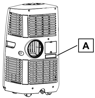
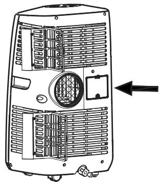
- Specifications for the power supply must correspond to the electrical data on the product ID plate A (fig.1)
ENGLISH
1
Tips for saving electricity.
- Do not use the appliance rooms that are bigger than the recommended volume (model 10 - 60 m 3 , model 12 - 72 m 3 ).
- Keeps doors and windows closed.
- Keep blinds and shutters closed when the sun is at its hottest.
- Make sure the filters are always clean (See Maintenance/Cleaning).
- When the required room temperature has been reached, turn the temperature and fan speed settings down.
Components
Front (fig.2)
2
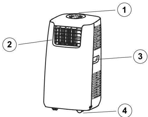
1 Control panel;
2 Cold air outlet grille;
3 Handle;
4 Wheels;
Rear (fig 3)
3
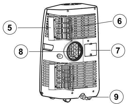
5 Air filter;
6 Air intake grille;
7 Cable housing;
8 Hot air outlet grille;
9 Condensation drainage hole with plug;
Accessories supplied (fig.4)
4
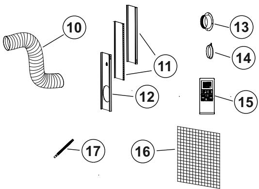
10 Hot air extraction hose
11 Window panel (to be fitted to the space left for the hot air extraction hose);
12 Window panel (to be fitted to the space left for the hot air extraction hose) with a hole for fitting the hose;
13 Rounded connector for the hose, to be fitted to the hole in the window or in the wall where the hot air is to be extracted from;
14 Blanking cap for connector mentioned in point 13;
15 Remote control unit;
16 Active carbon filter;
17 Condensation drainage hose;
ENGLISH
Installation
Installation of hot air extraction hose. Use the window panel (fig.5)
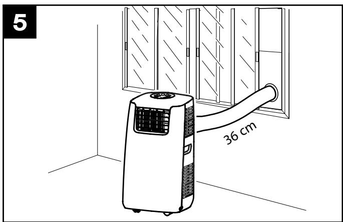
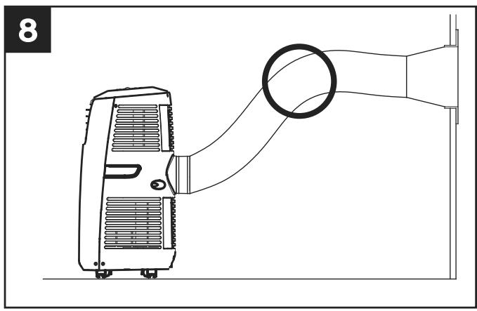
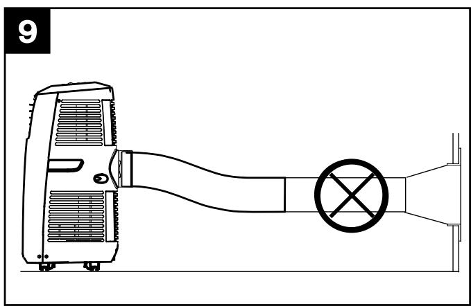
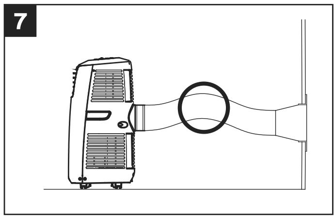
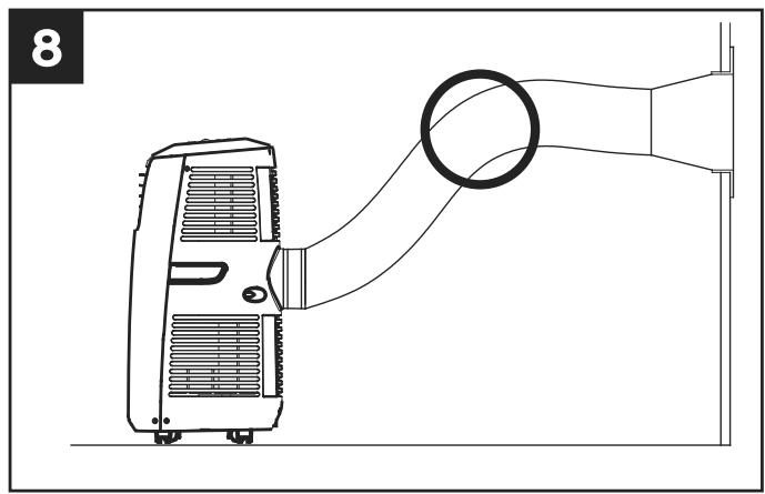
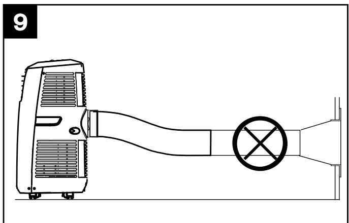
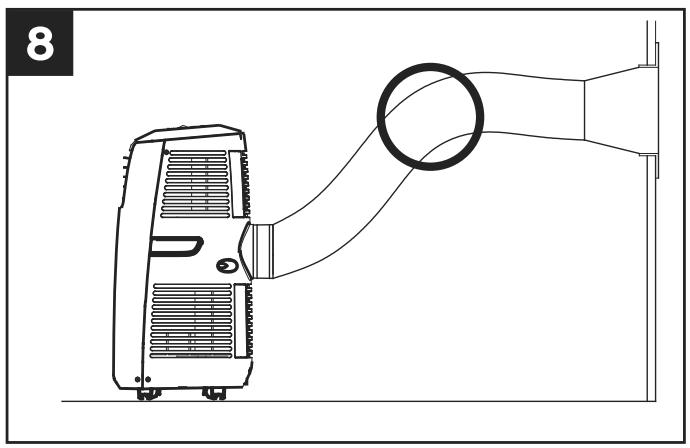
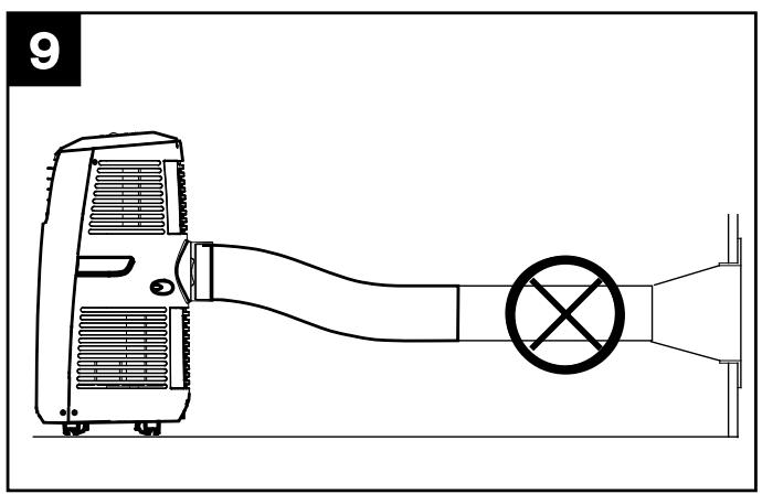
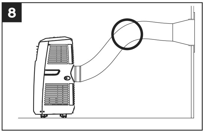
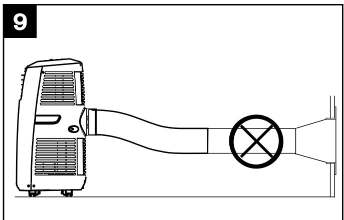
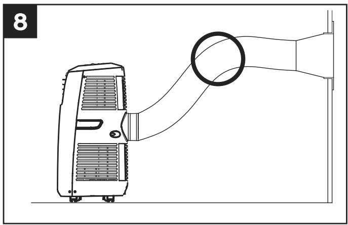
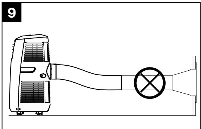
The hot air extraction hose supplied with the appliance can be extended by 300 to 1500 mm (figs 7,8); It is best to use the smallest possible extension (fig.9).
- Fit the rounded connector (13) to the end of the hose (10).
- Insert the end of the hose into the hole in the panel (12).
- If the panel is too big, cut it to fit the window.
- Extract the hot air through the window or wall (fig.6)
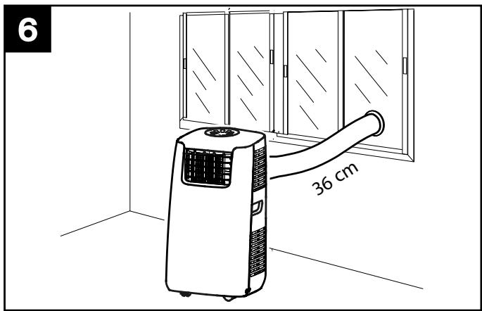
- Fit the rounded connector (13) to the end of the extraction hose.
- Make a hole (of more than 152 mm diameter) in the window or wall to accommodate the rounded connector.
When the appliance is disconnected from the window or wall, use the blanking cap (14) to cover the hole.
ENGLISH
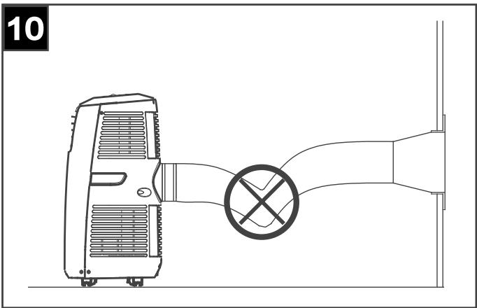
Take care not to form kinks in the hose (fig.10) where hot air could be trapped and then on escaping set off the automatic thermal cut-out system.
N.B.
The length of the hose has been carefully calculated to match the specifications of the appliance. You are advised not to replace the hose or extension as this may lead to a fault developing.
Fitting the active carbon filters
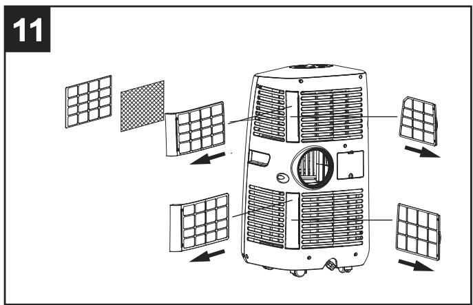
Remove the filter holder frame from the appliance (fig.11)
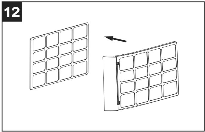
Remove the filter fastening device from the frame (fig.12)
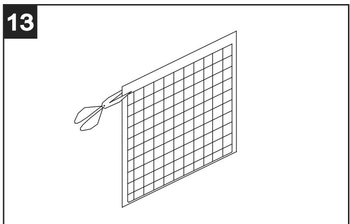
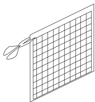
Remove the filter from its packaging (fig.13)
ENGLISH
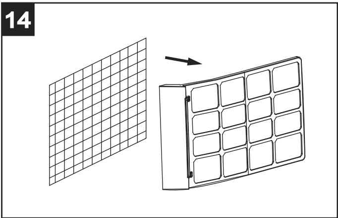
Insert the filter into the frame (fig.14)
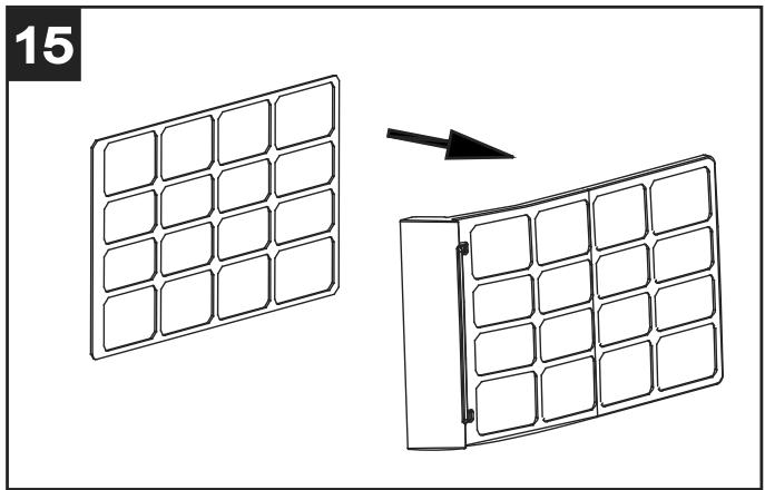
Fit the filter and reassemble the fastening device (fig.15)
Refit the filter holder to the appliance
Function
Control panel (fig.16)
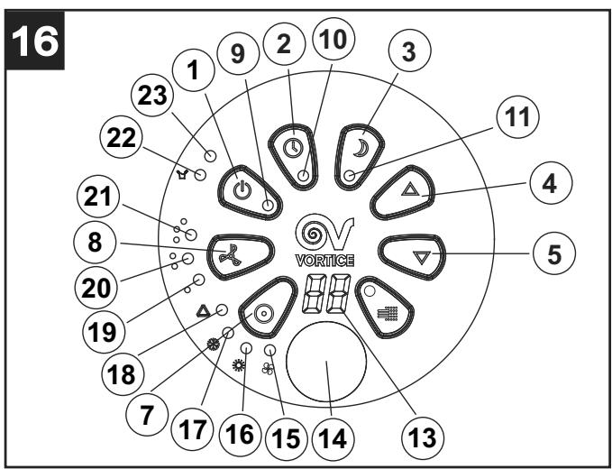
1 On/off
2 Timer
3 "Night time" function
4 Temperature "UP"
5 Temperature "DOWN"
7 Operation mode
8 Fan speeds
Indicators
9 Power Supply
10 Timer
11 "Night" function
13 Display
14 Slot for receiving signal from remote control unit
15 Fan mode
16 Dry mode
17 Cooling mode
18 Automatic mode
19 Minimum speed
20 Medium speed
21 High speed
22 Condensation tank full
23 Compressor on
Functions
Switching On/Off
Press ON/OFF: the appliance comes on in Cooling Mode at minimum speed; the preset temperature is 24° C
All the indicator lights come on at the same time; the display shows ambient temperature from 0° C to 50° C to turn the appliance off, press the ON/OFF button.
Setting operating mode
Press the MODE button to select the required operating mode: Fan, Dry, Cooling, Auto. The indicator light for the mode selected will come on.
If the room temperature drops below the set limit, the Cooling Mode automatically cuts out and the appliance continues to operate in Fan Mode at the preset speed. If room temperature rises to above the preset limit, the appliance automatically goes back to Cooling Mode.
Setting the temperature
Use the Temperature “UP” and Temperature “DOWN” buttons to set the required temperature.
While the temperature is being set, the display shows the reading. When a temperature has been set, the display will return to showing room temperature.
The appliance preset temperature is 24° C
Setting fan speed
Press SPEED to select the required fan speed setting: Minimum, Medium, Maximum. The indicator light for the mode selected will come on at the same time.
ENGLISH
Setting the timer
Press TIMER to set the required operating time (from 1 to 24 hours): the Timer light will come on and the display will show how long the appliance is set to run for. After this period, the appliance will switch itself off automatically.
By pressing the button when the appliance is switched off, the appliance can be set to start at a later time. (e.g. pressing 2 means the appliance will start working 2 hours later)
Setting Night mode
If you press SLEEP while the appliance is in Cooling Mode, the preset temperature will increase by 1° C after one hour and by a further 1° C after the second hour.
In “Night” mode, fan speed is automatically set to its lowest level. Pressing SLEEP again, the temperature and fan speed return to their preset levels.
N.B.
The appliance switches itself off automatically after operating for 12 hours of continuous running in Night mode.
N.B.
Night mode can only be activated if the appliance is in Cooling mode i.e. it is not an option in Fan or Dry operating mode.
Auto-diagnosis
The appliance can carry out auto-diagnosis. In the event of a malfunction, the display on the control panel will show “E1” or “E2”. In such event, contact an authorised Vortice Service Centre.
N.B.
All the functions mentioned above can be activated from the remote control unit provided (fig.17).
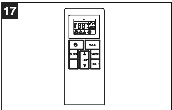
Use 3 Volt (CR2025) lithium batteries in the remote control unit.
"Super Cool" mode
To ensure that the appliance works properly in
"Super Cool" mode, make sure that the tank is filled.
The procedure is as follows:
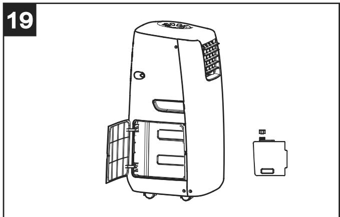
- remove the tank, open the lid with the handle (fig.19) and fill it with water;
19
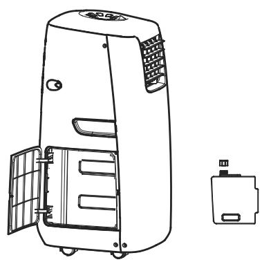
- replace the tank.
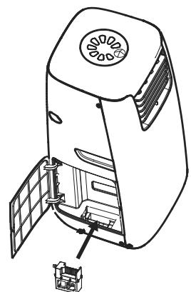
The filter can be removed and cleaned (fig. 20).
20
ENGLISH
Removing condensation
When the appliance is operating in Cooling or Dry mode, humidity extracted from the air is collected in an internal tank. If the tank reaches full, the compressor and motor cut out automatically. At the same time, the “condensation tank full” light comes on. An alarm will also sound. When the tank is full, carry out the following instructions: (fig.21)
21
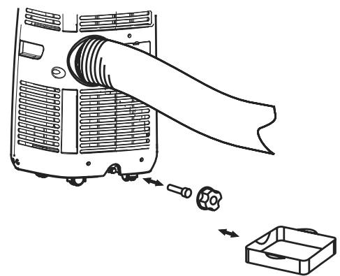
1 Turn the appliance off taking care not to move it so as to prevent spilling water from the tank.
2 Place a basin under the appliance drain hole.
3 Remove the drain handle and the rubber cap to let the condensation flow out.
4 When the basin is nearly full, replace the rubber cap and empty the basin.
5 Repeat as above until the condensation tank is empty.
6 Replace the rubber cap and handle.
7 Turn the appliance on again. The “condensation tank full” light should now be off.
Should you prefer to use the appliance without having to empty the tank every so often, proceed as follows: (fig.22)
22
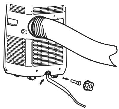
1 Remove the drain handle and the rubber cap and set them aside for future use.
2 Connect one end of the continuous condensation drainage hose (supplied) to the appliance drain hole and place the other end in a drain.
3 The hose can be connected to an extension hose that has an external diameter of 18mm.
N.B.
Needless to say, the drain must be at a lower level than the drain hole on the appliance. Should you opt for continuous drainage, the “condensation tank full” light is deactivated.
Maintenance/Cleaning
Cleaning the appliance body
N.B.
Before starting any cleaning work, remove the plug from the main socket.
Clean the appliance with a damp cloth, warm water (no hotter than 40° C) and a neutral detergent. Do not use aggressive solvents or detergents.
Cleaning the filters
Use a vacuum cleaner or delicately shake the filters to remove any dust. Next rinse the filters under running water (no hotter than 40° C) and allow them to dry before refitting.
N.B.
Never turn the appliance on without the filters.
End of season servicing
Remove the plug and rewind the cable (fig.23).
23
Completely empty the condensation tank.
Clean the filters.
On a warm day, turn the appliance on for several hours in Fan mode to thoroughly dry the inside of the unit.
You are advised to use the original packaging materials and not to place heavy items on top of the appliance.
ENGLISH
Trouble-shooting
In the event of malfunction, before contacting an authorised Vortice Service Centre, you are advised to carry out the following checks:
The appliance is not working
Is it plugged in?
Is there a power failure?
Are the compressor or “condensation tank full” lights flashing?
Is room temperature lower than the set level?
The appliance is not performing well
Is sunlight entering and heating the room? (If so, close the curtains, if present)
Are there doors or windows open?
Is the room over-crowded?
Is there a source of heat in the room?
The appliance works but seems to have no effect
Is the filter dirty or blocked?
Are the inlet and/or outlet grilles obstructed?
Is room temperature lower than the preset level?
The appliance is very noisy
Is the appliance sitting on the level or in an unusual position that may give rise to vibration?
Is the floor level?
The compressor is not working
The compressor thermal cut-out may have been activated due to excessive room temperature. Wait for a few minutes then try to restart the appliance
N.B.
Never attempt to repair or dismantle the appliance, Always contact an authorised Vortice Service Centre.
IN CERTAIN EUROPEAN UNION COUNTRIES THIS PRODUCT DOES NOT FALL WITHIN THE REQUIREMENTS OF THE NATIONAL LAWS IMPLEMENTING DIRECTIVE RAEE, AND IN THESE COUNTRIES THE PRODUCT IS NOT SUBJECT TO SEPARATE DISPOSAL OPERATIONS AT THE END OF ITS WORKING LIFE.
This product complies to European Directive 2002/96/EC.
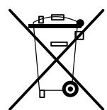
At the end of its useful life, the product marked with the crossed out wheeled bin must be disposed of separately from urban waste. It must be taken to a differentiated disposal centre for electrical and electronic appliances or be returned to the retailer when a new equivalent appliance is bought.
Subject to current legislation on waste disposal, the user is legally responsible for taking the appliance at the end of its useful life to a suitable disposal centre.
Appropriate differentiated waste collection for subsequent recycling, treatment and environment-friendly disposal of the discarded equipment helps to prevent possible negative environmental and health effects and encourages recycling of the component materials of the equipment.
For further information about available waste disposal systems, contact your local waste disposal service or the shop where you bought the product.
The manufacturers and importers comply with their responsibility for recycling, treating, and environmentally compatible disposal of waste both directly and collectively.
FRANÇAIS
FRANÇAIS
N.B :
FRANÇAIS
FRANÇAIS
Élimination condensation
1 Bedienblende
DEUTSCH
Achtung:
DEUTSCH
DEUTSCH
DEUTSCH
ESPAÑOL
NOTA:
Extraer el filtro del envase (fig.13)
13
ESPAÑOL
ESPAÑOL