
EFC 4 A - Electric control system ULTRAFLEX - Free user manual and instructions
Find the device manual for free EFC 4 A ULTRAFLEX in PDF.
| Product type | Smoke extraction control panel |
| Brand | ULTRAFLEX |
| Model | EFC 4 A |
| Dimensions (WxHxD) | 196 × 246 × 98 mm |
| Supply voltage | 230 Vac or 115 Vac depending on version |
| Rated current | 4 A |
| Actuator output voltage | 24 Vdc with polarity reversal |
| Number of motor outputs | 2, max load 2 A each |
| Siren/relay output | 1 output for self-powered siren |
| Smoke detector inputs | 1 input |
| Manual control inputs | 2 inputs for buttons |
| Emergency control box input | 1 input |
| Batteries | 2 × 12 V, 4 Ah (lead) |
| Battery charging time | Max 10 hours |
| Visual indicators | Green (mains), yellow (fault), red (alarm) LEDs |
| Acoustic signals | Output for external self-powered siren |
| Main functions | Emergency opening/closing via smoke detectors or emergency box; manual control for ventilation |
| Maintenance | Semi-annual functional check; replace batteries every 3 years |
| Safety | Disconnect power and batteries before intervention; installation by qualified personnel; omnipolar circuit breaker required |
| Spare parts | UCS battery set art. 40911V |
| Warranty | 2 years from date of manufacture |
Frequently Asked Questions - EFC 4 A ULTRAFLEX
User questions about EFC 4 A ULTRAFLEX
0 question about this device. Answer the ones you know or ask your own.
Ask a new question about this device
Download the instructions for your Electric control system in PDF format for free! Find your manual EFC 4 A - ULTRAFLEX and take your electronic device back in hand. On this page are published all the documents necessary for the use of your device. EFC 4 A by ULTRAFLEX.
USER MANUAL EFC 4 A ULTRAFLEX
USER'S MANUAL: INSTRUCTIONS AND WARNINGS
C E
Smoke vent control panel “EFC 4 A”
Versions 230 VAC-24 VDC and 115 VAC-24VDC

The smoke vent control panel EFC 4 A allows to control the windows opening or closing by 24 VDC actuators using an opening/closing operation with polarity inversion.
Opening and closing operation can be controlled as follows:
- For emergency by smoke detectors (Part No. 36418Q) or an emergency pushbutton (Part No 40564B)
- For ventilation by a standard button (Part No 40050U or similar).
The emergency push-button Part No 40564B is recommended to signal the EFC control panel conditions when the panel itself is installed in a not visible position.
Obviously the emergency command has priority over ventilation (manual opening and closing are disabled).
The actuators are fed directly by a power supply unit; the batteries are used in case of voltage supply failure only.

WARNING:
- read the instruction manual carefully before assembling
- keep this manual also after installation for any further issue
- uncorrect or improper installation may cause failure of the system and/or injury to things or people
- electrical connections must be carried out by qualified people only
- turn the power off before opening the control unit
TECHNICAL DATA
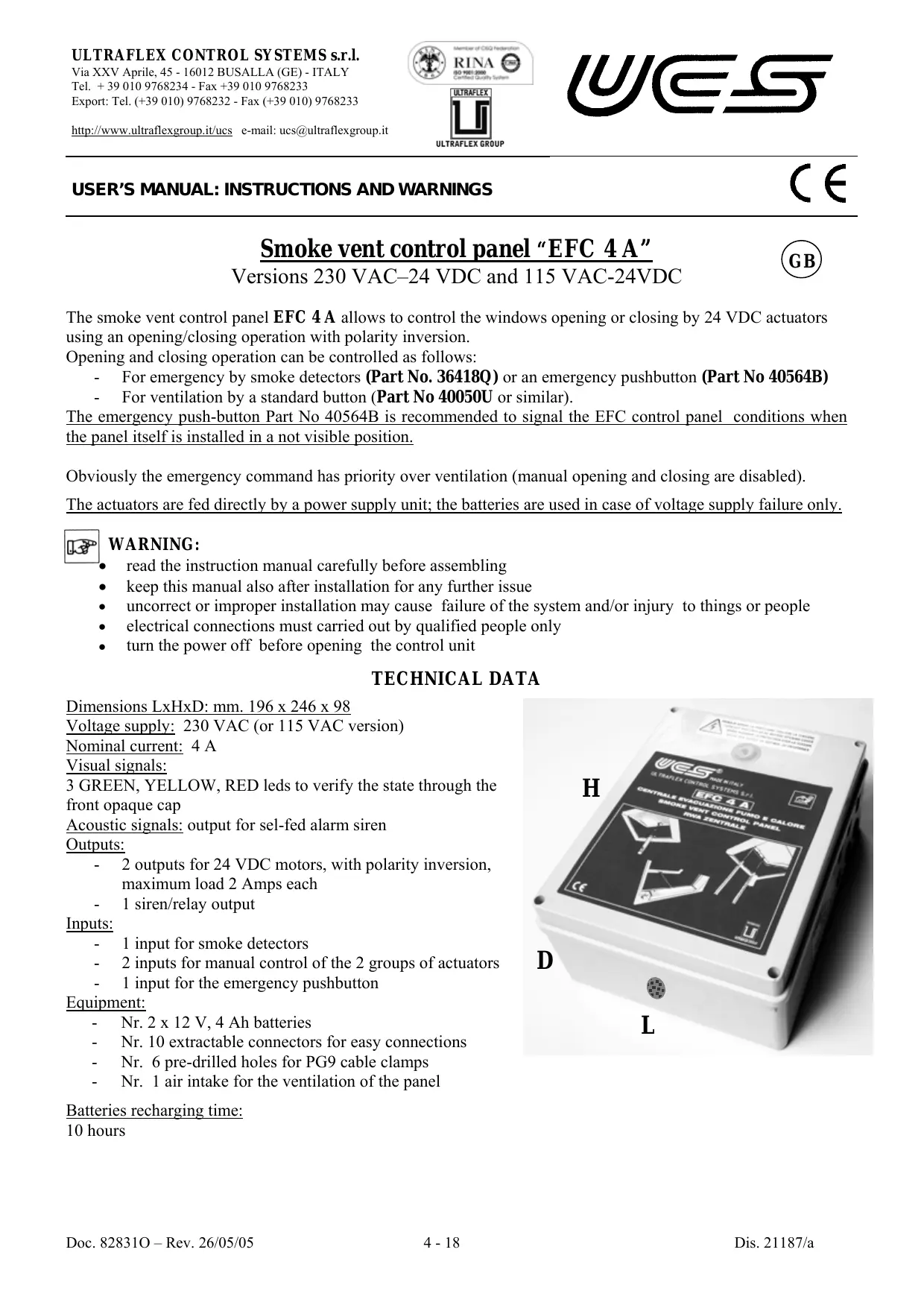
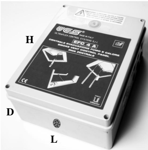
Dimensions LxHxD: mm. 196 x 246 x 98
Voltage supply: 230 VAC (or 115 VAC version)
Nominal current: 4 A
Visual signals:
3 GREEN, YELLOW, RED leads to verify the state through the front opaque cap
Acoustic signals: output for Sel-fed alarm siren
Outputs:
- 2 outputs for 24 VDC motors, with polarity inversion, maximum load 2 Amps each
- 1 siren/relay output
Inputs:
- 1 input for smoke detectors
- 2 inputs for manual control of the 2 groups of actuators
- 1 input for the emergency pushbutton
Equipment:
- Nr. 2 x 12 V, 4 Ah batteries
- Nr. 10 extractable connectors for easy connections
- Nr. 6 pre-drilled holes for PG9 cable clamps
- Nr. 1 air intake for the ventilation of the panel
Batteries recharging time:
10 hours
OPERATION
EMERGENCY
1. Signal from smoke detector part No. 36418Q
This emergency is relevant to the presence of smoke.
The smoke detector memorizes any active alarm until it is disconnected from its base or the reset button is pressed on the emergency push-button (if present) or the reset inside the control unit.
This alarm state sends the opening command, the red led of the emergency push button (if present) and of the control unit switches on, and the siren output is activated for as long as the alarm state remains active.
2. Pressing emergency button (N.C. button) part No. 40564B
To activate the emergency opening control, press the button on the emergency push-button; the red led of the emergency push-button and of the control unit switches on, and the siren output is activated as long as the alarm state remains active. The state of emergency can be deactivated any time by pressing the reset button on the push-button or inside the control unit.
The presence of the emergency push-button is recommended to activate manually the emergency opening control and to display the anomaly/emergency and RESET signals.

N.B.: in case of alarm all manual controls is disabled.
MANUAL CONTROLS
For the manual control, 2 inputs are provided for standard buttons (part No. 40050U or others), each of which controls an actuator output.
The control unit receives the impulse command and maintains it for 3 minutes to allow every actuator to reach the limit stop.
The control can be stopped using the following ways:
a) after reaching the maximum travel time of 3 minutes
b) pressing the reset key (the device stops)
c) pressing and quickly releasing the relevant control key (the device stops)
When the actuator is stopped, to select the new direction of travel, press and release the button relevant to the new action desired.

N.B.:
- in case of alarm, all the manual controls are disabled.
- in case of voltage supply failure, only 1 closing control will be allowed (to avoid the consumption of the batteries and to close the windows waiting for the main power to return).
ANOMALIES
Anomalies are signalled on the control unit (through the transparent cap) and on the emergency push-button (here the led blinks) by the lighting of a yellow led.
Anomalies can be the followings:
- interruption of the smoke detectors electric wire
- interruption and short-circuit of the actuators electric wire
- flat or low batteries (every 6 hours an automatic check up is provided)
SIGNALS
Visual signals are provided through led inside the control unit and on the emergency push-button, as well as emergency acoustic signals through the self-fed external siren (part No. 40892C or similar) connected to the SIREN/RELAY output. The leads inside the control unit are evident through the transparent cap on the cover.
Green led on: it indicates the voltage supply is on
Yellow led on (blinking on the pushbutton panel): it indicates one of the above anomalies is present
Red led on: it indicates an alarm is active

In a normal operating condition, if voltage supply is provided and no alarms or anomalies are present, only the green led should be lit.
Siren: the self-fed siren, connected to the SIREN/RELAY output, is activated by the presence of an alarm.
BATTERIES
The control unit is supplied with a set of 2 × 12V - 4Ah lead batteries, charged, but with the black negative (-) wire disconnected and insulated to prevent their discharging when not charged by the voltage supply.
Batteries are used in case of voltage supply failure only and guarantee the emergency opening of the windows also after a long blackout.
The state of the batteries is controlled every 6 hours.

We recommend to change the batteries every 3 years with equivalent ones (available in set UCS part No. 40911V).

BATTERIES MUST BE REMOVED FROM THE DEVICE BEFORE ITS DISPOSAL, AND ELIMINATED IN A CORRECT WAY.

IMPORTANT NOTE FOR INSTALLATION
See the drawing "ELECTRICAL
CONNECTIONS" below, and/or the plate inside the cover of the control unit.
The control unit is supplied with all the electric connections (electronic board/transformer/batteries) already made, apart from the black negative (-) wire of the battery:
Connect the above wire to the corresponding free pole on the battery ONLY AFTER THE OTHER WIRING.
The control unit is supplied with some resistors/capacitors mounted on connectors to be able to switch it on without any device connected and without activating any alarm.
When the various accessories (smoke detectors, push-button, actuators) are connected, these resistors/capacitors must be moved as shown in the drawing "ELECTRICAL CONNECTIONS":
- the 4.7 KΩ resistor on terminal J8 must be moved to the end of the smoke detectors line;
- the 100KΩ resistor on terminal J9 (5-6) must be replaced by the connections of the emergency push-button (verify that the resistor on terminals 7-11 of the push-button panel is already present);
- the 1µF capacitors on J10 and J11 must be moved to the actuators line, before the last two ones, to check for any cut wires.

N.B.: if actuators "RACK 24V" and "SUPERMASTER 24V" are installed, no capacitor application is required.
Use connector J4 and the screw with the earth symbol for the connection to the voltage supply.
MAINTENANCE
- We recommend checking the control unit is working properly at least once every 6 months. The control unit has to be tested by commanding a complete opening and closing for ventilation (after which none of the yellow Leds inside the control unit or on the emergency push-button should be lit) and by activating an emergency command by pressing the emergency button or simulating a smoke alarm.
We recommend to change the batteries every 3 years with equivalent batteries (UCS set available, part No. 40911V).

SAFETYWARNINGS
- The electrical system has to comply the current specifications
- Before any action inside the control unit makesure the voltage supply and the batteries are disconnected.
- The voltage supply network must provide an omnipolar disconnecting device (in accordance with CEI EN 60335-1).
- Any installation and/or maintenance must be carried out by qualified personnel.
- Respect the wiring diagram indicated in the drawing "ELECTRICAL CONNECTIONS" or in the plate inside the cover of the control unit.
GUARANTEE
Ultraflex Control Systems S.r.l. products are guaranteed, for a period of two years from the manufacture date, against defects in material and workmanship.
Alleged defective products returned, freight prepaid, within the above said term, will be repaired or replaced free of charge, at our option, if found effectively below our quality standards.
This guarantee does not cover other claims for direct or indirect damages.
In particular, we decline liability and exclude guarantee (except for what stated above) if improper installation or misuse should result in a failure of our products.
MANUEL D'UTILISATION: INSTRUCTIONS ET AVERTISSEMENTS
C E
CONDITIONS DE GARANTIE
INSTALLATIONSHANDBUCH:
Con el actuador parado, para selectionar el nuevo sentido de marcha deseado es suficiente pulsar y soltar el botón relativo a lareshareshareshareshareshareshareshareshareshareshareshareshareshareshareshareshareshareshareshareshareshareshareshareshareshareshareshareshareshareshareshareshareshareshareshareshareshareshareshareshareshareshareshareshareshareshareshareshareshareshareshal

NOTA:
N.B.: if actuators "RACK 24V" and "SUPERMASTER 24V" are installed, no capacitor "5" application is required.
- USER'S MANUAL: INSTRUCTIONS AND WARNINGS
- C E
- SMOKE VENT CONTROL PANEL “EFC 4 A
- VERSIONS 230 VAC-24 VDC AND 115 VAC-24VDC
- WARNING
- TECHNICAL DATA
- OPERATION
- EMERGENCY
- SIGNAL FROM SMOKE DETECTOR PART NO. 36418Q
- PRESSING EMERGENCY BUTTON (N.C. BUTTON) PART NO. 40564B
- MANUAL CONTROLS
- N.B
- ANOMALIES
- SIGNALS
- BATTERIES
- IMPORTANT NOTE FOR INSTALLATION
- CONNECT THE ABOVE WIRE TO THE CORRESPONDING FREE POLE ON THE BATTERY ONLY AFTER THE OTHER WIRING
- MAINTENANCE
- SAFETYWARNINGS
- GUARANTEE
- MANUEL D'UTILISATION: INSTRUCTIONS ET AVERTISSEMENTS
- CONDITIONS DE GARANTIE
- INSTALLATIONSHANDBUCH
- NOTA
Brand : ULTRAFLEX
Model : EFC 4 A
Category : Electric control system