
CALYPSO SPLIT INVERTER - Water heater ATLANTIC - Free user manual and instructions
Find the device manual for free CALYPSO SPLIT INVERTER ATLANTIC in PDF.
User questions about CALYPSO SPLIT INVERTER ATLANTIC
0 question about this device. Answer the ones you know or ask your own.
Ask a new question about this device
Download the instructions for your Water heater in PDF format for free! Find your manual CALYPSO SPLIT INVERTER - ATLANTIC and take your electronic device back in hand. On this page are published all the documents necessary for the use of your device. CALYPSO SPLIT INVERTER by ATLANTIC.
USER MANUAL CALYPSO SPLIT INVERTER ATLANTIC
Electric water heater
Raccordement hydraulique 12
Raccordement electrique 14
2. Raccordement hydraulique
- This device is not intended for use by persons (including children) with physical, sensory or mental disability, or by persons lacking experience or knowledge, unless they have received from a person in charge of their safety adequate supervision or preliminary instructions on how to use the device.
- Children should be supervised to ensure that they do not play with the appliance.
- This unit can be used by children of not less than 8 years and people with reduced physical, sensory or mental capabilities or without experience or knowledge it the are properly supervised or if the instructions for using the device safely have been given and if the risks are tacking into account. Children must not play with the device. Cleaning and maintenance must not be done by children without supervision.
INSTALLATION :
Caution : Heavy items - handle with care
- Install the appliance in a room which is protected from frost. If the appliance is damaged because the safety device has been tampered with, it is not covered by the guarantee.
- Make sure that the wall on which the appliance is mounted can support the weight of the appliance when filled with water.
- If the appliance is to be fitted in a room or location where the ambient temperature is higher than 35^ , ventilation must be provided in the room.
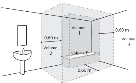
- When installed in a bathroom, do not install the appliance in volumes V0 and V1 (see fig). If the available space is too small, they can nevertheless be installed in the volume V2 or the highest position possible in volume V1 for a horizontal model.
- Position the appliance where it can be accessed.
- Refer to the installation figures of the "Installation" chapter.
Fixation of a vertical wall mounted water heater: To allow the possible exchange of the heating element keep, below the ends of the tubes of the boiler, a free space of 480mm .
WATER CONNECTIONS
A new safety device which conforms to current standards (in Europe EN 1487), pressure 7 bar - 0,7 MPa - and size 3/4'' (1/2" for 500 L) in diameter must be fitted. The safety valve must be protected from frost.
Connect the safety device to an unpressurised outlet pipe in a frost free environment, with a continuous slope for the evacuation of the water during heating up or draining the water heater.
A discharge pipe connected to the safety unit must be installed in a frost-free aera, on a continuous downward slope.
Operates once a month the discharge of water security to prevent scaling and verify that it is not blocked.
A pressure reducer (not supplied) is required when the water supply pressure exceeds 5 bar - 0,5 MPa.
Connect the safety device to an unpressurised outlet pipe in a frost free environment, with a continuous slope for the evacuation of the water during heating up or draining the water heater.
DRAIN: Turn off the power and the supply of cold water, open the hot water faucets and manipulate the safety valve before performing these operations.
ELECTRICAL CONNECTIONS
Before removing the cover, switch off the power.
The installation must be equipped, upstream of the appliance, with a bipolar cut-out device ( fuse, breaker switch.) (30 mA earth-leakage breaker)
If the power cable is damaged, it must be replaced by the manufacturer, the after-sales service or similarly qualified persons in order to avoid any danger.
Installation and maintenance
Water Heater
Table of Contents
Installation
Description of the equipment. 33
Characteristics 33
Compatible accessories 37
Installation 40
Installing the water heater 40
Connecting the water 41
Electrical connections 43
Commissioning the water heater 46
Filling the water heater 46
Checking that the appliance works. 46
GIFAM recommendations 47
Mechanical risks 47
Electrical risks 47
Hydraulic risks 47
Maintenance
Description of the water heater 48
the water heater 48
Maintenance 49
Safety information 49
Water heater maintenance 49
Troubleshooting 54
Guarantee - Customer Service - Compliance 56
Conditions of guarantee 56
Scope of the guarantee 56
After-sales department 57
GIFAM recommendations 58
Description of the equipment
1. Characteristics
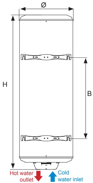
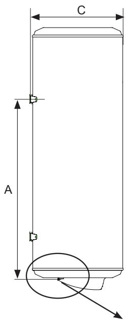
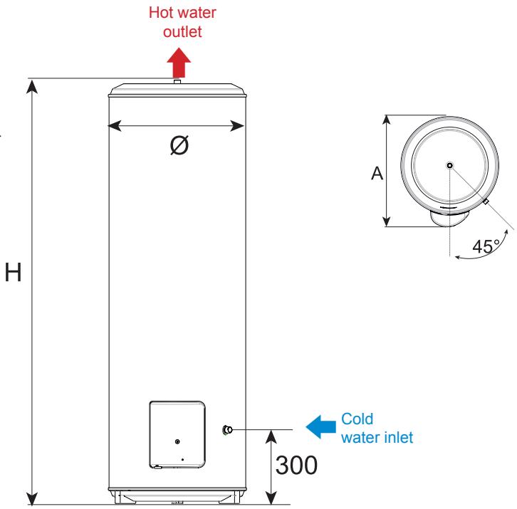
1.1 Vertical wall-mounted water heater (VM)
| 50 litres | 75 litres | 100 litres | 150 litres | 200 litres | ||
| Voltage (V) | 230 V~ monophase no kit available | 230 V~ monophase (can be converted into 400 V three-phase with the kit) | ||||
| Resistor | steatite | |||||
| Power (W) | 1 200 | 1 200 | 1 200 | 1 800 | 2 200 | |
| Dimensions (mm) | ∅ | 505 | 510 | 510 | 530 | 530 |
| H | 575 | 735 | 900 | 1200 | 1515 | |
| A | 370 | 575 | 750 | 1050 | 1050 | |
| B | / | / | / | 800 | 800 | |
| C | 530 | 530 | 530 | 550 | 550 | |
| Heating time* | 2h30 | 4h05 | 5h28 | 5h25 | 5h45 | |
| Qpr (Maintenance consumption)** | 0,82 | 1,08 | 1,30 | 1,50 | 1,79 | |
| V40 (Quantity of hot water at 40°C, (litres)) | / | 137 | 187 | 295 | 381 | |
| Empty weight (kg) | 23 | 27 | 30 | 39 | 49 | |
| 50 litres | 75 litres | 100 litres | 150 litres | 200 litres | ||
| Voltage (V) | Accelerated 230V single-phase (can be converted into 400 V three-phase or 230V three-phase with the appropriate kit) | |||||
| Resistor | Steatite | |||||
| Puissance (W) | 1800 | 3000 | 3000 | 3000 | 3000 | |
| Dimensions (mm) | ∅ | 505 | 510 | 510 | 530 | 530 |
| H | 575 | 735 | 900 | 1200 | 1515 | |
| A | 370 | 575 | 750 | 1050 | 1050 | |
| B | / | / | / | 800 | 800 | |
| C | 530 | 530 | 530 | 550 | 550 | |
| Heating time* | 1h30 | 1h30 | 2h04 | 3h11 | 4h15 | |
| Qpr (Maintenance consumption)** | 0,82 | 1,08 | 1,30 | 1,50 | 1,79 | |
| V40 (Quantity of hot water at 40°C (litres)) | / | 137 | 187 | 295 | 381 | |
| Empty weight (kg) | 23 | 29 | 30 | 39 | 49 | |
| Compact 100 litres | Compact 150 litres | Compact 200 litres | ||
| Voltage (V) | 230 V~ mono- phase no kit available | 230 V~ monophase (can be converted into 400 V three-phase with the kit) | ||
| Resistor | steatite | |||
| Power (W) | 1 200 | 1 800 | 2 200 | |
| Dimensions (mm) | ∅ | 570 | 570 | 570 |
| H | 770 | 1 035 | 1 285 | |
| A | 600 | 760 | 1 040 | |
| B | / | 500 | 800 | |
| C | 590 | 590 | 590 | |
| Heating time* | 5h17 | 5h15 | 5h43 | |
| Qpr (Maintenance consumption)** | 1,024 | 1,37 | 1,67 | |
| V40 (Quantity of hot water at 40°C, (litres)) | 175 | 266 | 359 | |
| Empty weight (kg) | 31 | 41 | 50 | |
Heating time for heating between 15 and 65^ C
*Maintenance consumption in kWh for 24 hours for water at 65^ (ambient 20^ )
1.2 Vertical water heater on pedestal (VS)
| 150 litres | 200 litres | 250 litres | 300 litres | ||
| Voltage (V) | 230 V~ monophase (can be converted into 400 V three-phase or 230V three-phase with the appropriate kit) | ||||
| Resistor | Steatite | ||||
| Power (W) | 1 800 | 2 200 | 3 000 | 3 000 | |
| Dimensions (mm) | ∅ | 530 | 530 | 530 | 570 |
| H | 1 170 | 1 480 | 1 800 | 1 755 | |
| A | 600 | 600 | 600 | 640 | |
| Heating time* | 4h48 | 5h05 | 5h01 | 6h14 | |
| Qpr (Maintenance consumption)** | 1,56 | 1,92 | 2,15 | 2,41 | |
| V40 (Quantity of hot water at 40°C (litres)) | 274 | 365 | 471 | 559 | |
| Empty weight (kg) | 40 | 49 | 63 | 73 | |
*Heating time for heating between 15 and 65^
**Maintenance consumption in kWh for 24 hours for water at 65^ (ambient 20^ )
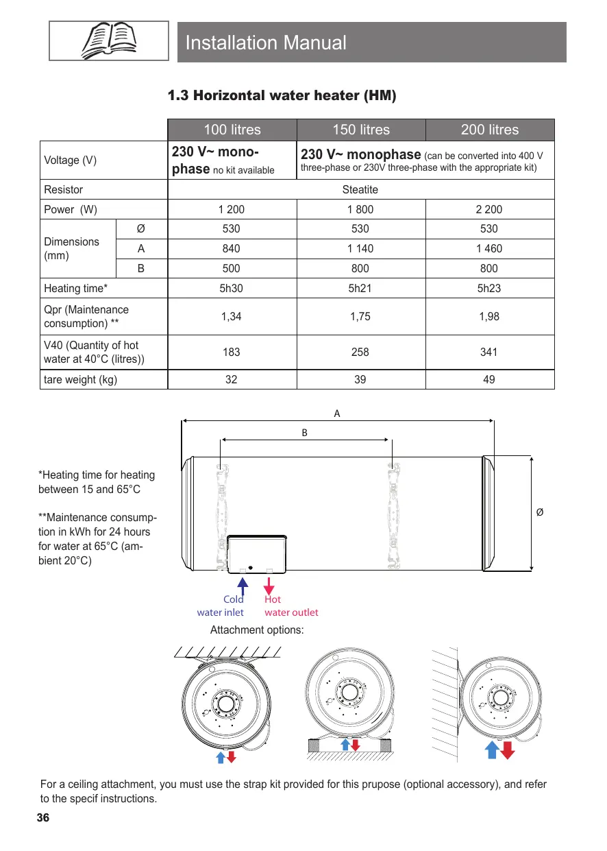
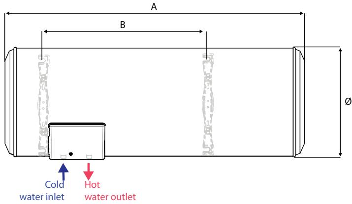
1.3 Horizontal water heater (HM)
| 100 litres | 150 litres | 200 litres | ||
| Voltage (V) | 230 V~ mono-phase no kit available | 230 V~ monophase (can be converted into 400 V three-phase or 230V three-phase with the appropriate kit) | ||
| Resistor | Steatite | |||
| Power (W) | 1 200 | 1 800 | 2 200 | |
| Dimensions (mm) | Ø | 530 | 530 | 530 |
| A | 840 | 1 140 | 1 460 | |
| B | 500 | 800 | 800 | |
| Heating time* | 5h30 | 5h21 | 5h23 | |
| Qpr (Maintenance consumption)** | 1,34 | 1,75 | 1,98 | |
| V40 (Quantity of hot water at 40°C (litres)) | 183 | 258 | 341 | |
| tare weight (kg) | 32 | 39 | 49 | |
*Heating time for heating between 15 and 65^ C
**Maintenance consumption in kWh for 24 hours for water at 65^ (ambient 20^ )
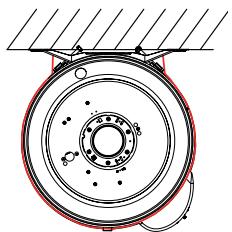
Attachment options:
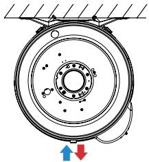
For a ceiling attachment, you must use the strap kit provided for this prposure (optional accessory), and refer to the specif instructions.
2. Compatible accessories
Dielectric fitting 20/27

Universal pedestal
Kit for 400 V three-phase transition
- To change a water heater from 230V single-phase to 400V three-phrase.

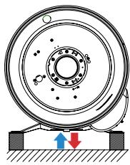
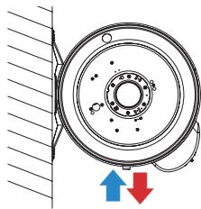
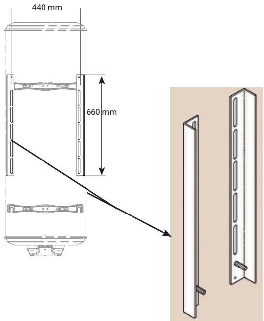
Quick mounting plate for vertical wall-mounted models
- The ideal solution for tight spaces: the appliance is hooked onto this support.
- Quicker installation time.
- Appliance can be easily fixed in angles or where there is no access to tighten it to the wall.
- Meets load bearing standards.
| Capacity | many plates |
| 50 to 100 litres | 1 |
| 150 to 200 litres | 2 |
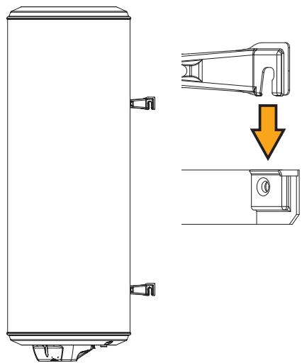
Universal mounting bracket for vertical wall-mounted model
- The ideal solution to reuse all types of old water heater fittings without making extra holes.
- Quicker installation time.
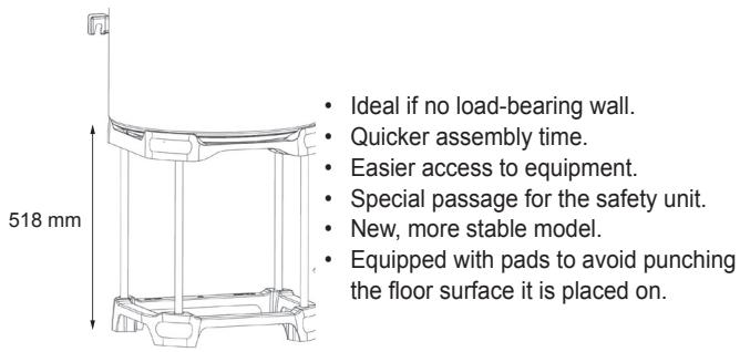
Ceiling mounting kit for vertical wall-mounted model
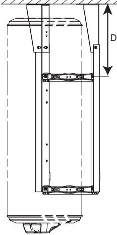
Useful when the wall cannot support the weight of the appliance.
- Frees space under the water heater.
- Robust as tested with overload (+50kg)
Distance D = 197 mm minimum for 75 to 200 l
Distance D = 225mm for 50 I
Strap kit
Spacer for 150l to 300l vertical model on pedestal
- The ideal solution when you need clearance under the unit.
Facilitates the implementation of piping.
Installation
1. Installing the water heater
- Put the water heater where it is protected from frost (4 to 5^ minimum).
- Position it as close as possible to the most frequently used taps.
- If it is installed in an uninhabited room (store-room, cellar, garage) the pipes and safety devices should be insulated.
- The continuous ambient temperature around the water heater must not exceed 40^ , so provide ventilation if necessary.
- Make sure that the wall-bracket is strong enough to carry the weight of the water heater when full of water.
- Allow 550~mm in front of each electrical element for periodic maintenance of the heating element.
- A drip tray must be installed under the water heater if it is positioned in a false ceiling, an attic or above living areas. An outlet connected to a drainpipe is necessary.
- Ventilation must be provided in damp locations.
1.1 Installing a vertical wall-mounted water heater (VM)
The heater is easily moved by lifting handles built into the ends. There are several ways of fixing it, depending on the nature of the walls.
Thin walls (plasterboard partitions):
10 ~mm threaded rods traversing the wall, connected by profiles or backplates.
Hard, thick walls (concrete, stone or brick):
Grout in 0 10 mm bolts, or drill to take 0 10 mm plugs.
For both types of walls, use the drilling template printed on the carton and check the measurements before drilling.
Walls not able to bear significant weight
The vertical wall-mounted water heaters can be placed on a pedestal if the wall cannot support the weight of the appliance. The top bracket must however be fixed. Use the pedestal recommended by the manufacturer.
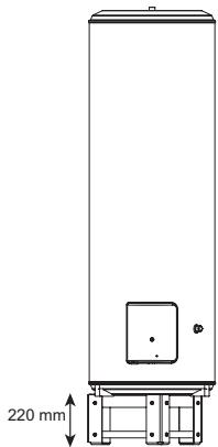
1.2 Installing a vertical water heater on a pedestal (VS)
The heater is placed on the ground with shoes fixed under its base. No wall attachment is needed.
A heightening frame may be fixed under the heater to leave space for the pipes (H : 220 mm – optional accessory).
1.3 Installing a horizontal wall-mounted water heater (HM)
Once the water heater is installed, the hydraulic connections and the cover must always be vertical and below the appliance.
2. Connecting the water
The water heater must be connected to the water supply in accordance with standards and with the regulations in force in the country where it will be installed (for France, D.T.U. 60.1).
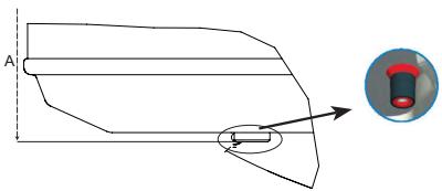
2.1 Identification of piping on the appliance
Each tube is a 20/27 (50 L to 300 L) steel pipe with gas pitch threaded end.
- The cold water inlet is marked by a blue collar, and the hot water outlet is marked by a red collar.
2.2 Connections to tubing
- The nature of the connecting tubes may be rigid, usually copper (black steel is prohibited) or flexible (standard flexible stainless steel braid).
- If copper piping is used, it must be connected to the hot water outlet using the supplied insulated fitting or a cast iron sleeve to prevent corrosion of the pipe (direct contact iron / copper). Brass fittings are prohibited at this level (NFC 15-100 for France).
- The connecting tubes must be sealed while installing the water heater (flax fibre, etc.), even if crosslinked PE pipes are used.
- A new safety device (not supplied) must be installed on the water heater input and must comply with the standards in force (in Europe: EN 1487), pressure 7 bar - 0.7 MPa - and size 3/4 (1" for the 500 l). Connect the safety unit to a drain pipe, kept in the open air, in a frost-free area and on a continuous downward slope to drain any expanded heated water or to drain the water heater.
- A discharge pipe connected to the safety unit must be installed in a frost-free area, on a continuous downward slope.
- If pipes made of synthetic material (such as PER) are used, a control thermostat must always be placed on the water heater outlet. It should be set appropriately for the material used.
- The pipes used must withstand 100^ and 10 bar - 1 MPa.
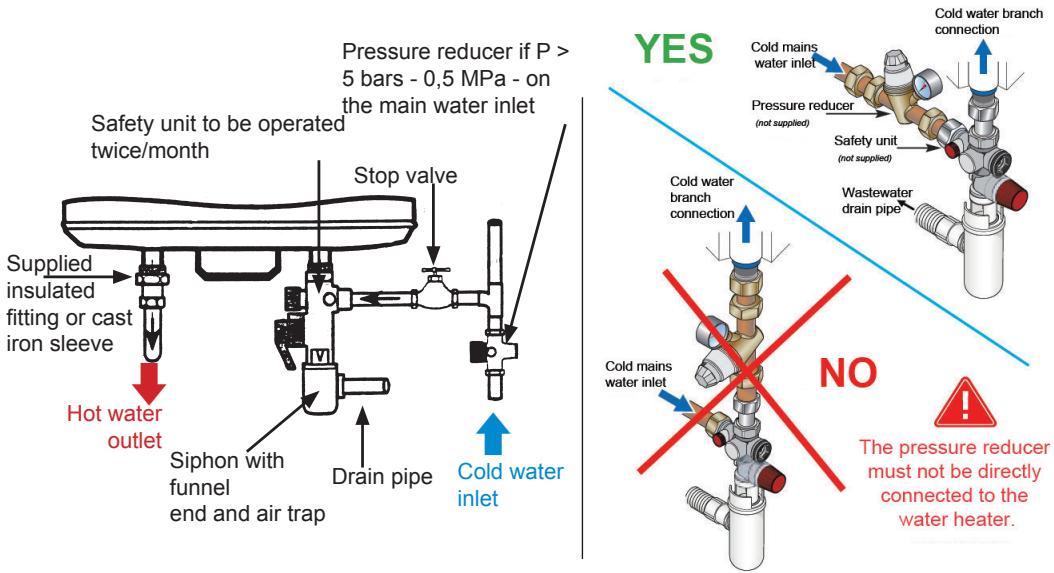
Connection diagram example of a vertical wall-mounted water heater

It is prohibited to attach a flexible hose between the water heater and the safety system.
The safety unit includes:
- 1 stop valve
1 manual drain valve - 1 non-return valve (to prevent water in the water heater from flowing back into the cold water network)
- 1 safety valve set to 7 bars - 0,7 Mpa
- 1 non-return valve inspection plug

The pressure in the cold water network it usually less than 5 bars - 0,5 MPa. If it is not, provide a pressure reducer that will be located on the water inlet after the meter.
2.3 Advice and recommendations
You are advised to install a temperature limiting device on the water heater output to reduce the risk of burns:
- In bathrooms and wash rooms, the maximum hot water temperature is 50^ at draw off points.
-
In other rooms, the maximum hot water temperature is 60^ at draw off points. In areas with very hard water (Th> 20^ ), you are advised to treat the water. With a water softener, the hardness of the water must remain above 15^ . The softener does not change our guarantee, provided it is CSTB-certified in France, is set appropriately and is regularly checked and maintained.
-
Decree No. 2001-1220 of 20 December 2001 and Circular DGS/SD 7A.
- Decree No. 2002-571 of 25 November 2002.
Compliance with DTU 60.1
3. Electrical connections
Our appliances comply with the standards in force and are therefore perfectly safe. The electrical connections must comply with installation standard NF C 15-100 and with the provisions in force in the country where the water heater will be installed (label, etc...).
The installation consists of:
- upstream from the water heater: A multi-pole circuit-breaker with contacts opening at least 3mm : fuse, circuit breaker).
-
A rigid mains cable of minimum section 3 × 2.5 ~mm^2 single-phase (phase, neutral, earth) or 4 × 2.5 ~mm^2 three-phase (3 phases + earth).
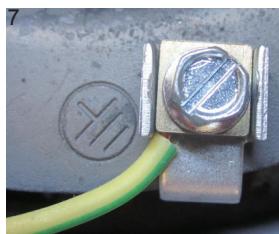
The earth conductor will be coloured green/yellow. -
Your water heater's electronic generator with an impressed-current anode system has been designed for a permanent power supply (24 hours a day), an 8 hours off-peak type, or an 8 hours off-speak type spread over two slots. Make sure that the installation complies with one of the two power supply options. The guarantee will not apply if the power supply time is less.
3.1 Recommendations
Cut the cable to an appropriate length to avoid contact with the heating elements. The earth connection is essential for safety raisons.

Direct connection to the elements (without passing through the thermostat) is strictly forbidden. It is dangerous because the temperature of the water is not controlled.
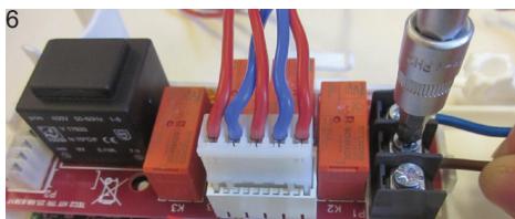
3.2 Connection procedure
Prior to electrical connection, make sure the power is off.
- Loosen the fixing screws and remove the protective cover which contains the electrical wiring diagram.
- The heater is delivered 230V ~ single-phase. For 400V ~ three-phase, replace the original single-phase plate with a 400V ~ three-phase kit. How to install this kit is explained further on in the manual.
- Feed the cable through the specific cable clamp
- Tighten the cable clamp.
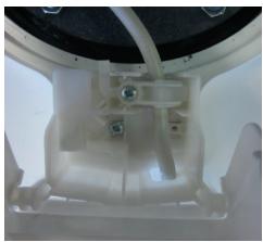
VM 501
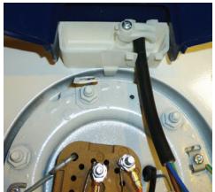
VM 75 to 200 I
VS
- Connect the ends of the cable to the thermostat's screw terminals provided for this purpose (you do not need to remove the thermostat).
- Connect the green/yellow earth wire to the terminal marked , on the water heater's flange
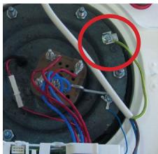
VM 501
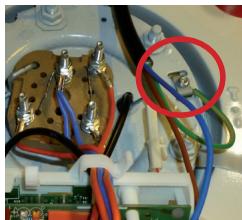
VM 75 to 200 I
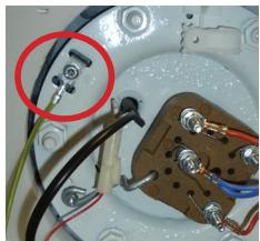
VS
- Refit the cover after checking the connection terminals are correctly tightened.
- Tighten the screws on the cover.
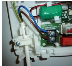
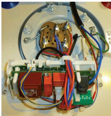
3.3 Instructions for changing to three-phase
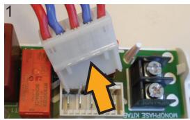
Disconnect the heating element's connector
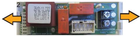
Unclip and remove the 230V board
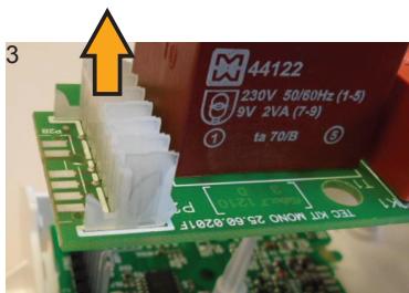
Disconnect the power board
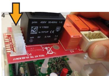
Reconnect the 400V power board
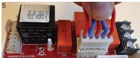
Put the heating element's connector back onto the 400 V power board
Connect the power cable, not forgetting the earth
3.4 Setting the temperature
The temperature is set to its max position in the factory. The temperature can be lowered by 15^ (1 degree per notch on the wheel).
Commissioning the water heater
1. Filling the water heater
- Open the hot water valve(s).
- Open the cold water valve on the safety unit (make sure that the heater drain valve is in the closed position).
- Once the water flows steadily from the hot water taps, close them. The water heater is full.
- Check that tubing connections are not leaking, and check the door seal under the electrical cover. Retighten it if necessary.
- Check that tubing connections are not leaking, and check the door seal under the electrical cover. Retighten it if necessary.
2. Checking that the appliance works
- Switch on the power.
-
If your electric board is fitted with a relay to take advantage of off-peak rates (reduced prices at night), set the switch to permanently on (I). You will see 3 positions in this switch.
-
Off or 0 position
Automatic or Auto position -
Forced operation or 1 position
-
The orange lamp lights up.
- After 15 to 30 minutes, water should start dripping through the safety unit drain outlet (which must be connected to a waste water drain pipe).
This phenomenon is normal ; it is due to expansion of water due to heating. Consequently, the safety valve will allow a certain amount of water to escape so that internal pressure in the tank does not exceed 7 bars - 0,7 MPa. This flow may be about 2 to 3% of the capacity of the tank when it warms up from cold.
- Check the tightness of the connections and the door seal once again.

When first powered up, smoke and odour may be released from the heating element. This is normal and disappears after a few minutes.

While heating up, depending on the quality of the water, the water heater may make a quiet noise like a kettle.
This noise is normal and does not mean there is anything wrong with the appliance.
Recommendations by GIFAM
Recommendations approved by GIFAM (the Interprofessional Group of Domestic Appliance Manufacturers) on the correct installation and use of the product
1. Mechanical risks
Handling
The appliance must be handled and installed in a way suited to the weight and size of the appliance.
Location
The appliance should be sheltered from the weather and protected from frost.
Positioning
The appliance should be positioned as recommended by the manufacturer.
2. Electrical risks
Connections
- Connect the appliance according to the manufacturer's diagrams and instructions. Take particular care not to neutralise the thermostat; direct connection is forbidden.
- To avoid the supply cable overheating, use the type and section of cable recommended in the installation manual. In any event, comply with the regulations in force.
- Make sure that there is an electrical protection between the mains and the appliance and user (for example in France, a 30mA differential circuit-breaker).
- Check the connections are tight.
- The appliance must be connected to a good earth connection.
- Ensure that live parts remain inaccessible. Covers must be present in their original condition and openings for cables of a suitable diameter.
- Before removing the cover, make sure the power is turned off.
3. Hydraulic risks
Pressure
The appliances must be used within the range of pressures for which they were designed.
Connection, drains
- The installation of a hydraulic safety unit, including at least a pressure valve, is compulsory. It must be mounted directly on the cold water inlet.
- Do not block the drain opening of the valve. Connect the drain opening of the valve to a waste water outlet.
- If there is excessive pressure, the flow must not be slowed down in any way. Connect the safety unit to a drain pipe, kept in the open air, in a frost-free area and on a continuous downward slope to drain any expanded heated water or to drain the water heater.
This means that the drain pipe's diameter must be adapted to the flow.
Take care not to reverse the hot water and cold water connections.
- Check for leaks.
Description of the water heater
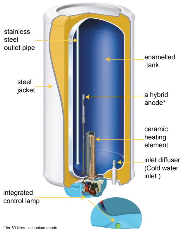
The water heater you have just acquired comprises:
- a tank covered with a protective layer of vitreous enamel;
- an easily replaceable steatite resistance (not necessary to drain the appliance);
- an energy cut-off device in case of an abnormal temperature rise;
- a hybrid anode (for 50 litres: a titanium anode) that emits a low current to permanently protect the tank from corrosion;
- an integrated control lamp to easily see the current operating status.
Maintenance
1. Safety recommendations
- This appliance is not designed to be used by anyone (including children) whose physical, sensory or mental capabilities are reduced or by inexperienced people unless they are being supervised by someone responsible for their safety or they have been instructed in advance in how to use the appliance.
Children should be supervised to ensure that they do not play with the appliance.
2. Water heater maintenance

It is essential to cut all electrical power to the appliance before opening the cover.
2.1 Domestic maintenance
Prevention
A water heater needs little domestic maintenance by the user:
- Operate the safety unit once or twice a month to remove any scale deposits and make sure it is not blocked.
- Periodically check the lamp is working, by helping you to the Troubleshooting Table section, page 54. If it stops or is flashing green rapidly, contact your installer.
- If a problem arises, the appliance doesn't heat or steam is released at tapping points, turn off the power and contact your installer.
To keep your appliance in good working order for many years, you need to have the equipment checked by a professional every two years
Draining
In regions where the water is very hard (Th>20°f), you are advised to treat it. With a softener the hardness of the water should remain above 15^ . The softener has no adverse effect on our guarantee, as long as it is CSTB-approved for France and adjusted according to good practice, regularly checked and maintained:
- Decree no. 2001-1220 of 20 December 2001 and circular DGS/SD 7A.
- Decree no. 2002-571 of 25 November 2002.
- Complies with DTU 60,1.
Proceed as follows when you want to drain your water heater (operation necessary for descending or if the heater must remain out of operation in a room in which frost is possible):
- switch the electricity power supply off
- close the cold water inlet
- open a hot water tap or loosen the hot water fitting.
- open the safety valve drain tap
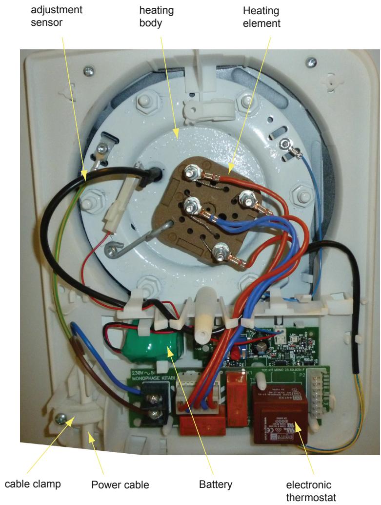
2.2 Description of components
Vertical wall-mounted water heater (VM)
75 to 200 litres :
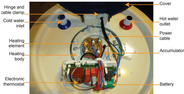
50 litres :
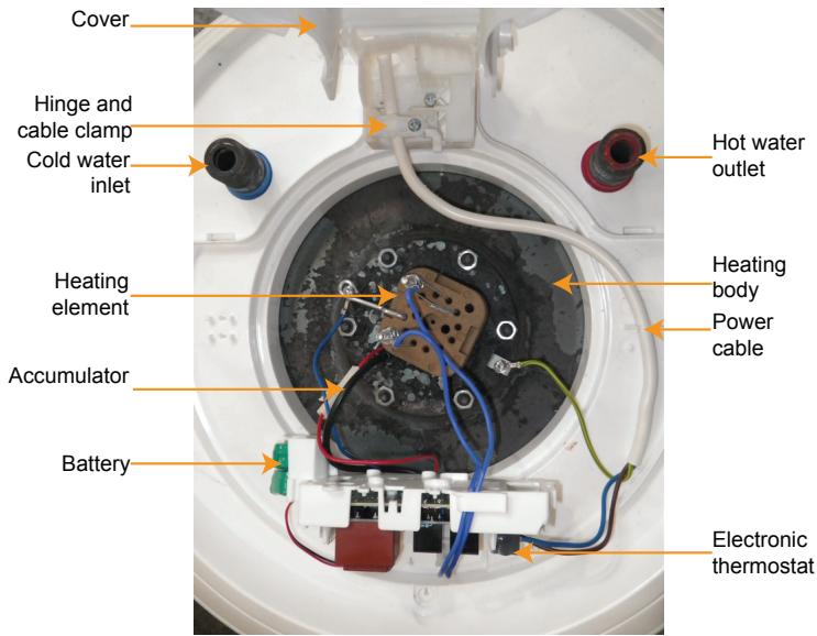
Water heater on pedestal (VS) and wall-mounted horizontal model (HM)
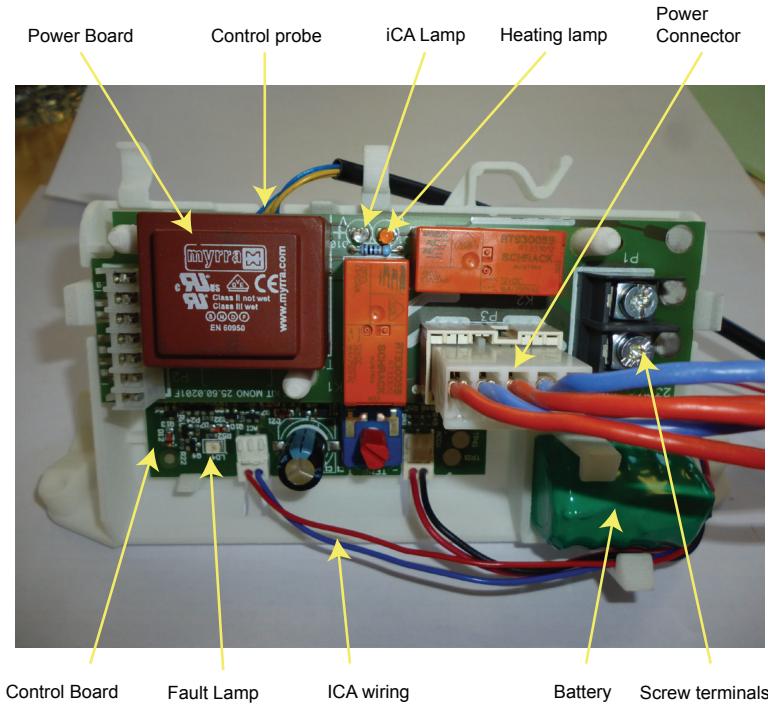
Electronic thermostat
2.3 Servicing by a qualified professional
The procedure for descending the water heater is as follows:
- Cut the appliance's power supply.
- Loosen the screws and remove the cover.
- Disconnect the power cable from the terminals on the thermostat then the earth wire connected to the tank.
- Disconnect the heating element's connector on the power board.
- Disconnect the red wire's connector and unscrew the blue wire's terminal.
-
Unclip the board holder by:
-
tipping it forwards for a vertical wall-mounted model
- unclipping it from the notches of the covering for a vertical on pedestal or horizontal wall-mounted model
Power cable
Earth wire
Connector
Red wire's connector
Vertical wall-mounted
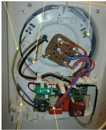
Vertical on pedestal / Horizontal wall-mounted
Earth wire
Red wire's connector
Blue wire's terminal
Power cable
Connector
- Drain the tank and remove the heating unit (heating body and heating element).
- Remove the scale deposited as silt or debris in the bottom of the tank and thoroughly clean the lining. Do not scrape or strike the scale attached to the walls as this may damage the inner lining of the water heater.
- The anode does not need to be inspected or replaced.
- Refit the heating unit using a new gasket and tighten the nuts gradually and reasonably (crosswise).
- Fill the water heater by leaving a hot water tap open; when water flows out of the tap, the water heater is full.
- Check the gasket is water tight, then put the thermostat and its holder back in place, following the above procedure in reverse order.
- Power the water heater up again.
- The next day, check the gasket is water tight and, if necessary, tighten the nuts again slightly.
3. Trouble-shooting
3.1 Troubleshooting by user: control lamp display
| Indicator light n°1 | Lamp status | Meaning | Remarks | |
| Orange | Continuous light (orange) | Normal operation: - Water heating - Corrosion protection provided | The product is running on the mains power | |
| Green | Continuous light (green) | Normal operation Off-peak hours / Continuous: - Hot water available - Corrosion protection provided | The product is running on the mains power | |
| Slow flashing (green) | Normal operation during Peak Hours: - Hot water available - Corrosion protection provided | The product is running on battery | ||
| Rapid flashing (green) | Abnormal operation | Contact your installer or customer service. | ||
| Lamp off | Abnormal operation | No mains power: - Switch to forced operation on your switchboard, and/or - Check the circuit breaker position ◆ If the lamp remains off, contact your installer or customer service.. | ||
| OFF | ○ | |||
3.2 Troubleshooting by installer or customer service: electronic board lamp display

Risk of live bare parts
| Indicator light n°2 | Lamp status | Meaning | Remark / repair |
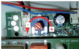
| Red | Flashes 1 3 s | Error 1: faulty battery | Replace the battery |
| Flashes 3 3 s | Error 3: faulty control probe | Replace the control probe | |
| Flashes 7 3 s | Error 7: «Heating when dry» detected | No water in the water heater: - Fill the water heater | |
| Water not conductive enough (soft water): - Contact your installer or customer service.. | |||
| Error 7: faulty corrosion protection system | Open-loop system: - Check all connectors are connected - If the fault persists, replace the heating body |
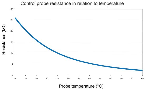
3.3 Checking the control probe
The control probe may be tested using an ohmmeter if necessary:
- between the two blue wires, R < 10 ohms
- between the two yellow wires, refer to the following table that gives the correspondence between resistance and temperature.
Guarantee - Customer Service - Compliance
This appliance complies with Directives 2004/108/EEC regarding electromagnetic compatibility and 2006/95/EEC regarding low-tension systems.
1. Guarantee conditions
The water heater should be installed by a qualified professional in accordance with professional practice, the standards in force and our technical instructions.
It will be used normally and regularly maintained by a specialist.
In these conditions, our guarantee covers the exchange or free supply to our Distributor or Installer of replacements to parts agreed to be defective by our staff, or if necessary of the appliance. It does not cover labour costs, transport costs, or any compensation or extension of the guarantee.
The guarantee takes effect on the date it is installed, the invoice for installation acting as proof. In the absence of documentary evidence, the date the guarantee takes effect will be six months after the date of manufacture shown on the identification plate of the water heater.
The guarantee on a part or a water heater replaced under guarantee ceases at the same time as that of the part or water heater it replaced. (first part invoiced)
The provisions of these conditions of guarantee do not exclude the benefits to the purchaser, or the legal guarantee against faults and hidden defects which apply in all cases under the conditions of articles 1641 et seq. of the civil code.
In no case does the failure of a part justify the replacement of the water heater. Atlantic holds all the spare parts at your disposal for a period of 10 years.
An appliance which is presumed to have caused a fire must be left in place for examination by experts. The person affected should inform his insurance company.

2. Scope of the guarantee
This guarantee does not cover breakdowns due to:
2.1 Abnormal environmental conditions:
- Miscellaneous damage caused by shocks or falls when being handled after it left the factory.
- Installing the appliance in a place subject to frost or a poor environment (damp or aggressive or badly ventilated atmosphere).
- Use of water presenting criteria of aggressivity such as those defined by the DTU Plomberie 60-1 hot-water additive 4 (chloride level, sulphates, calcium, resistivity and methyllorange alkalinity).
Water hardness < 15^ f. - Power supply with substantial voltage peaks (from the grid, lightning, etc.); power supply with minimum or maximum voltage peaks or non-compliant frequencies (NF EN 50160 Electric network).
- Damage resulting from problems that went undetected because of the choice of position (difficult to access) and which could have been avoided if the appliance had been repaired immediately.
2.2 Installation not matching the regulations, standards and good practice, including:
- New safety valve missing or not installed according to standard EN 1487 or modification to the setting, hydraulic system directly installed on the water heater that prevents the safety unit from working (pressure reducing valve, stop valve, etc.)
- No couplings (cast iron, steel or insulating) on the hot water connection pipes, which could cause corrosion.
- Faulty electrical connections: not to standard NFC 15100, incorrectly earthed, insufficiently thick cable, connection using flexible cables, failure to comply with the manufacturer's wiring diagrams.
- Appliance not positioned as shown in the instructions.
- Abnormal tapping corrosion (hot or cold water) due to a faulty connection (bad seal) or faulty dielectric coupling (direct iron/copper contact).
- Electrical protective cover missing or badly installed.
- Cable entry missing or badly installed.
- Fall of an appliance due to inappropriate attachment points.
2.3 Defective maintenance
- Abnormal scale deposits on the elements or safety devices.
- No maintenance of the safety system leading to excess pressure.
- Modification of the original equipment without the maker's approval or use of spares not approved by him.
3. After-sales department
The parts of the water heater that can be replaced are as follows:
Door seal
Electronic thermostat assembly
Heating element
- Sheath for ceramic element
- safety / control probe
battery
Only use spare parts referenced by Atlantic.
To order, please specify the exact code and serial number of the water heater (inset) indicated on the appliance's identification plate placed near the electrical equipment.
All work on the product should be performed by a specialist.
4. Recommendations by GIFAM
Recommendations approved by GIFAM (the Interprofessional Group of Domestic Appliance Manufacturers) on the correct installation and use of the product
4.1 Use
Nature of the product:
- This appliance is intended exclusively to supply domestic hot water.
Abnormal use:
- In the event of malfunction, call in a professional.
- Do not switch on power if the appliance is empty.
Scalds, bacteria:
- For hygiene raisons, hot water should be stored at a high temperature. This temperature may scald.
- Take the necessary precautions, using mixer taps for example, to avoid any accident when drawing water. If the appliance is unused for a long period, run off the nominal capacity of water before the first use.
4.2 Maintenance
- Periodically ensure that the hydraulic safety device is operating correctly as recommended by the manufacturer.
- Before making any adjustments, turn off the appliance.
4.3 Modifications
All modification of the appliance is forbidden. Components should be replaced by a professional using the correct parts.
4.4 End of life
- Before dismantling the appliance, unplug it and empty it.
- Do not burn the appliance. Combustion of certain components may give off poison gas.
- Do not throw your water heater in the garbage, but drop it in a place assigned for this purpose (collection point) where it can be recycled.

- 5 years for the tank for water heaters and their heating elements sheath.
- 5 years for removable equipment : door seal, heating element, thermostat...
■ GARANTIEBON - TE BEWAREN DOOR DE GEBRUKER VAN HET APPARAAT - GARANTIE
Model and serial n^ refer to the identification label of the water heater /