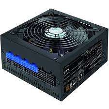
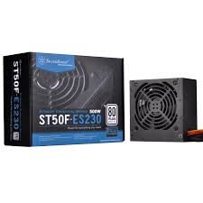
STRIDER PLUS ST75F-P 80PLUS SILVER - Computer power supply SILVERSTONE - Free user manual and instructions
Find the device manual for free STRIDER PLUS ST75F-P 80PLUS SILVER SILVERSTONE in PDF.



| Product Type | Computer Power Supply |
| Brand | SilverStone |
| Model | STRIDER PLUS ST75F-P |
| Certification | 80PLUS Silver |
| Rated Power | 750W |
| Main Connector | ATX 20+4 pin |
| CPU Connector | EPS 8 pin (compatible with 4 pin) |
| PCI-E Connectors | 6 pin and 8 pin |
| SATA Connectors | Yes |
| Peripheral Connectors | Standard 4 pin |
| Floppy Disk Drive Connector | 4 pin (small) |
| Form Factor | ATX |
| Motherboard Compatibility | ATX/BTX, EEB/CEB, server |
| Protections | Overvoltage, overcurrent protection, etc. |
| Fan | Yes (built-in) |
| On/Off Switch | Yes (I/O positions) |
| Voltage Switching | Manual (115V/230V) on non-PFC models |
| Usage | Indoor only |
| Warranty | Manufacturer's warranty according to terms |
Frequently Asked Questions - STRIDER PLUS ST75F-P 80PLUS SILVER SILVERSTONE
User questions about STRIDER PLUS ST75F-P 80PLUS SILVER SILVERSTONE
0 question about this device. Answer the ones you know or ask your own.
Ask a new question about this device
Download the instructions for your Computer power supply in PDF format for free! Find your manual STRIDER PLUS ST75F-P 80PLUS SILVER - SILVERSTONE and take your electronic device back in hand. On this page are published all the documents necessary for the use of your device. STRIDER PLUS ST75F-P 80PLUS SILVER by SILVERSTONE.
USER MANUAL STRIDER PLUS ST75F-P 80PLUS SILVER SILVERSTONE
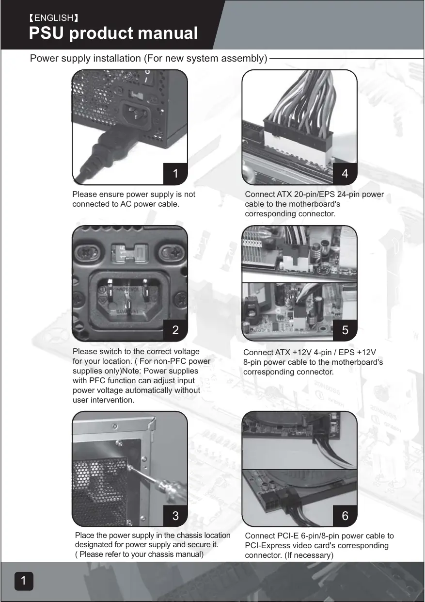
Power supply installation (For new system assembly)
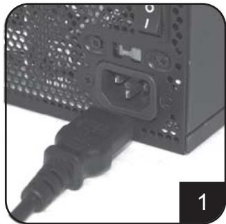
Please ensure power supply is not connected to AC power cable.
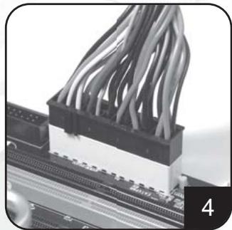
Connect ATX 20-pin/EPS 24-pin power cable to the motherboard's corresponding connector.
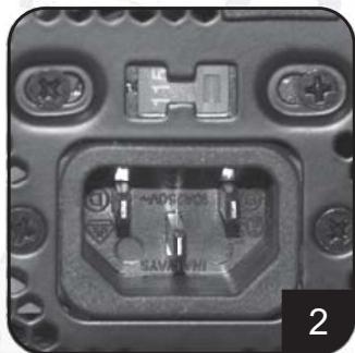
Please switch to the correct voltage for your location. (For non-PFC power supplies only)Note: Power supplies with PFC function can adjust input power voltage automatically without user intervention.
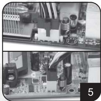
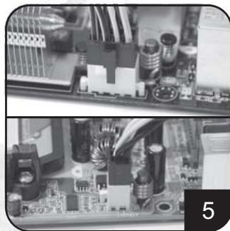
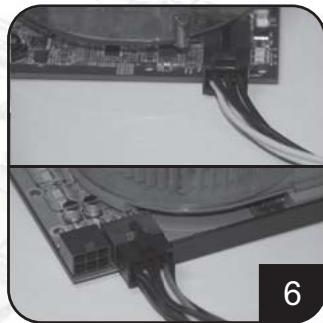
Connect ATX +12V 4-pin / EPS +12V 8-pin power cable to the motherboard's corresponding connector.
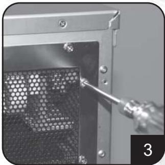
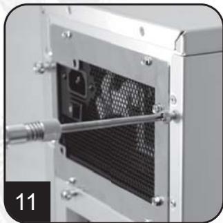
Place the power supply in the chassis location designated for power supply and secure it. (Please refer to your chassis manual)
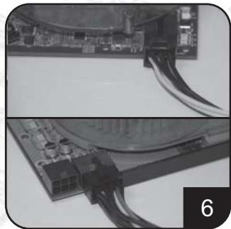
Connect PCI-E 6-pin/8-pin power cable to PCI-Express video card's corresponding connector. (If necessary)
Power supply installation (for new system assembly)
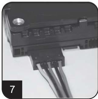
Connect SATA power cables to SATA hard drives or devices.
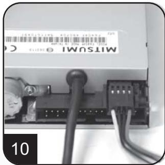
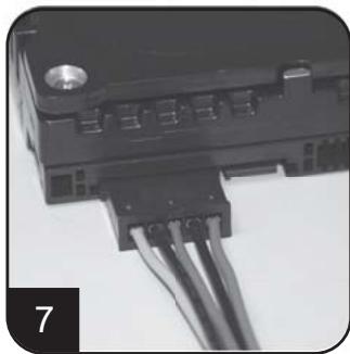
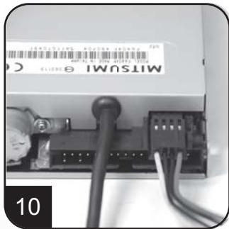
Connect small 4-pin power cable to floppy drives or other compatible devices
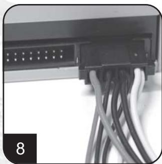
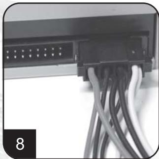
Connect 4-pin peripheral power cables to IDE hard drives, optical drives or other devices.
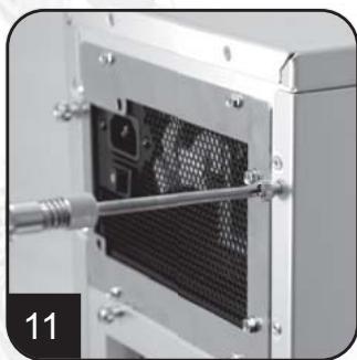
Reinstall chassis's cover, and secure it. (Please refer to the installation of chassis)
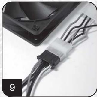
Connect 4-pin peripheral power cables to fans utilizing the peripheral connectors. (DC +12V variety)
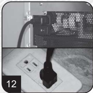
Connect AC power cable to the power supply. (Caution: please do not use extension socket, if using extension socket is necessary, avoid combined usage with other higher powered household appliances such as TV, audio amplifier, etc...)
Power supply installation (For new system assembly)
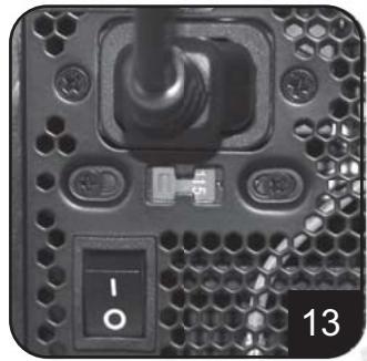
Turn on the power supply by switching to "I" (I/O) mode.
Caution: The power supply is on standby now. System on and off is controlled by the motherboard.
(Pleases refer to the motherboard manual)
Power supply installation (For replacement)
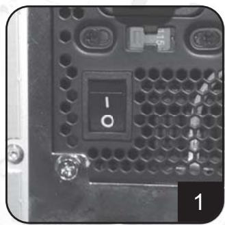
After turning off the system, switch the power supply to "O" position to disable system standby and make sure the system is no longer drawing any power.
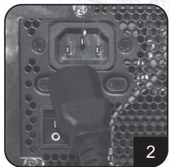
Remove AC power cable from the power supply.
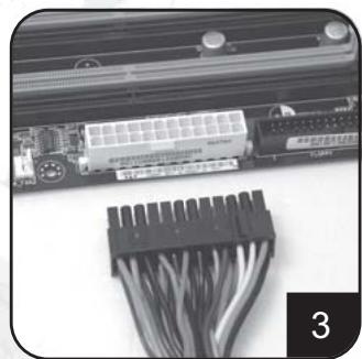
Remove all power supply cables connected to the motherboard, video card, hard drive and other device.
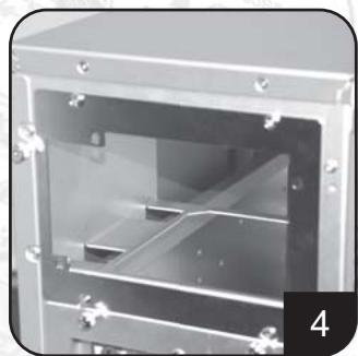
Remove power supply from the chassis. (Please refer to your chassis's installation manual.)
- Please refer now to Step 1 of "Power supply installation (for new system assembly)"
Power supply usage notes and caution
- The power supply includes dangerous high voltage; please do not open the power supply in any condition. Once the power supply enclosure is opened, it will no longer be covered under warranty.
- Please use power supply in safe and dry surroundings.
- Please do not obstruct, insert, or put anything into power supply's vents and any other openings.
- The AC cable included with the power supply has been stringently examined by the factory for defects and quality so please use only the AC cable supplied with your power supply. AC power cable manufactured by a third party may produce incompatible results and possibly cause damage to your system or power supply.
- This product is designed for indoor use only.
Troubleshooting
If your power supply is not operating properly, please refer to the following steps:
- Please make sure the voltage switch is in the correct mode for use in your location (115V or 230V). (For power supplies without PFC function only)
- Please ensure AC power cable is connect to the power supply.
- Please make sure power supply's "I/O" is switched to "I" mode.
- Please double check to see if all motherboard, video card(s), hard drives, and devices' cables are connected correctly.
- Please turn off the power supply by switching the "I/O" to "O" mode. Wait for approximately 5 minutes for the power supply to reset its protection mechanisms, then switch on "I" mode and reboot the system.
Caution: The power supply includes dangerous high voltage; please do not open the power supply under any circumstances. Once the power supply enclosure is opened, it will no longer be covered under warranty.
Power supply connectors

ORANGE +3.3V
GREY PS-ON BURPLE+Vct
YELLOW+12V
TLELOW +12V
ORANGE +3.3V
BLUE -12V 10V ON
BLACK GND SCREEN:POC
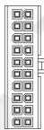
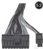
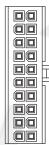
EPS 24-pin motherboard power connector
Support the latest ATX/BTX PC motherboard
Support EEB/CEB server/workstation motherboard
ATX 20-pin motherboard power connector
Support ATX PC motherboard
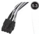
EPS 8-pin CPU +12V power connector
Support Dual CPU server/ workstation
Support latest single CPU system
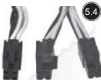
ATX 4-pin CPU +12V power connector
Support latest single CPU system.
PCI-E 6-pin power connector
Support high-end PCI-Express video card, some high-end video cards may require two PCI-E 6 pin connectors.
PCI-E 8 pin power connector
Support high-end PCI-Express video card, some high-end video cards may require another PCI-E 6-pin connector in addition to PCI-E 8pin connector.
SATA hard disk power connector
Support latest SATA hard drives and devices
Standard 4-pin peripheral power connector
Support IDE/SCSI hard drives, optical drives, fans, etc...
Small 4-pin floppy power connector
Support standard floppy drives or compatible devices
Power supply connectors
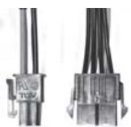

Converting wire
EPS 8-pin connector to convert into ATX 4-pin connector
Caution:
- Please turn off your system and switch to "O" mode on the power supply before attaching or detaching power connectors.
- All power connectors are keyed to prevent incorrect connections. If you cannot connect them easily, please double check to ensure the connector's direction and type before attempting to connect again. Do not attach the connector by force; incorrect connection will damage power supply or devices in your system.
- The converting wire (picture 5.10) can only be attached with EPS 8-pin connector to convert into ATX 4-pin connector. Incorrect connection will damage power supply or devices in your system.
The connectors shown above may differ depending on the model of your power supply.
Warranty
Product component defects or damages resulted in defective production is covered under warranty. Damages resulted with the following conditions will be fixed or replaced under SilverStone's jurisdiction.
- Usage in accordance with instructions provided in this manual, with no misuse, overuse, or other inappropriate actions.
- Damage not caused by natural disaster (thunder, fire, earthquake, flood, salt, wind, insects, animals etc...)
- Product is not disassembled, modified, or fixed. Components not disassembled or replaced.
- Warranty mark/stickers is not removed or broken.
Loss or damages resulted from conditions other than ones listed above are not covered under warranty.
Support ATX PC Motherboard
EPS 8-pin CPU +12V Strombuchse/Stecker
Unterstutz Dual CPU Server/Workstation
Unterstutz neuestes Single CPU System
ATX 4-pin CPU +12V Strombuchse/Stecker
Unterstutz neuestes Single CPU System
PCI-E 6-pin Strombuchse/Stecker
Small 4-pin Floppy Strombuchse/Stecker
EPS 8-pin CPU +12V power connector
CoéuHnTe CnloBoi Ka6eIb ATX 20-pin/ EPS 24-pin c COOTBeTCTByUoIIM KOHNKTopOM MaTePInHcKo IJaTbI.
CoéuHnIte cunlOBoKa6eJIb ATX +12V 4-pin / EPS +12V 8-pin c coOTBeTcTBUOuM KOHNekTopOM MaTePnHcKoI PNaTbl.
CoeHInHTe cINIOBoi Ka6eJIb PCI-E 6-pin/8-pin c COOTBECTBYOULIM KOHNKETOPOM PCI-3KcPpeCCHOI BnDeo KApTBI (B CInyae HeoXoDMOCTN).
PykoBODCTBO npOdyKcIN PSU
YctaHObKa 3JIeKTPoPNTaHn (IINc6OpKn HOBOI CnCTEmbl)
CoeHInHTe cnIObIe Ka6eN SATA c dpaBepaMn JecTKOro DnCKa nn yCtpoiCTBaMn SATA.
CoeHnHTe MaHbKn 4-pin cInnoBoi Ka6ebc dpaBepaMn r6kOro DnCKa nnDpyHMn COBMecTmblIMyUCTpoCTBaMn.
CoedHnHte 4-pin nepi#pepniHbIe cnIObIe Ka6eTn C dpaiBepaMn JxecTKoTo Dmoka IDE,OrTMHeckMn dpaiBepaMn HIN dpyTMMU yCTpoiCTBaMn.
m = 311
+5V
+5V
+5V
GND
ORANGE +3.3V
ORANGE +3.3V
BLACK GND
RED +5V
BLACK GND
RED +5V
BLACK GND DETT 001
GREY PS-ON
PURPLE +5VsbYELLW 171
YELLOW +12V
ORANGE +3.31
BLUE -12V
BLACK GND
GREEN PS-ON
BLACK GND
BLACK GND
BLACK GND N/A
N/C
RED +5V
RED +5V
BLACK GND
BLACK GND
BLACK GND
BLACK GND

YELLOW +12V
YELLOW +12V
YELLOW +12V
YELLOW +12V
BLACK GND
BLACK GND

YELLOW +12V
YELLOW +12V
EPS 24-pin motherboard power connector
KOHHeKToP nHTaHn MaTepHcKo NJIaTbI
EPS 24-pin
IopndepknaeT MaTePHNcky IaTy
cepBepa6oey cTaHcN EEB/CEB
KOHHeKTop nIITaHn MaTePnHcKo nIaTbI ATX 20-pin
KoHneKTop nHTaHnE EPS 8-pin CPU +12V
Iopndepxmbaet cepBep/pa6ouyc taHmio
KoHneKTop nHTaHnA TX 4-pin CPU +12V
IopdepxmbaetnocneHIOO cIcTeMy oDInHOHOro CPU.
KoHHeKToP nHTaHnPA PCI-E 6-pin
ПлдерхиBaet ВьсOKOKаЧeCTBeHHуPCI-3кпрecсHyBndeO KapTy, HeKOTopbIe BьСOKOKaЧeCTBeHHbIe BndeO KapTbI MOrTy Tpe6oBaT bDByx KOннEkTopoB PCI-E 6 pin
KoHHeKTop nHTaHnPAI-C-E 8 pin
ПлдэрхиBaet ВьсOKOKаЧecтBEHHyo PCI-3кпрессHyo BИдeo KapTy, HeKOTopbIe ВьсOKOKaЧecтBEHьe BИдeo KapTbI MOrTy Tpe6ObaTb ДуTORO KOннEkTopa PCI-E 6-pinВДононенHeКONнEkTopy PCI-E8pin.
KoHHeKToP nIITaHnJ XeCTKO rO DnCKa SATA
CtanhapthbI 4-pin nepnpepnHbIKOHHeKTop nHTAHN
IopndepkmbaetpaBepbJkeCTKOrO dncka
IDE/SCSI, onTnueckne dpaBepbl, BeHTINrTopbl n T.I.
Mahehkyi 4-pin KOHekTop nItaHn r6ko Duska
IopndepkXnBaet CtaHapThbIe dpaBebpI r6KOrO DnCKA INN KOM6HnHnpOBaHbIe yCTpoIcTBA
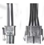

UHyp ppeo6pa3OBAHn
KOMPNEKeT8-ITbIPbKOBOrO CoeINHnTeIg EPS, UTo6 npeo6pa3OBaTb 4-ITbIPbKOBbl CoeINHnTeIb
Пре dioctepexeHne:
IontepnnoBpeKdHnB, Bb3BaHHbIe OndHM n3 dpYnx ycNoBn, He ynomHytbX BblSe, He NOKpbITbI cOrJIaCHO rapaHTnN.
This is the Konkyu Tien's Theorem.
備註
部,如的,有
To be valid, this sheet must be filled out by your salesperson at the time of purchase.
Store :
Purchaser :
Purchase date :
Model No.:
Serial No.:
SilverStone Technology Co., Ltd.
www.silverstonetek.com

- Power supply installation (for new system assembly)
- Power supply usage notes and caution
- Troubleshooting
- Power supply connectors
- EPS 24-pin motherboard power connector
- ATX 20-pin motherboard power connector
- EPS 8-pin CPU +12V power connector
- ATX 4-pin CPU +12V power connector
- PCI-E 6-pin power connector
- PCI-E 8 pin power connector
- SATA hard disk power connector
- Standard 4-pin peripheral power connector
- Small 4-pin floppy power connector
- Converting wire
- Caution:
- Warranty
- EPS 8-pin CPU +12V Strombuchse/Stecker
- ATX 4-pin CPU +12V Strombuchse/Stecker
- PCI-E 6-pin Strombuchse/Stecker
- Small 4-pin Floppy Strombuchse/Stecker
- PykoBODCTBO npOdyKcIN PSU
- KOHHeKToP nHTaHn MaTepHcKo NJIaTbI
- EPS 24-pin
- KOHHeKTop nIITaHn MaTePnHcKo nIaTbI ATX 20-pin
- KoHneKTop nHTaHnE EPS 8-pin CPU +12V
- KoHneKTop nHTaHnA TX 4-pin CPU +12V
- KoHHeKToP nHTaHnPA PCI-E 6-pin
- KoHHeKTop nHTaHnPAI-C-E 8 pin
- KoHHeKToP nIITaHnJ XeCTKO rO DnCKa SATA
- CtanhapthbI 4-pin nepnpepnHbIKOHHeKTop nHTAHN
- Mahehkyi 4-pin KOHekTop nItaHn r6ko Duska
- UHyp ppeo6pa3OBAHn
- Пре dioctepexeHne:
- 備註
Brand : SILVERSTONE
Model : STRIDER PLUS ST75F-P 80PLUS SILVER
Category : Computer power supply