
SCORPION 240 DDS-4 AUTOLOADER - External hard drive QUANTUM - Free user manual and instructions
Find the device manual for free SCORPION 240 DDS-4 AUTOLOADER QUANTUM in PDF.

| Product Type | DDS-4 tape autoloader (external/internal tape drive) |
| Brand | Quantum (formerly Seagate) |
| Model | Scorpion 240 DDS-4 Autoloader |
| Capacity (compressed) | Up to 240 GB with 6 DDS-4 cartridges (40 GB per cartridge) |
| Sustained transfer rate | 5.5 MB/s (compressed), 2.75 MB/s (uncompressed) |
| Interface | Wide SCSI (16-bit) LVD/SE, 68-pin |
| Supported formats | DDS, DDS-1, DDS-2, DDS-3, DDS-4 |
| Number of cartridges | 6 in a removable magazine |
| Power supply | +5 V DC (±7%) and +12 V DC (±10%); power consumption < 17 W operating, < 11 W idle |
| Dimensions (internal) | 5.25-inch full-height bay (134 mm) |
| Weight | Not specified |
| Display | Backlit liquid crystal display (LCD) with multilingual menus |
| Indicators | Clean, tape, drive (with flashing codes) |
| Main functions | Unattended automated backup, tape management, archive, secondary storage |
| Maintenance and cleaning | Regular head cleaning with Seagate cleaning tape model STDMCL (approximately every 25-50 hours depending on tape type) |
| Security | Write protection via jumper on cartridge and switch on magazine; removal prevention via SCSI command |
| Spare parts and repairability | Cleaning tapes, SCSI terminators (ref. 10006525-001); Seagate technical support |
| General information | Compliant with FCC and Canadian Class B regulations; operation in SCSI-1 environment not supported |
Frequently Asked Questions - SCORPION 240 DDS-4 AUTOLOADER QUANTUM
User questions about SCORPION 240 DDS-4 AUTOLOADER QUANTUM
0 question about this device. Answer the ones you know or ask your own.
Ask a new question about this device
Download the instructions for your External hard drive in PDF format for free! Find your manual SCORPION 240 DDS-4 AUTOLOADER - QUANTUM and take your electronic device back in hand. On this page are published all the documents necessary for the use of your device. SCORPION 240 DDS-4 AUTOLOADER by QUANTUM.
USER MANUAL SCORPION 240 DDS-4 AUTOLOADER QUANTUM
© 2000 Seagate Removable Storage Solutions, LLC. All rights reserved
Part Number 100135972
Seagate and the Seagate logo are registered trademarks of Seagate Technology, LLC. Scorpion 240 and the Scorpion logo are either trademarks or registered trademarks of Seagate Removable Storage Solutions LLC. Other product names are registered trademarks or trademarks of their owners.
Seagate reserves the right to change, without notice, product offerings or specifications. No part of this publication may be reproduced in any form without written permission from Seagate Removable Storage Solutions.
Publication Number: 10007066-003, November 13, 2000
#
FCC notice A-5
Introduction A-7
About this user's guide A-7
About the Scorpion 240 autoloder A-7
Before you begin A-9
Precautions A-9
Unpacking and inspection A-9
Installing the internal autoloader A-10
Configuring the internal autoloader A-10
Mounting the internal autoloader A-15
Connecting the SCSI interface cable A-16
Connecting a power cable A-17
Installing the external autoloader A-18
Configuring the external Scorpion 240 A-18
Connecting the power cord A-20
Operation and maintenance A-21
Starting the autoloader A-21
Using cartridges and magazines A-22
About the front-panel buttons A-26
About the front-panel LEDs A-27
About the front-panel LCD display A-30
Cleaning the tape drive A-34
DDS-4 cartridge information A-37
Preparation for shipping A-38
Configuration for UNIX, Novell, and Windows NT operating systems A-40
Operating-system configuration dip switches A-40
Configuration for the Windows NT environment A-41
Configuration for Novell environments A-41
Configuration for the DEC UNIX environment A-43
Configuration for the Sun UNIX environment A-45
Configuration for the SGI environment A-47
Configuration for the HP-UX environment A-51
Configuration for the IBM AIX environment A-52
Configuration for SCO UNIX A-53
Configuration for LINUX A-53
Summary of drive specifications A-54
Support services A-56
This equipment generates and uses radio frequency energy and, if not installed and used in strict accordance with the manufacturer's instructions, may cause interference to radio and television reception, which could void the user's authority to operate the equipment. It has been tested and found to comply with the limits for a Class B digital device pursuant to Part 15 of FCC Rules, which are designed to provide reasonable protection against such interference in a residential installation. However, there is no guarantee that interference will not occur in a particular installation. If interference does occur, try to correct it by taking one or more of the following measures:
Reorient or relocate the receiving antenna.
- Increase the separation between the computer and the receiver.
- Connect the computer into an outlet on a circuit different from that to which the receiver is connected.
- Consult the dealer or an experienced radio/television technician for help.
You may find the following booklet prepared by the Federal Communications Commission helpful: How to Identify and Resolve Radio-TV Interference Problems. This booklet (Stock No. 004-000-00345-4) is available from the U.S. Government Printing Office, Washington, DC 20402.
This equipment complies with the limits for Class B digital apparatus in accordance with Canadian Radio Interference Regulations.
This user's guide contains information on installing and operating the Scorpion 240 DDS-4 autoloader.
About the Scorpion 240 autoloder
The Seagate internal Autolocator is a fully integrated, intelligent, multicartridge tape system that supports the DDS (Digital Data Storage), DDS-1, DDS-2, DDS-3, and DDS-4 tape formats. It includes a magazine that can accommodate up to six tape cartridges.
The internal autoloader (STDL42401LW) is designed to be installed inside a computer, in a 5.25-inch, full-height drive bay. The external autoloader (STDL62401LW) is a standalone subsystem that connects to a host system using a 68-pin shielded SCSI cable.
Note: The Scorpion 240 will not work in a SCSI-1 environment.
The Scorpion 240 autoloader combines established DDS technology, high density recording and hardware data-compression capability, and Seagate's proven computer-grade DDS tape drive to provide unmatched reliability and performance.
Drive applications
The Scorpion 240 autoloader is ideal for server and network/enterprise applications, including:
- Backup of high-capacity disc drives or disc arrays
- Automated storage management
- On-line, unattended data collection
Near-line secondary storage for text, graphics or multimedia data of all types - Archival storage.
Scorpion 240 capacity and data-transfer rates
The Scorpion 240 provides the following capacities and sustained data-transfer rates, depending upon the type and length of tape media used. These capacities and data-transfer rates are based on a 2:1 data compression. Uncompressed capacities are one half these values.
| Tape format: | DDS | DDS-2 | DDS-3 | DDS-4 |
| Tape length (m) | 90 | 120 | 125 | 150 |
| Single-cartridge capacity (Gbytes) | 4.0 | 8.0 | 24.0 | 40.0 |
| Six-cartridge magazine capacity (Gbytes) | 24.0 | 48.0 | 144.0 | 240.0 |
| Sustained Data-transfer Rate (Mbyte/sec) | 1.83 | 1.83 | 5.5 | 5.5 |
Note. 60-meter DDS tape cannot be used with this drive.
Before you begin
Precautions
Caution. Observe the following precautions to avoid electrostatic damage to the internal autoloader.
- Do not remove the drive from the antistatic bag until you are ready to install it.
- Before you remove the drive from the antistatic bag, touch a grounded metal surface to discharge any static electricity buildup from your body.
- Hold the drive only by its edges and avoid direct contact with any electronic components.
- If you need to put down the drive, lay it on top of the antistatic bag or place it inside the bag.
Unpacking and inspection
Although Seagate autosloaders are inspected and carefully packaged at the factory, damage may occur during shipping. Follow these steps for unpacking the autoloader.
- Inspect the shipping container. Notify your shipper immediately if you find any damage.
- Place the shipping container on a flat, clean, stable surface. Then carefully remove the contents and verify the packing list. If parts are missing or the equipment is damaged notify your Seagate representative.
- Save the drive container and packing materials in case you ever need to ship the drive.
Installing the internal autoloader
This chapter describes how to configure, mount, and attach cables to the internal Scorpion 240 autoloader.
Configuring the internal autoloader
Before you install the internal version of the Scorpion 240 in your computer, you may need to configure the drive to work with your system.
Default settings
The default settings for the internal drive are listed below:
The drive is set for SCSI ID 6.
- Parity checking is enabled.
- SCSI terminator power is disabled.
Data compression is enabled.
Power-on self-test diagnostics are enabled.
- MRS checking is enabled (the drive will not write to non-MRS tapes).
If these default settings are appropriate for your computer system, then continue to "Mounting the internal autoloader" on page A-15.
Changing jumper settings
To change the SCSI ID, parity checking, or termination power, use the jumpers on the back of the drive, as shown in Figure 1 on the following page.
Note. Power down the drive before changing jumpers or dip switches. Changes take effect when the drive restarts.
Figure 1. Jumper pins on the back of the Scorpion 240
Default jumper settings shown (SCSI ID 6, parity checking enabled, and termination power disabled)
Pins:
1-2
3-4
5-6
7-8
9-10
11-12
Function:
SCSI ID bit 0
SCSI ID bit 1
SCSI ID bit 2
SCSI ID bit 3
Parity checking
Termination Power
| SCSI ID=0 | |
| SCSI ID=1 | |
| SCSI ID=2 | |
| SCSI ID=3 | |
| SCSI ID=4 | |
| SCSI ID=5 | |
| SCSI ID=6 | |
| SCSI ID=7 |
SCSI Address Selection (pins 1 through 8)
Each SCSI device on a SCSI bus must have a unique SCSI ID. The SCSI controller or host adapter generally uses ID 7. In some systems, the boot drive uses ID 0 or ID 1.
You can select an appropriate SCSI address used by the drive by placing the appropriate jumpers on pins pairs 1-2 through 7-8, as shown in Figure 1.
Note: SCSI ID numbers 8 through 15 will only be recognized if dip switch 9 is "ON." See page A-14 for details.
Parity checking (pins 9 and 10)
If a jumper is installed on pins 9 and 10, parity checking is enabled. If no jumper is installed, parity checking is disabled, but parity is still generated by the drive.
Terminator power (pins 11 and 12)
If a jumper is installed on pins 11 and 12, terminator power is enabled.
Note: The internal Scorpion 240 does not provide SCSI termination, and therefore should not be installed as the last device in a SCSI chain. See "SCSI termination" on page A-16 for more information.
If the terminator power jumper is installed, be careful not to short the TERMPWR signal to ground. In the event of a short, terminator power to the bus will be interrupted. After the short is removed, a fuse in the drive will automatically reset, restoring terminator power.
Changing dip-switch settings
To change data compression, MRS checking, power-on self-test diagnostics, operating system settings, Wide/Narrow SCSI selection, or the drive's inquiry string, you must use the dip switches on the underside of the internal drive.
Figure 2 shows the location of dip switches on the underside of the internal Scorpion 240. Each of these switches is described in detail on subsequent pages.
Note. Power down the drive before changing jumpers or dip switches. Changes take effect when the drive restarts.
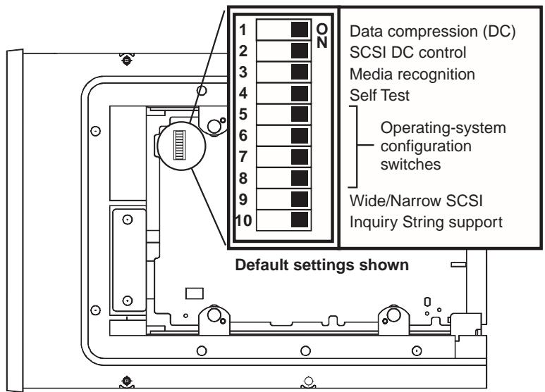
Figure 2. Dip-switch settings for internal Scorpion 240
Data compression (switches 1 and 2)
If switch 1 is ON (the default setting), hardware data compression is enabled when the drive is powered on. If switch 1 is OFF, hardware data compression is disabled at power-on.
If dip switch 2 is ON (the default setting) then SCSI commands can be used to enable or disable hardware data compression. To prevent hardware data compression from being enabled or disabled by SCSI commands, set dip switch 2 to OFF.
Media-recognition system (switch 3)
The media-recognition system allows the drive to determine whether a given tape cartridge conforms to the DDS tape standard. Use of non-DDS media may appear to give
satisfactory results, but the inferior specifications of such media can cause data-integrity problems.
Switch 3 enables or disables the media-recognition system (MRS). If switch 3 is ON (the default setting), the drive reads and writes to MRS media and reads from but does not write to non-MRS media. If switch 3 is OFF, the drive reads or writes both MRS and non-MRS media.
Power-on self-test enable/disable (switch 4)
Switch 4 enables or disables execution of power-on self-test diagnostics when the drive is powered on. If switch 4 is ON (the default setting), the drive performs a power-on self test. If switch 4 is OFF, the drive does not perform a power-on self test.
Operating System configuration (switches 5 through 8)
Switches 5 through 8 are used to configure the drive for use with UNIX, Novell, and Windows NT operating systems. These procedures are described starting on page A-40. The default setting for all four of these switches is ON.
SCSI Wide/Narrow (switch 9)
Switch 9 enables or disables SCSI Wide operation on the SCSI bus. When switch 9 is ON (the default setting), the drive is capable of operating in Wide (16-bit) SCSI mode. When switch 9 is OFF, the drive will only operate as a Narrow (8-bit) SCSI device.
Note: If switch 9 if set to OFF, the drive can only use SCSI ID values 0 through 7.
Inquiry String (switch 10)
Switch 10 is used to select the Vendor ID that the drive returns when queried with a SCSI Inquiry command. When switch 10 is ON (the default setting), the Vendor ID will be "SEAGATE DAT." When switch 10 is OFF the Vendor ID will be "ARCHIVE Python." The "ARCHIVE Python" Vendor ID may be used by independent software vendors to provide software compatibility with previous Seagate DDS tape drives.
Mounting the internal autolocator
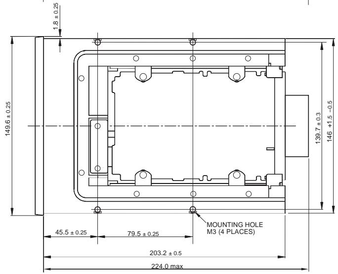
The Scorpion 240 must be mounted horizontally in a 5.25-inch, full-height drive bay. Mount the drive using four M3.0 metric screws on the sides or bottom of the drive, as shown in Figure 3. Do not use screws longer than 4mm or you may damage the drive.
Note. When mounting the drive, make sure that nothing blocks the exhaust fan or the ventilation slots on the bottom and rear of the autoloader.
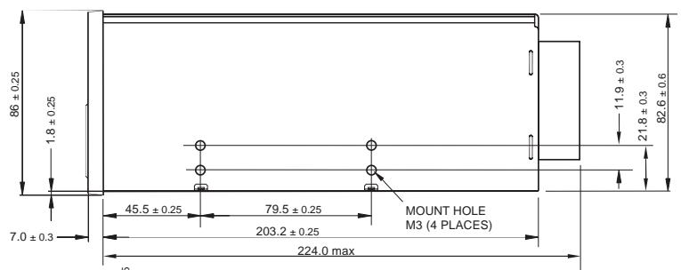
Figure 3. Locations of mounting holes
Connecting the SCSI interface cable
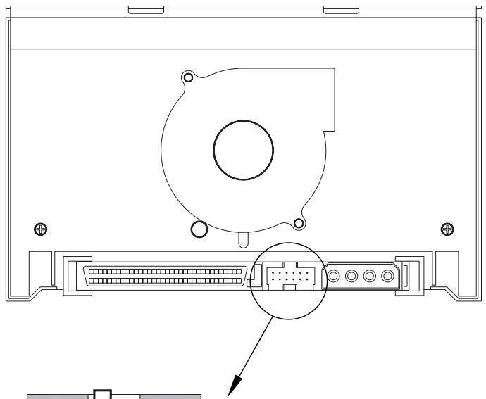
Turn off all power to your computer and drive. Then connect a 68-pin wide internal SCSI cable from your SCSI controller to the SCSI connector on the back of the autoloader. Make sure that pin 1 on the SCSI controller and cable is connected to pin 1 on the drive. Figure 4 shows the location of SCSI pin 1 on the drive's SCSI connector. Pin 1 on the SCSI cable should be indicated by a colored stripe.
Scorpion 240 drives can be used with two different types of SCSI interfaces: Ultra2 SCSI (LVD) or "Wide" (16-bit) single-ended SCSI. The drive can automatically detect whether it is connected to an LVD or single-ended wide SCSI bus.
Note: The Scorpion 240 will not operate properly in a SCSI-1 environment.
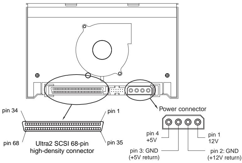
Figure 4. Interface connectors on internal Scorpion 240
SCSI Termination
The internal Scorpion 240 does not provide SCSI termination. For this reason, it should not be the last device on a SCSI chain. Two termination examples are shown in Figure 5 on the following page. If the drive is the only SCSI device, attach the drive to the connector which is next to last on the SCSI
chain and attach an LVD/single-ended multi-mode terminator to the last connector in the chain.
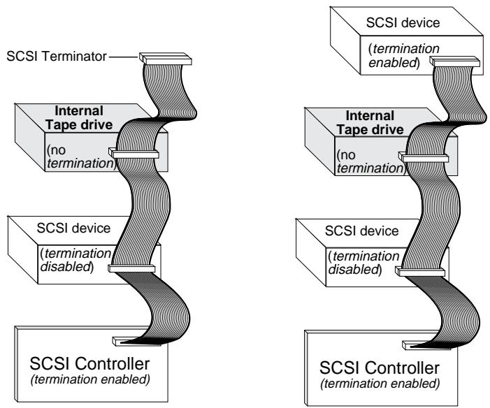
Figure 5. Two SCSI termination examples for the internal Scorpion 240.
Connecting a power cable
Attach a 5/12-volt, four-pin power cable to the power connector on the back of the drive. Figure 4 on the previous page shows the location of the power connector.
The recommended 4-pin power connector for the internal drive is an AMP 1-48024-0 housing with AMP 60617-1 pins or equivalent.
Installing the external autoloader
The external Scorpion 240 is a compact external drive that connects to the host computer as a turnkey subsystem. Installing the external drive involves three simple steps:
- Configuring the drive
- Connecting the SCSI interface cable
- Connecting the power cord
Configuring the external Scorpion 240
The following is the default configuration for the external Scorpion 240:
SCSI ID: 6
Media Recognition System (MRS) checking: enabled.
- Parity checking: enabled.
Data compression: enabled.
Power-on self-test diagnostics: enabled.
- Host operating system: Windows 95/98/NT/2000
Termination power: supplied to the SCSI bus.
Setting the SCSI ID
Make sure that the drive is turned off; then set the SCSI ID for the drive using the push-button switch on the back of the external drive. Figure 6 on the following page shows this switch, as well as the two SCSI interface connectors, on/off switch, and the power-cord connector.
Note: The drive must be restarted for any change in SCSI ID to take effect.
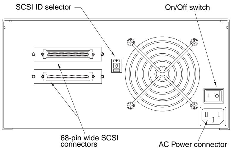
Figure 6. Rear panel of external Scorpion 240
Connecting the SCSI interface cable
The Scorpion 240 provides two 68-pin, shielded connectors on the rear panel of the enclosure. Either connector can be used as a SCSI IN or SCSI OUT connection (you can use either connector to attach the drive to the host computer or to another SCSI device).
Turn off your computer and all SCSI devices. Then attach a SCSI cable from the host adapter or from another (terminated) SCSI device to the Scorpion 240
Note: The Scorpion 240 will not work in a SCSI-1 environment.
SCSI termination
If the Scorpion 240 is the last device or the only device in a SCSI chain, you must install a terminating plug on the unused SCSI connector. See Figure 7 on the following page for two SCSI termination examples. You can purchase a terminator for the Scorpion 240 (part number 10006525-001) on the web at http://buytape.seagate.com.
Figure 7. SCSI termination examples for external Scorpion 240
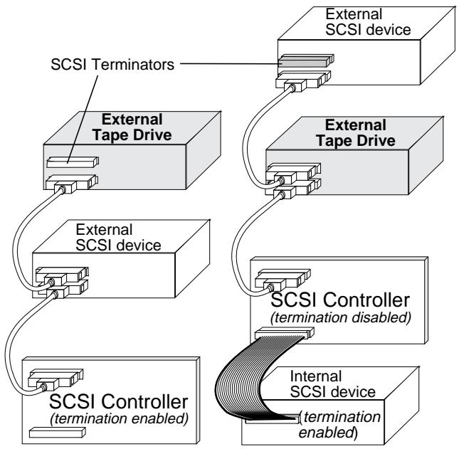
Example 1: SCSI termination in a system that has only external SCSI devices.
Example 2: SCSI termination in a system that has both internal and external SCSI devices.
Connecting the power cord
Attach the power cord securely to the power connector on the back of the drive. The location of the power connector on the external drive is shown in Figure 6 on page A-19.
Operation and maintenance
This section describes how to use your Scorpion 240 autoloader and DDS-4 cartridges. It also explains how to interpret the LEDs and the display on the front of the drive, which are shown in Figure 8.
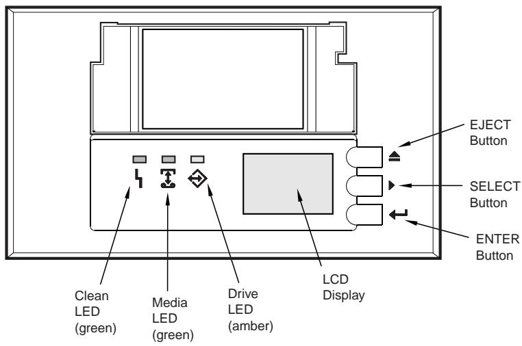
Figure 8. Front view of internal Scorpion 240 autoloader (external drive is similar)
Starting the autolocator
Turn on all SCSI devices attached to your computer before you turn on the computer. When the autoloader is first started, the following events should occur:
- The Clean, Media, and Drive LEDs light up for two seconds, then start flashing.
- The LCD display shows the current SCSI ID, followed by the message, "WAITING SELFTEST."
-
If a magazine is loaded, the LCD display shows the message "SCAN X" while the drive determines which slots in the magazine contain cartridges.
-
As each cartridge is identified by the drive, the cartridge's slot number is displayed on the LCD.
- When all tests are completed, the LCD display shows the message "READY" if a magazine is loaded. If no magazine is loaded, the message "NO MAGAZINE" is shown.
Note. If your computer does not recognize the autoloder, you may need to load the appropriate autoloder module for your backup software. See your backup software installation manual for additional information.
Using cartridges and magazines
Applying labels
When applying labels to a cartridge, observe the following precautions to prevent the cartridge from getting stuck in the autoloader:
- Apply labels firmly, only in recessed label areas.
- Do not let labels extend beyond label areas or fold over the edge of a cartridge.
- Do not apply labels over other labels.
Caution Do not place any labels on the autoloader magazine, since this may cause the tape mechanism to jam.
Loading cartridges in a magazine
Use only approved DDS cartridges in the Scorpion 240.
Approved Seagate cartridges are listed on page A-37. To load cartridges into the magazine, follow these steps:
- Make sure that the cartridges are write protected or write enabled, as necessary. See page A-37 for details.
-
Hold the magazine so that the slot numbers on the side of the magazine are right-side-up.
-
Insert the cartridge into the magazine with the door facing toward the magazine slot, as shown in Figure 9.
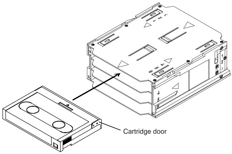
Figure 9. Inserting a cartridge into the autoloader magazine
Loading a magazine into the autolocator
Caution. Do not load a magazine if all the LEDs are flashing; this indicates that the drive is performing a power-on self test.
- Make sure the drive is powered on and operating normally.
- Hold the magazine so that the slot numbers are right-side-up.
- Write protect or write-enable the magazine as appropriate. See page A-38 for details.
- Insert the magazine into the autoloader with the triangles facing into the autoloader bay, as shown in Figure 10 on the following page. Gently push the magazine into the autoloader bay until the autoloader mechanism senses the magazine and pulls it inside.
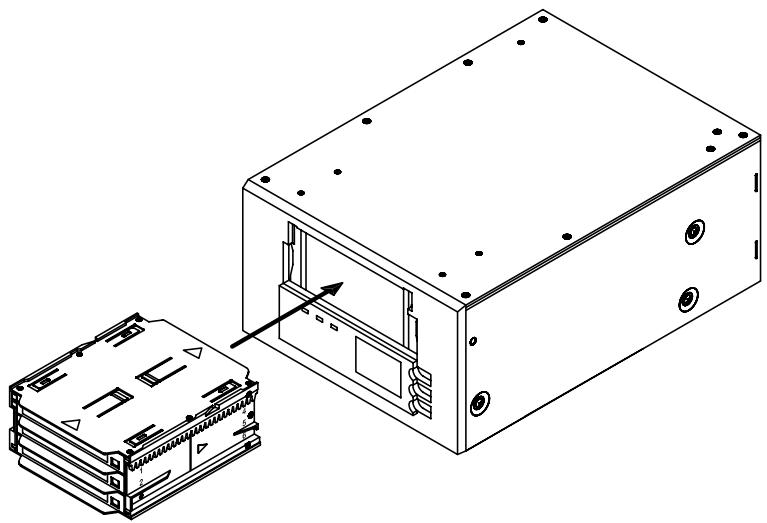
Figure 10. Loading a magazine into the autolocator
Ejecting a cartridge or magazine
To eject the magazine from the autolocator, press the Eject button. If a cartridge is in the drive, the LCD display shows the message "EJECT? PRESS ENTER". Press the Enter button, and wait for the following events to complete:
- The tape rewinds to the beginning-of-partition (BOP) mark.
- If the tape cartridge is not write-protected (read-only), the operating system writes the updated copy of the tape log back to the tape.
- The tape rewinds to the beginning-of-media (BOM) and is unthreaded.
- The changer places the cartridge back into the magazine.
- The magazine is ejected.
If there is no cartridge in the tape drive, the magazine is ejected without delay.
Forcing an eject
If you press the Eject button when the tape drive is busy, the tape drive first completes the current task before responding to the eject request. This way no data is lost.
However, in extreme cases, you may need to force an eject to unload a cartridge, even at the risk of losing the data on the cartridge. A forced eject should only be tried when there is no other way to recover a cartridge.
Caution. If you force an eject, the cartridge may become unreadable and may require erasing or reinitializing by the application software.
You can also force an eject when you need to eject the magazine and there is no cartridge loaded in the drive. If you force an eject when a cartridge is not loaded, the autolocator waits 35 seconds, ejects the magazine, and then resets as though it had been turned off and then turned on.
To force an eject, hold down the Eject button for at least five seconds, then release the button. When you force an eject, the following occurs:
If there is a tape in the drive, the Status Panel displays the message "UNLOAD TAPE X" (where X is the number of the magazine slot which held the tape currently in the drive). After the tape has been returned to the magazine, the display changes to "EJECTING MAGAZINE" and the magazine is ejected.
Note. Because forcing an eject can interrupt an operation, the tape drive might not write the end of data (EOD) mark on the tape before the cartridge is ejected. If the EOD mark is not written on the tape, the tape might be formatted incorrectly and the data on the tape might be lost. However, the data can usually be read up to the point where the error occurred, if a tape is correctly formatted.
If forcing an eject does not successfully remove a cartridge or the magazine, contact Seagate technical support.
Automatic and manual cartridge loading
After cartridges have been loaded into the magazine and the magazine has been inserted into the magazine bay, the autolocator can be left indefinitely for unattended write or read operations (controlled by your backup software).
To load a tape manually, press the SELECT button to select the desired tape slot, then press the ENTER button.
About the front-panel buttons
This section describes the functions of the autoloader buttons. These buttons are shown in Figure 11 below.

Figure 11. Autoloader Front Panel
Eject button
You can use the Eject button to eject the magazine or to unload a cartridge from the drive. After pressing the Eject button, you must press the Enter button to confirm your request.
Select button
You can use the Select button to select individual tape cartridges by their slot numbers (1 through 6), to scroll
through items from menus on the LCD display, and to access loader menus if no magazine is installed.
Enter button
You can use the Enter button to select specific items from menus on the LCD display, to load a cartridge into the drive (after you have selected the cartridge using the Select button), or to confirm that you want to eject the magazine when there is a tape in the drive.
About the front-panel LEDs
As shown in Figure 11 on the previous page, the front panel of the Scorpion 240 Autoloader contains three LEDs that provide information during normal and error conditions. The LED flash codes are summarized below and on the following pages.
Clean LED
The Clean LED functions as follows:
- If the Clean LED is ON continuously, the drive requires cleaning. Use only a Seagate-approved cleaning cartridge to clean the drive, as described on page A-34.
- If the Clean LED is flashing slowly, the tape cartridge currently in use has exceeded a predefined soft-error threshold. This signal is a warning only and does not indicate that data has been lost. If you see this signal, remove the tape at your earliest convenience and clean the drive using a Seagate-approved DDS cleaning cartridge. If, after cleaning the drive and reinserting the original data cartridge, the Clean LED still flashes, then you should use a new cartridge for future backups.
Media LED
The Media LED functions as follows:
- If the Media LED is ON (lit) continuously, a DDS cartridge has been inserted and the drive is operating normally.
- If the Media LED is flashing rapidly, the drive could not write the tape correctly (maximum rewrite count
exceeded) and the write operation failed. Clean the drive heads using a Seagate-approved DDS cleaning cartridge. If you reinsert the original data cartridge and the LED continues flashing, insert a new data cartridge and retry the operation.
Note: As routine maintenance, you should clean the drive heads after every 25 hours of operation when using DDS-1 or DDS-2 tapes or after every 50 hours when using DDS-3 or DDS-4 tapes.
Drive LED
The Drive LED functions as follows:
- If the Drive LED is ON continuously, the drive is reading or writing the tape (that is, SCSI or tape activity is present).
Caution. If you push the Eject button while the Drive LED is ON, you will interrupt any host operation, causing an application error. It may not be possible to append to the tape if a write operation is aborted in this way.
Note: If a SCSI Prevent Media Removal command has been issued, the Drive LED remains ON and the eject button is disabled so that the tape cannot be accidentally ejected.
- If the Drive LED is flashing rapidly, a hardware fault has occurred. If this occurs immediately after powering on the drive, then the Power-On Self Test switch is enabled and a Power-On Self Test has failed. The front panel LEDs may be flashing together. If this occurs contact the Seagate Technical Support department for information. If the Drive LED is flashing rapidly during drive operation, you should attempt to remove the tape by pressing the Eject button. If the tape does not eject within 2 minutes, press and hold the Eject button continuously for more than 5 seconds. The tape should eject within 40 seconds. Contact Seagate Technical Support for more information.
LED Code summary
The following table summarizes LED flash codes for the Scorpion 240.
| LED | Action | Meaning |
| Clean | ON (lit) | Cleaning is required because the drive has been operated for at least 25 hours (DDS-1 and DDS-2) or 50 hours (DDS-3 or DDS-4). |
| Flashing Slowly | The internal error rate threshold has been exceeded and cleaning is required. | |
| Flashing | The cleaning cartridge in the drive has exceeded its useful life. Replace the old cleaning cartridge with a new one. | |
| Media | ON (lit) | A cartridge is inserted and is not generating excessive errors. |
| Flashing | The drive could not write the tape correctly (a write error has occurred). Use a Seagate-approved cleaning cartridge to clean the drive. | |
| Drive | ON (lit) | The drive is reading or writing the tape normally. |
| Flashing Rapidly | A hardware fault occurred. |
About the front-panel LCD display
Figure 12 shows the types of information shown on the front-panel LCD display.
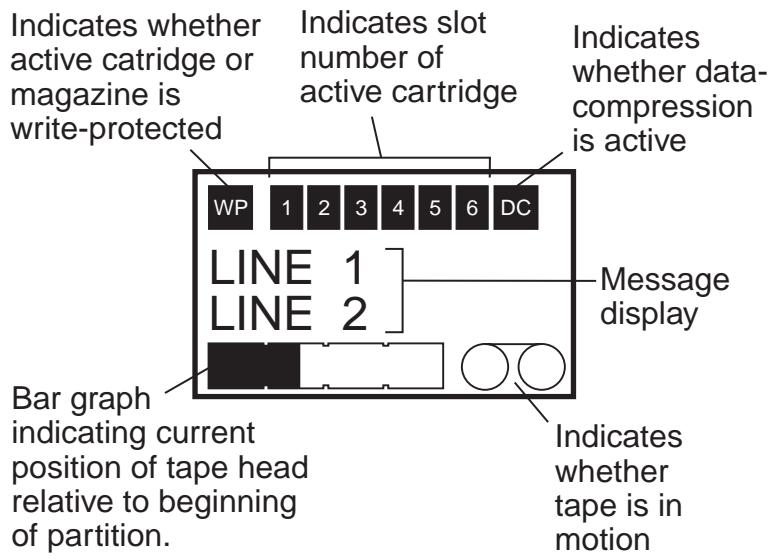
Figure 12. LCD display features
LCD display backlighting
Backlighting on the LCD display is turned on automatically when the autoloader is first powered on and whenever a front-panel button is pushed. The backlight remains on for two minutes, and then shuts off automatically (unless a front-panel button is pressed).
LCD display messages
The table on the following pages describes the messages that may be shown on the LCD display. The messages are listed in alphabetical order. An "X" indicates the number of the currently active cartridge slot.
| LCD Message | Description |
| CASSETTE INSTALL PROBLEM | A cartridge has been inserted into the magazine incorrectly. Eject the magazine from the autolocator (see page A-22); then remove the cartridge from the magazine and reinsert it correctly. |
| CHECK DOOR | The autolocator door is open. |
| CLEANING | The autolocator is loading a cleaning cartridge into the drive. |
| CLEANING REQUIRED | The tape drive requires cleaning. |
| DOOR LOCKED | The autolocator door is locked. |
| DOOR UNLOCKED | The autolocator door is unlocked. |
| DRIVE ERROR 04/XX/XX | There is a problem with the tape drive. For additional information, contact Seagate technical support. |
| ERASE TAPE X | The tape drive is erasing the tape cartridge from slot X. |
| EJECTING MAGAZINE | The autolocator is ejecting the tape magazine. |
| EJECT? PRESS ENTER | A tape resides in the drive and the Eject button has been pressed. Eject confirmation is required before the tape can be ejected. |
| EJECT PREVENT | The autolocator is preventing you from ejecting the magazine because the software has enabled PMR (Prevent Media Removal). |
| FAN FAILURE | There is a problem with the autolocator fan. Contact Seagate technical support. |
| INSERT EMPTY MAGAZINE | The autolocator cannot unload a tape from the tape drive to the magazine because the magazine in the autolocator is fully loaded. Eject the magazine; then insert an empty magazine into the autolocator. For more information on ejecting a magazine, see “Ejecting the magazine” on page A-22. |
| LOADER ERROR 04/XX/XX | There is a problem with the autolocator hardware. For additional information, contact Seagate technical support. |
| LOAD TAPE X | The tape drive is loading the tape cartridge from slot X. |
| MEDIA ERROR 03/XX/XX | There is a problem with the tape cartridge. For additional information, contact Seagate technical support. |
| NO MAGAZINE | There is no magazine in the autolocator. |
| READ TAPE X | The tape drive is reading from a tape |
| READY | The autoloader has scanned all cartridge slots in the magazine and is ready to perform an action. |
| READY TAPE X | There is a tape (from slot X) in the tape drive and the autoloader is ready to accept commands. |
| REPLACE CLEANING TAPE | The cleaning cartridge has been used up and must be replaced with a new cleaning cartridge. |
| REWIND TAPE X | The tape drive is rewinding the tape cartridge from slot X. |
| SCAN X | The autoloader is sequentially scanning the cartridge slots in the magazine. |
| SEARCH TAPE X | The tape drive is searching the tape cartridge from slot X. |
| SELECT X PUSH ENTER | This message displays when you press the Select button. Press the Select button repeatedly to display the desired tape number (X); then press the Enter button to load the selected tape into the drive. |
| SELECT PREVENT | The autoloader is preventing you from selecting a tape to load because a Prevent Media Removal command has been issued by the host. This prevents the tape that is in the drive from being ejected. |
| UNLOAD TAPE X | The tape drive is unloading the tape cartridge from slot X. |
| UPDATING FIRMWARE | The autoloader or tape drive firmware is being updated. |
| WAITING SELFTEST | This message displays while the tape drive is performing a Power-On Self-Test (POST) during startup. |
| WRITE TAPE X | The tape drive is writing to the tape cartridge from slot X. |
Configuring autoloder features using the LCD display
To configure the autolocator using the LCD, first make sure that there is no magazine installed in the autolocator; then press and hold the Select button for five seconds. You can then use the Select button to cycle through the following menus: VERSION, LANGUAGE (Language), CONTRST (Contrast), AUTO/LD (Auto Load), and DOOR. Each of these is described below. To display a particular menu, select the menu item and press the Enter button.
Version menu
In the VERSION menu, you can use the Select button to view the name of the autoloader, its SCSI ID, its firmware level, and the autoloader serial number.
Language menu
In the LAnguAG menu, you can enable the autolocator to display messages on the LCD in English, French, German, Italian, Portuguese, Japanese, or Spanish by scrolling to the appropriate language and pressing the Enter button.
Contrast menu
In the CONTRST menu, you can make the LCD display brighter by pressing the Enter button repeatedly until the desired contrast is displayed. To make the LCD darker, press the Select button repeatedly until the desired contrast is displayed.
Autolog menu
In the AUTO/LD menu, you can enable or disable automatic loading of tape cartridges from the magazine into the tape drive.
Note. This feature should only be used to automate tape loading if application software to support the loader operation is not available.
Most of software available for the Windows NT/2000 platform does support the SCSI commands necessary for loader operation. In this environment we suggest
leaving automatic load disabled (the default state). Check with your software vendor if you are unsure about your particular software application.
In Unix/Linux environments, on the other hand, backup software may not support autoloader operation directly. In this case, the 'offline' command is used to change tapes sequentially (in numerical order by slot number). In Unix/Linux environments, enabling automatic tape loading can allow you to setup an unattended backup.
To enable tape autoloading from within the autolog menu, select "ON" and then press the Enter button. After the magazine is inserted, tape 1 will automatically be loaded into the drive. When autoloading is enabled, the Select button can still be used to exchange tapes, but only in a sequential manner (in numerical order, by slot number).
To turn off autolog mode, display the autolog menu, select "OFF," and then press the Enter button. When autoloading is disabled, tapes can only be loaded or unloaded via the front panel or using application software that has autoloder support.
Door menu
In the DOOR menu, you can lock the autoloader door by selecting "LOCK" and pressing the Enter button. You can unlock it by selecting "UNLOCK" and pressing the Enter button.
Cleaning the tape drive
If excessive magnetic dust or debris collects at one or more of the tape heads, your drive may not be able to read from or write to tape or may experience excessive errors. When the cleaning threshold is exceeded, the autoloader will display the cleaning request in two ways:
- The LCD display will show the message "CLEANING REQUIRED."
The Clean LED will remain ON (lit) continuously.
Note. A slowly flashing Clean LED may indicate that a tape is damaged or is nearing the end of its life. If cleaning the head does not correct the flashing LED condition, replace the cartridge.
Use the table below to determine how often to clean the autoloader.
| Daily Usage (hours) | Optimum cleaning frequency (for DDS-4 tapes) |
| 4 | Twice a month |
| 8 | Weekly |
| 12 or more | Twice a week |
Cleaning procedure
To clean the tape heads on your DDS-4 drive, use only a Seagate-qualified cleaning cartridge designed for DDS-4 drives. You can purchase a Seagate cleaning cartridge, Model STDMCL, on the internet at http://buytape.seagate.com.
Note. The drive cannot recognize audio DAT cleaning cartridges.
Manual cleaning
You can clean the drive manually using the following procedure:
- Place the cleaning cartridge in a magazine slot and insert the magazine into the autolocator.
- Use the Select button to select the slot where you placed the cleaning cartridge.
- Press the Enter button to load the cleaning cartridge into the tape drive. The autoloader starts the cleaning cycle automatically.
-
When the cleaning cycle is complete, if the cartridge is not automatically ejected, press the Eject button to return the cleaning cartridge to the magazine. Press the Eject button again to unload the magazine and remove the cleaning cartridge.
-
Record the date of the cleaning on the cleaning cartridge label.
Each time the cleaning cartridge is loaded, a new, unused portion of cleaning tape is advanced over the entire tape path. The drive does not rewind a cleaning cartridge. After about 30 cleaning cycles, the entire tape is used up, and you must purchase a new cleaning cartridge.
If you insert a cleaning cartridge that has been used up, the cleaning cycle will not be carried out. Instead, the Clean LED will flash rapidly and the LCD will display the message, "REPLACE CLEANING TAPE." The cleaning cartridge will not be returned to the magazine, the Clean LED will stay on, and the LCD will display the message, "CLEANING REQUIRED." In this case, press the Eject button to remove the magazine and replace the old cleaning tape with a new one.
Automated cleaning
If your backup-and-restore software includes a tape-drive head-cleaning feature, you can use the software to clean the drive. Some software packages are preprogrammed to use Slot 6 to clean the drive automatically. The software prompts the autolocator changer to load the cartridge into the tape drive and initiates the cleaning cycle. When the cleaning cycle completes, the tape drive ejects the cleaning cartridge and the changer automatically returns the cartridge to the magazine slot. Refer to your software documentation for details.
If, during automated cleaning, you try to use a cleaning cartridge that has been used up, the cleaning cycle will not be carried out. Instead, the LCD will display the message, "REPLACE CLEANING TAPE". Then the cleaning cartridge will be returned to the magazine, the Clean LED will stay on, and the LCD will display the messages "REPLACE CLEANING TAPE" and "CLEANING REQUIRED". After the software operations are complete you may use the Eject button to remove the old cleaning tape and insert the new cleaning tape.
DDS-4 cartridge information
DAT cartridge compatibility
Seagate DDS-4 drives are designed to use data-grade DDS cartridges, such as those listed below.
Note. 60-meter DDS-1 tapes cannot be used with this drive.
- Model M32000 (DDS-1, 90 meters; 2-Gbyte uncompressed capacity)
- Model M34000 (DDS-2, 120 meters; 4-Gbyte uncompressed capacity)
Model STDM24G (DDS-3, 125 meters, 12-Gbyte uncompressed capacity)
Model STDM40 (DDS-4, 150 meters, 20-Gbyte uncompressed capacity)
Write-protecting the DAT cartridge and magazine
Figure 13 shows how to write-protect or write-enable a DAT tape using the sliding write-protect tab. You can only write data to the tape when the tab is in the closed position.
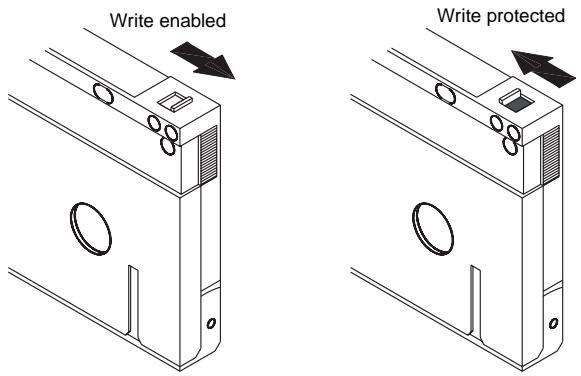
Figure 13. Write-protect tab on the DAT cartridge
Figure 14 shows how to write-protect a Scorpion 240 magazine. To enable writing to the magazine, move the switch upward. To protect all tapes in the magazine from being written to, move the switch down.
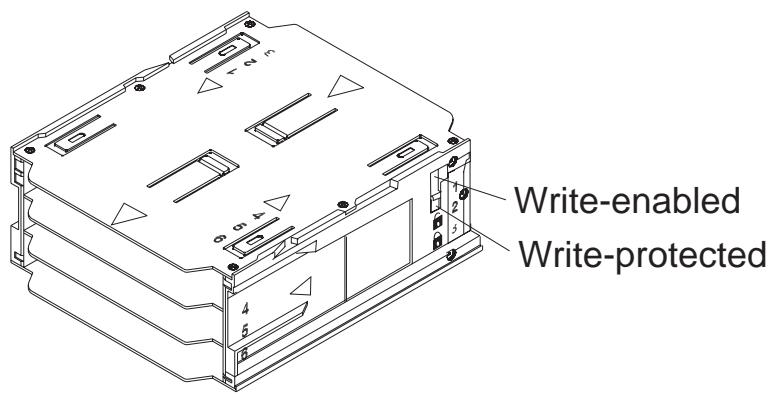
Figure 14. Write-protect switch on autoloader magazine
Preparation for shipping
Before shipping the Scorpion 240, you must secure the autoloader door to prevent damage to the drive. Follow the procedure below to secure the door as the last step before switching off the autoloader:
- Make sure there is no magazine in the autolocator. The LCD should display the message "NO MAGAZINE."
- Press and hold the Select button for 5 seconds. The LCD should show the following menu:
VERSION
LANGUAG
CONTRAST
- Press the Select button four times. The CURER (>) will move down to the word "DOOR," as shown below:
CONTRAST
AUTO/LD
DOOR
- Press the Enter button. The LCD should display the following sub-menu:
DOOR
LOCK
UNLOCK
-
Press the Select button once to move the cursor to "LOCK" and then press the Enter button. The display returns to the menu shown in step 3 above.
-
Wait 5 seconds. The LCD screen will again display the message "NO MAGAZINE." After another 5 seconds, the LCD will display the message, "DOOR LOCKED."
-
Switch off the autoloder
-
Tap the door to make sure it has been successfully locked.
The door is now locked closed and the autoloader is ready to be packed up and shipped. The door is automatically unlocked when the drive is restarted.
Configuration for UNIX, Novell, and Windows NT operating systems
This section explains how to configure the Scorpion 240 for use with various UNIX, Novell, and Windows NT operating systems.
Operating-system configuration dip switches
Figure 15 shows the location of the operating-system configuration dip switches (switches 5 through 8) on the underside of the internal drive.
Note: If the drive is to be used with an operating system other than those described here, these switches should be left in their default positions.
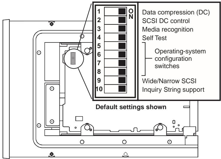
Figure 15 Operating-system configuration dip switches on underside of the Scorpion 240
Configuration for the Windows NT environment
If you use Windows NT 4.0 with the 4mmDAT.SYS driver from Microsoft, you must set Switch 10 (the Inquiry-String switch) to OFF. If you use the STDAT4.SYS driver from Seagate, you can leave the Switch 10 in its default position (ON).
Regardless of which driver you use, all four of the operating-system configuration switches should be left ON (the default positions).
Configuration for Novell environments
The following table summarizes the dip switch settings for various Novell operating systems and drivers. These configurations are described in greater detail in the following paragraphs.
| Operating System / tape driver software | Switch 5 | Switch 6 | Switch 7 | Switch 8 |
| Novell 4.11 w/ native backup applet using TAPEDAI driver or NWTAPE.CDM driver dated before 11/3/99 | OFF | ON | ON | OFF |
| Novell 4.11 w/ native backup applet using NWTAPE driver dated after 11/3/99 | ON | ON | ON | ON |
| Novell 5.x w/ native backup applet using NWTAPE.CDM driver dated before 11/3/99 | OFF | ON | ON | OFF |
| Novell 5.x w/ native backup applet using NWTAPE.CDM driver dated after 11/3/99 | ON | ON | ON | ON |
Novell 4.11
There are two possible ways to configure the Scorpion 240 to work with Novell 4.11, depending on which tape driver you use.
Configuration 1: If you are using the existing Novell TAPEDAI driver or a version of the NWTAPE driver created before 11/3/99, you must change the Operating-System Configuration Dip switches so that switches 5 and 8 are OFF, as shown in the table above. This is different from their default settings (all switches ON).
Configuration 2: If you use the latest Novell NWTAPE driver (available on the Novell web site), the Operating-System Configuration Dip switches should be left in their default positions (all switches ON). From the administrator workstation, place the new NWTAPE driver in the same directory as the TAPEDAI driver (usually the system directory). Edit any .ncf files, such as autoexec.ncf, which call the TAPEDAI driver and replace calls to TAPEDAI with NWTAPE. Do not delete the TAPEDAI driver, because it may come in handy in resolving future problems.
Novell 5.x
There are two possible ways to configure the Scorpion 240 to work with Novell 5.x, depending on which tape driver you use.
Configuration 1: If you are still using the original Novell NWTAPE driver or any version created before 11/3/99, you must change the Operating-System Configuration Dipswitches so that switches 5 and 8 are OFF, as shown in the table on the front of this sheet. This is different from their default settings (all switches ON).
Configuration 2: If you use the latest Novell NWTAPE driver (available on the Novell web site), the Operating-System Configuration Dip switches can be left in their default positions (all switches ON). Before installing the new NWTAPE driver, first rename the old NWTAPE driver (usually found in the system directory). Then copy the new version of NWTAPE into the same directory. Do not delete the old driver, because it might come in handy in resolving future problems.
Configuration for the DEC UNIX environment
Dip switch settings
Before using the Scorpion 240 in a DEC UNIX environment, set the operating-system dip switches as shown below:
| Switch 5 | Switch 6 | Switch 7 | Switch 8 | |
| Setting | OFF | ON | ON | ON |
Digital UNIX Version 4.0 and later
With Version 4.0 of their UNIX operating system, DEC introduced a new method of configuring the CAM SCSI driver. Modify the file /etc/ddr.dbase as follows:
- Look through the file and locate the database entry for the DEC TLZ07 DAT drive
- Copy this entry and paste it later in the file, taking care to maintain the file syntax.
- Modify this new entry as shown below.
SCSIDEVICE
#
Type = tape
Name = "SEAGATE" "DAT"
#
PARAMETERS:
TypeSubClass = rdat
TagQueueDepth = 0
MaxTransferSize = 0x0FFFFFF # (16MB - 1)
ReadyTimeSeconds = 60 # seconds
DENSITY:
#
DensityNumber = 0,3,4,5,6,7
DensityCode = default
CompressionCode = 0x0
Buffered = 0x1
DENSITY: # DensityNumber = 1,2 DensityCode = default CompressionCode = 0x1 Buffered = 0x1
-
Save the database file.
-
Run the following command: ddr_config -c. This takes the default input file, ddr.dbase, and builds a new device database. The new device database is effective immediately, and there is no need to rebuild the kernel.
Digital UNIX Versions earlier than 4.0.
Configure the system by modifying the file cam_data.c. This is located in either /usr/sys/data or /sys/data, depending on the system configuration. The cam_data.c file should be modified as shown below:
- Look through the file to locate the database entry for the "TLZ07 - RDAT" drive.
- Make a copy of this entry and paste it later in the file, taking care to maintain the syntax of the C source.
3.Modify the new entry as shown below.
/* Seagate DAT Drive Returning "SEAGATE DAT" Inquiry */
{"SEAGATE DAT", 14, DEV_TLZ07,
(ALL_DTYPESEQUENTIAL << DTYPE_SHFT) | SZ_RDAT_CLASS,
(struct pt_info *)ccmn_null_sizes, SZ_NO_BLK, (DEC_MAX_REC - 1),
&tlz07_dens, NO_MODE_TAB, SZ_NO_FLAGS,
NO_OPT_CMDS, SZ_READY defy, SZ_NO_QUE,
DD_REQSNS_VAL | DD_INQ_VAL, 36, 64},
- Rebuild the kernel using the doconfig script. Then reboot the system.
Configuration for the Sun UNIX environment
Dip switch settings
Before using the Scorpion 240 in a Sun UNIX environment, set the operating-system dip switches as shown below:
| Switch 5 | Switch 6 | Switch 7 | Switch 8 | |
| Setting | ON | OFF | ON | ON |
Sun OS 4.1.x
To configure SunOS 4.1.x to use the Scorpion 240, you must modify the stddef.h and st_conf.c files (in the directory /usr/sys/scsi/targets), then rebuild the kernel, as described below:
- Modify the stdef.h file by adding a define statement for the Seagate drive like the one shown below:
define ST_TYPE_SEAGATE_DAT
This statement should be added after the last ST_TYPE_ define statement in the file.
- Modify the st_conf.c file by adding the following lines at the end of the device definition list:
/*Seagate DAT drive support */
{ "SEAGATE DAT",7,"SEAGATE",ST_TYPE_SEAGATE_DAT,10240, (ST VARIABLE|ST_BSF|ST_BSR|ST LONG_ERASE|ST_KNOWS_EOD), 5000,5000, {0x0,0x8c,0x8c,0x8c}, {0,0,0,0}
}
- Use the config command to rebuild the kernel and include the new device definition. Refer to the config man page for details.
Solaris 2.x
- To configure Solaris 2.x for compatibility with the Scorpion 240, add the following lines to the file st.conf in the directory /kernel/drv.
tape-config-list= "SEAGATE DAT 06240-XXX","Seagate DAT Drive","SEAGATE_DAT"; SEAGATE_DAT = 1,0x34,0,0xd639,4,0x00,0x8C,0x8C,0x8C,3;
Note: The inquiry string above contains four spaces between the word DAT and the value 06240.
- After modifying the file st.conf, you must reconfigure the kernel by booting the system using the boot -r command
Configuration for the SGI environment
Dip switch settings
Before using the Scorpion 240 in a SGI UNIX environment, make sure that the dip switches are as shown below:
| Switch 5 | Switch 6 | Switch 7 | Switch 8 | |
| Setting | ON | ON | ON | ON |
Note: The main difference between tape drive support in Irix 5.x and 6.x is the introduction for Data Compression switching via software in Irix version 6.2. When running Irix 5.x, the drive will always operate in the compression setting determined by switch 6 on the bottom of the drive (off=compression enabled (default), on=compression disabled).
Irix V5.x
To configure Irix 5.x to use the Scorpion 240, you must modify the file /var/sysgen/master.d/scsi as described below:
- Edit the file /var/sysgen/master.d/scsi and add the following entry:
DATTape,TPDAT,7,12,"SEAGATE","DAT 06240"/DAT,/0,0,0,0,0,0, MTCAN_BSF|MTCAN_BSR|MTCAN_APPEND|MTCAN_SETMK|MTCAN_PART|MTCAN_PREMTCAN_SYNC|MTCAN_SPEOD|MTCAN_CHKRDY|MTCAN_var|MTCAN_SETSZ|MTCAN SILI|MTCAN_SEEK|MTCAN_CHTYPEANY,/* minimum delay on i/o is 12 minutes,to allow the Drives* full error recovery sequence to be performed.*/40,12*60,12*60,12*60,512,512*512
Note: The string above contains four spaces between the word DAT and the value 06240.
- Rebuild the kernel using the autoconfig command (see the autoconfig man page for details). After the kernel is rebuilt you will need to reboot the system again to bring the changes into effect.
Note: Irix 5.3 and later will detect the changes made and automatically rebuild the kernel the next time the system boots.
Irix V6.x through V6.5
To configure Irix 6.x-6.5 to use a Scorpion 240, you must modify the files /var/sysgen/master.d/scsi and /dev/MAKEDEV.d/TPS_base, as described below. After modifying these files you must rebuild the kernel.
- Edit the file /var/sysgen/master.d/scsi and add one of the following entries, depending on your version of IRIX:
For IRIX V6.x through V6.4:
{ DATTAPE, TPDAT, 7, 12, "SEAGATE", "DAT 06240"/*DAT*, 0, 0, {0}, /* This drive uses mode select page 0xf for compression control; * most of the other drives supporting compression use page 0x10 */ MTCAN_BSF|MTCAN_BSR|MTCAN_APPEND|MTCAN_SETMK|MTCAN_PART|MTCAN_PREV|MTCAN_SYNC|MTCAN_SPEOD|MTCAN_CHKRDY|MTCAN_var|MTCAN_SETSZ|MTCAN_SILI|MTCAN_SEEK|MTCAN_CHTYPEANY|MTCAN_COMPRESS, /* minimum delay on i/o is 12 minutes, to allow the Drives * full error recovery sequence to be performed. */ 40, 12*60, 12*60, 12*60, 512, 512*512, 0, (u_char *)0 },
For IRIX V6.5:
{ DATTAPE, TPDAT, 7, 12, "SEAGATE", "DAT 06240"/*DAT*, 0, 0, {0}, /* This drive uses mode select page 0xf for compression control; * most of the other drives supporting compression use page 0x10 */ MTCAN_BSF|MTCAN_BSR|MTCAN_APPEND|MTCAN_SETMK|MTCAN_PART|MTCAN_PREV|MTCAN_SYNC|MTCAN_SPEOD|MTCAN_CHKRDY|MTCAN_var|MTCAN_SETSZ|MTCAN SILI|MTCAN_SEEK|MTCAN_CHTYPEANY|MTCAN_COMPRESS, /* minimum delay on i/o is 12 minutes, to allow the Drives * full error recovery sequence to be performed. */ 40, 12*60, 12*60, 12*60, 3*3600, 512, 512*512, tpsc_default_dens_count, tpsc_default_hwg_dens_names, tpsc_default Alias_dens_names, {0}, 0, 0, 0, (u_char *)0 },
- Edit the file /dev/MAKEDEV.d/TPS_base and make the following modification (this modification is not required on systems running IRIX 6.4 or 6.5).
Locate the area of code which deals with DAT drives. This starts with:
*Drive?type:*DAT*
Then insert the following text before or after the similar entries for other supported devices:
\*Device:\*DAT\*06240*) # DAT drive with compression
mdev=`expr $mdev + 8 `;
mknod prf1c c C_TPSmdev;
;
- Restart the system. Irix 6.x will detect the changes made and automatically rebuild the kernel on startup.
Alternatively, you could manually rebuild the kernel using the autoconfig command (see the autoconfig man page for details), then reboot the system again to bring the changes into effect.
Troubleshooting installations on the SGI platform
Checking the drives inquiry string
It may be useful to confirm the drive's inquiry string. This is done using the mt command. The following command line will retrieve the Inquiry string and other status data from a drive on SCSI bus 1, ID 4.
mt -f /dev/rmt/tps1d4 status
System Interchange Problems
If the following error appears when trying to restore a cpio archive from another system, it is likely that a mistake was made in the installation sequence in section 7.1 above:
Byte swapped Data - re-try with correct device
If this error is encountered, make sure that the correct modifications were made to the file /var/sysgen/master.d/scsi.
Switching Hardware Compression
Irix 6.x provides support for software switching of hardware compression through the use of different device drivers. Drivers including a "c" in the device name should enable compression. You may be able to resolve problems with data compression by installing the latest Irix 6.x patch set.
Configuration for the HP-UX environment
Dip switch settings
Before using the Scorpion 240 in an HP UNIX environment, set the operating-system configuration dip switches as shown below:
| Switch 5 | Switch 6 | Switch 7 | Switch 8 | |
| Setting | ON | ON | OFF | ON |
HP-UX Version 10.2 and 11
Follow the steps below to configure HP-UX systems:
- Log in as root.
- Run the SAM utility.
- Choose the Peripheral Devices option.
- Choose Tape Drives.
- From the Actions menu in the Tape Device Manager window, choose Add.
- Within the Add a Tape Drive window, read the instructions, then click on OK.
- SAM may detect that your HP-UX kernel lacks the drivers necessary to make use of your new tape drive. If so, within the "Device Driver Check" window, read the message and choose the appropriate action. If the chosen option is Build a new kernel and shut down the system immediately, SAM will create a new kernel, and automatically reboot the system. Once the system comes back up, the necessary drivers will be loaded, and the system will be able to use the tape drive.
- If you had to shut down the system in order to physically connect the tape drive, re-enter SAM and repeat steps 3 through 6 above.
- Choose the new tape drive.
- From the Actions menu, choose Create Device Files.
- Press OK and then exit from SAM.
Configuration for the IBM AIX environment
Dip switch settings
Before using the Scorpion 240 in an IBM AIX environment, set the operating-system configuration dip switches as shown below:
| Switch 5 | Switch 6 | Switch 7 | Switch 8 | |
| Setting | ON | OFF | ON | OFF |
AIX Version 3.2 and later
AIX Versions 3.2 and later can be configured to work with the Scorpion 240 by using the SMIT "Other SCSI Tape Drive" option.
Note: To use this procedure, you will need to know the SCSI ID being used by the tape drive.
To configure AIX using the SMIT utility, use the following procedure:
-
Enter SMIT at the Tape Drive menu by typing "smit tape"
-
Select "Add a tape drive"
-
Select the type of tape drive you will be adding. Use the "Other SCSI Tape Drive" option.
-
Select the parent SCSI Adapter from the available list
-
The Add a tape Drive entry fields now appear. Some of the standard options need to be changed to maximize drive performance and functionality:
-
Set the "Connection Address" with the tape drive's Target and LUN (always use 0 for the LUN). In the list, the Target is the first number and the LUN is the second. For example, if the drive is ID 5, choose 5,0
- Set the Fixed "BlockSize" to 1024
-
Set "Density 1" to 140
-
Set the "Maximum delay for the Read/Write command" to 900
-
Press the RETURN key. The drive will be installed in the system database and the appropriate devices created
- Exit SMIT
Controlling data compression under AIX
After you run SMIT, device files will have been created for your new tape drive. Typical filenames are listed below:
/dev/rmt0 /dev/rmt0.1 /dev/rmt0.2 /dev/rmt0.3
/dev/rmt0.4/dev/rmt0.5 /dev/rmt0.6 /dev/rmt0.7
If you enter the configuration information specified in step 5 of the configuration process, devices rmt0, rmt0.1, rmt0.2 and rmt0.3 will cause the drive to write in compressed mode.
Using devices rmt0.4, rmt0.5, rmt0.6 and rmt0.7 will cause the drive to write with compression disabled.
Configuration for SCO UNIX
Before using the Scorpion 240 in an SCO UNIX environment, set the operating-system configuration dip switches as shown below:
| Switch 5 | Switch 6 | Switch 7 | Switch 8 | |
| SCO ODT and Open Server installation, using MAKDEV utility | OFF | ON | ON | OFF |
| SCO UnixWare 7.x | ON | ON | ON | ON |
Configuration for LINUX
Before using the Scorpion 240 in a LINUX environment, make sure the operating-system configuration dip switches are all set to ON, as shown below:
| Switch 5 | Switch 6 | Switch 7 | Switch 8 | |
| Setting | ON | ON | ON | ON |
Summary of drive specifications
| Category | Specification (six-cassette magazine) | |
| Performance specifications | ||
| Tape length/type | (based on 2:1 data compression) | |
| 90 m MP | 24.0 Gbyte (4.0 Gbytes / cassette) | |
| 120 m MP+ | 48.0 Gbyte (8.0 Gbytes / cassette) | |
| 125 m MP++ | 144.0 Gbyte (24.0 Gbytes / cassette) | |
| 150 m MP+++ | 240.0 Gbyte (40.0 Gbytes / cassette) | |
| Recording density (DDS-4) | 122,000 bpi | |
| Track density (DDS-4) | 147.34 tracks/mm | |
| Error recovery | Read-after-write, Reed Solomon ECC, (C3 - 3 levels) | |
| Unrecoverable recording errors | < 1 in 1015 data bits | |
| Head configuration | 2 read heads, 2 write heads | |
| Recording format | DDS-1, DDS-2, DDS-3, DDS-4 | |
| Cartridge dimensions | 2.9 in. x 2.1 in. x 0.4 in. | |
| Transfer rate (sustained) | 2.75 Mbyte/sec uncompressed 5.5 Mbyte/sec compressed | |
| Synchronous transfer rate (burst) | 80 Mbyte/sec max (LVD) 40 Mbyte/sec max (single-ended) | |
| Search speed | 400 X normal speed | |
| Average access time | (single cassette) | |
| 90 m tape | <30 sec | |
| 120 m tape | <40 sec | |
| 125 m tape | <40 sec | |
| 150 m tape | <40 sec | |
| Load Time | ≤ 15 sec | |
| Cassette swap time | ≤ 8.5 sec | |
| Drum rotation speed | 10,000 RPM | |
| Category | Specification (six-cassette magazine) | |
| Environmental Specifications | ||
| Temperature (operating) (nonoperating) | +410to +1130F1(+ 50to + 450C)-400to +1490F2(-400to + 650C) | |
| Thermal gradient | 20°C/minute (no condensation) | |
| Relative humidity (operating) (nonoperating) | 20% to 80% noncondensing0% to 90% noncondensing | |
| Maximum wet bulb temp | 78.80F (260C) | |
| Altitude (operating) (nonoperating-power off) | -100 to +4,575 meters-300 to +15,200 meters | |
| Vibration (nonoperating) | 1.5 g (5 to 500 Hz) | |
| Vibration Sweep Test | 1.20 mm peak-to-peak (5-17 HZ)0.73 g peak (17 to 150 Hz)0.50 g peak (150-500 Hz) | |
| Vibration Sweep Rate | 8 decades per hour | |
| VibrationDwell Test (15 min) | 0.90 mm peak-to-peak (5-17 Hz)0.55 g peak (17-150 Hz)0.25 g peak (150-500 Hz) | |
| Acoustic level idling (A-wt sum) | 47 dBA maximum | |
| Acoustic level operational(A-wt sum) | 60 dBA maximum (measured in suitableenclosure at 3-ft distance and operator height) | |
| Shock (1/2 sine wave)OperatingNonoperating | 10 g's peak, 11 msec50 g's peak, 11 msec | |
| Power specifications | ||
| DC Voltage and tolerance | +12 VDC ± 10% | +5 VDC ± 7% |
| Current (operating/peak) | 0.7 / 2.4 amps | 1.7 / 2 amps |
| Ripple (peak to peak) | ≤ 100 mV | ≤ 100 mV |
| Power dissipation (standby)Power dissipation (operating) | < 11 watts< 17 watts | |
Support services
If you experience problems installing or using your tape drive, Seagate Technical Support can help. If you have general questions about Seagate tape products and applications, please contact Seagate Tape Presales Support.
World-wide services:
World-wide web: A wide variety of technical support services are available on Seagate's World Wide Web site, located at http://www.seagate.com
To purchase tape products or accessories on the internet, go to http://buytape.seagate.com
Seagate E-mail Technical Support: You can e-mail questions or comments to: tapesupport@seagate.com
Regional services
Seagate provides technical support through several regional centers worldwide. These services may include:
- Seagate phone technical support: For one-on-one help, you can talk to a technical support specialist during local business hours. Before calling, note your system configuration and drive model number.
Seagate Technical Support FAX: You can FAX questions or comments to technical support specialists. Responses are sent during local business hours. - SeaFAX: You can use a touch-tone telephone to access Seagate's automated FAX system to receive technical support information by return FAX. This service is available 24 hours daily.
- SeaBOARD: SeaBOARD is Seagate's automated computer bulletin board system, available 24 hours daily. Set your modem to eight data bits, no parity and one stop bit (8-N-1).
Support services in the Americas
Telephone technical support
(you will be directed to a product-specific phone or SEAFAX number)
US customers: 1-800-SEAGATE
International customers: 1-405-936-1234
Seagate Technical Support FAX (US and international):
1-405-936-1683
SeaTDD (Telephone support for the deaf; US and
international): 1-405-936-1687
SeaBOARD (US and international): 1-405-936-1630
Presales Support: 1-800-626-6637
Support services in Europe
For European customer support and SeaFAX, dial the toll-free number for your specific country from the table below. The
Seagate Technical Support FAX number for all European countries is 31-20-653-3513.
| Country | Phone / SeaFAX |
| Austria | 0 800-20 12 90 |
| Belgium | 0 800-74 876 |
| Denmark | 80 88 12 66 |
| France | 0 800-90 90 52 |
| Germany | 0 800-182 6831 (see also SeaBOARD at 49-89-1409331) |
| Ireland | 1 800-55 21 22 |
| Italy | 800-790695 |
| Netherlands | 0 800-732 4283 |
| Norway | 800-113 91 |
| Poland | 00 800-311 12 38 |
| Spain | 900-98 31 24 |
| Sweden | 0 207 90 073 |
| Switzerland | 0 800-83 84 11 |
| Turkey | 00 800-31 92 91 40 |
| United Kingdom | 0 800-783 5177 |
If your country is not listed in the table on the previous page, dial our European call center in Amsterdam at 31-20-316-7222 between 8:30 A.M. to 5:00 P.M. (European central time) Monday through Friday or send a FAX to 31-20-653-3513.
Support services for Africa and the Middle East
For support services in Africa and the Middle East, dial our European call center in Amsterdam at 31-20-316-7222 between 8:30 A.M. to 5:00 P.M. (European central time) Monday through Friday, or send a FAX to 31-20-653-3513.
Support services in Asia and the Western Pacific
For presales and technical support in Asia and the Western Pacific, dial the toll-free number for your specific country. These toll-free numbers are available Monday through Friday from 6:00 A.M. to 10:45 A.M. and 12:00 P.M. to 6:00 P.M. (Australian Eastern Time). If your country is not listed here, please use one of the direct-dial numbers.
| Call Center | Toll-free number | Direct dial number | FAX number |
| Australia | 1800-14-7201 | +61-2-9725-3366 | +61-2-9725-4052 |
| Hong Kong | 800-90-0474 | — | +852-2368 7173 |
| Indonesia | 001-803-1-003-2165 | — | — |
| Japan | — | — | +81-3-5462-2979 |
| Malaysia | 1-800-80-2335 | — | — |
| New Zealand | 0800-443988 | — | — |
| Singapore | 800-1101-150 | +65-488-7584 | +65-488-7528 |
| Taiwan | — | +886-2-2514-2237 | +886-2-2715-2923 |
| Thailand | 001-800-11-0032165 | — | — |
Assistance technique B-62
/*Seagate DAT drive support */
{ "SEAGATE DAT",7,"SEAGATE",ST_TYPE_SEAGATE_DAT,10240, (ST_variable|ST_BSF|ST_BSR|ST LONG_ERASE|ST_KNOWS_EOD), 5000,5000, {0x0,0x8c,0x8c,0x8c}, {0,0,0,0}
}
tape-config-list= "SEAGATE DAT 06240-XXX","Seagate DAT Drive","SEAGATE_DAT"; SEAGATE_DAT = 1,0x34,0,0xd639,4,0x00,0x8C,0x8C,0x8C,3;
DATTape,TPDAT,7,12,"SEAGATE","DAT 06240"/DAT,/0,0,0,0,0,0, MTCAN_BSF|MTCAN_BSR|MTCAN_APPEND|MTCAN_SETMK|MTCAN_PART|MTCAN_PREMTCAN_SYNC|MTCAN_SPEOD|MTCAN_CHKRDY|MTCAN_var|MTCAN_SETSZ|MTCAN SILI|MTCAN_SEEK|MTCAN_CHTYPEANY,/* minimum delay on i/o is 12 minutes,to allow the Drives* full error recovery sequence to be performed.*/40,12*60,12*60,12*60,512,512*512
{ DATTAPE, TPDAT, 7, 12, "SEAGATE", "DAT 06240"/*DAT*, 0, 0, {0}, /* This drive uses mode select page 0xf for compression control; * most of the other drives supporting compression use page 0x10 */ MTCAN_BSF|MTCAN_BSR|MTCAN_APPEND|MTCAN_SETMK|MTCAN_PART|MTCAN_PREV|MTCAN_SYNC|MTCAN_SPEOD|MTCAN_CHKRDY|MTCAN_var|MTCAN_SETSZ|MTCAN SILI|MTCAN_SEEK|MTCAN_CHTYPEANY|MTCAN_COMPRESS, /* minimum delay on i/o is 12 minutes, to allow the Drives * full error recovery sequence to be performed. */ 40, 12*60, 12*60, 12*60, 512, 512*512, 0, (u_char *)0 },
Pour IRIX V6.5:
{ DATTAPE, TPDAT, 7, 12, "SEAGATE", "DAT 06240"/*DAT*, 0, 0, {0}, /* This drive uses mode select page 0xf for compression control; * most of the other drives supporting compression use page 0x10 */ MTCAN_BSF|MTCAN_BSR|MTCAN_APPEND|MTCAN_SETMK|MTCAN_PART|MTCAN_PREV|MTCAN_SYNC|MTCAN_SPEOD|MTCAN_CHKRDY|MTCAN_var|MTCAN_SETSZ|MTCAN SILI|MTCAN_SEEK|MTCAN_CHTYPEANY|MTCAN_COMPRESS, /* minimum delay on i/o is 12 minutes, to allow the Drives
\*full error recovery sequence to be performed. \*/ 40,12\*60,12\*60,12\*60,3\*3600,512,512\*512, tpsc_default_dens_count,tpsc_default_hwg_dens_names, tpsc_default alias_dens_names, {0},0,0,0, 0,(u_char \*)0},
\*Device:\*DAT\*06240*) # DAT drive with compression
mdev=`expr $mdev + 8 `;
mknod prf1c c C_TPSmdev;
;
Byte swapped Data - re-try with correct device
Assistance technique
/*Seagate DAT drive support */
{ "SEAGATE DAT",7,"SEAGATE",ST_TYPE_SEAGATE_DAT,10240, (ST VARIABLE|ST_BSF|ST_BSR|ST LONG_ERASE|ST_KNOWS_EOD), 5000,5000, {0x0,0x8c,0x8c,0x8c}, {0,0,0,0}
}
tape-config-list= "SEAGATE DAT 06240-XXX","Seagate DAT Drive","SEAGATE_DAT"; SEAGATE_DAT = 1,0x34,0,0xd639,4,0x00,0x8C,0x8C,0x8C,3;
DATTape,TPDAT,7,12,"SEAGATE","DAT 06240"DAT,0,0,0,0,0,0, MTCAN_BSF|MTCAN_BSR|MTCAN_APPEND|MTCAN_SETMK|MTCAN_PART|MTCAN_PREVMTCAN_SYNC|MTCAN_SPEOD|MTCAN_CHKRDY|MTCAN_var|MTCAN_SETSZ|MTCAN SILI|MTCAN_SEEK|MTCAN_CHTYPEANY,/*minimum delay on i/o is 12 minutes,to allow the Drives* full error recovery sequence to be performed.*/40,12*60,12*60,12*60,512,512*512
{ DATTAPE, TPDAT, 7, 12, "SEAGATE", "DAT 06240"/*DAT*, 0, 0, {0}, /* This drive uses mode select page 0xf for compression control; * most of the other drives supporting compression use page 0x10 */ MTCAN_BSF|MTCAN_BSR|MTCAN_APPEND|MTCAN_SETMK|MTCAN_PART|MTCAN_PREV|MTCAN_SYNC|MTCAN_SPEOD|MTCAN_CHKRDY|MTCAN_var|MTCAN_SETSZ|MTCAN SILI|MTCAN_SEEK|MTCAN_CHTYPEANY|MTCAN_COMPRESS, /* minimum delay on i/o is 12 minutes, to allow the Drives * full error recovery sequence to be performed. */ 40, 12*60, 12*60, 12*60, 512, 512*512, 0, (u_char *)0 },
IRIX V6.5:
{ DATTape, TPDAT, 7, 12, "SEAGATE", "DAT 06240"/*DAT*, 0, 0, {0}, /* This drive uses mode select page 0xf for compression control; * most of the other drives supporting compression use page 0x10 */ MTCAN_BSF | MTCAN_BSR | MTCAN_APPEND | MTCAN_SETMK | MTCAN_PART | MTCAN_PREV |
MTCAN_SYNC|MTCAN_SPEOD|MTCAN_CHKRDY|MTCAN_var|MTCAN_SETSZ|MTCAN_SILI|MTCAN_SEEK|MTCAN_CHTYPEANY|MTCAN_COMPRESS,/* minimum delay on i/o is 12 minutes, to allow the Drives * full error recovery sequence to be performed. */40,12\*60,12\*60,12\*60,3\*3600,512,512\*512,tpsc_default_dens_count,tpsc_default_hwg_dens_names,tpsc_default alias_dens_names,\{0\},0,0,0,0,(u_char \*)0\},
\*Device:\*DAT\*06240*) # DAT drive with compression
mdev=`expr $mdev + 8 `;
mknod prf1c c C_TPSmdev;
;
Byte swapped Data - re-try with correct device
DensityCode = default CompressionCode = 0x1 Buffered = 0x1
/*Seagate DAT drive support */
{ "SEAGATE DAT",7,"SEAGATE",ST_TYPE_SEAGATE_DAT,10240, (ST_variable|ST_BSF|ST_BSR|ST_long_ERASE|ST_KNOWS_EOD), 5000,5000, {0x0,0x8c,0x8c,0x8c}, {0,0,0,0} }
- Use el commando config para volver a create el kernel e incluya lareshareshareshareshareshareshareshareshareshareshareshareshareshareshareshareshareshareshareshareshareshareshareshareshareshareshareshareshareshareshareshareshareshareshareshareshareshareshareshareshaeshaeshaeshaeshaeshaeshaeshaeshaeshaeshaeshaeshaeshaeshaeshaeshaeshaeshaeshaeshaeshaeshaeshaeshaeshaeshaeshaeshaeshaeshaeshaeshaeshaeshaeshaeshaeshaeshaeshaeshaeshaeshaeshaeshaeshaeshaeshaeshaeshaesha
Solaris 2.x
tape-config-list= "SEAGATE DAT 06240-XXX","Seagate DAT Drive","SEAGATE_DAT"; SEAGATE_DAT = 1,0x34,0,0xd639,4,0x00,0x8C,0x8C,0x8C,3;
DATTape,TPDAT,7,12,"SEAGATE","DAT 06240"/DAT,/0,0,0,0,0,0, MTCAN_BSF|MTCAN_BSR|MTCAN_APPEND|MTCAN_SETMK|MTCAN_PART|MTCAN_PREMTCAN_SYNC|MTCAN_SPEOD|MTCAN_CHKRDY|MTCAN_var|MTCAN_SETSZ|MTCAN SILI|MTCAN_SEEK|MTCAN_CHTYPEANY,/*minimum delay on i/o is 12 minutes,to allow the Drives·full error recovery sequence to be performed.*/40,12*60,12*60,12*60,512,512*512},
{ DATTape, TPDAT, 7, 12, "SEAGATE", "DAT 06240"/*DAT*, 0, 0, {0}, /* This drive uses mode select page 0xf for compression control; most of the other drives supporting compression use page 0x10 */ MTCAN_BSF | MTCAN_BSR | MTCAN_APPEND | MTCAN_SETMK | MTCAN_PART | MTCAN_PREV | MTCAN_SYNC | MTCAN_SPEOD | MTCAN_CHKRDY | MTCAN_var | MTCAN_SETSZ | MTCAN_SILI | MTCAN_SEEK | MTCAN_CHTYPEANY | MTCAN_COMPRESS, /* minimum delay on i/o is 12 minutes, to allow the Drives full error recovery sequence to be performed. */ 40, 12*60, 12*60, 12*60, 512, 512*512, 0, (u_char *)0 },
Para IRIX 6.5:
{ DATTape,TPDAT,7,12,"SEAGATE","DAT 06240"/*DAT*/,0,0,{0}, /* This drive uses mode select page Oxf for compression control; most of the other drives supporting compression use page 0x10^* / MTCAN_BSF|MTCAN_BSR|MTCAN_APPEND|MTCAN_SETMK|MTCAN_PART|MTCAN_PREV| MTCAN_SYNC|MTCAN_SPEOD|MTCAN_CHKRDY|MTCAN_var|MTCAN_SETSZ| MTCAN_SILI|MTCAN_SEEK|MTCAN_CHTYPEANY|MTCAN_COMPRESS, /* minimum delay on i/o is 12 minutes,to allow the Drives full error recovery sequence to be performed. */
\*Device:\*DAT\*06240*) # DAT drive with compression
mdev='expr $mdev + 8';
mknod prflc c C_TPSmdev;
;
Byte swapped Data - re-try with correct device
© 2000 Seagate Removable Storage Solutions, LLC. All rights reserved
癸行番号:100135972
P 为 AQ 中点 PQ = 2 OQ = 1
/*Seagate DAT drive support */
{ "SEAGATE DAT",7,"SEAGATE",ST_TYPE_SEAGATE_DAT,10240, (ST VARIABLE|ST_BSF|ST_BSR|ST LONG_ERASE|ST_KNOWS_EOD), 5000,5000, {0x0,0x8c,0x8c,0x8c}, {0,0,0,0}
}
tape-config-list= "SEAGATE DAT 06240-XXX","Seagate DAT Drive","SEAGATE_DAT"; SEAGATE_DAT = 1,0x34,0,0xd639,4,0x00,0x8C,0x8C,0x8C,3;
DATTape,TPDAT,7,12,"SEAGATE","DAT 06240"/DAT,/0,0,0,0,0,0, MTCAN_BSF|MTCAN_BSR|MTCAN_APPEND|MTCAN_SETMK|MTCAN_PART|MTCAN_PREVMTCAN_SYNC|MTCAN_SPEOD|MTCAN_CHKRDY|MTCAN_var|MTCAN_SETSZ|MTCAN SILI|MTCAN_SEEK|MTCAN_CHTYPEANY,/*minimum delay on i/o is 12 minutes,to allow the Drives*full error recovery sequence to be performed.*/40,12*60,12*60,12*60,512,512*512},
IRIX V6.x~V6.4:
{ DATTAPE, TPDAT, 7, 12, "SEAGATE", "DAT 06240"/*DAT*, 0, 0, {0}, /* This drive uses mode select page 0xf for compression control; * most of the other drives supporting compression use page 0x10 */ MTCAN_BSF|MTCAN_BSR|MTCAN_APPEND|MTCAN_SETMK|MTCAN_PART|MTCAN_PREV|MTCAN_SYNC|MTCAN_SPEOD|MTCAN_CHKRDY|MTCAN_var|MTCAN_SETSZ|MTCAN SILI|MTCAN_SEEK|MTCAN_CHTYPEANY|MTCAN_COMPRESS, /* minimum delay on i/o is 12 minutes, to allow the Drives * full error recovery sequence to be performed. */ 40, 12*60, 12*60, 12*60, 512, 512*512, 0, (u_char *)0 },
IRIX V6.5:
{ DATTAPE, TPDAT, 7, 12, "SEAGATE", "DAT 06240"/*DAT*, 0, 0, {0}, /* This drive uses mode select page 0xf for compression control; * most of the other drives supporting compression use page 0x10 */ MTCAN_BSF|MTCAN_BSR|MTCAN_APPEND|MTCAN_SETMK|MTCAN_PART|MTCAN_PREV|MTCAN_SYNC|MTCAN_SPEOD|MTCAN_CHKRDY|MTCAN_var|MTCAN_SETSZ|MTCAN_SILI|MTCAN_SEEK|MTCAN_CHTYPEANY|MTCAN_COMPRESS, /* minimum delay on i/o is 12 minutes, to allow the Drives * full error recovery sequence to be performed. */ 40, 12*60, 12*60, 12*60, 3*3600, 512, 512*512,
tpsc_default_dens_count, tpsc_default_hwg_dens_names,
tpsc_defaultAlias_dens_names,
{0}, 0, 0, 0,
0, (u_char *) 0 },
\*Device:\*DAT\*06240*) # DAT drive with compression
mdev=`expr $mdev + 8`;
mknod prf1c c C_TPSmdev;
;
Byte swapped Data - re-try with correct device


- #
- FCC notice A-5
- Introduction A-7
- Before you begin A-9
- Installing the internal autoloader A-10
- Installing the external autoloader A-18
- Operation and maintenance A-21
- Configuration for UNIX, Novell, and Windows NT operating systems A-40
- About the Scorpion 240 autoloder
- Drive applications
- Scorpion 240 capacity and data-transfer rates
- Before you begin
- Precautions
- Unpacking and inspection
- Installing the internal autoloader
- Configuring the internal autoloader
- Default settings
- Changing jumper settings
- Pins:
- Function:
- SCSI Address Selection (pins 1 through 8)
- Parity checking (pins 9 and 10)
- Terminator power (pins 11 and 12)
- Changing dip-switch settings
- Data compression (switches 1 and 2)
- Media-recognition system (switch 3)
- Power-on self-test enable/disable (switch 4)
- Operating System configuration (switches 5 through 8)
- SCSI Wide/Narrow (switch 9)
- Inquiry String (switch 10)
- Mounting the internal autolocator
- Connecting the SCSI interface cable
- SCSI Termination
- Connecting a power cable
- Installing the external autoloader
- Configuring the external Scorpion 240
- Setting the SCSI ID
- Connecting the power cord
- Operation and maintenance
- Starting the autolocator
- Using cartridges and magazines
- Applying labels
- Loading cartridges in a magazine
- Loading a magazine into the autolocator
- Ejecting a cartridge or magazine
- Forcing an eject
- Automatic and manual cartridge loading
- About the front-panel buttons
- Eject button
- Select button
- Enter button
- About the front-panel LEDs
- Clean LED
- Media LED
- Drive LED
- LED Code summary
- About the front-panel LCD display
- LCD display backlighting
- LCD display messages
- Configuring autoloder features using the LCD display
- Version menu
- Language menu
- Contrast menu
- Autolog menu
- Door menu
- Cleaning the tape drive
- Cleaning procedure
- Manual cleaning
- Automated cleaning
- DDS-4 cartridge information
- DAT cartridge compatibility
- Write-protecting the DAT cartridge and magazine
- Preparation for shipping
- Configuration for UNIX, Novell, and Windows NT operating systems
- Operating-system configuration dip switches
- Configuration for the Windows NT environment
- Configuration for Novell environments
- Novell 4.11
- Novell 5.x
- Configuration for the DEC UNIX environment
- Dip switch settings
- Digital UNIX Version 4.0 and later
- Digital UNIX Versions earlier than 4.0.
- Configuration for the Sun UNIX environment
- Sun OS 4.1.x
- Solaris 2.x
- Configuration for the SGI environment
- Irix V5.x
- Irix V6.x through V6.5
- Troubleshooting installations on the SGI platform
- Checking the drives inquiry string
- System Interchange Problems
- Switching Hardware Compression
- Configuration for the HP-UX environment
- HP-UX Version 10.2 and 11
- Configuration for the IBM AIX environment
- AIX Version 3.2 and later
- Controlling data compression under AIX
- Configuration for SCO UNIX
- Configuration for LINUX
- Support services
- World-wide services:
- Regional services
- Support services in the Americas
- Telephone technical support
- Support services in Europe
- Support services for Africa and the Middle East
- Support services in Asia and the Western Pacific
- Pour IRIX V6.5:
- Assistance technique
- Para IRIX 6.5:
- IRIX V6.5:
Brand : QUANTUM
Model : SCORPION 240 DDS-4 AUTOLOADER
Category : External hard drive