
HMTS - Electric heating DIMPLEX - Free user manual and instructions
Find the device manual for free HMTS DIMPLEX in PDF.
| Product type | Electric heating mat for underfloor heating |
| Brand | DIMPLEX |
| Model | HMTS |
| Category | Electric heating |
| Use | Supplemental or integral heating for indoor floors (bathrooms, kitchens, etc.) |
| Electrical supply | 230 V ~ 50/60 Hz |
| Maximum permissible current | 16 A (for parallel connection) |
| Differential protection | Mandatory RCD ≤ 30 mA |
| Maximum surface temperature | 80 °C |
| Mat thickness | Approximately 3-4 mm |
| Compatible floor coverings | Tile, parquet, carpet, laminate, PVC |
| Maximum covering thickness | Tile: 30 mm; Parquet: 16 mm; Carpet: 10 mm; Laminate: 8 mm; PVC: 10 mm |
| Minimum distance between cables | 6 cm |
| Installation method | Embedded in tile adhesive or self-leveling compound; mesh facing down (self-adhesive) or up (non-adhesive) |
| Temperature control | Wall thermostat (flush or surface-mounted) with floor sensor; programmable if desired |
| Temperature sensor | Placed in a protective tube between two heating cables |
| Installation | To be carried out by a certified electrician |
| Maintenance | No specific maintenance; normal floor cleaning |
| Warranty | Consult the dealer; requires test certificate and proof of purchase |
| Disposal | Do not dispose of with household waste; follow local regulations |
| Accessories | Cold cable extension available; protective tube for sensor |
Frequently Asked Questions - HMTS DIMPLEX
User questions about HMTS DIMPLEX
0 question about this device. Answer the ones you know or ask your own.
Ask a new question about this device
Download the instructions for your Electric heating in PDF format for free! Find your manual HMTS - DIMPLEX and take your electronic device back in hand. On this page are published all the documents necessary for the use of your device. HMTS by DIMPLEX.
USER MANUAL HMTS DIMPLEX
HM SF, HM TS Heating Mats for Thin-Set Mortar Installation
hm-sfts_ta 10/10/D
Carefully read these instructions before starting the installation work!

All electrical connections must be carried out by a qualified, licensed electrician.
Important installation considerations
- The installation must comply with all relevant VDE regulations, in particular DIN VDE 0100, Part 520 A3.
- The scope of delivery and accessories must be checked for agreement with the planned project.
- The sub-floor surface must be stable and free from vibrations.
- Thermal insulation under the sub-floor surface is absolutely necessary in cases where the mats are installed over soil or unheated spaces.
- When installing the heating mats make sure that self-adhesive mats are placed with the synthetic mesh backing facing down. Non-self-adhesive heating mats should be installed with the synthetic mesh backing facing up.
- The tile adhesive, flexible mortar or levelling compound used must be suitable for the underfloor heating system.
Heating mats, heating cable and cable splices must be completely embedded in the mortar. - Do not bend heating cables at right angles.
Heating cables must not touch or cross each other: Minimum distance: 6 cm. - Do not run heating cables over expansion joints or apparent joints.
- Do not cut or shorten the heating cable nor connect it directly to the power supply.
- At installation, a Residual Current Device is to be provided as protection against indirect contact (sensitivity ≤ 30 mA).
- All relevant VDE and TAB regulations must be complied with.
- The lowest installation temperature of the heating mat is 5^ , the maximum permissible surface temperature is 80^ .
If more than one heating mat is to be connected, the maximum permissible load is 16 A.
Field of Application
This ultra-thin heating mat is used for floor warming and is installed directly under the floor covering. It is suitable both as supplemental heating system or as the primary heating source (heat requirement to be taken into account!). As it is only approx. 3-4 mm thick, this heating mat is mostly used for the remodeling of bathrooms, showers, kitchens, etc.
Maximum thickness of floor covering
| Tiles | 30 mm | = 1,00 W/mK |
| Parquet | 16 mm | = 0,14 W/mK |
| Carpeting | 10 mm | = 0,09 W/mK |
| Laminate | 8 mm | = 0,08 W/mK |
| PVC | 10 mm | = 0,23 W/mK |
HM TS Heating mat construction
The heating cable consists of two parallel heating wires with an additional common PE conductor and an outer sheath. At one end of the heating mat, the two heating wires are connected to each other, at the other end a common cold tail with PE conductor and color coded (blue and black) single conductors is located.
The connection on one side only enables particularly easy installation.
Special accessories are available to extend the cold tail, if required.
HM SF Heating mat construction
The heating wire is attached in a loop pattern to a synthetic mesh thus forming a heating mat with predetermined dimensions. At either end of the heating mat, or the heating wire, a colour coded cold tail (blue and black) is provided for connection to the power supply.
Heating wire and cold tail are provided with an additional protective braiding for connection to the PE conductor.
Special accessories are available to extend the cold tail, if required.
Preparation of the installation area
Prior to the installation of the heating mat, the installation area must be carefully inspected. Any cracks that may be present have to be repaired using epoxy resin. Make sure that the floor surface is free of any sharp objects that could possibly pierce the heating mat.
An edge insulation strip (plastic foam thickness approx. 8 mm) is to be fixed along all walls, support columns, etc.
Installation instructions
Self-adhesive heating mats have to be laid on the floor with the synthetic mesh backing facing down, non-self-adhesive heating mats have to be laid with the synthetic mesh backing facing up, in accordance with the installation plan. The shape indicated on the plan can be achieved by cutting the synthetic mesh backing at the predetermined turning points.
Heating mats should match the desired heated floor area as closely as possible.
Caution! Do not damage the heating wire. Bend the heating mat at the cutting point and lay the next mat length parallel to the first length.
A minimum distance of 6cm between the heating wires must be maintained!
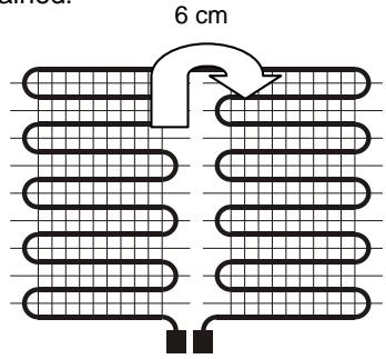
The connecting ends (cold tails) are routed along the outside of the heating mats to the electrical connection box. The heating mats must not cross each other! During installation, avoid walking on the heating mats, if possible.
Prior to embedding the heating mat in mortar, conduct an insulation resistance test, i.e. measure the resistance of the heating mat and record the value in the test/warranty chart. The products suitable for laying the heating mats are available from different manufacturers. Be sure to follow the manufacturer's directions for the mortar product.
Installation on cement screed
- Prime sub-floor and allow to dry.
- Fix self-adhesive heating mat to sub-floor surface and cover with flexible mortar or levelling compound. As an alternative, first apply flexible mortar and press the heating mat into the mortar with the heating mat mesh backing facing down.
- If non-self-adhesive heating mats are used, apply flexible mortar and press the heating mat into the mortar bed with the plastic mesh backing facing up.
- Allow mortar and levelling compound, if any, to dry.
- Even out any irregularities using levelling compound and allow to dry.
Installation on ceramic floors, artificial or natural stone tiles
Existing floor coverings must adhere properly. Remove any contamination such as wax or grease using household cleaners or degreasing agents.
Proceed further as described under "Installation on cement screed" (see above).
Installation on anhydrite floors
Anhydrite floors must be dry, maximum moisture content: 0.5% . Surface may have to be roughened by sanding.
Apply self-levelling cement screed and allow to dry thoroughly.
Proceed further as described under "Installation on cement screed" (see above).
Installation on wood floors and chipboards
The floor must be free from vibrations and dry. Remove any contamination such as wax or grease using household cleaners or degreasing agents.
Rigid foam boards or polyester fiber boards should be screwed or glued onto wooden floor boards.
Heating mats on wooden sub-floors must be embedded in levelling compound or flexible mortar.
Proceed further as described under "Installation on cement screed" (see above).
Floor covering
No additional coverings (e.g. throw rugs or carpets) should be used over the heated area.
Ceramic tiles and natural stone are particularly well suited for use with underfloor heating, but also textile, synthetic material and parquet floor coverings can be used. As a rule, the floor covering must always be laid using an adhesive appropriate for underfloor heating.
Tiles as floor covering
Lay tiles with flexible mortar, then cut off protruding edge insulation strip.
Grout tile seams, apply elastic silicone caulk around edges.
Textile or PVC floor covering
In the case of textile or PVC floor covering, the mat must be covered with a layer of at least 10mm of levelling compound as a mechanical protection measure.
Continuous thermostability of levelling compound: Minimum 50^ .
Installation
The installation of the electric heating system may only be carried out by a qualified, licensed electrician.
The heating system is to be provided with an all-pole disconnect device with a contact gap per pole of at least 3 mm.
A Residual Current Device is to be provided as protection against indirect contact (sensitivity ≤ 30mA ).
The floor sensing probe of the thermostatic controller must be placed in a conduit sealed at one end and installed directly into the heated floor area. Position floor sensor at a point midway between heating cable runs.
Where heating mat cold tails transition from the floor to the wall up to the connection box they must be protected in a conduit.
The cold tail ends of each heating mat are connected to the 230V mains voltage via the control device.
The earthing braid of the heating cable must be connected to the earth conductor. See also the Chapter "Connection of the cold tails".
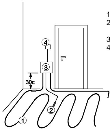
- Heating mat
- Floor sensor, installed in conduit
- Connection box
- Control device
Connection of the cold tails
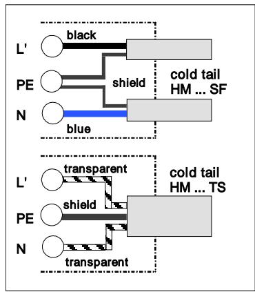
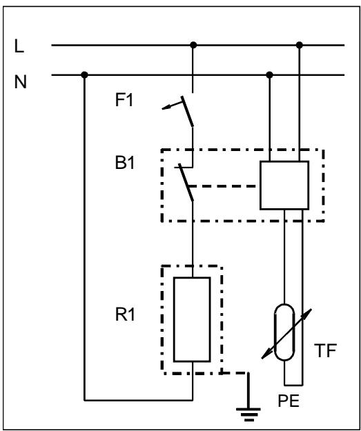
The cold tail ends are to be connected to the wall connection box in accordance with the schematic below.

Caution!
Several heating mats must be connected in parallel!
The maximum permissible current at the switching contact of the controller device must not be exceeded!
L' Terminal for connected phase (230V) via controller device (B1) e.g. temperature thermostat.
PE Terminal of shield of cold tail for line protection and residual current monitoring.
N Neutral terminal of cold tail.
Documentation
The following documents have to be turned over to the operator of the system:
- Installation instructions with completed test record,
- Revision plan showing the location of heating mats, temperature sensor and furniture arrangement as well as spices of heating wires and cold tails.
- Description of floor construction.
Temperature control
Several thermostatic controllers suitable both for surface and flush mounting are available to regulate the floor and/or room temperature. In rooms with several heat sources (e.g. bathrooms) only floor temperature thermostats may be used.
For precise temperature control, a timer can be installed upstream of the underfloor heating system. Optionally, floor temperature controls with programmable setback times and setback temperatures are available.
B1 Control device
F1 Fuse
L Phase 230V~
N Neutral
PE Earth conductor, shield
R1 Heating mat with earthing braid
TF Floor sensing probe
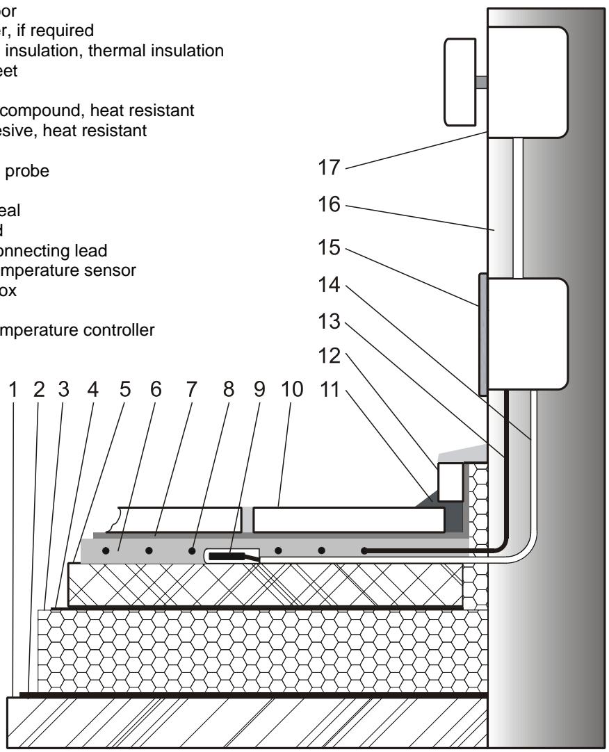
Example of floor construction and electrical installation
- Unfinished floor
- Vapour barrier, if required
- Impact sound insulation, thermal insulation
- Insulating sheet
- Sreed
- Self-levelling compound, heat resistant
- Thin-set adhesive, heat resistant
- Heating mat
- Floor sensing probe
- Tiles
- Elastic joint seal
- Skirting board
- Conduit for connecting lead
- Conduit for temperature sensor
- Connection box
- Wall
- Deep box, temperature controller
Resistance Test and Heat-Up Log
Objekt:
Installation date:
Licensed electrician:
Commissioning date:
| Heating Mat No. | Total resistance (ohm) | Insulation resistance (k-ohm) | ||
| prior to installation | after installation | prior to installation | after installation | |
Important Warranty Notice!
Please contact your local dealer for information on warranty conditions. All warranty claims submitted must be accompanied by a proof of purchase indicating the date of purchase and the completed test and heat-up log.
Disposal notice
The product must not be disposed of with your other household waste.
Trames chauffantes en lit mince HM SF, HM TS
hm-sfts_ta 10/10/D
Parket 16 mm = 0.14 W/mK
Vloerbekleding 10 mm = 0,09 W/mK
Laminaatvloer 8 mm =0,08 W/mK
PVC 10 ~mm = 0.23 ~W / mK

- HM SF, HM TS Heating Mats for Thin-Set Mortar Installation
- Important installation considerations
- Field of Application
- Maximum thickness of floor covering
- HM TS Heating mat construction
- HM SF Heating mat construction
- Preparation of the installation area
- Installation instructions
- Installation on cement screed
- Installation on ceramic floors, artificial or natural stone tiles
- Installation on anhydrite floors
- Installation on wood floors and chipboards
- Floor covering
- Tiles as floor covering
- Textile or PVC floor covering
- Installation
- Connection of the cold tails
- Caution!
- Documentation
- Temperature control
- Example of floor construction and electrical installation
- Resistance Test and Heat-Up Log
- Important Warranty Notice!
- Disposal notice
- Trames chauffantes en lit mince HM SF, HM TS
Brand : DIMPLEX
Model : HMTS
Category : Electric heating