
SCB92MN8 - Combined refrigerator SMEG - Free user manual and instructions
Find the device manual for free SCB92MN8 SMEG in PDF.
| Product type | Combined gas/electric cooker |
| Brand | SMEG |
| Model | SCB92MN8 |
| Width | 90 cm |
| Depth | Approximately 60 cm (depending on model) |
| Height | 85-90 cm (adjustable) |
| Weight | Approximately 70-80 kg (estimate) |
| Electrical supply | 220-240 V ~ 50/60 Hz (or 380-415 V 2N/3N~ depending on model) |
| Gas supply | Natural gas G20 (20 mbar) or LPG G30/G31 (28/37 mbar) |
| Number of gas burners | 5 (auxiliary, semi-rapid, rapid, triple ring, fish burner) depending on version |
| Oven type | Gas with electric option (depending on version) |
| Cooking functions | Grill, rotisserie, fan-assisted, static cooking |
| Safety | Thermocouples on burners, gas shut-off safety, oven door lock |
| Cleaning | Removable grills and burners, separately cleanable door and glass |
| Spare parts | Gas nozzles, gaskets, oven bulbs (T300°C), grills |
| Repairability | Repairability index not provided, but parts available via after-sales service |
| General information | Class 1 appliance, installation by professional, rating plate in compartment |
Frequently Asked Questions - SCB92MN8 SMEG
User questions about SCB92MN8 SMEG
0 question about this device. Answer the ones you know or ask your own.
Ask a new question about this device
Download the instructions for your Combined refrigerator in PDF format for free! Find your manual SCB92MN8 - SMEG and take your electronic device back in hand. On this page are published all the documents necessary for the use of your device. SCB92MN8 by SMEG.
USER MANUAL SCB92MN8 SMEG
1 INSTRUCTIONS FOR SAFE AND PROPER USE 4
2 INSTALLATION OF THE APPLIANCE 6
3 ADAPTATION TO DIFFERENT TYPES OF GAS 9
4 FINAL OPERATIONS 14
5 DESCRIPTION OF FRONT PANEL CONTROLS 16
6 USE OF THE COOKING HOB 18
7 USE OF THE OVEN 21
8 ELECTRONIC PROGRAMMER (ONLY ON EQUIPPED MODELS) 25
9 DIGITAL TIMER (CERTAIN MODELS ONLY) 27
10 ANALOGUE CLOCK (ONLY ON EQUIPPED MODELS) 27
11 CLEANING AND MAINTENANCE 28
12 EXTRAORDINARY MAINTENANCE 30

THESE INSTRUCTIONS ARE VALID ONLY FOR END USER COUNTRIES WHOSE IDENTIFICATION SYMBOLS APPEAR ON THE COVER OF THIS MANUAL.

INSTRUCTIONS FOR THE INSTALLER: these are for the qualified technician who must carry out a suitable check of the gas system, install the appliance, set it functioning and carry out an inspection test.
INSTRUCTIONS FOR THE USER: these contain user advice, description of the commands and the correct procedures for cleaning and maintenance of the appliance.
1 INSTRUCTIONS FOR SAFE AND PROPER USE

THIS MANUAL IS AN INTEGRAL PART OF THE APPLIANCE AND THEREFORE MUST BE KEPT IN ITS ENTIRETY AND IN AN ACCESSIBLE PLACE FOR THE WHOLE WORKING LIFE OF THE COOKER. WE ADVISE READING THIS MANUAL AND ALL THE INSTRUCTIONS THEREIN BEFORE USING THE COOKER. ALSO KEEP THE SERIES OF NOZZLES SUPPLIED. INSTALLATION MUST BE CARRIED OUT BY QUALIFIED PERSONNEL IN ACCORDANCE WITH THE REGULATIONS IN FORCE. THIS APPLIANCE IS INTENDED FOR DOMESTIC USES AND CONFORMS TO CURRENT REGULATIONS IN FORCE. THE APPLIANCE HAS BEEN BUILT TO CARRY OUT THE FOLLOWING FUNCTIONS: COOKING AND HEATING-UP OF FOOD. ALL OTHER USES ARE CONSIDERED IMPROPER.
THE MANUFACTURER DECLINES ALL RESPONSIBILITY FOR IMPROPER USE.
DO NOT LEAVE THE PACKING IN THE HOME ENVIRONMENT. SEPARATE THE VARIOUS WASTE MATERIALS AND TAKE THEM TO THE NEAREST SPECIAL GARBAGE COLLECTION CENTRE.
IT IS OBLIGATORY FOR THE ELECTRICAL SYSTEM TO BE GROUNDED ACCORDING TO THE METHODS REQUIRED BY SAFETY RULES.
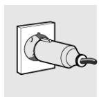
WHEN LINKING UP TO MAINS BY PLUG AND SOCKET, MAKE SURE THAT BOTH ARE COMPATIBLE AND CONNECT BY MEANS OF A POWER CABLE COMPLYING WITH APPLICABLE REGULATIONS.
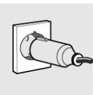
THE SOCKET MUST BE ACCESSIBLE AFTER THE APPLIANCE HAS BEEN BUILT IN. NEVER UNPLUG BY PULLING ON THE CABLE.

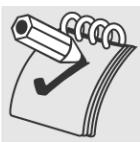
IMMEDIATELY AFTER INSTALLATION CARRY OUT A BRIEF INSPECTION TEST OF THE APPLIANCE, FOLLOWING THE INSTRUCTIONS BELOW. SHOULD THE APPLIANCE NOT FUNCTION, DISCONNECT IT FROM THE SUPPLY AND CALL THE NEAREST TECHNICAL ASSISTANCE CENTRE.
NEVER ATTEMPT TO REPAIR THE APPLIANCE.
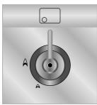
WHEN NOT IN USE, MAKE SURE THAT THE CONTROL KNOBS ARE IN THE CORRECT (OFF) POSITION

NEVER PUT INFLAMMABLE OBJECTS IN THE OVEN: THEY COULD BE ACCIDENTALLY LIGHTED AND CAUSE FIRES.
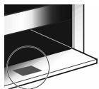
THE I.D. PLATE WITH TECHNICAL DATA, REGISTRATION NUMBER AND BRAND NAME IS POSITIONED VISIBLY IN THE STORAGE COMPARTMENT.
THE PLATE MUST NOT BE REMOVED.
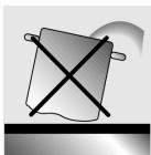
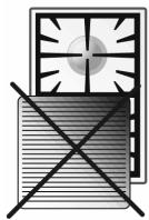
DO NOT PUT PANS WITHOUT PERFECTLY SMOOTH AND FLAT BOTTOMS ON THE COOKING hob GRIDS.
DO NOT USE CONTAINERS OR BROILERS THAT EXTEND BEYOND THE OUTER PERIMETER OF THE HOB.
LOWER THE GLASS COVER SLOWLY AND BY HAND.
WARNING: THE GLASS COVER MAY SHATTER IF IT OVERHEATS. SWITCH OFF ALL RINGS AND WAIT FOR THEM TO COOL DOWN BEFORE CLOSING THE COVER.
DURING USE THE APPLIANCE BECOMES VERY HOT. TAKE CARE NOT TO TOUCH THE HEATING ELEMENTS INSIDE THE OVEN.

THE APPLIANCE IS DESIGNED FOR USE BY ADULTS. DO NOT ALLOW CHILDREN TO GO NEAR OR PLAY WITH IT.
WHEN OPERATING THE GRILL ALL ACCESSIBLE PARTS COULD BECOME VERY HOT: KEEP OUT OF THE WAY OF CHILDREN.
IF THE APPLIANCE IS TO BE POSITIONED ON A PLATFORM IT MUST BE INSTALLED IN SUCH A WAY AS TO PREVENT IT FROM SLIPPING OFF THE FORMER.

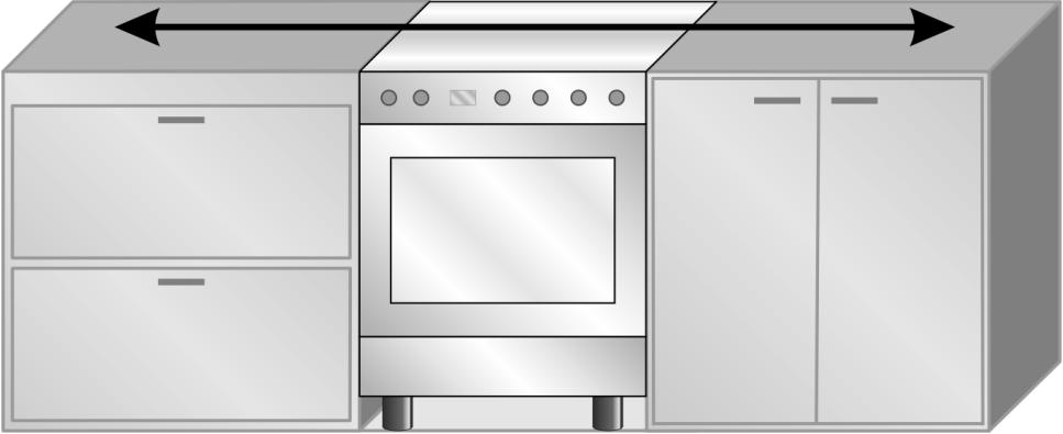
INSTALL THE APPLIANCE SO THAT WHEN DRAWERS OR DOORS OF UNITS INSTALLED AT HOB HEIGHT ARE OPENED, ACCIDENTAL CONTACT WITH PANS ON THE HOB IS NOT POSSIBLE.
THIS APPLIANCE IS MARKED ACCORDING TO THE EUROPEAN DIRECTIVE 2002/96/EC ON WASTE ELECTRICAL AND ELECTRONIC EQUIPMENT (WEEE).
THIS GUIDELINE IS THE FRAME OF A EUROPEAN-WIDE VALIDITY OF RETURN AND RECYCLING ON WASTE ELECTRICAL AND ELECTRONIC EQUIPMENT.
BEFORE THE APPLIANCE IS PUT INTO OPERATION, ALL THE LABELS AND PROTECTIVE FILMS APPLIED INSIDE OR OUTSIDE MUST BE REMOVED.

The manufacturer declines all responsibility for damage to persons or things caused by non-observation of the above prescriptions or by interference with any part of the appliance or by the use of non-original spares.
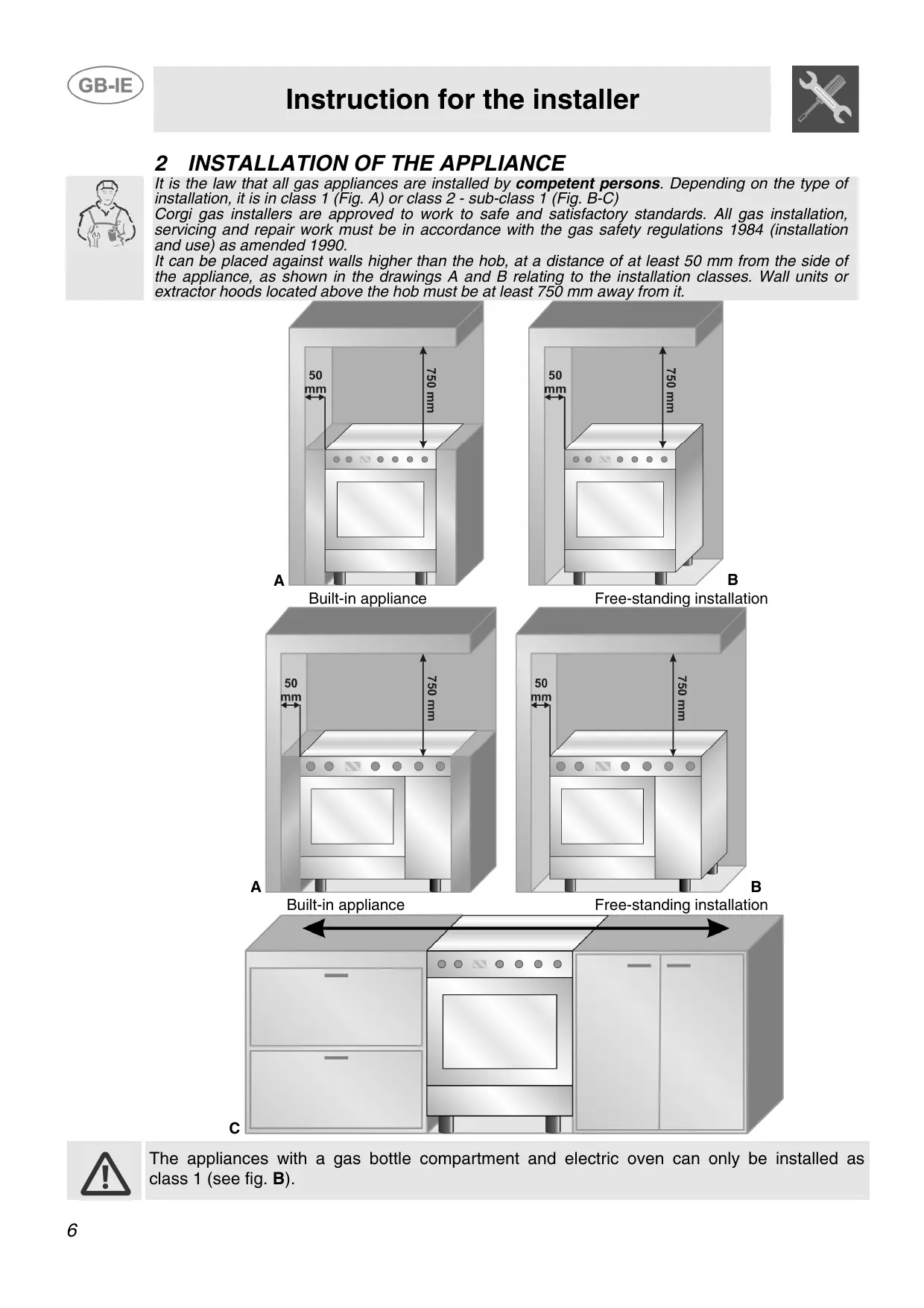
2 INSTALLATION OF THE APPLIANCE
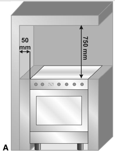
It is the law that all gas appliances are installed by competent persons. Depending on the type of installation, it is in class 1 (Fig. A) or class 2 - sub-class 1 (Fig. B-C)
Corgi gas installers are approved to work to safe and satisfactory standards. All gas installation, servicing and repair work must be in accordance with the gas safety regulations 1984 (installation and use) as amended 1990.
It can be placed against walls higher than the hob, at a distance of at least 50~mm from the side of the appliance, as shown in the drawings A and B relating to the installation classes. Wall units or extractor hoods located above the hob must be at least 750~mm away from it.
Built-in appliance
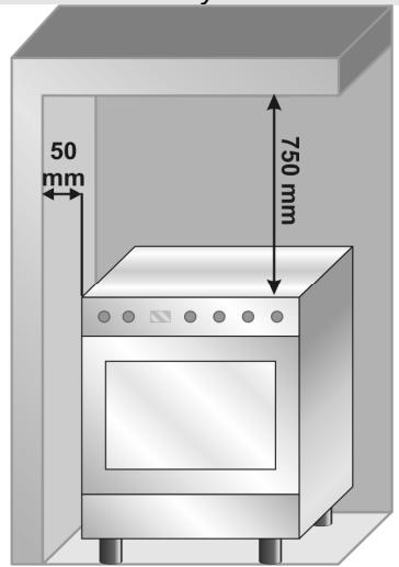
Free-standing installation
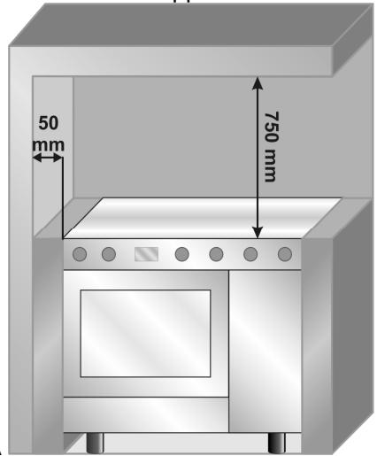
Built-in appliance
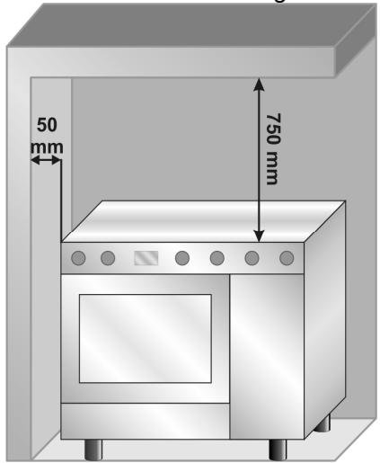
Free-standing installation

The appliances with a gas bottle compartment and electric oven can only be installed as class 1 (see fig. B).
2.1 Electrical connection
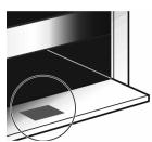
Make sure that the power line voltage matches the specifications indicated on the rating plate located inside the storage compartment.
This rating plate must never be removed.
If the appliance is hooked-up to the supply by means of a fixed connection, install a multipolar cutout device on the line, with contact opening distance equal to or greater than 3mm , located near the appliance and in an easily reachable position.
Hook-up to the supply may be fixed or with plug and socket. In the latter case the plug and socket must be suitable for the cable employed and conform with the regulations in force. Regardless of the type of connection, earthing of the appliance is absolutely obligatory. Before connection make sure that the supply line is suitably earthed. Avoid the use of reducers, adapters or shunts.1
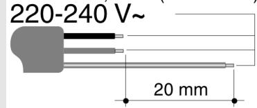
For operation on 220-240 V\~: use an H05RR-F or H05V2V2-F type three-core cable (3 x 2.5 mm² on 90 cm models or 3 x 1.5 on 60 cm models).
1,5 mm²(60 cm mod)
2,5 mm²(90 cm mod)
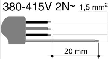
For operation on 380-415 V 2N~ (only for 90 cm models): use an H05RR-F or H05V2V2-F type four-core cable (4 x 1.5 mm²).
For operation on 380-415 V 3N~ (only for 90 cm models): use an H05RR-F or H05V2V2-F type five-core cable (5 x 1.5 mm²).
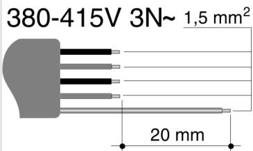
The cable end to be connected to the appliance must be provided with an earth wire (yellow-green) at least 20 ~mm longer.

2.2 Ventilation requirements
The room containing the appliance should have an air supply in accordance with B.S. 5440 part 2 1989.
- All rooms require an opening window or equivalent, and some rooms will require a permanent vent as well.
- For room volumes up to 5m^3 an air vent of 100cm^2 is required.
- If the room has a door that opens directly to the outside, and the room exceeds 1m^3 no air vent is required.
- For room volumes between 5m^3 and 10m^3 an air vent of 50cm^2 is required.
- If there are other fuel burning appliances in the same room B.S. 5440 part 2 1989 should be consulted to determine the air vent requirements.
- This appliance must not be installed in a bed sitting room of less than 20m^3 or in a bathroom or shower room.
Windows and permanent vents should therefore not be blocked or removed without first consulting a Corgi gas installer.
Failure to install appliances correctly is dangerous and could lead to prosecution.
2.3 Connecting to natural and LPG gas
(Pleasesee connection diagram)
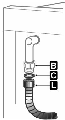
Make the connection to the appliance using flexible bayonet style hose in accordance to B.S. 669. The hose connection at the rear of the appliance has a 12 BSP internal thread. Please use seal C between the flexible connection L and the appliance supply tube B. When making the connection, make sure that no stress of any kind is applied to the cooker and that the hose does not touch any sharp edges.
If connecting to LPG the bayonet hose must have red bands on it.
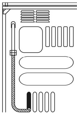
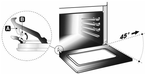
2.3.1 Connection to the gas bottle inside the compartment in the cooker (on some models only)
Open the side door and put in a gas bottle (max. 15 kg). Fit one end of the pipe to the pipe holder and fix it to one of the clamps supplied. Insert the pipe into the bottle compartment through the hole in the back of the cooker as shown in the diagram here. Fit the free end of the pipe to the pressure regulator on the gas bottle: fix it with the second clamp. Check for any leaks using a soapy solution, never with a live flame.
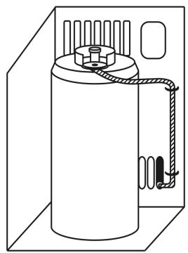
To connect the cooker to a gas bottle, use a piece of regulation rubber pipe 1.4m (± 0.05m) long
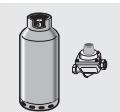
2.3.2 Bottled gas connection (Only on some models)
Use a pressure regulator complaint with the relevant standards and make the connection to the gas cylinder in accordance with the relevant regulations.
Make sure that the gas supply pressure is as stated in the table in point "3.2/3.3 Burner and Nozzle Data Tables".
Screw the small hose connector F onto the large hose connector A and connect the resulting unit to the gas union B (or use the hose connector G for connection straight to the gas union B) and fit the seal C. Fit the ends of the rubber hose H onto the hose connector A+F (or G) and to the outlet union of the pressure reducer on the gas cylinder. Fix the end of the hose H to the hose connector A+F (or G) using the regulation hose clamp I.
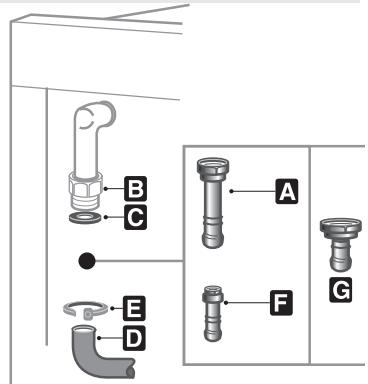
The hose connector G shown is not supplied with the appliance. Use only hose connectors compliant with the relevant regulations.
3 ADAPTATION TO DIFFERENT TYPES OF GAS

Before performing any cleaning or maintenance work, detach the appliance from the electrical socket.
The cooker hob is set for natural gas G20 (2H) at a pressure of 20 mbar for cookers with maxi oven, and for LPG G30/G31 (3+) at a pressure of 28/37 mbar for cookers with gas-bottle compartments. In the case of functioning with other types of gas the burner nozzles must be changed and the minimum flame adjusted on the gas taps. To change the nozzles, proceed as described below.
3.1 Replacement of nozzles on the hob
This operation requires no primary air regulation.
- Extract the grids and remove all the caps and flame-spreader crowns;
- unscrew the burner nozzles with a 7 mm socket wrench;
- replace the nozzles according to the type of gas to be used and the description in paragraph "3.2 / 3.3 Burner and nozzle characteristics table".
- Replace the burners in the correct position.

3.2 Burner and nozzle characteristics table (50-60 cm models)
| Burner | Rated heating capacity (kW) | LPG – G30/G31 28/37 mbar | ||||
| Nozzle diameter 1/100 mm | By-pass mm 1/100 | Reduced flowrate (W) | Flowrate g/h G30 | Flowrate g/h G31 | ||
| Auxiliary | 1.0 | 50 | 30 | 350 | 73 | 71 |
| Semi-rapid | 1.8 | 65 | 33 | 450 | 131 | 129 |
| Rapid (3) | 3.0 | 85 | 45 | 800 | 218 | 214 |
| Rapid (5) | 2.5 | 79 | 45 | 800 | 182 | 179 |
| Triple crown | 3.2 | 91 | 65 | 1500 | 233 | 229 |
| Oven | 3.2 | 87 | 48 | 850 | 233 | 229 |
| Burner | Rated heating capacity (kW) | NATURAL GAS – G20 20 mbar | |
| Nozzle diameter 1/100 mm | Reduced Flowrate (W) | ||
| Auxiliary | 1.0 | 72 | 350 |
| Semi-rapid | 1.8 | 97 | 450 |
| Rapid (3) | 3.0 | 115 | 800 |
| Rapid (5) | 2.5 | 108 | 800 |
| Triple crown | 3.5 | 133 | 1500 |
| Oven | 3.2 | 130 | 850 |
3.3 Burner and nozzle characteristics table (90 cm models)
| Burner | Rated heating capacity (kW) | LPG – G30/G31 28/37 mbar | ||||
| Nozzle diameter 1/100 mm | By-pass mm 1/100 | Reduced flowrate (W) | Flowrate g/h G30 | Flowrate g/h G31 | ||
| Auxiliary | 1 | 50 | 30 | 350 | 73 | 71 |
| Semi-rapid | 1.8 | 65 | 33 | 450 | 131 | 129 |
| Rapid | 3 | 85 | 45 | 800 | 218 | 214 |
| Triple crown | 3.2 | 91 | 65 | 1500 | 233 | 229 |
| Fish pan | 3.5 | 94 | 65 | 1500 | 255 | 250 |
| Oven | 1.9 | 68 | 45 | 800 | 138 | 136 |
| Maxi oven | 3.2 | 87 | 50 | 900 | 233 | 229 |
| Grill | 5.2 | 110 | 59 | 1300 | 378 | 372 |
| Maxi grill | 2.9 | 87 | // | // | 211 | 207 |
| Burner | Rated heating capacity (kW) | NATURAL GAS – G20 20 mbar | |
| Nozzle diameter 1/100 mm | Reduced Flowrate (W) | ||
| Auxiliary | 1 | 72 | 350 |
| Semi-rapid | 1.8 | 97 | 450 |
| Rapid | 3 | 115 | 800 |
| Triple crown (4) | 3.5 | 133 | 1500 |
| Triple crown (8) | 3.5 | 140 | 1500 |
| Fish pan | 1.9 | 94 | 800 |
| Oven | 3.2 | 130 | 850 |
| Maxi oven | 5.2 | 164 | 1200 |
| Grill | 2.9 | 130 | // |
| Maxi Grill | 4.0 | 150 | // |
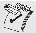
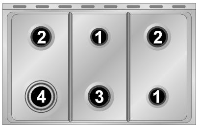
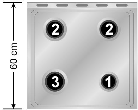
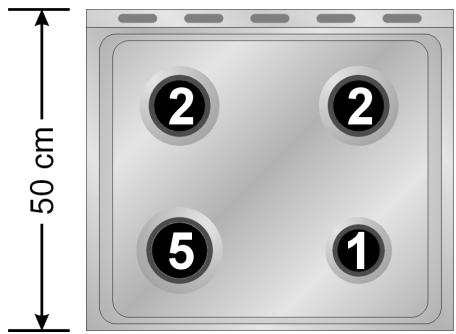
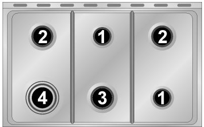
3.4 Arrangement of burners on cooking hob
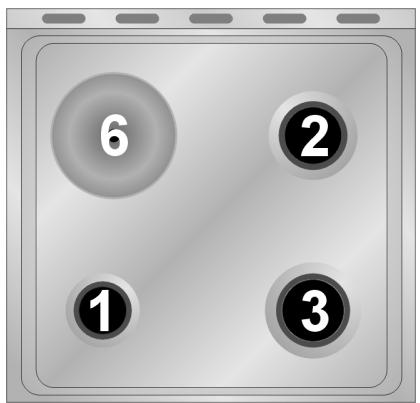
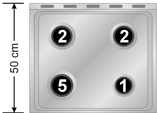
BURNERS
- Auxiliary
- Semi-rapid
- Rapid (60 X 60)
- Triple crown
- Rapid (60 X 50)
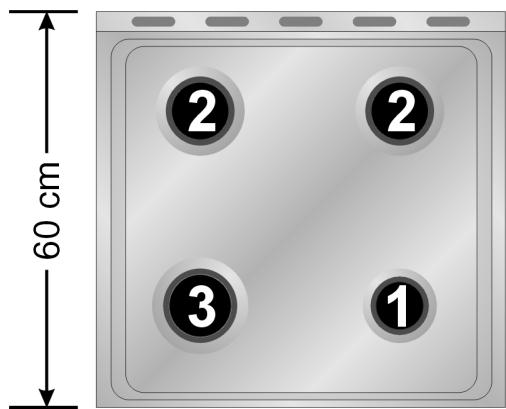
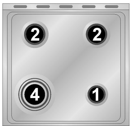
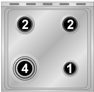
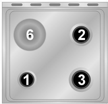
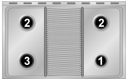
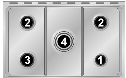
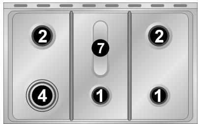
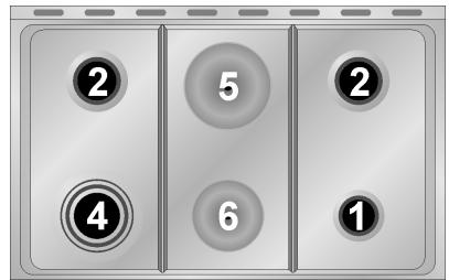
3.5 Arrangement of burners on cooking hob
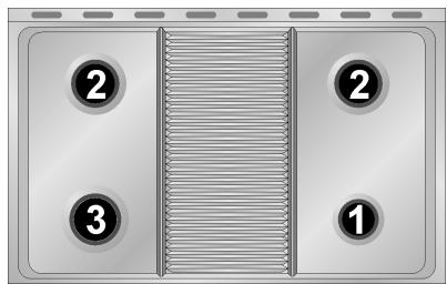
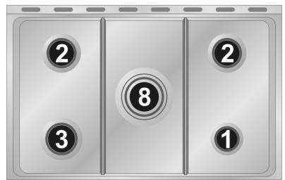
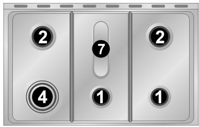
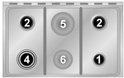
BURNERS
- Auxiliary
- Semi-rapid
- Rapid
- Triple crown
- Large electric hob (1500W)
- Small electric hob (1000W)
- Fish pan
- Triple crown
3.6 Adjustment of the oven burner (only for gas oven models)
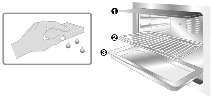
To adjust the oven burners follow the procedure described below from inside the oven:
- Open the oven door;
- Remove the oven dish and shelf.
- Lift up the oven floor and remove.
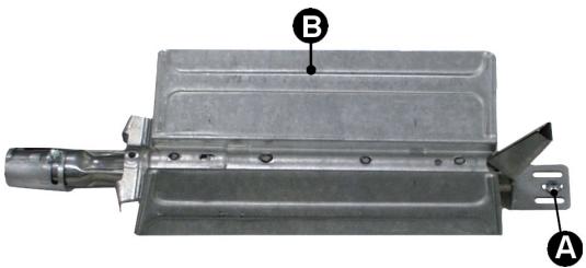
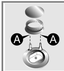
3.6.1 Replacement of the oven burner nozzle
- Loosen the fixing screws A on the oven burner.
- Push the burner B towards the right to get to the nozzle.
- Use a 13 socket wrench to change the nozzle, fitting the one for the type of gas to be used (see point "3.2/3.3 Table of burner and nozzle characteristics").
3.6.2 Regulation of the primary air on the oven burner
- Loosen the register screws "A" on the air regulation coupling.
- Turn the register coupling "B" to the position corresponding to the type of gas to be used according to the table below.
- Tighten the register screws and mount the seals.
- Once the operation is completed reassemble the burner correctly.
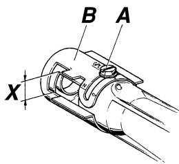
| NATURAL GAS | G30/G31 (GPL) 90cm Oven | G30/G31 (GPL) 60cm Oven | |
| X = | 5 mm | 10 mm | 10 mm |

NOTE: INSTALLATION IS ONLY TO BE CARRIED OUT BY A NATIONALLY CERTIFIED INSTALLER.
4 FINAL OPERATIONS
After replacing the nozzles, reposition the flame-spreader crowns, the burner caps and the grids.
Following adjustment to a gas other than the preset one, replace the gas adjustment label fixed to the appliance with the one corresponding to the new gas. This label is in the packet together with the nozzles.
4.1 Regulation of the hob burner minimum level for natural gas
Light the burner and turn it to the minimum position. Extract the gas tap knob and turn the adjustment screw at the side of the tap rod until the correct minimum flame is achieved.
Replace the knob and check burner flame stability: (rapidly turning the knob from maximum to minimum position, the flame should not go out). Repeat the operation on all the gas taps.
For models with valves, keep the knob at minimum level for about 1 minute to keep the flame lit and to activate the safety device.
4.2 Regulation of the hob burner minimum level for LPG
For regulating the minimum with LPG, the screw at the side of the tap rod must be turned clockwise all the way.
The bypass diameters for each individual burner are shown in paragraph "3.2/3.3 Burner and nozzle characteristics table". Once the regulation has been completed, replace the seal on the by-passes using paint or similar materials.
4.3 Regulation of the oven burner minimum level
The oven thermostat is equipped with a by-pass to regulate the minimum level, which is visible underneath the thermostat knob.
When the gas type is changed, the by-pass should be regulated as follows:
- Turn on the oven burner to maximum for 10/15 minutes with the door closed and without the floor. Turn the knob to the minimum temperature, remove the knob and regulate using a flat screwdriver.
- For LPG turn the by-pass screw clockwise as far as it will go. The by-pass diameter is shown in the paragraph "3.2/3.3 Burner and nozzle characteristics table".
- For natural gas, regulate the by-pass so that turning the thermostat knob from minimum to maximum the flame remains stable and constant. Once the regulation has been completed, replace the seal on the by-pass using paint or similar materials. Close the oven door and make sure that the burner stays on minimum.
4.4 Positioning and levelling of the appliance
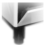
Having carried out the electricity and gas hook-up, level the appliance using the four adjustable legs. For best cooking the appliance must be perfectly level.
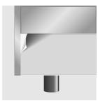
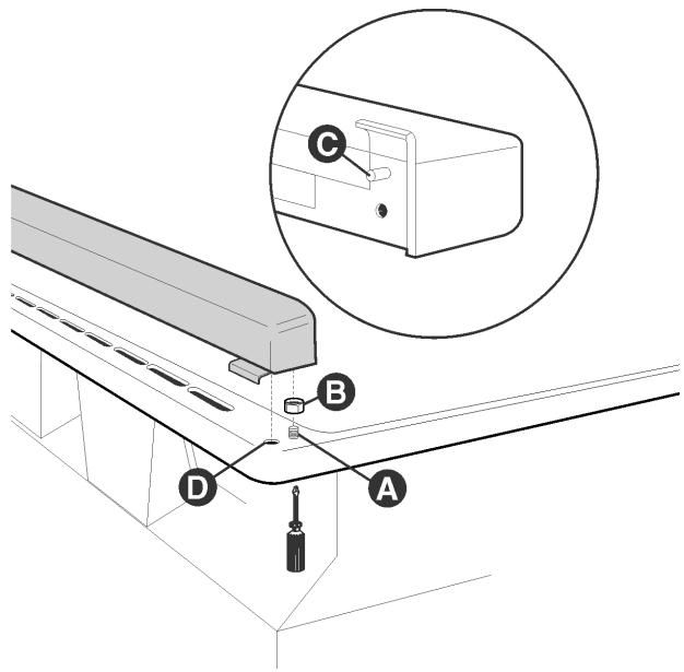
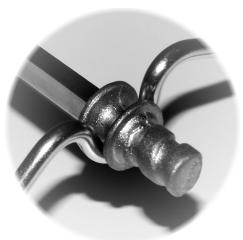
4.5 Mounting the rear top skirtboard (where applicable)
- Loosen nuts B.
- Position the skirt above the top, taking care to align pins C with holes D.
- Secure the skirt to the top by tightening screws A.
4.6 Positioning and levelling of the appliance
Having carried out the electricity and gas hook-up, level the appliance using the four adjustable legs. For best cooking the appliance must be perfectly level.
Depending on the model you have purchased, the foot height adjustment range may vary from 70 to 95mm and from 110 to 160mm . These heights refer to the distance between the highest point of the foot (fixed part) and the lowest point (movable part which rests on the floor).
5 DESCRIPTION OF FRONT PANEL CONTROLS
All the oven controls are grouped together on the front panel. The table below provides a description of the symbols used.

FRONT RIGHT BURNER
CENTRAL BURNER

BACK RIGHT BURNER
If the cooker is equipped with an electronic programmer, before using the oven make sure that the symbol appears on the display. See paragraph “8.1 Clock adjustment”.
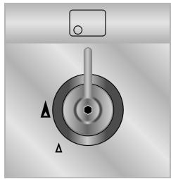
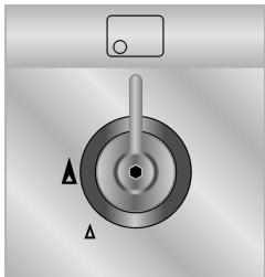
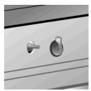
COOKING HOB BURNER COMMAND KNOB
The flame is lit by pressing the knob and turning it anticlockwise to minimum flame . To adjust the flame turn the knob between maximum () and minimum () . The burner goes out when the knob is returned to the position
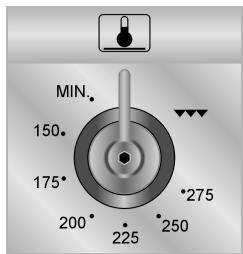
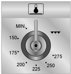
GAS OVEN THERMOSTAT KNOB (CERTAIN MODELS ONLY)
This knob is used to ignite the gas burner inside the oven. The cooking temperature is selected by turning the knob anticlockwise to the desired setting, between Min. and 275^ .
For information on how to ignite the gas oven, see point "7.3 Use of the gas oven".
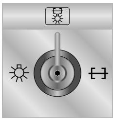
OVEN LIGHT / ROTISSEIRE / GRILL SELECTOR KNOB (CERTAIN MODELS ONLY)
This knob allows the user to activate the Grill / Rotisserie function or to switch on the light inside the oven to check the point reached in cooking the food.
CAUTION: IT IS NOT POSSIBLE TO OPERATE THE GAS OVEN AND THE GRILL / ROTISSERIE SIMULTANEOUSLY.

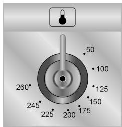
ELECTRIC OVEN THERMOSTAT KNOB (CERTAIN MODELS ONLY)
Selection of cooking temperature is carried out by turning the knob clockwise to the required temperature, between 50^ and 260^ .
The tell-tale light comes on to indicate that the oven is warming up. When it goes out it means that the required temperature has been reached. Regular flashing means that oven temperature is being constantly maintained at the programmed level.
STATIC ELECTRIC OVEN CONTROL KNOB (CERTAIN MODELS ONLY)
The various electric oven functions are suitable for different cooking modes. After selecting the function required, set the cooking temperature using the thermostat knob.
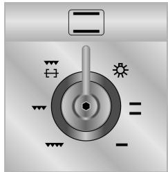

OVEN LIGHT

LARGE GRILL FUNCTION

STATIC OVEN FUNCTION

SMALL GRILL FUNCTION

LOWER RESISTANCE FUNCTION

SMALL GRILL FUNCTION + ROTISSERIE (IN THOSE MODELS WITH ROTISSERIE)
VENTILATED ELECTRIC OVEN FUNCTION KNOB (CERTAIN MODELS ONLY)
The various electric oven functions are suitable for different cooking modes. After selecting the function required, set the cooking temperature using the thermostat knob.
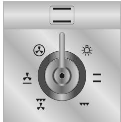

OVEN LIGHT

GRILL AND VENTILATOR FUNCTION

STATIC OVEN FUNCTION

LOWER RESISTANCE AND VENTILATOR FUNCTION

GRILL FUNCTION

VENTILATED OVEN FUNCTION
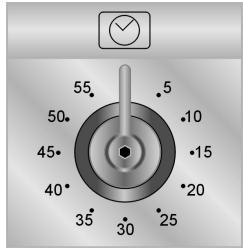
MINUTE COUNTER KNOB (CERTAIN MODELS ONLY)
Turn clockwise to wind up the alarm and set to the desired time.
Time is expressed in minutes (maximum 55 minutes).
Adjustment is continuous so that intermediate times between markings can also be set. Alarm activation at end of pre-set time does not turn off the oven (no end of cooking).
6 USE OF THE COOKING HOB
6.1 Lighting of the cooking hob burners

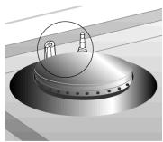
Before lighting the hob burners check that the flame caps are in the correct position and that their burner caps are in place, making sure that the holes A in the flame caps correspond to the spark plugs and thermocouples.
Before lighting the burners lift the glass cover; before lowering the cover, turn off all the burners and wait for them to cool down.

The optional grid ±bB is for use with "woks" (Chinese pans).
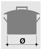
To prevent deterioration of the hob we have equipped the cooker with a raised pan stand C to be placed underneath pans more than 26 cm in diameter.
The supplied reduction rest C is also used for small pans.
The drawing next to each knob shows the corresponding burner. The appliance has an electronic lighting device. Simply press and turn the knob anticlockwise to the minimum flame symbol , until the ring is lit. If it does not light within the first 15 seconds, turn the knob to 0 and wait at least 60 seconds before trying to light the burner again. Hold the knob down for a few seconds to allow the thermocouples to heat up. The burner may go out when the knob is released: this is because the thermocouple has not been sufficiently heated. Repeat the operation holding down the knob for a little longer. This operation is not necessary for burners without thermocouples.

For models with thermocouples, if the burner should accidentally go out, a safety device will be activated which stops the gas flow even if the tap is open. In this case, turn the knob back to the off position and wait at least 60 seconds before trying to relight the burner.
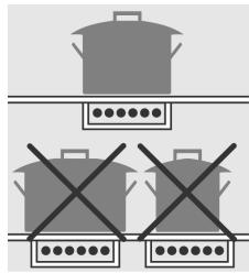
6.2 Practical advice for using the cooking hob burners
For better use of the burners and lower gas consumption, use covered containers that are proportional in size to the burner to prevent the flame from licking the sides (see paragraph "6.3/6.4 Diameter of containers"). When water reaches the boiling point, lower the flame so that it doesn't overflow. To avoid burns or damage to the hob, all recipients or griddle plates must be placed within the perimeter of the cooking hob. All containers have to have a flat and smooth bottom. When using fats or oils, be extremely careful that they don't overheat and catch fire.
If the flame accidentally goes out, turn off the control knob and wait at least 1 minute before trying to re-light the burner.
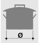
6.3 Diameter of containers (60 cm models)
BURNERS (60 X 60)
0 min. and max. (in cm.)
BURNERS (60 X 50)
- Auxiliary 12-14
- Semi-rapid 16-22
-
Rapid 18-24
-
Auxiliary 12-14
- Semi-rapid 16-24
3.Rapid 18-26 - Triple crown 18-26
6.4 Diameter of containers (90 cm models)
BURNERS
0 min. and max. (in cm.)
- Auxiliary 12-14
- Semi-rapid 16-22
- Rapid 18-26
- Triple crown 18-26
- Fish Burner Special oval-shaped vessels
6.5 Switching on the electric hob
6.5.1 Switching on the electric hobs
The cookers are equipped with hobs of different diameters. These are controlled by a switch and are turned on by turning the knob to the desired position. On the front panel above each knob a small drawing shows which hob corresponds to each knob. A yellow warning light lights up when the hob is switched on.
6.5.2 How to use the electric hobs
The rapid hobs offer the advantage of ultra-rapid cooking. Purely as an example the regulation table for the hobs is shown below.
| RAPID HOBS | HEAT INTENSITY | POSSIBLE COOKING |
| 0 | Off | - |
| 1 | Weak | To melt butter, chocolate, etc. To heat small amounts of liquid. |
| 2 | Soft | To heat larger amounts of liquid. |
| 3 | Slow | To defrost frozen food and prepare stews, cooking at or just below boiling point. |
| 4 | Medium | To cook food which has to reach boiling point, to roast delicate meat or fish. |
| 5 | Strong | For roasts, steaks and large boiled joints. |
| 6 | Very strong | To boil large amounts of water, to fry. |
WARNING
When switching on the hob for the first time, or if the hob has not been used for a long time, to remove any humidity from the insulating material it should be dried out by placing the hob on position 1 for 30 minutes.
To use correctly remember to:
- Switch the hob only after having placed the pan on it.
- Use flat and thick bottomed pans.
- Never use pans which are smaller than the hob.
- Dry the bottom of the pan before placing it on the hob.
- After use, to make sure that the surfaces are clean and long lasting, the electric hob must be treated with specific cleaning products which are available on the market. This necessary operation prevents oxidisation (rust formation).
- When cooking with flammable oils and fats, never leave the appliance.
- The hobs will stay hot for a long time after use: do not touch them or place any objects on them.
- Before switching on the electric hobs, lift up the glass cover on the cooker; before closing it, switch off the hobs and wait for them to cool down.
- If any dents appear in the hob surface, switch it off immediately and contact the nearest authorised servicing centre.
7 USE OF THE OVEN
For those models with electronic programmer, before using the oven make sure that the display shows the symbol
For those models with analogue clock and timer, place on the symbol
7.1Warnings and general advice
Using the oven and the grill for the first time, heat them to the maximum temperature (260°C for electric oven and 275°C for gas oven) for as long as it takes to burn off any production oil residues which could give a nasty flavour to the food. After a power cut, the oven display will flash intermittently and show 000. To adjust refer to paragraph "8 ELECTRONIC PROGRAMMER (ONLY ON EQUIPPED MODELS)".

The oven accessories which may come into contact with food are made from materials which conform to the standing directives.

WARNING: the gas oven is lit with the door open. The oven is equipped with a safety system which stops the burners being lit when the door is closed. If this is done wrongly, open the door and wait for a few moments before lighting once more.
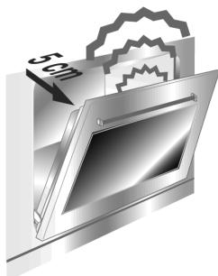

To prevent any steam in the oven creating problems, open the door in two stages: half open (5 cm approx.) for 4-5 seconds and then fully open. To access food, always leave the door open as short a time as possible to prevent the temperature in the oven from falling and ruining the food.
7.2 Cooling system
The oven is equipped with a cooling system which automatically comes on upon a few minutes after the oven has been turned on.
Fans cause a steady outflow of air from above the door which may continue for a brief period of time even after the oven has been turned off.
7.3 Use of the gas oven
7.3.1 Electronic spark lighting
Open the oven door completely, press the thermostat knob and turn it clockwise to max. temperature. The electronic spark lighting device will be enabled automatically. Once the oven is lit, hold the knob down for a few seconds to allow the thermocouple to heat up.
This device should not be enabled for more than 15 seconds; if after this time the burner has not come on, stop, fully open the oven door and try again after one minute.
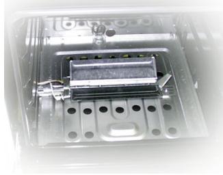
7.3.2 Manual lighting
Open the oven door completely and turn the thermostat knob. Place a lit match to the mouth of the flame pipe A in the centre of the oven floor and press the thermostat knob. Once the oven is lit, hold the knob down for a few seconds to allow the thermocouple to heat up and check that the oven is lit through the inspection hole B. Choose the cooking temperature by turning the knob clockwise to the desired temperature, between 50^ and 275^ .
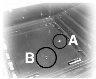

If the burner is accidentally switched off, turn the knob to the off position (●) and wait for one minute before lighting again.
7.4 Use of the electric grill
7.4.1 Using the grill in cookers with electric oven
For short cooking procedures, such as the final crisping of meat which is already cooked, select the static grill function and turn the thermostat knob to the maximum temperature. The fan grill function (certain models only) allows actual cooking procedures to be carried out, thanks to the fan function which ensures that the heat penetrates into the food. For this cooking mode, select the fan grill function and turn the thermostat knob to the ideal cooking temperature (never set at more than 200^ ).
7.4.2 Using the grill in gas cookers
To activate this function, the oven burner must first be switched off by turning the relative knob back to the position; the switch must then be turned to . CAUTION: IT IS NOT POSSIBLE TO OPERATE THE GAS OVEN AND THE GRILL / ROTISSERIE SIMULTANEOUSLY.
7.4.3 Operation of the grill + rotisserie
Both the static and the fan grill functions can be used for cooking in combination with the rotisserie. Fit the spit rod into the rotisserie bushing, select the or or fan grill function and turn the thermostat knob to the temperature of choice (never set at more than 200^ C).
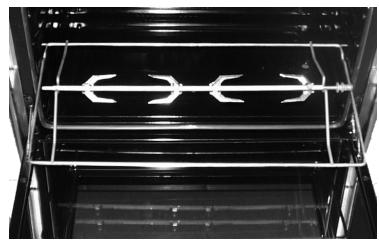
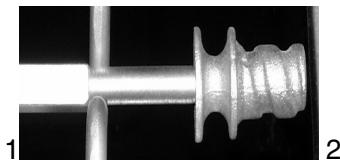
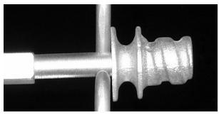
7.4.4 Using the rotisserie in cookers with maxi oven
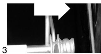
Fit the supporting frame onto the second runner up from the bottom so that the seat to take the rod projects outside the oven. Place the rod as shown in the diagram (1) and push the frame into the oven until the end of the rod reaches the hole in the rotisserie motor. Now push the rotisserie rod to the left until it reaches the position shown in the diagram (2). To activate this function, turn the switch to (+)
These operations must be carried out with the oven switched off and cold.
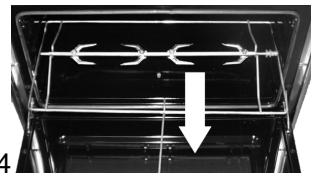
When cooking is over, use the tool provided to extract the rod from the hole (3) and remove the frame (4) to bring the rotisserie rod out of the oven cavity.
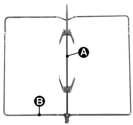
7.4.5 Using the rotisserie in cookers with standard ovens
Place the rotisserie frame "B" on the second runners up from the bottom and insert the rod "A" in the hole in the back of the oven.
How to use the grill

Once the grill is lit, the red warning light will come on. Leave the oven to heat up for five minutes before placing the food inside.
Food should be flavoured and basted with oil or melted butter before cooking. An oven dish should be used to contain the sauces.
The food should be placed on the oven shelf which is positioned on one of the guides supplied with the different ovens, following the instructions below:
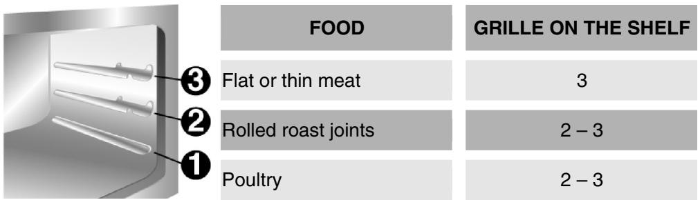
WARNING

- Cooking procedures in this mode must never last more than 60 minutes.
- In models with gas oven, the door must be half-open on the first catch during grilling and grill-rotisserie cooking.
- In models with electric oven, the door must be close during grilling and grill-rotisserie cooking.
- To avoid dangerous overheating when the oven or the grill is used, the glass cover must always be up. The electric grill and the gas oven cannot be used at the same time.
- During and after use the accessible parts of the oven may be very hot, and children must always be kept at a distance.
- During cooking with the rotisserie, one of the oven trays provided with the cooker should be placed in the bottom of the oven, inserting it on the bottom runners, in order to collect the grease and fats which may be formed.
- During cooking, do not cover the bottom of the oven with aluminium or tin foil and do not place pans or oven trays on it as this may damage the enamel coating. If you wish to use greaseproof paper, place it so that it will not interfere with the hot air circulation inside the oven.
- When using the oven, remove all unused baking sheets and shelves from the interior.
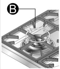
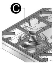
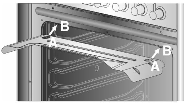
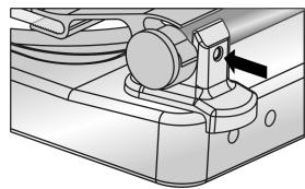
If your cooker is equipped with knob guard, when cooking using the grill or grill + rotisserie it must be fitted as shown here, fitting the slots "A" onto the pins "B" in the top of the oven.
7.5 Use of the gas grill
7.5.1 Manual lighting of the gas grill burner
Having opened the oven door, press the knob and turn it clockwise to the grill position, placing a lit match to the burner on the roof of the oven.
Once the burner is lit, hold the knob down for about 10 seconds. If the burner does not stay lit after this time, release the knob and wait for at least one minute before trying again. If the burner accidentally goes out, turn the knob to the off position (●) and wait at least one minute before lighting again.
7.5.2 Electric lighting of the gas grill burner
Having opened the oven door, press the knob and turn it clockwise to the grill position.
Once the burner is lit, hold the knob down for about 10 seconds. If the burner has not come on by this time, release the knob and wait for at least one minute before trying again. If the burner accidentally goes out, turn the knob to the off position (⊙) and wait at least one minute before lighting again.
During a power cut the burner can always be lit with a match.
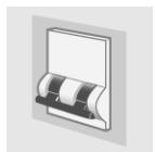
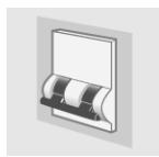
7.6 Storage compartment
A storage compartment, accessible by pulling on the top edge of the door, is located beneath the oven.
Never store flammable materials such as rags, paper or the like. The compartment is intended only for holding the metal accessories of the range.
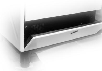

Never open the storage compartment when the oven is on and still hot. The temperature inside may be very high.
7.7 Gas bottle compartment (certain models only)
The gas bottle compartment can be reached through the side door and can also be used as an ordinary cupboard.
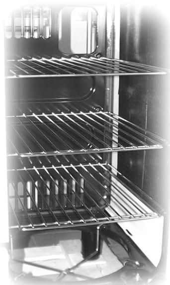
The 3 grilles shown in the diagram are not supplied with the appliance but can be purchased separately in any of the Authorised Servicing Centres.
8 ELECTRONIC PROGRAMMER (ONLY ON EQUIPPED MODELS)
LIST OF FUNCTIONS
| MINUTE-COUNTER KEY |
| COOKING TIME KEY |
| END-OF-COOKING KEY |
| DECREASE TIME KEY |
| INCREASE TIME KEY |
8.1 Clock adjustment
When using the oven for the first time, or after a power failure, the display flashes regularly and indicates 000. Press the keys 1 and at the same time the keys + or -: each single press changes the time by 1 minute either up or down.
Before setting the programmer activate the desired function and temperature.
8.2 Semiautomatic cooking
Use this setting for automatic oven switch-off at the end of cooking time.
By pressing key , the display lights up, showing 000 ; keep the key pressed and at the same time, press keys - or + to set the cooking time.
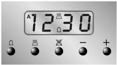
Release key to start the programmed cooking time count. The display will now show the right time together with symbols A and

8.3 Automatic cooking
Use this setting to automatically start and stop the oven.
By pressing key , the display lights up showing 000 ; keep the key pressed and at the same time, press keys - or + to set the cooking time.
By pressing key the sum of the right time + cooking time will appear; keep the key pressed and at the same time, press keys - or + to regulate the end of cooking time. Release key to start the programmed count and the display will show the right time together with symbols A and .
After set-up, to see the cooking time remaining, press the key ; to see the end of cooking time press the key . Set-up with incoherent values is logically prevented (e.g. the contrast between a cooking time and a longer period will not be accepted by the programmer).
8.4 End of cooking
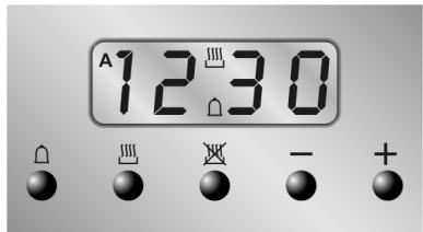
When cooking is over, the oven will automatically switch off and, at the same time, an intermittent alarm will sound. After switching off the alarm, the display will once again show the right time together with the symbol , indicating that the oven has returned to manual operation mode.
8.5 Minute Counter
The programmer can also be used as a simple minute counter. By pressing key , the display shows 000; keep the key pressed and at the same time press keys - or +. On releasing the key , programmed counting will begin and the display will show the current time and the symbol .

After set-up, to see the remaining time, press the key .
Use as a minute counter does not interrupt functioning of the oven at the end of the programmed time.
8.6 Adjusting alarm volume
The acoustic alarm has 3 different volume settings.
To change the setting, press the key at the end of the minute counter function with the acoustic alarm in operation.
8.7 Switching off the alarm
The alarm switches off automatically after seven minutes. They can be manually de-activated by pressing the keys and together. To switch off the appliance, rotate all the knobs to position 0.
8.8 Cancellation of set data
Once the programme has been set, keep the key of the function to be cancelled pressed, while at the same time 000 is reached by means of variation keys - or +. Time cancellation will be considered as end-of-cooking time by the programmer.
8.9 Changing the set data
The cooking data entered can be changed at any time by keeping the function key pressed and at the same time adjusting the keys - or +.
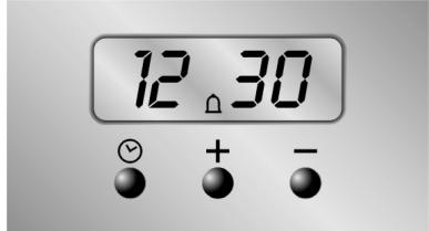
9 DIGITAL TIMER (CERTAIN MODELS ONLY)
This component allows an on-off beeper to be set to indicate the end of the cooking time. It is therefore just a timer, with no programming functions.
LIST OF FUNCTIONS

TIME-SETTING BUTTON

VALUE DECREASE BUTTON

VALUE INCREASE BUTTON
9.1.1 Setting the time
When the oven is used for the first time, or after a power blackout, the display flashes on and off at regular intervals showing 000 . Press the key and use the - or + keys to set the current time.
9.1.2 Setting the timer
To set the timer, press the + key and keep it pressed until the required number of minutes is shown. When the + key is released, after 5 seconds the countdown will start; once this finishes, an acoustic device will sound.
During the countdown the display will show the symbol; pressing the key displays the current time for 5 seconds.
9.1.3 Deactivating the acoustic device
The acoustic device stops sounding automatically after seven minutes. It can be deactivated in manual mode by pressing the + key.
9.1.4 Adjusting the volume of the acoustic device
The volume can be adjusted (3 settings) while it is in operation by pressing the key.
9.1.5 Modifying the data set
The timer data set can be modified at any moment by pressing the - or + keys.
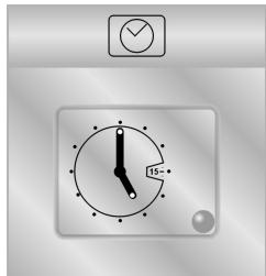
10 ANALOGUE CLOCK (ONLY ON EQUIPPED MODELS)
The mechanical timer is set by turning the knob clockwise.
The timer can be set from 0 to 55 minutes. At the end of the cooking time, an alarm signal will be heard: to stop the alarm turn the external part of the knob to position .
The clock is set by pulling the knob and turning it clockwise.
11 CLEANING AND MAINTENANCE
11.1 Cleaning stainless steel and enamelled versions
To maintain stainless steel in good condition it must be cleaned regularly after each use, once it has cooled down.
11.1.1 Ordinary Daily Cleaning
To clean and preserve the stainless steel surfaces, always use only specific products that do not contain abrasives or chlorine-based acids.
How to use: pour the product on a damp cloth and wipe the surface, rinse thoroughly and dry with a soft cloth or deerskin.
11.1.2 Food stains or residues
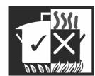
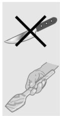
Do not use metallic sponges or sharp scrapers: they will damage the surface.
Use normal non-abrasive products for steel, and a wooden or plastic tool if necessary.
Rinse thoroughly and dry with a soft cloth or deerskin.
Do not allow residues of sugary foods (such as jam) to set inside the oven. If left to set for too long, they might damage the enamel lining of the oven.
11.2 Cleaning of cooking hob components
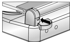
11.2.1 The glass cover
The lid can be taken off its hinges for easier cleaning.
1 - Open the lid;
2 - Undo the screws on the back of the two hinges (indicated by the arrows here) and lift it off.
If liquids are spilt onto the closed lid, wipe them off carefully with a cloth before opening it.

To replace the lid, fit it into the guides and screw in the hinge fixing screws with the lid open.
Take care not to touch the glass of the lid with hot pots and pans. The glass might crack due to the heat.
11.2.2 Grids
Remove the grids and clean them in warm water with a non-abrasive detergent, taking care to remove any incrustations. Replace them on the cooking hob.
Continuous contact of the grids with the flame can cause the paint near the hot areas to be altered.
This is completely natural and does not compromise the functionality of the component.
11.2.3 Burner caps and flame cap crowns
The caps and flame-spreader crowns are extractable to facilitate cleaning. Wash them in hot water with non-abrasive detergent, taking care to remove any incrustations, and wait until they are perfectly dry.

CAUTION: do not wash these components in a dishwasher.
The burners can be left to soak in hot water and detergent.
Replace the flame-spreader crowns, checking that they are positioned in their housing with their respective caps, taking care that flame-spreader holes A correspond to the spark plugs and the thermocouples.
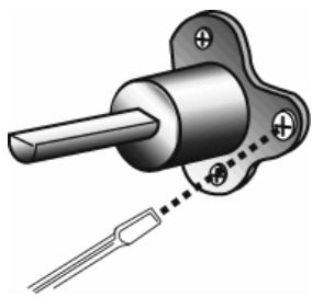
11.2.4 The spark plugs and thermocouples
To function properly the spark plugs and thermocouples must always be clean (on the models which are equipped with them). Check them regularly and clean with a damp cloth if necessary. Any dry residues can be removed with a toothpick or a needle.
11.3 Cleaning of oven

For best oven upkeep clean regularly after having allowed to cool. Take out all removable parts.
Clean the oven grill with hot water and non-abrasive detergent. Rinse and dry.
11.4 Door glass
The door glass should always be kept clean. Use absorbent kitchen paper to clean. In case of tough spots, clean with a damp sponge using regular detergent.
12 EXTRAORDINARY MAINTENANCE
The oven may require extraordinary maintenance or replacement of parts subject to wear such as seals, bulbs, and so on. The following instructions describe how to carry out these minor maintenance operations.
Before any intervention, disconnect the power supply of the device.
12.1 Lubrication of the taps and gas oven thermostat
In time the taps and gas oven thermostat may be difficult to turn or may be blocked. Clean them inside and replace the lubrication grease. This operation should be carried out by a specialised technician.
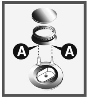
12.2 Replacement of light bulb
Remove cover A by twisting anticlockwise, replace bulb B with another similar bulb (25 W). Refit the cover A.
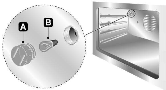
Only use oven bulbs (T 300°C).
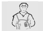
12.3 Removing the door
Raise levers B and hold the door on both sides with both hands near hinges A and. Lift up the door forming an angle of about 45^ and remove. To refit, slide the hinges A in the grooves, drop the door and release levers B.
12.4 Oven door seal
To permit thorough cleaning of the oven, the seal may be removed. Before removing the seal, take off the door as described above. Once the door has been taken off, lift the tabs at the corners as shown in the figure.
- INSTRUCTIONS FOR SAFE AND PROPER USE
- LOWER THE GLASS COVER SLOWLY AND BY HAND.
- INSTALLATION OF THE APPLIANCE
- Electrical connection
- Ventilation requirements
- Connecting to natural and LPG gas
- Connection to the gas bottle inside the compartment in the cooker (on some models only)
- Bottled gas connection (Only on some models)
- ADAPTATION TO DIFFERENT TYPES OF GAS
- Replacement of nozzles on the hob
- Arrangement of burners on cooking hob
- BURNERS
- Arrangement of burners on cooking hob
- Adjustment of the oven burner (only for gas oven models)
- Replacement of the oven burner nozzle
- Regulation of the primary air on the oven burner
- FINAL OPERATIONS
- Regulation of the hob burner minimum level for natural gas
- Regulation of the hob burner minimum level for LPG
- Regulation of the oven burner minimum level
- Positioning and levelling of the appliance
- Mounting the rear top skirtboard (where applicable)
- Positioning and levelling of the appliance
- DESCRIPTION OF FRONT PANEL CONTROLS
- COOKING HOB BURNER COMMAND KNOB
- GAS OVEN THERMOSTAT KNOB (CERTAIN MODELS ONLY)
- OVEN LIGHT / ROTISSEIRE / GRILL SELECTOR KNOB (CERTAIN MODELS ONLY)
- ELECTRIC OVEN THERMOSTAT KNOB (CERTAIN MODELS ONLY)
- STATIC ELECTRIC OVEN CONTROL KNOB (CERTAIN MODELS ONLY)
- VENTILATED ELECTRIC OVEN FUNCTION KNOB (CERTAIN MODELS ONLY)
- MINUTE COUNTER KNOB (CERTAIN MODELS ONLY)
- USE OF THE COOKING HOB
- Lighting of the cooking hob burners
- Practical advice for using the cooking hob burners
- Diameter of containers (60 cm models)
- Diameter of containers (90 cm models)
- Switching on the electric hob
- Switching on the electric hobs
- How to use the electric hobs
- WARNING
- USE OF THE OVEN
- 7.1Warnings and general advice
- Cooling system
- Use of the gas oven
- Electronic spark lighting
- Manual lighting
- Use of the electric grill
- Using the grill in cookers with electric oven
- Using the grill in gas cookers
- Operation of the grill + rotisserie
- Using the rotisserie in cookers with maxi oven
- Using the rotisserie in cookers with standard ovens
- How to use the grill
- Use of the gas grill
- Manual lighting of the gas grill burner
- Electric lighting of the gas grill burner
- Storage compartment
- Gas bottle compartment (certain models only)
- ELECTRONIC PROGRAMMER (ONLY ON EQUIPPED MODELS)
- LIST OF FUNCTIONS
- Clock adjustment
- Semiautomatic cooking
- Automatic cooking
- End of cooking
- Minute Counter
- Adjusting alarm volume
- Switching off the alarm
- Cancellation of set data
- Changing the set data
- DIGITAL TIMER (CERTAIN MODELS ONLY)
- Setting the time
- Setting the timer
- Deactivating the acoustic device
- Adjusting the volume of the acoustic device
- Modifying the data set
- ANALOGUE CLOCK (ONLY ON EQUIPPED MODELS)
- CLEANING AND MAINTENANCE
- Cleaning stainless steel and enamelled versions
- Ordinary Daily Cleaning
- Food stains or residues
- Cleaning of cooking hob components
- The glass cover
- Grids
- Burner caps and flame cap crowns
- The spark plugs and thermocouples
- Cleaning of oven
- Door glass
- EXTRAORDINARY MAINTENANCE
- Lubrication of the taps and gas oven thermostat
- Replacement of light bulb
- Removing the door
- Oven door seal
Brand : SMEG
Model : SCB92MN8
Category : Combined refrigerator