
GX6 - Wall or window fan APPLIED ENERGY - Free user manual and instructions
Find the device manual for free GX6 APPLIED ENERGY in PDF.
| Product Type | Wall or window fan |
| Brand | APPLIED ENERGY |
| Model | GX6 (variants: GX6, GXC6, GXC6T, GX6T, GX6HT, GX6HT2, GXS6, GX6 IP25) |
| Usage | Air extraction only |
| Power Supply | Fixed connection to mains; rated voltage to be checked on the device |
| Grounding | Mandatory |
| Protection | Protection fuse not exceeding 5 A; model GX6 IP25: IP25 ingress protection |
| Mounting | Wall, window, panel, roof |
| Hole Diameter | Window: 184 mm; Wall: 203 mm (with WK6 duct) |
| Required Tools | 6 mm screwdriver, 3 mm screwdriver, Pozidriv No. 1 and 2; for wall: drill, chisel, mortar |
| Controls | Remote switch or pull cord depending on model |
| Special Functions | Adjustable timer (2 to 20 min), adjustable humidistat (50% to 90% RH), trickle ventilation, two speeds (GX6HT2), backdraught shutter (GXS6) |
| Adjustments | Timer (T) and humidistat (H) adjustment screws; trickle ventilation catch |
| Maintenance | Clean impeller and grille with a damp cloth; do not use strong detergents or solvents |
| Maintenance Frequency | As needed; before cleaning, disconnect power and wait for complete stop of impeller |
| Supplied Accessories | Ladder bands (short for window, long for wall with kit), screws, caps, external grille |
| Optional Accessories | Wall kit WK6/300 (walls up to 300 mm) and WK6/450 (walls up to 450 mm) |
| Max Ambient Temperature | 50 °C |
| Certifications | Compliant with IEE regulations (GB); installation by qualified electrician |
| After-Sales Service | Technical support Xpelair (GB); for other countries, contact local retailer |
Frequently Asked Questions - GX6 APPLIED ENERGY
User questions about GX6 APPLIED ENERGY
0 question about this device. Answer the ones you know or ask your own.
Ask a new question about this device
Download the instructions for your Wall or window fan in PDF format for free! Find your manual GX6 - APPLIED ENERGY and take your electronic device back in hand. On this page are published all the documents necessary for the use of your device. GX6 by APPLIED ENERGY.
USER MANUAL GX6 APPLIED ENERGY
- Do read all the instruction leaflet before commencing installation.
- Do install each fan with a double pole isolating switch with a contact gap of 3mm in each pole.
- Do consult a glazier on the appropriate glass thickness for your size of window.
- Do make sure the mains electricity supply is switched off before attempting to make electrical connections or carry out any maintenance or cleaning.
- Don't install this fan in any window/panel which is less than 4mm thick.
Guarantee
Customers outside UK - see International below.
UK: The fan is guaranteed against defects for 3 years from the date of purchase.
- Please keep your purchase receipt.
- If you have any problems, contact Xpelair's Head Office at the address shown below.
Technical advice and service
Customers outside UK - see International below.
UK: Xpelair have a comprehensive range of services including:
- Free technical advice help-desk from Engineers on all aspects of ventilation.
- Free design service, quotations and site surveys.
- Service and maintenance contracts to suit all requirements.
Please ask for details:
- By telephone on Techline: +44(0) 8709 000430
- By fax on Techfax: +44(0) 8709 000530
At the address below
Head Office, UK Sales Office and Spares
Applied Energy Products Ltd, Morley Way, Peterborough, PE2 9JJ, England.
Telephone: +44 (0)1733 456789
Fax: +44 (0)1733 310606
Sales Hotline: +44 (0)8709 000420
http://www.xpelair.co.uk
For all your spares requirements (UK only):
Applied Energy Products Ltd, Parts Dept, Morley Way, Peterborough, PE2 9JB, England.
Telephone: +44(0) 08709 077077
Fax: +44(0) 08709 076076
International
- Guarantee: Contact your local distributor or Xpelair direct for details.
- Technical Advice and Service: Contact your local Xpelair distributor.
Installation and maintenance instructions
Retain for future reference
A
B
C
D
11
E1
E2
E3
F
G1
15 8
aJell 9
.10
a.11
.12
1.12
.()
.5jaiyaiyaiyaiyaiyaiyaiyaiyaiyaiyaiyaiyaiyaiyaiyaiyaiyaiyaiyaiyaiyaiyaiyaiyaiyaiyaiyaiyaiyaiyaiyaiyaiyaiyaiyaiyaiyaiyaiyaiyaiyaiyaiyaiyaiyaiyaiyaiyai
1
.1
.2001 2
a2 + a3 + a_4 = 10
a4
23 的一个点.
.2a 2gj 1zla .6
JJIJIJIJI.7
( x,y) = ( ab + c) ( a > 0) ( 2 + 3)
.()
()2d/0alldaalldgale
()
ygljla jgsg j
e cial i a bia aglal yolnla jgsy
y:50 yagglgjg jg.70
a()21/
( a + b) ( a^2 - ab + b^2) = a^3 + b^3
auiy iuii
Sgannnnn nn nnnnnnnnnnnnnnnnnnnnnnnnnnnnnnnnnnnnnnnnnnnnnnnnnnnnnnnnnnnnnnnnnnnnnnnnnnnnnnnnnnnnnnnnnnnnn
a3 = 12,a4 = 13,a_5 = 16
gjuaa oJz jia aclaw ylae jyogoljly
.(1a,jL)
0a()2d/1
( a + b) ( a^2 - 2ab + b^2) = a^3 + b^3
2.4.6.712.89.4
Jao aagaaagglglaallll alalalalalal
j1 = 0 j2 = 0 j_3 = 0
()21/
(a)
zLJIzJyIyIyIyIyIyIy
. Iolai aegia gillll aegyacg 12
eaaa aalaaaggl 2jao ae daaiaea
aagaae aee 1111111111111111
(6)
aJaa aag Jolai Jalj
aew w dalejly aalall aywll 2
1.25+1/25+1/25+1/25+1/25+1/25+1/25+1/25+1/25+1/25+1/25+1/25+1/25+1/25+1/25+1/25+1/25+1/25+1/25+1/25+1/25+1
jlaiai aaiial 2aogai i jz o
Jai jai jai jai jai jai jai jai jai
#
a 150
Laie jusillaljla jyai jia jia jia jia jia
aagbglgjginaa
J
Lc
juiuillai jgsjia jiuilci
a + b = 1 .
2j6
13] auiiaiaia 2ayuaiyaiayaiyai
.
sall aalaaaslllloaolay
.4c
zao jia Jiao you
gJ LgJLlue La,ayla Jcysi jyj
g 4c g 2 6
aaiy
2 2
j11111111111111
eollll jaii jaii jaii jaii jaii jaii
6 u 1 1 1 1 1 1 1 1 1 1 1
(6ω1ωs1
6u51
6 5
Jaa aae aae aee aee
aaii aai jai jai ai iai
Jauu aueaue Juaaui
6 5
JSeSseewdabzabwBgZg
aaii aai iiaai
.
山山山山
a.231 1
6w5
a a
aagjul juaa liuus jiaaii liq
Jus Jus
a>0.15dol0
16 5
S
aegbglgina 151 lgsagjia
.
aajjilge cuiuuiy jslolcuiuie 2
a aalaaalaaalaaal
Jz2x.() ()
J. J. J. J. J. J. J. J. J. J. J. J. J. J. J. J. J. J. J. J. J. J. J. J. J. J. J. J. J. J. J. J. J. J. J. J. J. J. J. J. J. J. J. J. J. J. J. J. J. J. J.
a
4
LgSsAsaAslll 1
aJUJnJxJxJxJxJxJxJxJx
2015年全国春季学业水平考试卷15
.
a 16
.
a23j1 1ab2e jil, jil
JSLJLJLJLJLJLJLJLJLJLJL
( x + 1) ( y - 1) = 0
131(y0g)(y)g0s1g2a 6
a#yol allaoj e jil. jol oJou Jull
Jusla Jsa aabawg yjSll jzj 1
2019 JNJ 1000511111
.aaell 2j.aaell aabw gaoell jSLI
Jz1s1 120000000000000000000000000000000000000
- 1234567890
aui jie cui iui 80 ga ie aoi cei .8
aallll aallll alll lalll
21 = 2
1.25 1.25 1.25 1.25 1.25
- 1.2.3.4.5.6.7.8.9
LwLgLoaog a2g 1gS1.10
a^3 + 3a^2 = 8b^3 + 4
C
a
auiyglj1 1xuoggl 1xu
aaii 1
1/6w/6 1
6w1wS1g/66wwS1g
6 6 1
2gJ 1
1 1 1 1 1 1 1 1 1 1 1 1 1 1 1 1 1 1 1 1 1 1
()
.
jolal jaiy 2jll aiil ay
jgl jz jy jz jz jz jz jz jz jz jz jz jz jz jz jz jz jz jz jz jz jz jz jz jz jz jz jz jz jz jz jz jz jz jz jz jz jz jz
a 1000
- gaiy 25,111
15
aagglg aagaaal gaaadall
Jnnnnaa Jannnnn nn nnnn nn nnnnnnnnnnnnnnnnnnnnnnnnnnnnnnnnnnnnnnnnnnnnnnnnnnnnnnnnnnnnnnnnnnnnnnnnnnnnnnnnnnnnnnnnnnnnnnn
45g()Jg
.450/6 45 300/6
Lagoo 2
.1511 1
a a a a a a a a a a a a a a a
()
a. 2 a. 3 a. 4
.
J 12
aalall 2. aalall alawy ayalld ySL
1211111111111111111 3
.
Jgjg jgjjg jgjjg 4
5
aJUJJnJzJg
g jil glll lal lal 1
jol jol jol jol jol
Cucitil gbi Jaoiwi ciis 1
1
aiee aaiagia aaii 2aii
J
Jauy Jauy gai jgai n 2a125 u95 i j
a 1
- paaai juiuui uuaauii
Jaae Lj
Jaaa aiao 1yagoloo jai j
jai jai jai jai jai lao Lai .aia aia
aJd jJl Jaiy 151
50 2
12
j0000()
15g 15g
aalaa aaii
a10 10
3
j_4 = 12 · ( 5 - 3) ^2 · 34 · 34 · 34 · 34 · 34 · 34 · 34 · 34 · 34 · 34 · 32
2ggljg 1g jg 4g g
yjg jy gai jai jai jay
1ggtj 2ggtj
ggtg 150
1.2aJyGnBjUoai 2gRjUgSi Looic gRjU
y
glllglalglgglgagpuey
Jooaiei oohjai 10
14.2511 2020
auii 12uaiuiuiuiuiuiuiuie 2015 ole y
- 1,1 , 1,1 , 1,1 , 1,1 , 1,1 , 1,1 , 1,1 , 1,1 , 1,1 , 1,1 , 1,1 , 1,1 , 1,1
alga 2gag Jaoa 1 gai 2 aay pluuiui iic
y
auiiLi) .aiai Cioiaai Li jis aizj
yus!e jgo aao Jno gaoaiao 1
( x + 1) ( y - 1) = 0
a#
yJSSLgssj ySsIglaI pIgI g
gagdglgdaaeeey
.
135
jL2a2g3o dLw1 g 1000000000000000000000000000000
la jie ly
.
yie 2gga aiai (caua) jra jna 5.2
.0yLaloljS: jll aaiall 1
j1. 8
pale 3 slys ycly clia, pala 6 y5ycly clia
- p 个点 1 个点, C4^1 · C4^2 · C4^3 · C4^4 · C_4^5 (2) sk sk
Jgss 15, dIaI gIe IgSsIJI 15
:
25LwJgSsIg.0aIg 1
jz jll jll j 4 j
jill pseo jolc
| L1| = | L2| = | L_3|
i(a)j)aajgaaag()c
( 1,3,32,0) .( 1,5)
.(ojialluiuog)g jzoo
()300/64(c)
300 aLi Li Lai Lai Jn Jn Jn Jn Jn Jn Jn
()450/64s山
(18) plo 450
1 Ldall Jzss! 3 zlll (JzJy) dLda4
aalss aagaae aegaae aee
(pa38×8paJ-gsallgall
2a+1
Jssao glai jglc gia
JbI/1JJIaJUaJpa145 aJc Jbc
.(aJj)
6ωS1g,6ωωS1g,(25g),6ωS1g,6ωS1g
2j36u|g j36u|g 6wS
6w1w51
Lg 1
- gao zai huo lao duan jiu: 2. ao gai liang yu zai qu
6wS1
Jus
( xt^2 + x) x = 0
a
6
a
aJg aJy J
4
16 5
aogolgaiia/la12
a
2ωjωj/6ωs
.
- a + b = 13 _____②
.
.
601/051
.
.
jLg 1
.
.
(25)
.
.3aJgacjwJia
.
JolallaoTo
yJy jy dLa
25 pao 3 Jluol o ggs j g aal jie c liia
()
20gj1c5j
aaii 1
a0g21 1c 1y1y1y1 y1y1 y1y1
11111111111111111
1.45
jgljgljgljgljgljglj
y
Jagoa
LwoggUgUuuaa1 a5 gaggu
a(1) 1
)gJgatglalalalalalal
(1)
0000j j 1j 1j 1j 1j 1j 1j
jie jie jie jie jie jie jie jie jie jie jie jie jie jie jie jie jie jie jie jie jie jie jie jie jie jie jie jie jie jie
PLEASE LEAVE THIS LEAFLET WITH THE FAN, FOR THE BENEFIT OF THE USER.
Installing the fan
This appliance is intended for connection to fixed wiring.
Check that the electrical rating shown on the appliance matches the mains supply.
WARNING: THIS APPLIANCE MUST BE EARTHED.
All installations must be supervised by a qualified electrician.
Installation and wiring must conform to current IEE regulations (UK), local or appropriate regulations (other countries).
If you have any queries before installing these products or after they have been installed, call the
Xpelair Technical Hotline +44 08709 000430. Our engineers are there to help you during normal office hours (UK only) and may be faxed at all other times +44 08709 000530.
Customers outside the UK please contact your local Xpelair distributor, details of which are available from the UK office.
Description
The GX6 models have the following features:
- Window / wall / panel / roof mounting options.
GX6
For remote switch operation.
- Single speed extract operation.
- Trickle ventilation setting.
GXC6
- Integral pull cord operation.
- Single speed extract operation.
- Trickle ventilation setting.
GXC6T
- Integral pull cord operation.
- Integral timer facility.
- Single speed extract operation.
- Trickle ventilation setting.
GX6T
- For remote switch operation.
- Integral timer facility.
- Single speed operation.
- Trickle ventilation setting.
GX6HT
For remote switch operation.
- Integral humidistat / timer facility.
- Single speed operation.
- Trickle ventilation setting.
GX6HT2
For remote switch operation.
- Integral pull cord operation.
- Integral humidistat / timer facility.
- Two speed operation.
- Trickle ventilation setting.
GXS6
- Remote switch operation.
- Single speed extract operation.
- Solenoid operated back draught shutters, for instant opening and closing.
- Trickle ventilation setting.
GX6 (IP25)
For remote switch operation.
- Single speed extract operation.
- Trickle ventilation setting
IP25 ingress protection.
What the installer will need
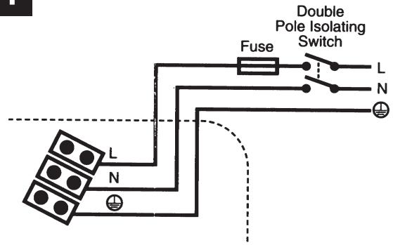
A means for disconnection in all poles must be provided in the fixed wiring in accordance with the wiring rules.
- If metal switch boxes are used, earthing regulations must be followed.
The GX6, GXC6, GXC6T and GXS6 require suitably rated 3-core cable (see "Installing switches and cables" section).
The GX6 (IP25) require suitably rated circular 3-core cable with a diameter not less than 5.5mm (see "Installing switches and cables" section).
The GX6T, GX6HT and GX6HT2 require suitably rated 4 or 5 core cable (see "Installing switches and cables" section).
The GX6T, GX6HT and GX6HT2 requires a wall or ceiling mounted "on /off" switch with built-in indicator light. For external boost/triggering, two switches are required.
- 6mm blade large screwdriver, 3mm blade electrician's screwdriver and No.1 & 2 Pozidriv screwdrivers.
If window mounting the fan, you will also need:
A single glazed window with a minimum glass thickness of 4mm or a double glazed unit with a pre-prepared sealed hole.
If wall mounting the fan, you will also need:
- Masonry drill, hammer & chisel (or core drill equipment, if available).
- Mortar (to make good the hole).
- Wall kit WK6/300 (available from Xpelair) for walls up to 300mm (12") thick or WK6/450 (available from
Xpelair) for walls up to 450mm (18") thick.
- 4 mounting fasteners (use fasteners suitable for wall type. Recommended screw size for standard brick - No.8 x 38mm Pan Head).
Where to locate the fan
- Locate it as high as possible.
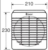
- At least 145mm from edge of the wall/ window frame to the hole centre (see Fig. A.).
- As far as possible from and opposite to the main source of air replacement to ensure airflow across the room (eg, Opposite an internal doorway).
- Near the source of steam or odours.
- Not where ambient temperatures are likely to exceed 50 degrees C.
If installed in a kitchen, fans must not be mounted immediately above a cooker hob or eye level grill.
If installing in a room containing a fuel burning device, which has a non balanced flue, it is the installers responsibility to ensure that there is enough replacement air to prevent fumes being drawn down the flue when the fan is operating up to maximum extract. Refer to Building Regulations for specific requirements. Exhaust air must not be discharged into a flue used for exhausting fumes from appliances supplied with energy other than electric.
Requirements of all authorities concerned must be observed for exhaust air discharge and intake flow rates. - When intended for use in possible chemical corrosive atmospheres, consult our technical service department. (For overseas markets contact your local Xpelair Distributor).
This electrical product, if installed in a shower room or bathroom, must be situated so that it cannot be touched by persons making use of the bath or shower.
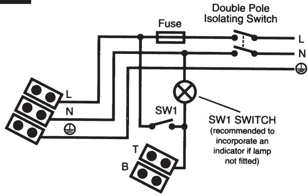
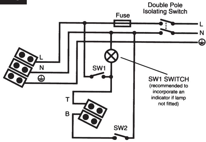
Installing the switches and cables
- Check that there are no buried pipes or cables (eg, electricity, gas, water) behind the switch location (in the wall or above the ceiling).
- Lay in the cable from the isolating switch to the fan location via the on/off switch (see Fig.E1), SW1 (see Fig.E2.) and external boost SW1 (see Fig.E3) if required.
- Lay in the cable from the isolating switch to the point of connection to the mains supply. WARNING: DO NOT MAKE ANY CONNECTIONS TO THE ELECTRICAL SUPPLY AT THIS STAGE
- Install the isolating switch and the on/off switch (see Fig.E1), SW1 (see Fig.E2) and external boost SW2 (see Fig.E3) if required.
- Make all connections within the isolating switch and the on/off switch if required.
Note: When installed in a bathroom all switches must be of a pull cord type and must be situated so that they cannot be touched by persons making use of the bath or shower.
GXS6
O E5aepiotnpac aeitoupyei e TnAoiKoTTn.
GX6 (IP25)
O E5aepiotnpac λeitoupyei με Tnλeiokntn.
Móvo yia ta GX6T / GXC6T / GX6HT kai GX6HT2
Pivkavete onoieodnote puoiieic, anopovotetov eepi npa teiaoc ao tvn kevtpiik nekpki napoxhi.
These models are permanently connected to the supply and operation is controlled by a remote switch.
They should be directly wired to the supply through an approved 10A wall mounted surface switch with at least 3mm clearance between contacts.
Preparing the hole
If working above ground level, appropriate safety precautions must be observed.
WARNING: EYE PROTECTION MUST BE WORN DURING ALL DRILLING AND CHISELLING OPERATIONS.
If installing in a wall
- Check there are no buried pipes or cables in the wall or obstructions on the outside (eg: electricity, gas, water).
- Ensure that the centre of the hole is located at least 145mm from the edges of the wall.
- Mark on the centre of the duct hole.
- Use this centre to draw a circle to suit the wall duct (203mm diameter for a WK6/300 or WK6/450).
If core drill equipment is available
5a.Use as directed by the core drill manufacturer.
If core drill equipment is not available
5b. Drill a centre hole right through the wall.
5. Cut the hole. Do not cut right through the wall (the recommended method is to drill a series of holes, close together, around the edge of the cutting line and remove the brick between the holes with a chisel).
7. Go outside and cut a hole in the outer wall, repeating the process described above.
8. Fit the ducting. Ensuring that the duct slopes down away from the fan to allow drainage of any incoming rain water to the outside.
9. Make good the hole. Allow for mortar to set before continuing with the installation.
If installing in a window
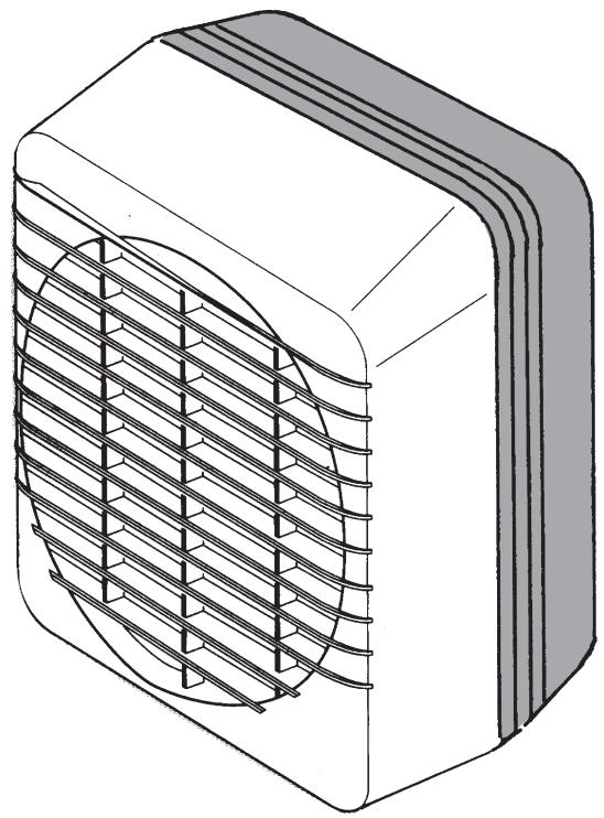
Obtain a ready cut pane with a correctly located hole 184mm diameter. (See Fig.A)
Preparing the Fan for installation
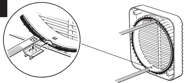
- For window mounting, use the two short ladder strips supplied with the fan.
For Wall mounting, use the longer strips supplied with the wall kit WK6/300 or WK6/450. - Secure the two ladder strips to the outer grille by positioning them over the hook moulding and snapping into position.
- Ensure after fitting the hook moulding that the gasket is in the correct position. (See Fig.B).
- Insert the two screw covers in the two fixing holes in the outer grille.
Mounting the fan in the hole Fig. C
If working above ground floor level, appropriate safety precautions must be observed.
Remove the Back Draught Shutter/Grille Assembly, by pressing the release catches located on the sides of the unit with a 6mm screwdriver or coin, whilst pulling the grille forward.
If fixing with ladder strips
- Hold up the outer grille to the outside of the wall or window so that the hole in the outer grille is aligned with the hole in the wall or window.
- If wiring from the rear, remove the fans terminal cover and rear entry knockout. Feed the cable through the top cable entry.
2b. If wiring from above, remove fans terminal cover and feed the cable through the top cable entry.
2c. For GX6 (IP25) only, wiring from above, remove fan's terminal cover. Pierce the cable entry grommet with a No. 1 screwdriver and feed the cable through the top cable entry via the grommet. DO NOT REMOVE THE GROMMET. - Hold the fan assembly to the inside of the wall or window and guide the ladder strips from the outer grille through the slots in the fan assembly.
- Insert the slotted screws into the pockets around the ladder strip slots.
- Tighten the screws carefully to make a good seal. Do not over tighten the screws.
- Trim the ladder strips back to the required length, if necessary remove any sharp edges.
If using screw fixings
- Hold the outer grille up to the outside of the wall so that the hole in the outer grille is aligned with the hole in the wall.
- Mark the positions of the fixing holes in the top right and bottom left corners.
- Drill the holes and insert anchor fixings to suit the wall.
- Screw the outer grille securely in place and fit screw caps in place. Do not over tighten screws.
- Insert the two screw covers in the two fixing holes in the outer grille.
6a. If wiring from the rear, remove the fans terminal cover, and rear entry knockout. Feed the cable through the knockout.
6b. If wiring from above, remove the fans terminal cover and feed the cable through the top cable entry.
6c. For GX6 (IP25) only, wiring from above, remove fan's terminal cover. Pierce the cable entry grommet with a no. 1 screwdriver and feed the cable through the top cable entry via the grommet. DO NOT REMOVE THE GROMMET. - Hold the fan assembly to the inside of the wall so that the spigot is inserted into the wall duct.
-
Mark the position of the two fixing holes in the top left and bottom right corners.
-
Remove the fan assembly, drill the holes and insert anchor fixings appropriate to the type of wall.
-
Reposition the cable and fan assembly as before, and screw securely in place. Do not over tighten screws.
Note: For particularly difficult installations, it is possible to secure the fan with a combination of screw and ladder strip fixings.
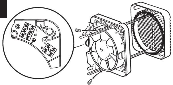
Wire the electrical connection
- Wire the switch cable into the terminal connections shown:
Fig.E1 for GX6/GXC6/GXC6T/ GXS6/GX6 (IP25).
Fig.E2 for GX6T / GX6HT.
Fig.E3 for GXHT2. - If the fan is wired from above, ensure the outer sheath of cable is retained in the labyrinth (see Fig.C).
- Refit and secure terminal cover.
- Refit the back draught shutter/grille assembly by sliding the grille back over the release catches, the catches will locate and secure the grille.
- Switch off the mains electricity supply and remove fuses.
- Connect the cable from the isolation switch to the electrical supply wiring.
- Replace the fuses and switch on the mains electrical supply. For fixed wiring circuits the protective fuse for the appliances must not exceed 5A.
Note: If using an external boost switch for the GX6HT2 (see Fig.E3), cut off the pull cord after ensuring that it is in the "off" position. This switch must be marked with suitable markings to indicate speed control.
Operating the Fan
These fans are single speed, except the GX6HT2 which is two speed, and all are non reversible (extract only).
The shutters have a time delay of up to 1 minute on opening and up to 3 minutes on closing. Activated by operation of the switch the delay ensures quiet operation (except GXC6 and GXS6 models).
For Australia Only:WARNING - Children should not play with the appliance. Young children and the infirm should be supervised.
GX6
The fan is operated by a remote switch.
GXC6
The fan is operated by an integral pull cord.
To switch on, pull down the cord and then release it.
Repeat to switch off.
GXC6T
The fan is operated by an integral pull cord.
To switch on, pull down the cord and then release it.
Repeat to switch off.
The integral timer provides an adjustable overrun period after the fan has been switched off.
The fan is operated by a remote switch.
The fan indicator light shows when it is switched on.
An integral timer provides an adjustable overrun period after the fan is switched off.
(see Fig.H).
3. Turn the adjuster clockwise to increase the timer overrun (see Fig.H).
4. Replace the back draught shutter/ grille assembly (see "Mounting the fan in the hole" section).
GX6HT
Condensation operation
The fan operates automatically if the relative humidity is above the set level.
The integral timer provides an adjustable overrun period after the relative humidity level has fallen.
Switched operation
A manual operation remote switch starts the fan. The fan indicator light shows when it is switched on.
The integral timer provides an adjustable overrun period after the fan has been switched off.
GX6HT2
Condensation operation
The fan operates automatically at low speed if the relative humidity rises above the set level.
The integral timer provides an adjustable overrun period after the fan has been switched off.
Boost operation
The integral pull cord switches the fan on to run at high speed. The fan indicator light shows when high speed has been selected.
- A remote switch may be used as an alternative to the pull cord. If this is used, cut off the pull cord, after ensuring that the pull cord switch is in the "off" position.
GXS6
This fan is operated by a remote switch.
GX6 (IP25)
This fan is operated by a remote switch.
GX6T / GXC6T / GX6HT and GX6HT2 only
Before making any adjustments, isolate the fan completely from the mains electricity supply.
Adjusting the timer overrun
The overrun timer is factory preset at approximately 20 minutes. The time is adjustable between approximately 2 to 20 minutes.
- Remove the back draught shutter/ grille assembly (see "Mounting the fan in the hole" section).
Adjusting the humidistat setting
The internal humidity sensor is factory set at approximately 70% . The level is adjustable between approximately 50% and 90% relative humidity.
Remove the back draught shutter/grille assembly (see "Mounting the fan in the hole" section).
Turn the adjuster marked "H" anticlockwise to decrease the relative humidity level of the room (see Fig. 1). Turn the adjuster clockwise to increase the relative humidity level of the room (see Fig.l).
Replace the back draught shutter/grille assembly (see "Mounting the fan in the hole" section).
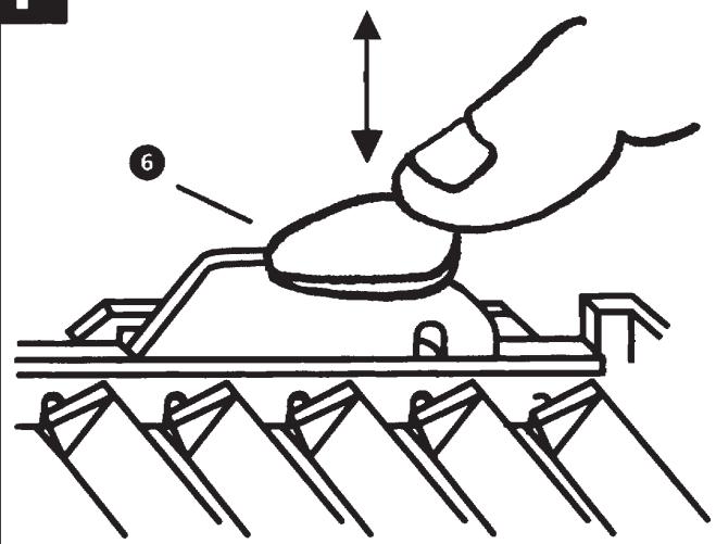
Trickle ventilation
Trickle ventilation is equivalent to that provided by an airbrick or similar device.
- Remove the back draught shutter/ grille assembly (see "Mounting the fan in the hole" section).
To allow trickle ventilation
- HOLD THE SHUTTER VANES FULLY OPEN.
- Push down firmly on the trickle vent catch until it clicks into position then release the shutter vanes. (See Fig.F item 6).
To fully close the shutters and stop any back draught
- Pull the trickle vent catch towards you until it clicks into position.
- Refit the back draught shutter/grille assembly, see "Mounting the fan in the hole" section, ensuring that the actuator lever is in the "fully down" position.
Maintenance
A QUALIFIED ELECTRICIAN MUST CARRY OUT ALL CLEANING.
NOTE: THE FAN WILL CONTINUE TO OPERATE WITH THE INNER GRILLE REMOVED HENCE IT MUST BE ISOLATED COMPLETELY FROM THE MAINS BEFORE ANY WORK IS CARRIED OUT.
electricity supply. Allow 3 minutes for the impeller to stop rotating and the powered shutter to close. (Cleaning on the GXC6 and GXS6 can begin once the impeller has stopped rotating).
-
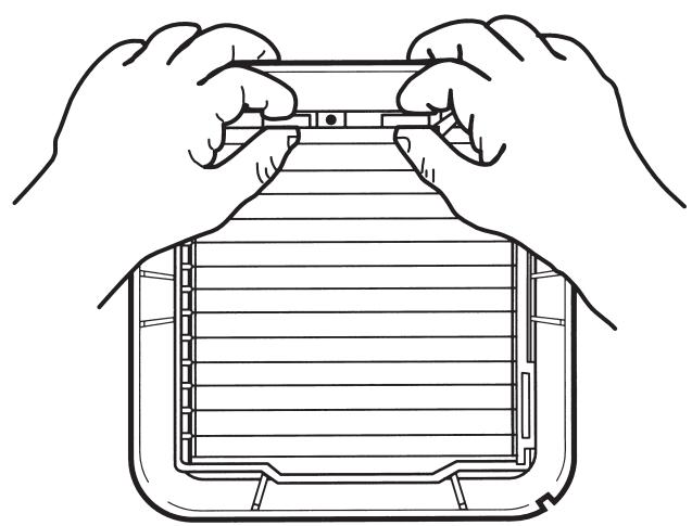
Remove the back draught shutter/ grille assembly by pressing the release catch located on the side of the unit with a 6mm screwdriver or coin, whilst pulling the grille forward. To remove the back draught shutter, lay face down and pull shutter forwards see Fig.G1 and Fig.G2.
-
To remove the impeller. Unscrew the central screw and remove it together with the washer. Place screw and washer to one side.
-
To clean the impeller, either wipe it with a damp, lint free cloth or wash it in warm soapy water. Thoroughly dry the impeller and refit. Replace the screw and washer ensuring that they are securely fitted.
-
Clean the back draught shutter/grille assembly and impeller in warm soapy water. Do not use strong detergents or chemical cleaners.
-
Thoroughly dry the back draught shutter/grille assembly and refit by sliding the grille back over the realise catches, the catches will locate in and secure the grille (see Fig.G3 and Fig.G4). For GXS6 MODEL: Ensure that the actuator lever is in the "fully down" position.
7. Do not immerse the fan in water or other liquids to clean any other parts of the fan.
Never use strong solvents to clean the fan.
Apart from cleaning, no other maintenance is required.
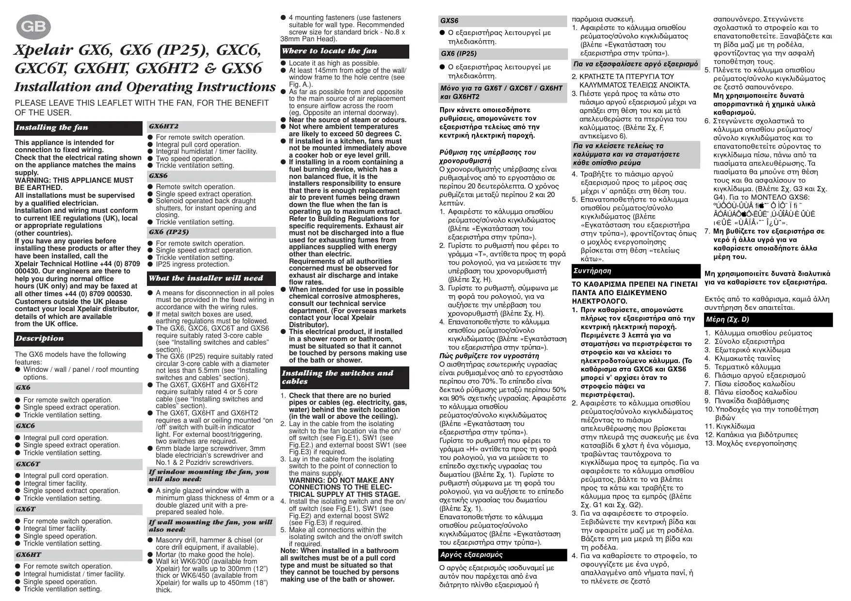
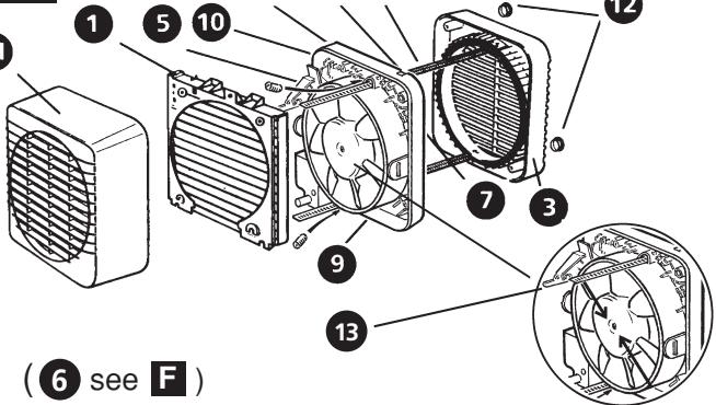
Components Fig. D
- Back draught shutter.
- Fan assembly.
- Outer grille
- Ladder strips
- Terminal cover
- Trickle vent catch
- Rear cable entry.
- Top cable entry.
- Rating plate.
- Lugs for screw mounting.
11.Grille. - Screw hole caps.
- Actuator lever (GXS6 model only).
IKAVONIOINTIK avavewan aepa yia va anoepyuayetai n apappooan aepiw ano tv kanvayoyo tov c Eaepiotnpac leitoupyei To eYiTo pUO Eaywn. ZoupuaueTeIE touc
Oikoδoikouc Kavoviaouc yia oukyekpiuevce anaitnncic,O eayouveoc aepac de npnteiv aantleuebpewteai kantvayyo tou xnpaiooteiit yia tnv eaywn apeiwi ao quakeec tou tropofootouvtai me evpeyie aanntoTov nkeptipno. npnteiv va epapuoztovai oaiatniac olwv Tuv evdoiaepoeuow apxov oxetika me Tnv eayawn aepa kai tou pbouc poanc Tou iayouevou aepa.
Otav npoopicietai yia xpnan e Tnivawcs Xnmukec oeiowtikec atmoopaicec, aoumuuethetaite To Tunjua Texviokc Eumnpetnonc Tnc taipeiac mac. (Tia tic ayopec Tou Eoioteipkou, aneuuveate Oto diavouea TxCpelair anv nepioxqac).
- Av ekataaTaeei oE vtouc n mavio, n naekpiki autn ooukeun npTei va bpiketai tonoetnev n e anueio nou va unmnpovv tv avyigouv ta npoogwnou xpnaiponoiou v tovtouc n to mnavio.
Eyataotaon Tov diaKoTov Kai Kaawiw
- Beaiaowite ot Dev unapovu Baaevoolnvek n kalwoia (n.x. Tou vepou, Tou ykaqou, Tou nekptiagou) niaw ano to anueio onou pbiakai o diakontc (stov Toiox npaw ano to taavi).
- Tono0eTnOte To kalwio ano tv anoovotkiDiaokntnWcTo anueio noupkiKetai O EaeipoiPac mEow to diaokntn on/off (BLeNE X .E1),tou SW1 (BleNE X .E2)kai nC eEwTeepiKnC evioxuaqsw1 (BLeNTe X .3),av anaiteita.
- TOnoTheTo Kaawio ano tv aoouovtiko diakottm wc to 0ia uovdeoc stynlEeptikn npoxh.
\PPOEI OIOH\SH:MHN KANETE KAMIA YN E\SH THN HAEKTIPIKH APOXH ^ AYTO TO TAIO.
Eykaataomate tov anoovotko diakokntto vok daikonnt on/off (BLe nE E1) to SW1 BLe nE E2) kai nV eGtwepiEvioxuON SW2 (BLe nE 3),av atraiteia.
5. Kävete Óeç TC uovdêaic μea o tov aiooVwtko diaköTTK kai tov diokontn on/off, av anatéitai
Klargjore viften for installing
WAARSCHUING: DIT APPARAAT MOET WORDEN GEAARD.