VISIONMOUNT UNDER CABINET MOUNT-VMUC1 - Under Cabinet Mount SANUS - Free user manual and instructions
Find the device manual for free VISIONMOUNT UNDER CABINET MOUNT-VMUC1 SANUS in PDF.

| Brand | SANUS |
| Model | VISIONMOUNT UNDER CABINET MOUNT-VMUC1 |
| Product Type | Under-cabinet TV mount |
| Screen Compatibility | Flat LCD screens up to 17 inches |
| Maximum Load Capacity | 6.8 kg |
| Material | Steel |
| Color | Black |
| Swivel (with stop) | ±35° |
| Swivel (without stop) | ±110° |
| Height Adjustment | Yes (by sliding) |
| Cable Management | Yes, with included cable clips |
| Required Tools | Phillips screwdriver, drill, 1/4 inch drill bit |
| Included Parts | Screen bracket, mounting plate, M4 bolts, T-nuts, spacers, cable clips, Allen key |
| Installation | Mount under a cabinet by drilling 3 holes |
| Safety | Do not use defective parts; call a qualified technician if in doubt |
| Maintenance | Clean with a soft, dry cloth |
| Repairability | Spare parts available from Sanus |
| Warranty | Consult the Sanus website for more information |
Frequently Asked Questions - VISIONMOUNT UNDER CABINET MOUNT-VMUC1 SANUS
User questions about VISIONMOUNT UNDER CABINET MOUNT-VMUC1 SANUS
0 question about this device. Answer the ones you know or ask your own.
Ask a new question about this device
Download the instructions for your Under Cabinet Mount in PDF format for free! Find your manual VISIONMOUNT UNDER CABINET MOUNT-VMUC1 - SANUS and take your electronic device back in hand. On this page are published all the documents necessary for the use of your device. VISIONMOUNT UNDER CABINET MOUNT-VMUC1 by SANUS.
USER MANUAL VISIONMOUNT UNDER CABINET MOUNT-VMUC1 SANUS
International Assembly Instructions for model VMUC1

SANUS SYSTEMS
Assembly Instructions for Model: VMUC1
Thank you for choosing a Sanus Systems Vision Mount under cabinet mount. The VMUC1 is designed to hold up to a 17 inch flat panel LCD weighing up to 15 lbs.
Safety Warning: If you do not understand these directions, or have any doubts about the safety of the installation, please call a qualified contractor or contact Sanus at 800.359.5520 or www.sanus.com. Check carefully to make sure that there are no missing or defective parts. Our customer service representatives can quickly assist you with installation questions and missing or damaged parts. Replacement parts for products purchased through authorized dealers will be shipped directly to you. Never use defective parts. Improper installation may cause damage or serious injury. Do not use this product for any purpose that is not explicitly specified by Sanus Systems. Sanus Systems can not be liable for damage or injury caused by incorrect mounting, incorrect assembly, or incorrect use. Please call Sanus Systems before returning products to the point of purchase.
Required Tools: Phillips screw driver, drill, 1/4 inch drill bit
Supplied Parts and Hardware: Some parts not shown as actual size*
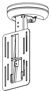
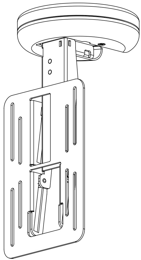
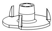
(1) Mount Assembly - a
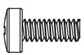
(4) M4 x 10 mm Bolt - d
(3) T - Nuts - b
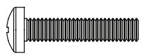
(4) M4 x 20 mm Bolt - e

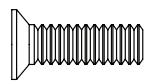
(3) 10 - 24 × 5 / 8 Bolt-c
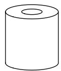
(4).5 inch Spacer - f
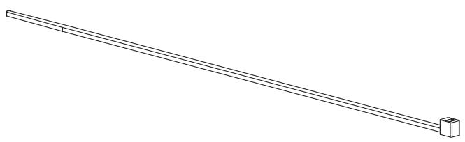
(4) Cable Tie - g
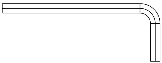
(1) Allen Key - h
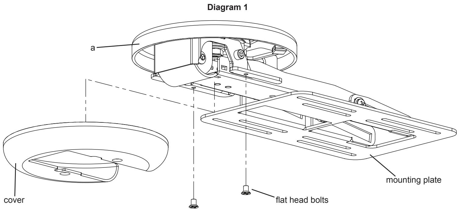
Step 1: Remove Cover
Using a Phillips screw driver loosen the two flat head bolts from the cover and slide it down and away from the mounting plate. See Diagram 1 for assistance. You will re-install the cover once cable management is complete.
Step 2: Prepare Mounting Surface
Use the base of the Mount Assembly (a) as a template to mark three holes in the cabinet in the desired location.
Drill three 1/4 inch holes at the marked locations.
See the dimensional drawing on the right for assistance.
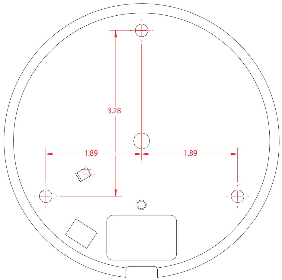
Dimensional Drawing
Step 3: Secure Mount Assembly to cabinet
Using the 10 - 24× 5 / 8 Bolts (c) and the T - Nuts (b) secure the Mount Assembly to the cabinet. See Diagram 3 for assistance. Note: Make sure the spikes on the T - Nuts is facing toward the cabinet.
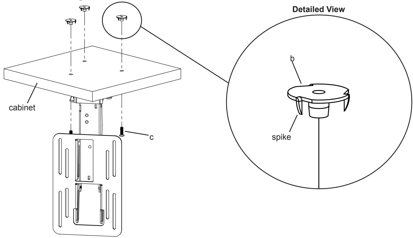
Diagram 3
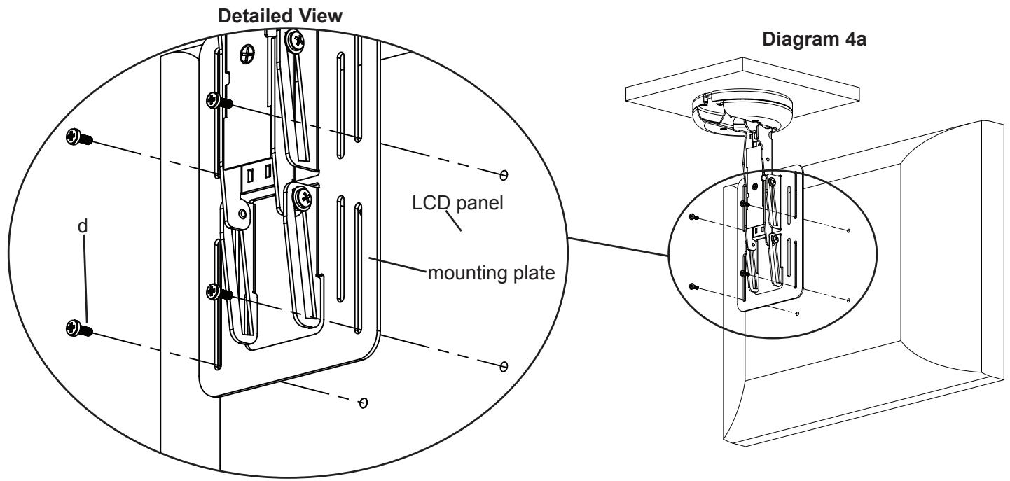
Step 4: Attach flat panel display to mounting plate
Make sure no power is supplied to the display before mounting the display!
Warning: Watch for pinch points. Do not put your fingers or cables between movable parts.
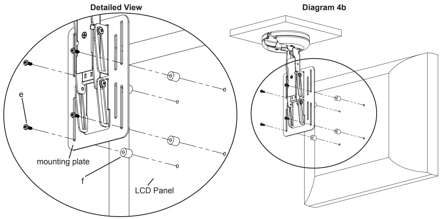
Once the Mount Assembly (a) is secured to the cabinet, align the appropriate slots in the mounting plate with the four mounting holes of your LCD display. Use either four M4 x 10 mm Bolts (d) or four M4 x 20 mm Bolts (e) with four .5 inch Spacers (f). Diagram 4a below shows the M4 x 10 mm Bolts being used. Diagram 4b on the next page shows the M4 x 20 mm Bolts with the .5 inch Spacers.
Step 4 (cont)
The .5 inch Spacers (f) should only be used if there is an obstruction or the hole pattern is physically recessed on the back of the LCD panel. See Diagram 4b for assistance.
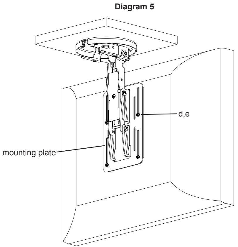
Step 5: Adjusting the screen height.
Using a Phillips screw driver, slightly loosen the Bolts (d,e) that secure the LCD panel to the mounting plate. Adjust the LCD panel to the desired height. Tighten the Bolts (d,e) to secure the LCD panel to the mounting plate. See Diagram 5 for assistance.
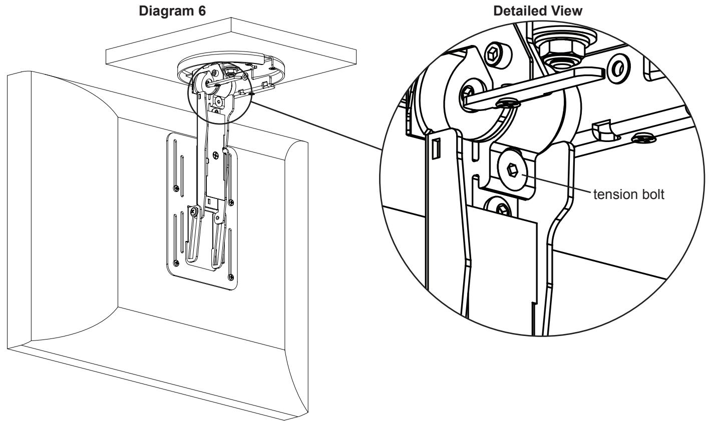
Step 6: Adjust tension of Mount Assembly
The tension of the Mount Assembly (a) can be adjusted by simply tightening or loosening the tension bolt labeled in Diagram 6 with the provided Allen Key (h).
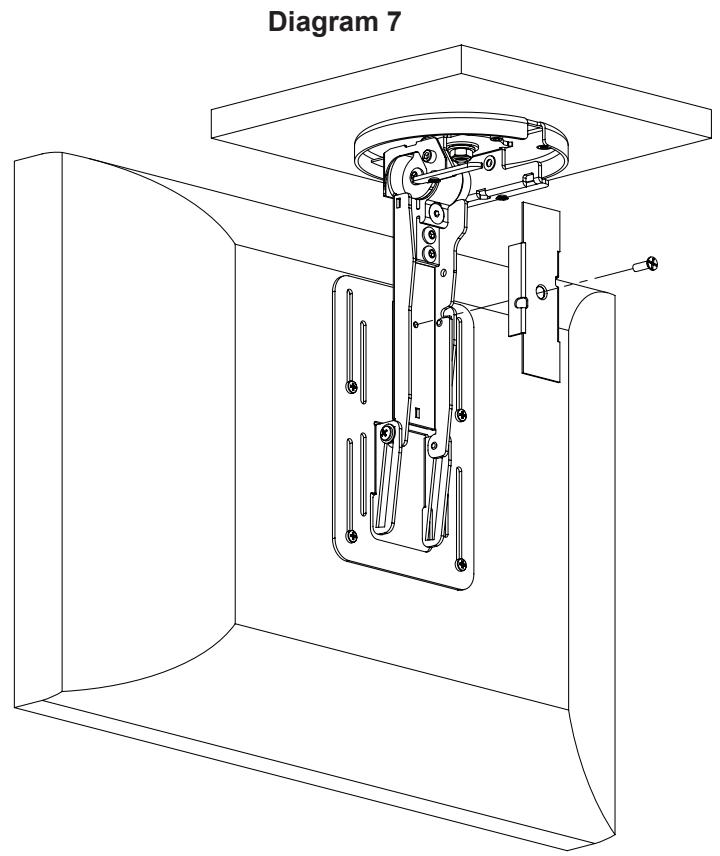
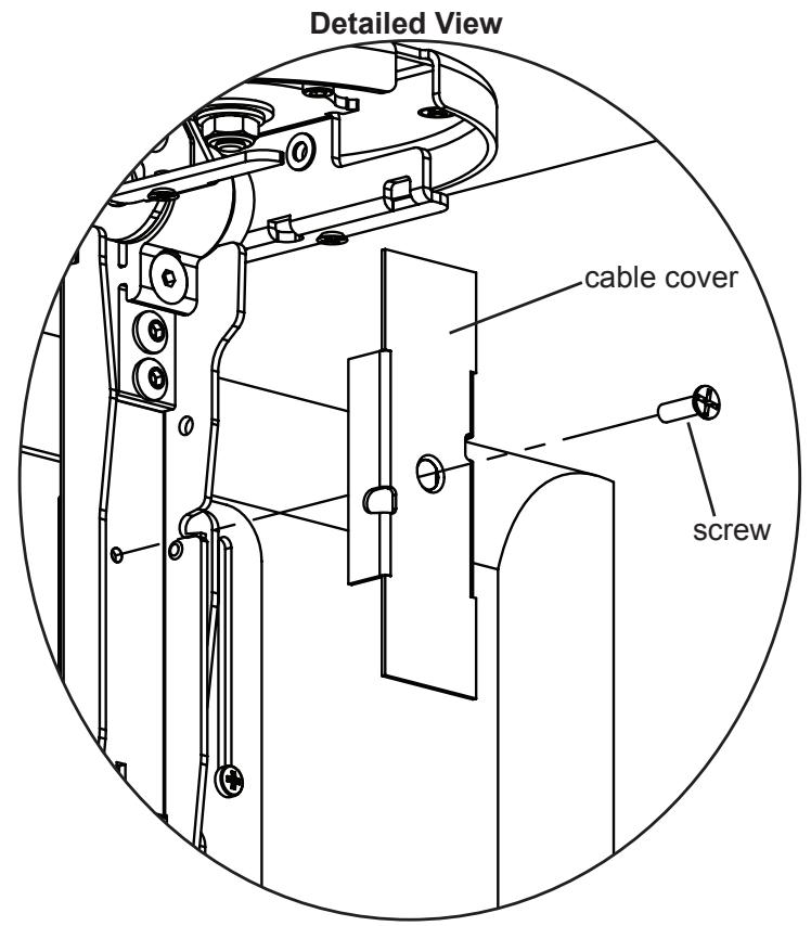
Step 7: Remove Cable Cover
Using a Phillips screw driver, loosen the screw in the center of the cable cover and remove cover. See Diagram 7 for assistance. Note: You will re-install the cable cover once cable management is completed.
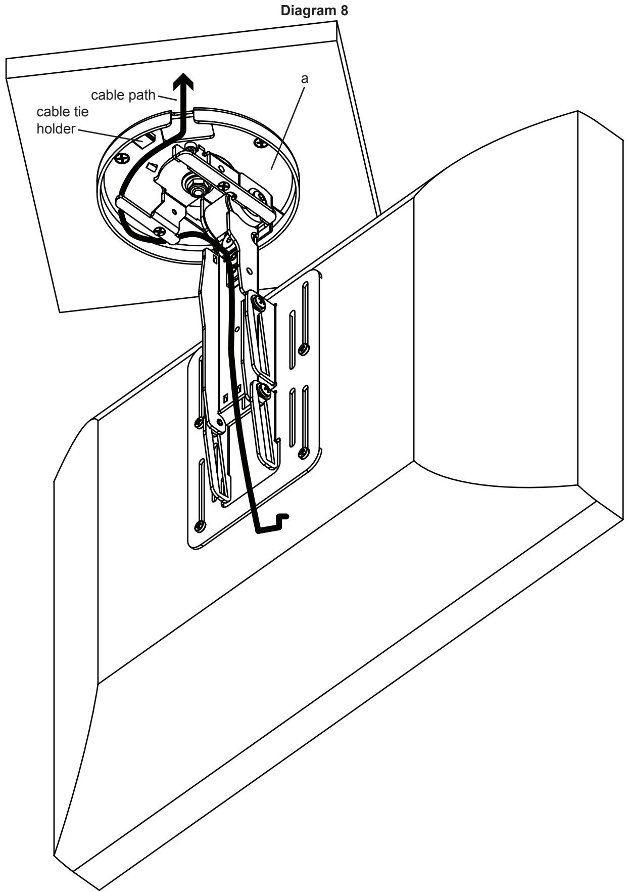
Step 8: Cable Management (±35° swivel)
Swivel the Mount Assembly (a) 35^ either left or right. You will run the cables in the opposite direction. You can attach the Cable Ties (g) in locations marked in Diagram 8 below.
Step 9: Remove Degree Stop
Using provided Allen Wrench (h), remove the 35 degree stop. See Diagram 9 for assistance.
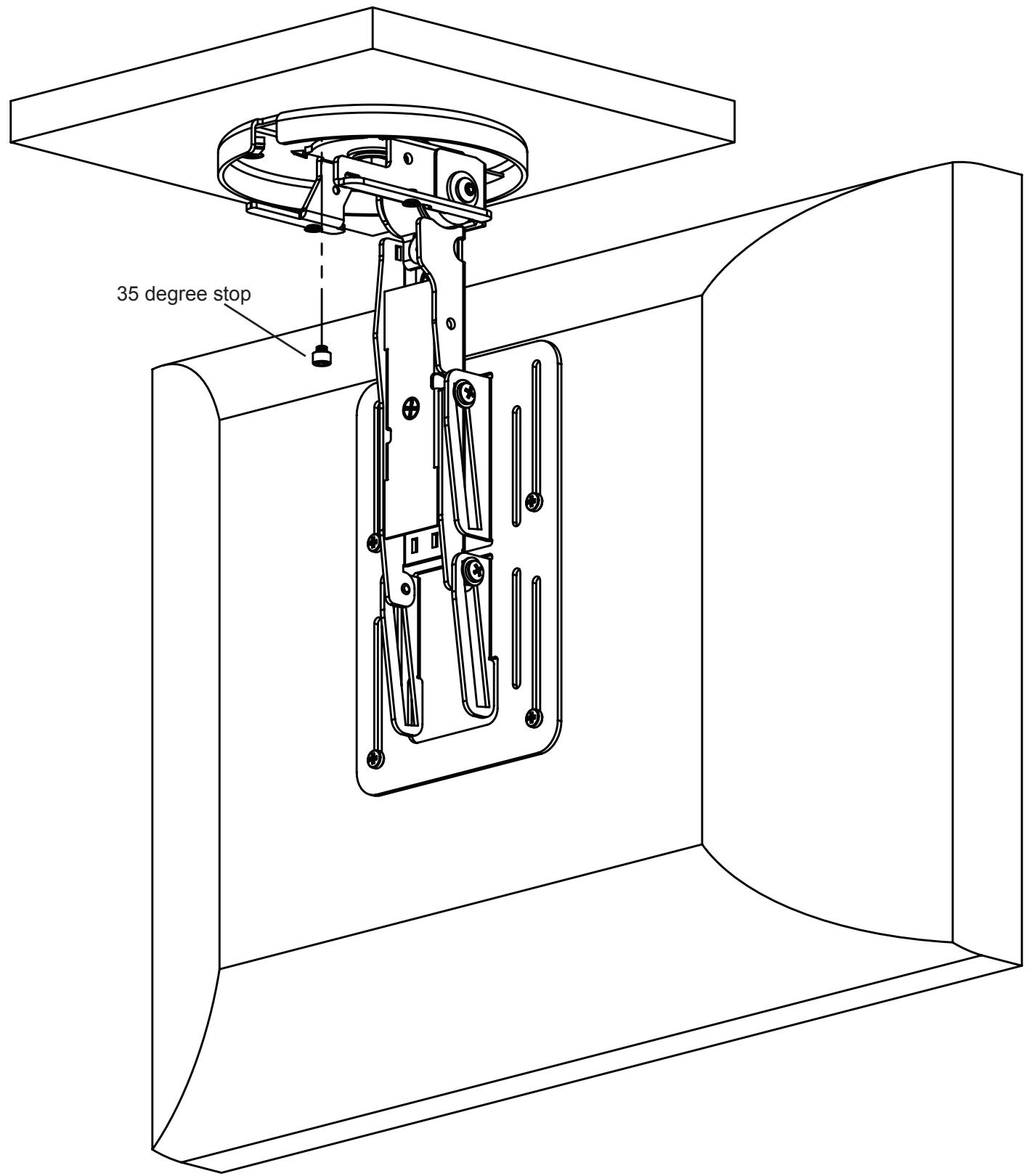
Diagram 9
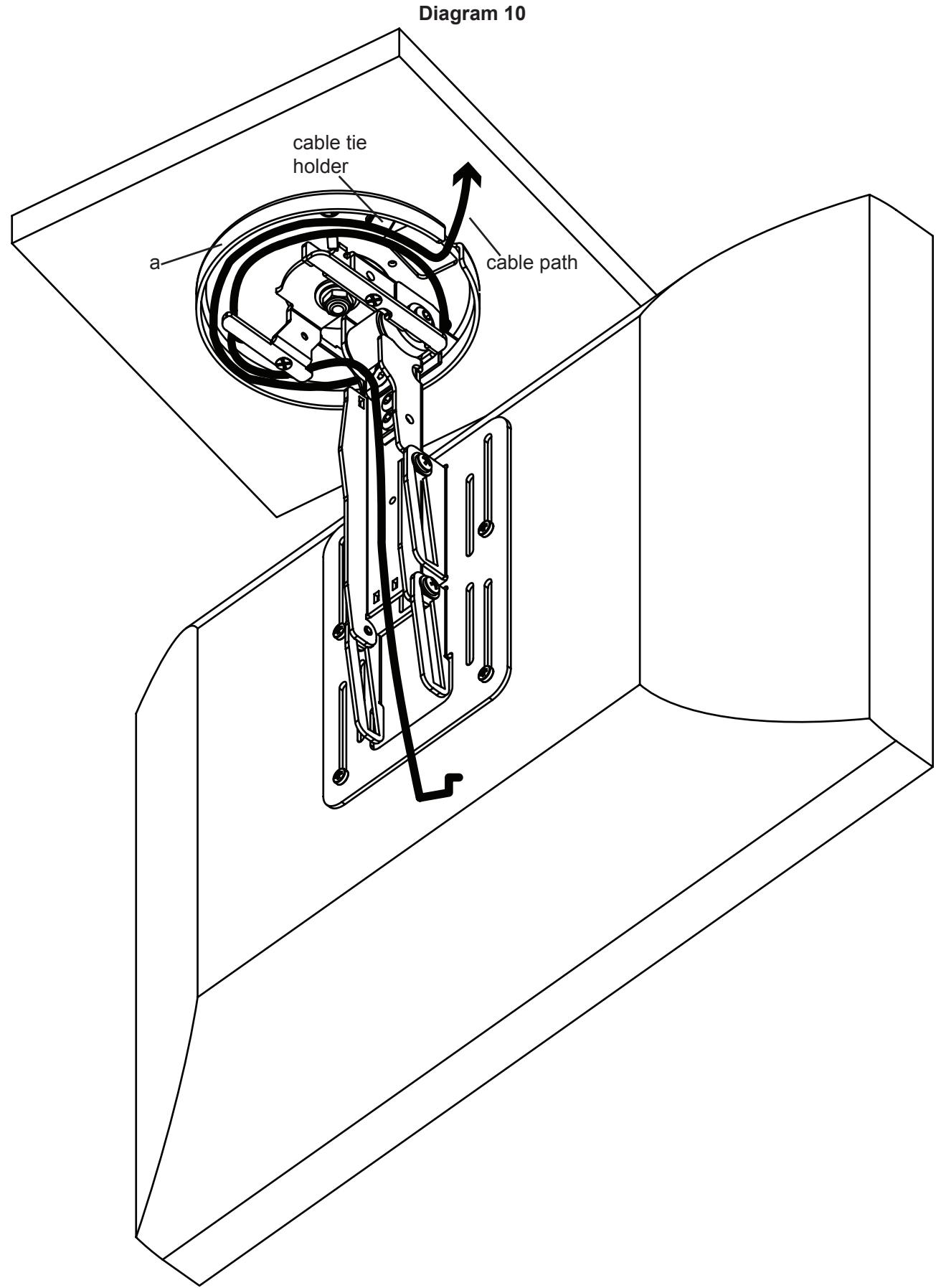
Step 10: Cable management (± 110^)
Swivel the Mount Assembly (a) 110^ either left or right. You will run the cables in the opposite direction. Cables must be wrapped a complete 360^ inside the base of the Mount Assembly. You can attach the Cable Ties (g) in locations marked in Diagram 8 below.