JAVA FURNITURE-JFA36 - Furniture SANUS - Free user manual and instructions
Find the device manual for free JAVA FURNITURE-JFA36 SANUS in PDF.

| Product Type | Storage cabinet for electronic equipment |
| Model | JFA36 |
| Brand | SANUS |
| Category | Furniture |
| Dimensions (approx.) | Approximately 100 cm x 40 cm x 50 cm (estimate) |
| Weight | Not specified |
| Material | Particle board, metal hardware |
| Number of shelves | 3 adjustable shelves |
| Door | 1 door with latch |
| Required tools | Phillips screwdriver, Allen key included, hammer (optional) |
| Main functions | Storage for audio/video equipment, TV stand (not included) |
| Care and cleaning | Wipe with a soft, dry cloth. Avoid abrasive cleaners. |
| Safety | Professional installation recommended. Check stability. |
| Spare parts | Available through SANUS customer service |
| Warranty | Not specified, contact manufacturer |
| General information | Assembly required. Instructions included. |
Frequently Asked Questions - JAVA FURNITURE-JFA36 SANUS
User questions about JAVA FURNITURE-JFA36 SANUS
0 question about this device. Answer the ones you know or ask your own.
Ask a new question about this device
Download the instructions for your Furniture in PDF format for free! Find your manual JAVA FURNITURE-JFA36 - SANUS and take your electronic device back in hand. On this page are published all the documents necessary for the use of your device. JAVA FURNITURE-JFA36 by SANUS.
USER MANUAL JAVA FURNITURE-JFA36 SANUS
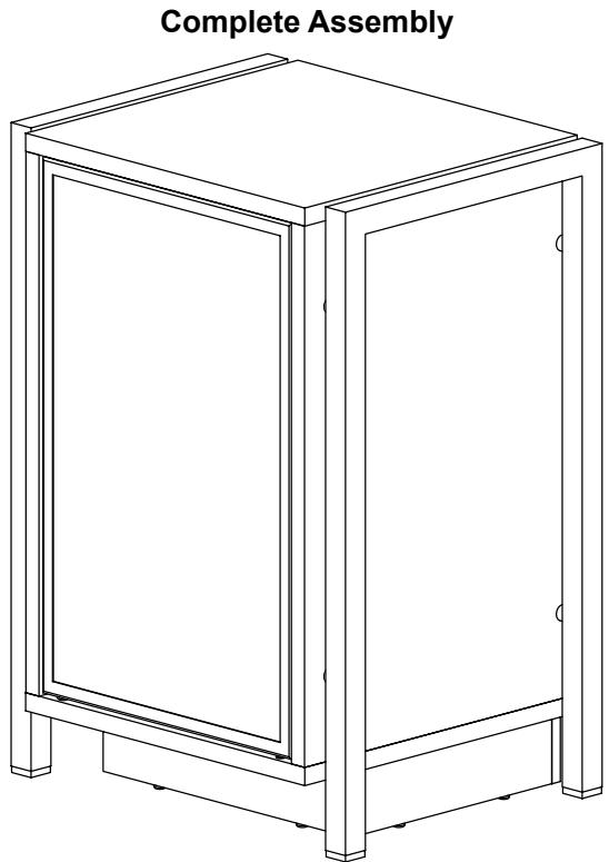
International Assembly Instructions for model JFA36
Thank you for choosing the Java Furniture line from Sanus Systems.
Safety Warning: If you do not understand these directions, or have any doubts about the safety of the installation, please call a qualified contractor or contact Sanus at 800.359.5520 or www.sanus.com. Check carefully to make sure that there are no missing or defective parts. Our customer service representatives can quickly assist you with installation questions and missing or damaged parts. Replacement parts for products purchased through authorized dealers will be shipped directly to you. Never use defective parts. Improper installation may cause damage or serious injury. Do not use this product for any purpose that is not explicitly specified by Sanus Systems. Sanus Systems can not be liable for damage or injury caused by incorrect mounting, incorrect assembly, or incorrect use. Please call Sanus Systems before returning products to the point of purchase.
Required Tools: Phillips screw driver, hammer or mallet (optional)
Supplied Parts and Hardware: Some parts not shown as actual size*
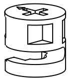
(14) Cam - a

(8) M6 Bolt - d
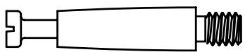
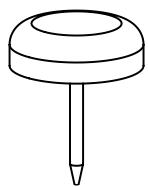
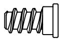
(14) Cam Pin - b

(8) Rubber Spacer - e
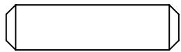
(18)Dowel-c

(8) Aluminum Spacer - f
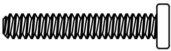
(4) Base Bolt - g
(8) Carpet Glide - h
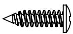

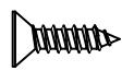
(16) Back Panel Screw - i
(1) Allen Key - j*
(12) Shelf Pin - k
(12) Shelf Pin Screw - 1
(1) Door Latch - m
(4) Latch Screw - n
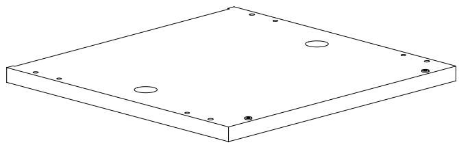
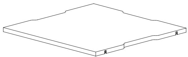
(1) Top - o
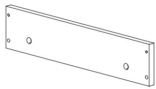
(2) Main Base Rail - q
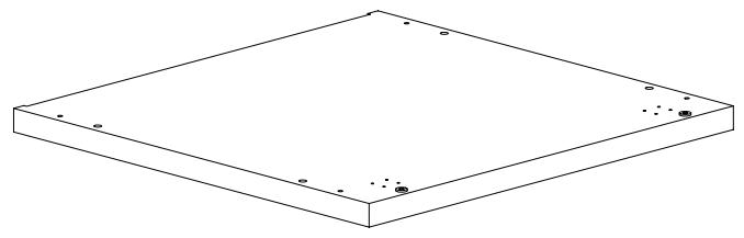
(1) Bottom - p
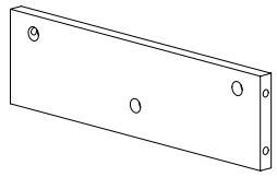
(2) Side Base Rail - r
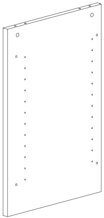
(1) Left Side Panel - s
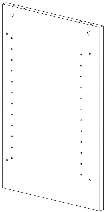
(1) Right Side Panel - t
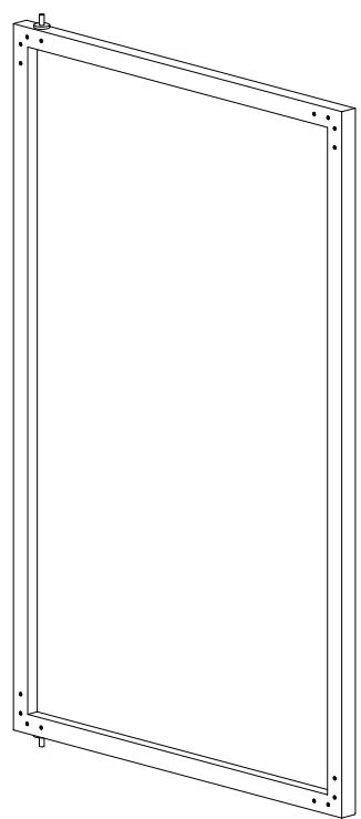
(1) Door - u
(2) Leg - v

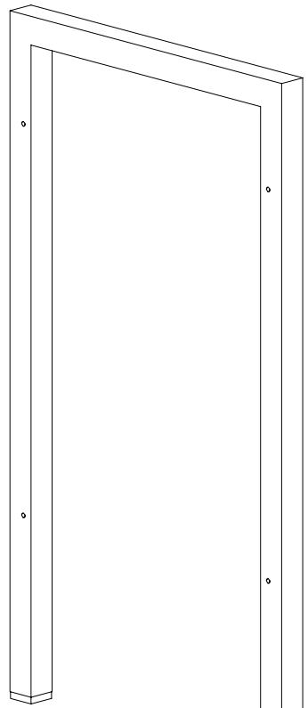
(2) Back Panel - w
(3) Shelf - x
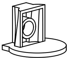
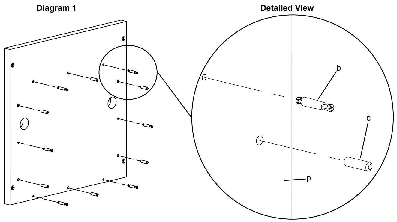
Thread a Cam Pin (b) into each threaded hole and insert a Dowel (c) into each adjacent hole in the Bottom (p). Tighten each with a Phillips screw driver. See Diagram 1 for assistance.
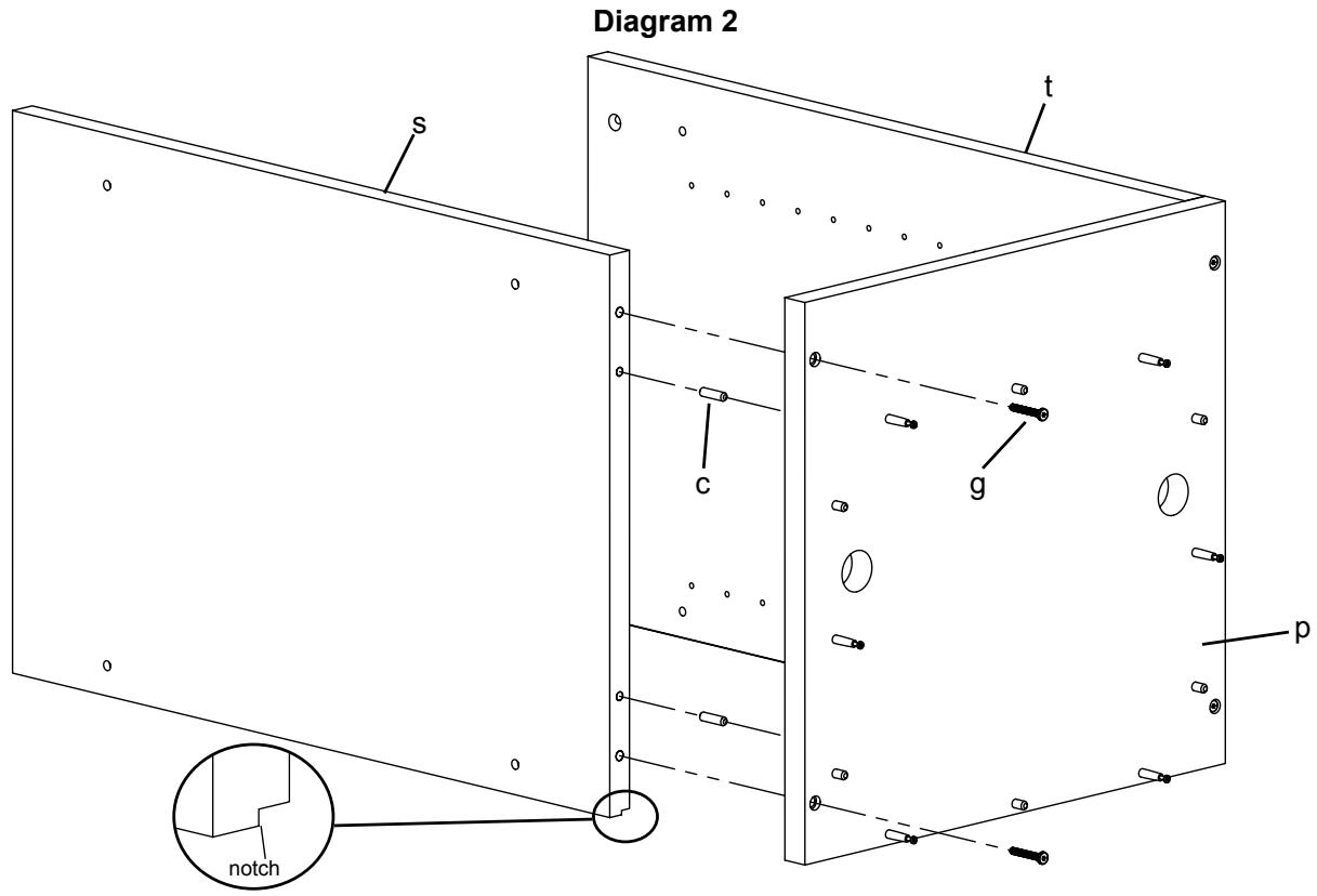
Step 2: Add Side Panels
Orient the Side Panels (s,t) so the notch is facing the ground and the shelf holes are facing each other. Insert a Dowel (c) into each hole (closest to the center in the bottom of each Side Panel). Insert a Base Bolt (g) through the Bottom (p) and into each Side Panel. Tighten each Base Bolt with the Allen Key (j). See Diagram 2 for Assistance.
Step 3: Base Assembly
Insert 10 Cams (a), four Cam Pins (b) and four Dowels (c) into the Main Base Rail (q) and Side Base Rail (r). Tighten each Cam Pin with a Phillips screw driver. Make sure the arrow on each Cam is pointed toward the closest hole. Press fit each rail together until a solid rectangle is formed. Tighten each Cam that corresponds with a Cam Pin in a clockwise motion to secure the Rails together. See Diagram 3 for assistance.
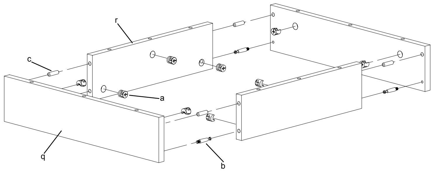
Diagram 3
Step 4: Add Base Assembly to Bottom
Align the assembled base frame so the holes line up with the Dowels (c) and Cam Pins (b) on the Bottom (p). Proceed to tighten all six of the Cams (a) on the Rails (q,r) that correspond with the Cam Pins on the Bottom so the assembled base frame is secure. See Diagram 4 for Assistance.
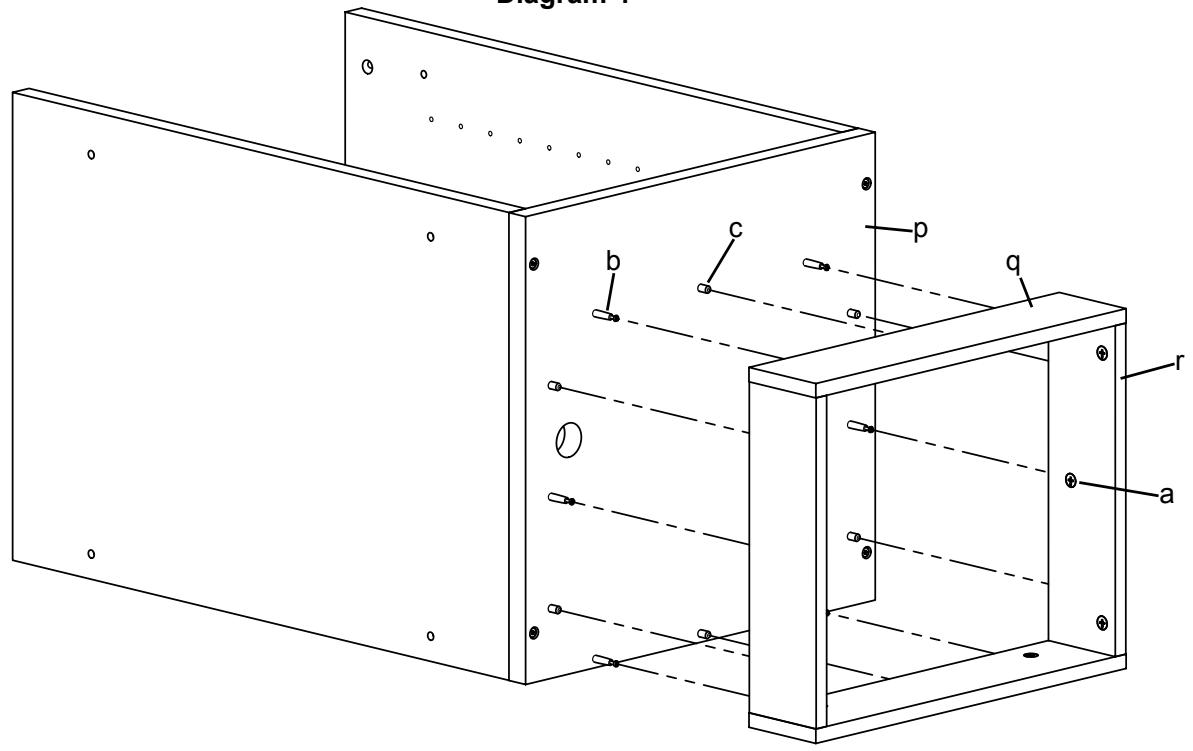
Diagram 4
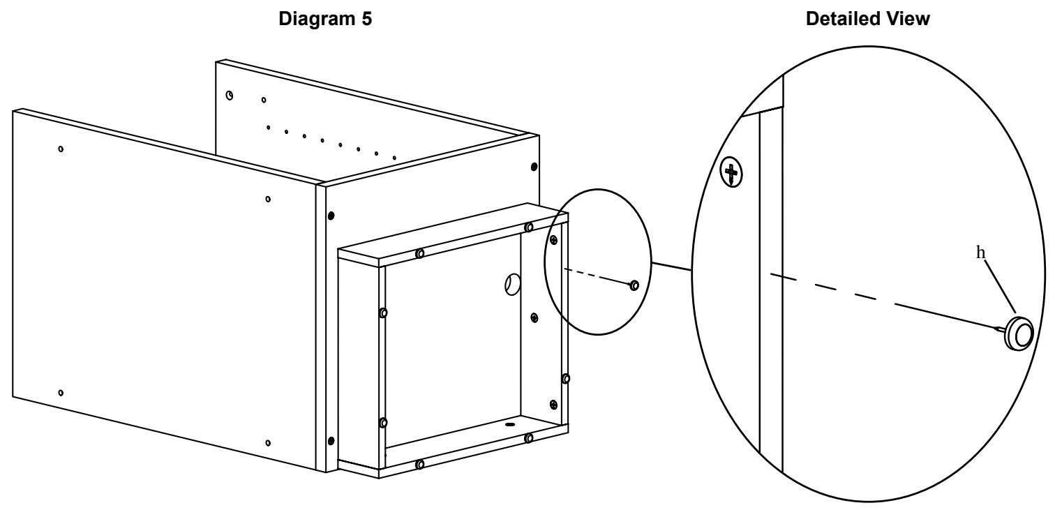
Gently tap the Carpet Glides (h) into each frame assembly. See Diagram 5 for Assistance.
Step 6: Add Door Latch
Attach the Door Latch (m) to the Top (o) with the four Latch Screws (n). Tighten each Latch Screw with a Phillips screw driver. See Diagram 6 for assistance.
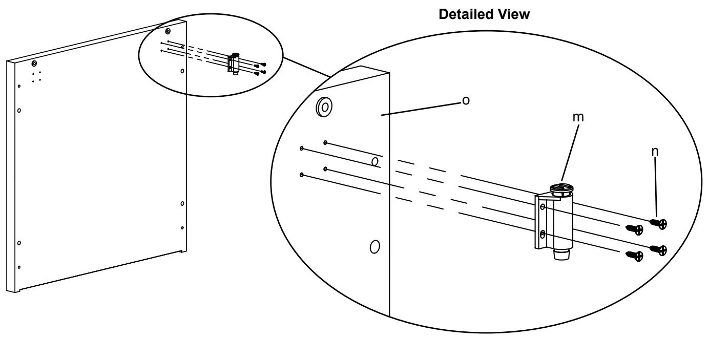
Diagram 6
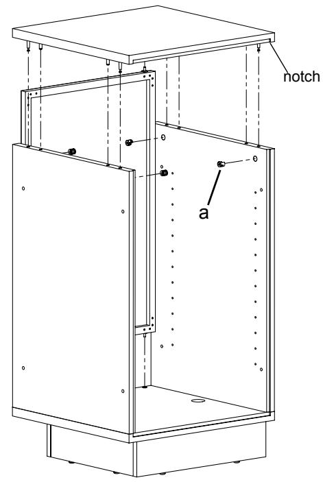
Insert a Cam Pin (b) into each threaded hole and insert a Dowel (c) into each adjacent hole in the Top (o). Tighten each Cam Pin with a Phillips screw driver. See Diagram 7 for assistance.
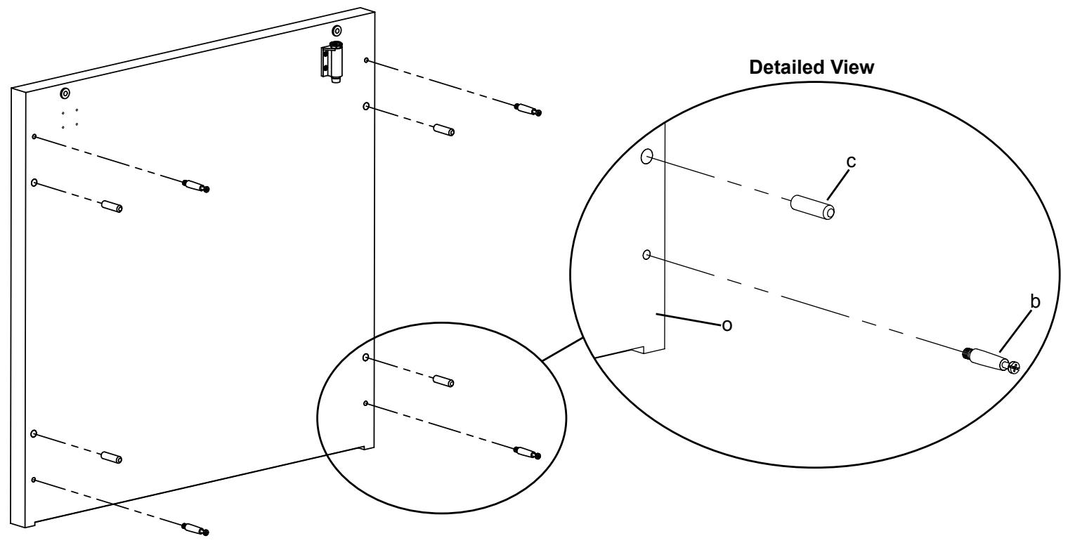
Diagram 7
Step 8: Add Door and Top
Gently position the cabinet assembly so it is up-right and resting on the base. Insert a Cam (a) into each Side Panel (s,t). Make sure the arrow on each Cam points toward the appropriate Cam Pin in the Top (o). Insert the Door (u) into the base so the pivot side is opposite from the Door Latch (m). Fit the Top onto the Side Panels so the Cam Pins correspond with the Cams and the Door is secured in the top. Tighten each Cam in a clockwise motion. See the Diagrams below for assistance.
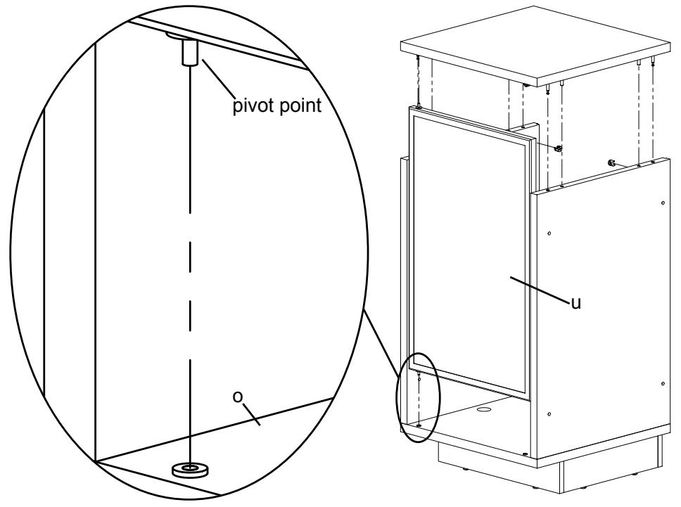
Detailed View
View from Front
View from Back
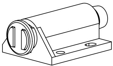
To add the Legs (v) first slide the Rubber Spacer (e) so it fits into the Aluminum Spacer (f). Take a M6 Bolt (d) and insert it through the Side Panel (s,t), the Spacer Assembly and finally thread it into the Leg. Repeat this process for the remaining holes on each leg. Tighten each M6 Bolt with the Allen Key (j). See Diagram 9 for assistance.
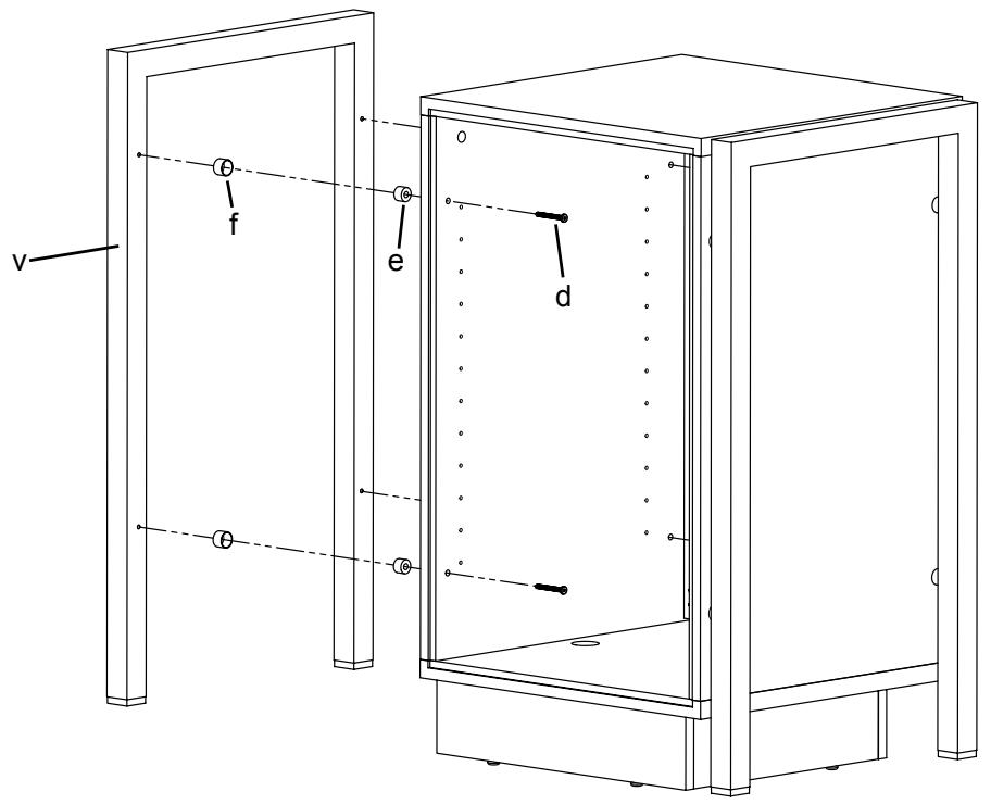
Diagram 9
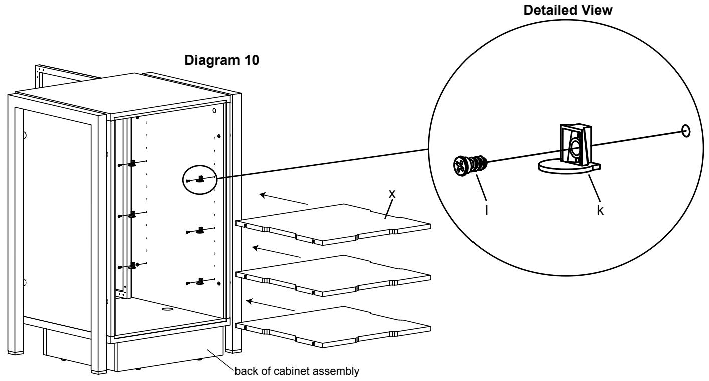
Step 10: Install Shelves
Insert a Shelf Pin Screw (l) through a Shelf Pin (k) and into the desired hole in the Side Panel (s,t). Tighten with a Phillips screw driver. Repeat process until all 12 Shelf Pins are installed. See the Detailed View of Diagram 10 for assistance.
Place each Shelf (x) in cabinet so they fit on top of the Shelf Pins. Press down firmly until it locks into place. See Diagram 10 for assistance.
Insert a Back Panel Screw (i) through the Back Panel (w) and into the cabinet assembly in the locations shown in Diagram 11. Tighten each Back Panel Screw with a Phillips screw driver. Repeat process for the other Back Panel.
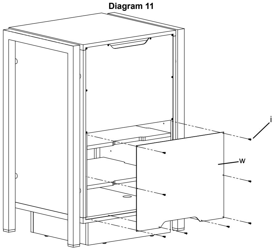
Note: Sanus recommends placing components and completing all necessary wire and cable hook-ups before attaching the Back Panels.