
VS 360 - Wireless video transceiver HAMA - Free user manual and instructions
Find the device manual for free VS 360 HAMA in PDF.
User questions about VS 360 HAMA
0 question about this device. Answer the ones you know or ask your own.
Ask a new question about this device
Download the instructions for your Wireless video transceiver in PDF format for free! Find your manual VS 360 - HAMA and take your electronic device back in hand. On this page are published all the documents necessary for the use of your device. VS 360 by HAMA.
USER MANUAL VS 360 HAMA
Wireless video transmitter
Precautions
Safety
- This equipment contains heat sensitive components. Maximum ambient temperature must not exceed 35^ Celsius.
- Humidity in rooms where this equipment is situated must not exceed a hygrometric level of 85% . If you have to use your equipment outside, avoid exposing it to rain water or to splashes. The transition from a cold environment to a hot one may cause condensation. Allow it to dry by itself before re-starting the equipment.
- In the event of prolonged absence, switch off the equipment by means of the on/off switch. Even when switched off, certain components remain live. In order to insulate it completely you must remove the plug from the main electricity supply.
- In the event of an electrical storm, it is advisable to disconnect the equipment from the electricity supply so as to avoid potentially damaging electrical or electromagnetic surges. To this end, make sure that the mains plug is easily accessible for disconnection.
- Disconnect the equipment immediately if you detect a smell of burning or smoke. Under no circumstances must you open the equipment yourself; you run the risk of electrocution.
Maintenance
- Clean the equipment with a soft cloth and a neutral detergent. The use of solvents, abrasive products or alcohol-based products is likely to damage the equipment.
Regulations
- This equipment must only be installed inside. Its use is restricted to private radio transmission. Connection to a public or independent network, or to an outside aerial is prohibited.
Under no circumstances should this appliance be put to industrial use. It is designed solely for domestic operation.
THOMSON disclaims all responsibility in the event of use that does not comply with the present instructions.
Principles of operation
What is this equipment for?
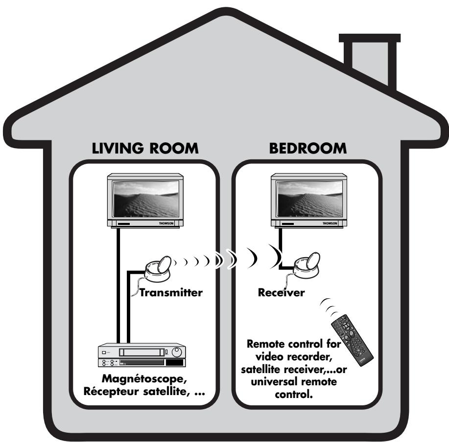
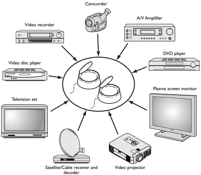
The Video Sender VS 360/460 permits the relay of an Audio-Video signal from your main set-up to a second television set located in another room and equipped with a scart connection (or RCA/Cinch). The main set-up is the place in which you have chosen to install the majority of your equipment (television set, video recorder, satellite receiver, DVD player...) you can operate the units from the room with the second television set by using their remote controls, or with a universal remote control.
You can play and hear music if you connect the transmitter to a suitable outlet (AUDIO OUT), and the receiver to an amplifier (AUDIO IN) placed in another room. For the link-up you will need to obtain 1 cinch/cinch cable (not supplied with equipment).
If you already have a Thomson plasma screen monitor or video projector, the Video Sender will ease your placing of these items where you most want them to be, thanks to eliminating all problems related to long cable runs.
Installation of transmitter
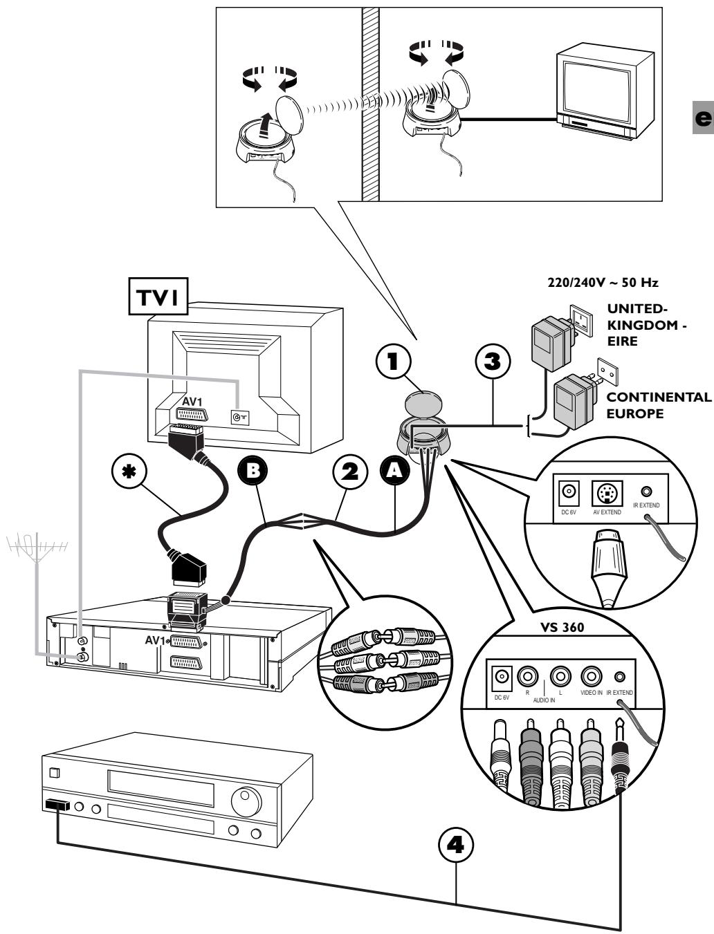
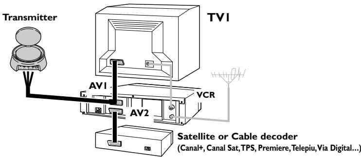
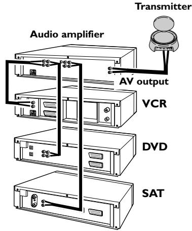
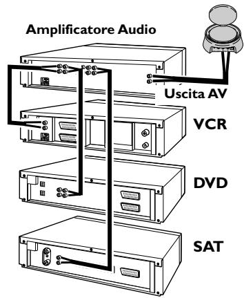
I. Place the transmitter (I) near the source equipment (VCR player, DVD player, etc.) from which you want to transmit video or audio output, and connect it with the two cords (2 A and 2 B) making sure you respect the color coding of the 3 cinch plugs (red and white for audio, yellow for video). Connect the TV set to a suitable outlet from the VCR player or DVD player (AVI).
Obtain a (non-supplied) SCART-TV set connector and connect the TV set to the 2B adapter already connected to the VCR player or DVD player as shown on Page 5 (see item marked * on Page 5).
- Fit the mains supply lead (3) to the transmitter and plug it into a 220/240V 50Hz mains power supply.
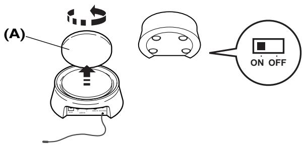
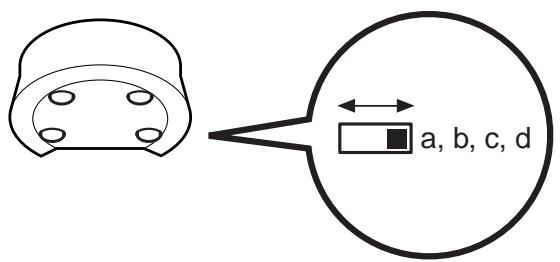
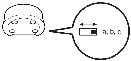
- Carefully extend the antenna of the transmitter (I) and orient it towards the room where your second TV set (TV2) is located. Circular antennas must be oriented so that the surfaces with inscriptions are face to face. Turn on (position ON) the transmitter and receiver, using the ON/OFF switch located on its lower side. Place the channel selectors of the transmitter and the receiver on the same channel (same letter).
-
Fit the lead (4) following these stages:
-
connect the jack plug to the IR EXTEND socket,
- unwind the lead and place one cell near the infrared window of the unit to be operated (video recorder or other),
- after installing the receiver (see Pages 6 and 7), ask someone to use the remote control of that equipment item to be controlled from the room where the second (TV2) is located,
-
by moving the cell around in front of the unit to be operated you will find the location that permits its control from the other room. You must fix the cell in that position. Usually, this will be a more or less large, transparent area located on the front of the unit.
-
Remove the protective self-adhesive film from the infrared cell of cord (4) and affix it to the infrared-sensitive panel of the equipment to be remote controlled. The cordon has 3 cells in order to let you play video and audio from 3 equipment items connected to the (TVI) set (see Diagram 2 on Page 10).
Installation of receiver
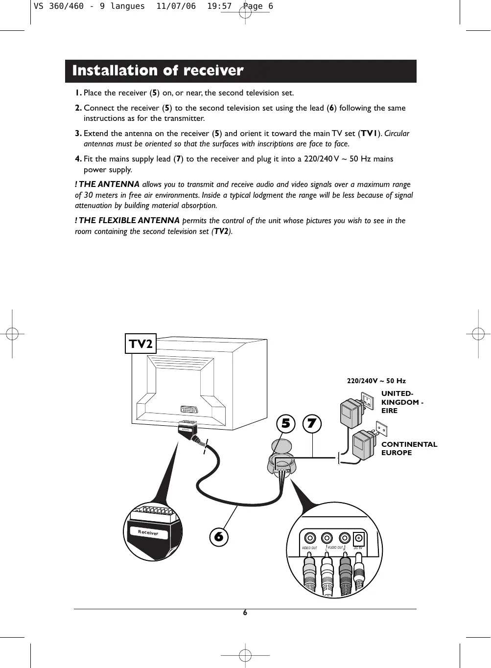
I. Place the receiver (5) on, or near, the second television set.
2. Connect the receiver (5) to the second television set using the lead (6) following the same instructions as for the transmitter.
3. Extend the antenna on the receiver (5) and orient it toward the main TV set (TVI). Circular antennas must be oriented so that the surfaces with inscriptions are face to face.
4. Fit the mains supply lead (7) to the receiver and plug it into a 220/240V 50Hz mains power supply.
! THE ANTENNA allows you to transmit and receive audio and video signals over a maximum range of 30 meters in free air environments. Inside a typical lodgment the range will be less because of signal attenuation by building material absorption.
! THE FLEXIBLE ANTENNA permits the control of the unit whose pictures you wish to see in the room containing the second television set (TV2).

Instructions for use
I. Switch on the transmitter (1) and the receiver (5) by switching their ON/OFF buttons to the ON position.
2. Make sure that the transmitter and the receiver are set to the same channel by checking the position of the selectors located under the casing. They must be set to the same channel (same letter).
3. Switch on your equipment (television sets, video recorders ...) in both rooms.
4. Using the remote control of the unit whose pictures you wish to see, and from the room containing the second television set (TV2), select the channels or video functions (or others) according to the unit you are controlling.
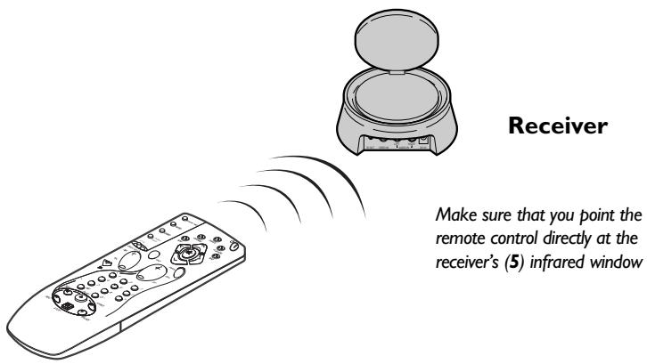
Make sure that you point the remote control directly at the receiver's (5) infrared window
Special operating details:
- No picture on TV2? If you fail to obtain the desired picture on the second television set TV2, select the AV socket, to which the receiver (5) is connected, using the television's remote control.
- Using a decoder (in France: Canal +, TPS, etc.) on your TV2? To have clear images on your second TV set (TV2), output from the decoder must pass through a VCR player, placed in (AV2) mode or set to the channel number assigned for the encrypted TV channel.
Use of a monitor? If your second television set does not have a connection for an outside aerial (terrestrial reception), or if it is a monitor, you will be able to see the channels in the room containing the second television set by selecting those of the video recorder with its remote control. - The picture is scrambled? The running of certain equipment (micro-wave ovens, digital telephone DECT, un-shielded acoustic loudspeakers, etc...) may interfere with signal transmission. Ensure that they are kept away from the transmitter and the receiver or switch them off.
Improvement of picture and sound
You will obtain optimal service operation of your Video Sender by correctly orienting the antennae (A). However, reflected signals or other signal degrading factors can affect good quality signal transmission. In this case, readjust antennae positions or slightly move the transmitter or receiver until you get crystal clear reception.
Transmitter / Receiver
If no picture is obtained,
check that the transmitter and the receiver have not been installed in the reverse order (each unit corresponds either to the input or to the output of the Audio-Video signal). Check that they have been properly connected and that they are switched on (ON position). Ensure that the channel selector is set to the same letter on both units.
If transmission is blurred or scrambled,
choose another channel but make sure that it is identical on both units.

Transmitter / Receiver
Relay of pictures from several units
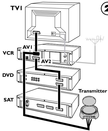
If you have several equipment items (VCR player, satellite receiver, DVD player, etc.) in your main equipment room and want to transmit and receive audio and video signals to a second TV set, connect your equipment items as shown in the Diagrams on following pages. Usually, the units are connected in series, the last unit having a free scart connection that you can use for the connection of the transmitter.
! These diagrams represent some connection possibilities the operation of which depends on the type of unit, its sockets and the signals it produces. There exist other connections that you might perhaps wish to try if diagrams 1 to 3 here are not satisfactory. If this is the case, ask your dealer for assistance.
! As a general rule, remember to switch off units not in use. Also, refer to the manufacturers' instructions to see if there are any particularities regarding connection or use. Certain units may need to have their input scart connection "programmed".
! In all cases the transmitter must be connected to a scart connection that produces an Audio-Video signal Out. Refer to the manufacturer's instructions for confirmation of this.
General information on connections...
1
3 AUDIO
Technical characteristics
Power supply: 6V DC
VS 360/460 :4 channels (A:2.414 GHz - B:2.432 GHz - C:2.450 GHz - D:2.468 GHz)

Transmitter / Receiver (Sender) / (Empfänger)
Transmitter / Receiver (Sender) / (Empfänger)
Apropos Anschlüsse...
3 AUDIO
Transmitter (Emettitone)

Transmitter / Receiver (Emisor) / (Receptor)
Si no obtieneyinguna imagen,
Transmitter / Receiver (Emisor) / (Receptor)
Characteristicas techniques
Alimentación: 6V DC
VS 360/460
Transmitter / Receiver
(Zender) / (Ontvanger)

Transmitter / Receiver
(Zender) / (Ontvanger)


Transmitter / Receiver (Vysilač) / (Prijjimač)
Pokud obrzcela chybi,

Transmitter / Receiver (Vysilač) / (Prijjimač)
Receiver (Vevöegység)
Model and serial number
D-86651 Monheim/Germany
www.hama.com
Manufactured and commercialised by HAMA under THOMSON Trademark license
Dealer's address