
DYNABASS 400 - Bass Amplifier TRAYNOR - Free user manual and instructions
Find the device manual for free DYNABASS 400 TRAYNOR in PDF.

User questions about DYNABASS 400 TRAYNOR
0 question about this device. Answer the ones you know or ask your own.
Ask a new question about this device
Download the instructions for your Bass Amplifier in PDF format for free! Find your manual DYNABASS 400 - TRAYNOR and take your electronic device back in hand. On this page are published all the documents necessary for the use of your device. DYNABASS 400 by TRAYNOR.
USER MANUAL DYNABASS 400 TRAYNOR
natural_image
Line drawing of a three-tier electronic equipment unit with labeled 'TRAVFOR' on the front panel (no other text or symbols)MODEL TYPE: YS1027
DynaBass 400
BASS GUITAR AMPLIFIER
IMPORTANT SAFETY INSTRUCTIONS

This lightning flash with arrowhead symbol, within an equilateral triangle, is intended to alert the user to the presence of uninsulated “dangerous voltage” within the product’s enclosure
that may be of sufficient magnitude to constitute a risk of electric shock to persons.
The exclamation point within an equilateral triangle is intended to alert the user to the presence of important operating and maintenance (servicing) instructions in the
literature accompanying the appliance.
Instructions pertaining to a risk of fire, electric shock, or injury to a person
CAUTION: TO REDUCE THE RISK OF ELECTRIC SHOCK, DO NOT REMOVE COVER (OR BACK).
NO USER SERVICEABLE PARTS INSIDE.
REFER SERVICING TO QUALIFIED SERVICE PERSONNEL.
Read Instructions: The Owner's Manual should be read and understood before operation of your unit. Please, save these instructions for future reference and heed all warnings.
Clean only with dry cloth.
Packaging: Keep the box and packaging materials, in case the unit needs to be returned for service.
Warning: To reduce the risk or fire or electric shock, do not expose this apparatus to rain or moisture. Do not use this apparatus near water!
Warning: When using electric products, basic precautions should always be followed, including the following:
Power Sources
Your unit should be connected to a power source only of the voltage specified in the owners manual or as marked on the unit. This unit has a polarized plug. Do not use with an extension cord or receptacle unless the plug can be fully inserted. Precautions should be taken so that the grounding scheme on the unit is not defeated.
Hazards
Do not place this product on an unstable cart, stand, tripod, bracket or table. The product may fall, causing serious personal injury and serious damage to the product. Use only with cart, stand, tripod, bracket, or table recommended by the manufacturer or sold with the product. Follow the manufacturer's instructions when installing the product and use mounting accessories recommended by the manufacturer.
The apparatus should not be exposed to dripping or splashing water; no objects filled with liquids should be placed on the apparatus.
Terminals marked with the “lightning bolt” are hazardous live; the external wiring connected to these terminals require installation by an instructed person or the use of ready made leads or cords.
Ensure that proper ventilation is provided around the appliance. Do not install near any heat sources such as radiators, heat registers, stoves, or other apparatus (including amplifiers) that produce heat.
No naked flame sources, such as lighted candles, should be placed on the apparatus.
Power Cord
Do not defeat the safety purpose of the polarized or grounding-type plug. A polarized plug has two blades with one wider than the other. A grounding type plug has two blades and a third grounding prong. The wide blade or the third prong are provided for your safety. If the provided plug does not fit into your outlet, consult an electrician for replacement of the obsolete outlet. The AC supply cord should be routed so that it is unlikely that it will be damaged. If the AC supply cord is damaged DO NOT OPERATE THE UNIT.
Unplug this apparatus during lightning storms or when unused for long periods of time.
Service
The unit should be serviced only by qualified service personnel.
SUIVEZ TOUTES LES INSTRUCTIONS
Thank you for choosing the DynaBass 400. You'll discover this advanced bass amplifier has the potential to deliver a wide sonic spectrum perfect for your particular performance needs. Best of all, it has the ability to sound "right" with a minimum amount of knob twirling.
When you need the extras, they're all here:
- Selectable Solid-State or Tube input gain
- Inputs for either Passive (0 dB) or Active basses (-6 dB).
- A tube preamp, for warmth, and a solid-state output stage for definition.
- Gain and Distortion controls let you dial-in the perfect amount of warmth and even overdrive.
- The Distortion circuit can be activated by using the switch on the front panel or by using an optional footswitch.
• The Distortion Mix control lets you blend-in the amount of tube drive. - The Scoop control lets you tailor your sound precisely and uniquely by emphasizing lows and highs while reducing the midrange.
- Five-band, active tone shaping controls (including a fine-tunable Parametric Mid control).
- Footswitchable external effects patching with an Effects Return level control and footswitch jack.
- An easy-to-use Compressor provides detailed control of your bass dynamics.
- A separate selectable Limiter helps prevent output-stage clipping-distortion.
- A Tuner Out jack lets you keep your tuner connected without affecting your signal path so it's always available for quick reference and adjustments. The Mute button ensures that the audience doesn't hear you tuning.
• Balanced 14 -inch TRS and XLR line outs selectable between Pre-EQ (real D.I.) or Post-EQ. - Speakon™ and ¼-inch speaker outputs (all jacks are in parallel, min 4-ohm load).
• DynaBass 400 / DynaBass 400T combos feature a global Tweeter Defeat/Active Switch
Please take a little time to read the following instructions; then plug in, switch on, and unleash your musical creativity!
Traynor
text_image
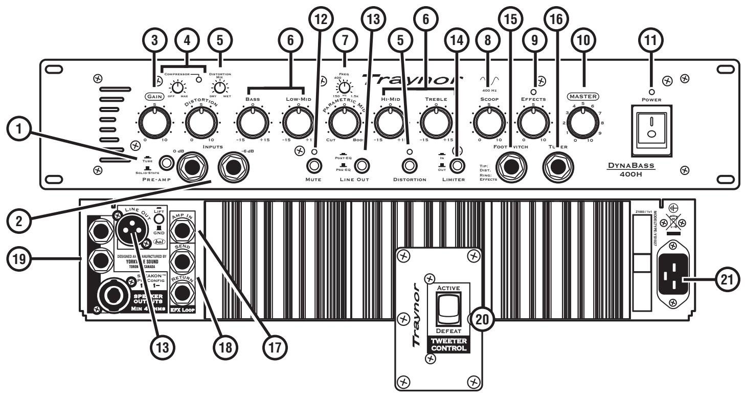
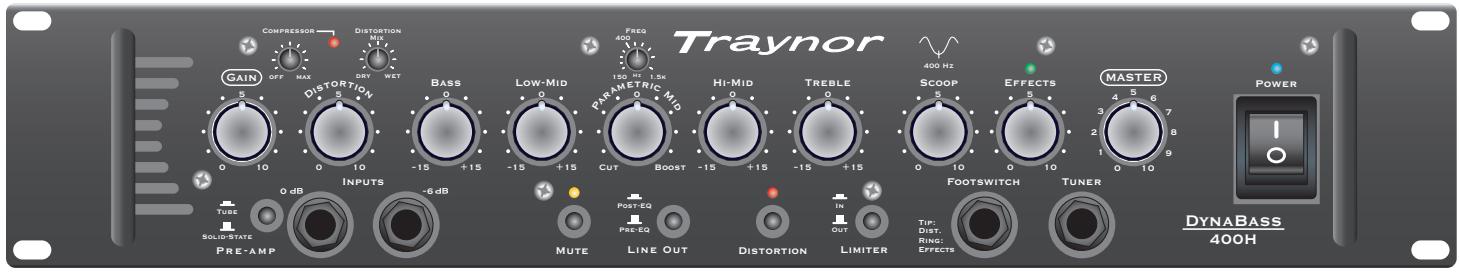
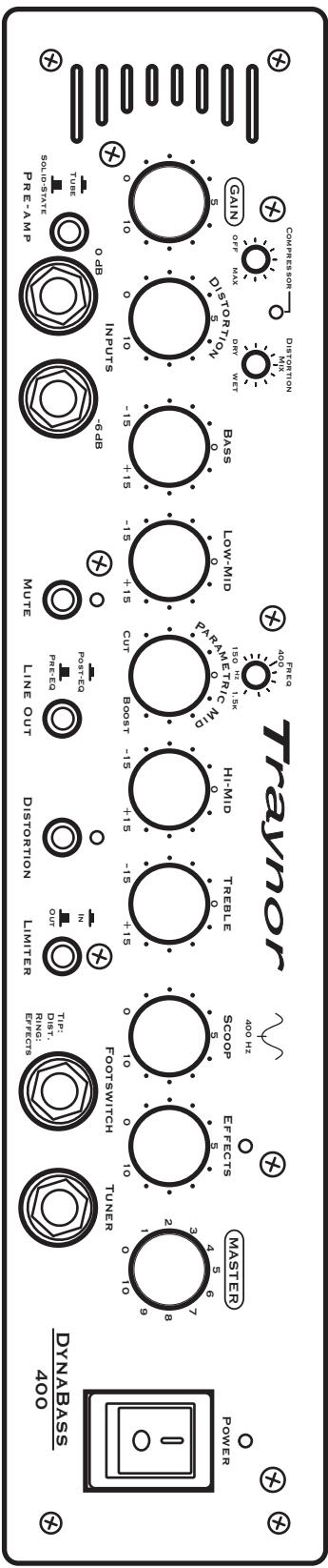
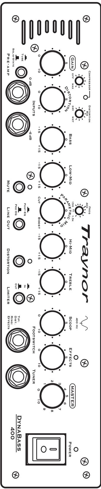
1 2 3 4 5 6 7 8 9 10 11 12 13 14 15 16 17 18 19 LINE OUT LIFT AMP IN GND Send SELECTED AND MANUFACTURED BY YORKI SOUND LIMEA SPXER OUTS MIN 4 SPX LOOP DISTORTION MIN DRIY WET BASS LOW-MID PREQ 400 MHz PARAMETER MIN CUT BOO HI-MID TREBLE OUT DISTORTION DISTORTION LINE OUT LINER TOP VITCH Foot Drop Effects TIMES MASTER POWER DYNABASS 400H ACTIVE DEFEAT TWEETER CONTROL Z1003 / 1x1 MODELATE: 75/15/227① Tube and Solid-State Pre-Amp mode switch
② 0dB / Passive and -6dB / Active Input Jacks – 14 -inch phone jacks.
③ Gain control
④ Adjustable Compressor
⑤ Distortion Mix and Distortion control
⑥ Tone Controls – Bass, Low-Mid, Hi-Mid and Treble.
⑦ Parametric Mid tone control
⑧ Scoop control.
⑨ Effects Return control and LED
⑩ Master control
⑪ Power LED and Power switch
⑫ Mute switch
⑬ Line Out XLR Jack and Selector Switch – Switch between Pre-EQ and Post-EQ settings
⑭ Selectable Limiter
⑮ Distortion and Effects Return Footswitch – ¼-inch TRS phone jack
⑯ Tuner out – 14 -inch phone jack
⑰ Amp In Jack – ¼-inch phone jack
⑱ EFX Send and EFX Return Jacks – ¼-inch TRS phone jacks
⑲9 Speaker Output jacks – ¼-inch and Speakon™ connectors
⑳ Tweeter Defeat / Active Switch (DB400 & DB400T combos only)
②1 AC Power connector
1. Preamp Select Switch
Depending on your preference, choose either solid-state or tube gain input for the preamp.
2. 0dB / Passive and -6dB / Active Inputs
We suggest the following: use the 0dB/Passive input for bass guitars with passive electronics, like single-coil and humbucking pickups; use the -6dB/Active input for active pickups (or extremely 'hot' pickups). However, you may prefer to run your active pickup bass guitar into the 0dB/Passive input for an intentional aggressive sound – you are in control.

User Tip: Don't use both inputs at the same time as they're not intended for connecting more than one instrument at a time.
3. Gain Control
The Gain control is a volume adjustment for the preamp, which is selectable between either solid-state or tube circuitry. The tube circuitry features a single 12AX7A (dual-triode) preamp tube. The Gain control is typically set around the middle for most basses. If your bass has an unusually low output, increase the Gain control to the desired level; conversely for higher output basses use a lower setting. Increasing the Gain control also affects the level of drive when the Distortion feature is engaged.
4. Compressor
To increase the consistency of your tone and further the performance of the power amplifier, we have provided an adjustable compressor. This compressor is simple to use, with only a simple threshold control to make adjustments. The compression ratio is 2:1 and the attack/release-time is preset optimally.

Note: To use the Compressor, rotate the control clockwise until the desired threshold is reached. It will be apparent to you audibly as well as visually; a red LED (located to the right of the control) will illuminate as the compressor limits the signal. The LED will also indicate how much compression is being applied by its intensity and duration.
5. Distortion Switch, Mix and Control
The Distortion feature controls the amount of tube-overdrive (saturation) in the signal. The tube-overdrive is powered by a 12AX7A, dual-triode preamp tube. Activate the circuit by depressing the Distortion mode switch or using the optional footswitch. The red LED above the Distortion switch, will illuminate indicating Distortion mode is active. To achieve higher levels of overdrive, increase the Gain control at the preamp stage. If you want your overdrive level to saturate into modern lead-style distortion, increase the Distortion control fully clockwise. Naturally, there will be some extra noise coming out of the amplifier at this high setting. This is a normal compromise when achieving so much overdrive.
User Tip: Many unique sounds can be obtained by changing some controls in conjunction with the Distortion control. Some bassists prefer minimal distortion with a lot of Scoop, some may prefer massive overdrive (and lots of midrange growl) and others may go for deep dry bass. These sounds can be achieved easily by adjusting the Scoop, the Distortion and the Distortion's Mix controls in conjunction with each other.

User Tip: The Distortion circuit can also be activated by an optional footswitch (AFS-2). A red LED, located directly above the Distortion switch, will illuminate. Some players find this useful as a boost for loud passages or soloing.
Note, when using the footswitch the front panel Distortion selection switch is deactivated.
The Distortion Mix control becomes active when the Distortion mode is activated. This control blends an underlying clean tone below the overdriven tone. In the Dry, counterclockwise setting, clean signal is allowed to dominate the mix, with no overdrive. When rotated clockwise, into the Wet region, the overdriven sound becomes more apparent. The Distortion overdrive will continue to increase until it is the dominant sound in the mix (fully Wet position). This helps you achieve a perfect Wet/Dry blend between a completely clean and completely saturated overdrive tone. This is a handy feature that puts you in control of your overdrive tone.
6. Tone Controls
Each tone control permits a wide range of adjustment. The five overlapping controls cover the entire audio spectrum. Each tone control permits a wide range of sonic adjustment. The Bass adjusts the level of the low frequency range, Low Mid the next range up, Hi Mid covers higher notes and middle harmonics and the Treble control regulates the upper harmonic range. Each tone control has a variable boost and/or cut of 15 db. The center position denotes a neutral or nominal setting. The Parametric Mid control is described in detail in section 7, below.
User Tip: It's a good idea, when starting out, to center all tone controls. While playing, adjust them until you achieve the desired sound. Remember, if the Parametric Mid control is set at 0, rotating the Frequency control will have no effect.
7. Parametric Mid Control
The Parametric Mid control enables adjustments to be centered on frequencies ranging from 150 Hz – 1.5 kHz.

User Tip: To use this control, set the position of the Parametric Mid level control to cut or boost. Rotate the Frequency control until the desired frequency range is found. Once the frequency range is chosen, adjust the Parametric Mid level until the desired cut or boost level is achieved.
User Tip: Try using the Parametric Mid in conjunction with the Scoop feature. When using the Parametric Mid, it's possible to enhance the Scoop's capabilities by letting the two tone-shaping controls work in tandem. If you like the added bottom of the Scoop but wish to soften the midrange at 1.0 KHz (but still maintain the higher frequencies); adjust the Parametric Mid Frequency control to 1.0 KHz and then use the Parametric Mid level control to cut as much as you need. The 400 Hz frequency has been conveniently marked on the Parametric Mid's Frequency control.
8. Scoop Control
The Scoop enhances the tone of the bass by shaping the mid frequencies around 400 Hz. By shaping the bottom-end fundamentals and high frequency brilliance subtleties normally hidden are revealed. The Scoop shapes specific upper and lower frequencies while notching particular mid frequencies. It utilizes a variable tone curve that reacts differently depending on where it is set. The result is a greatly expanded tonal range and control. As shown on the front panel, the center frequency of the scoop is centered around 400 Hz. If you desire more scoop, turn the parametric mid frequency control to 400 Hz and set the gain counterclockwise to cut until the desired amount is reached

Tip: As with the tone controls, it's recommended to set the Scoop control initially at the mid point. Adjust it slowly, either way, until the desired tone is achieved.
Tip: Combine the Scoop, the Distortion and Distortion Mix for unparalleled levels of tonal control. Set the Distortion and the Distortion Mix to their maximums and play your bass while slowly rotating the Scoop from its off position to its MAX position, you'll find the variation in the effect to be quite dramatic and yet very musical at the same time.
9. Effects Return Blend Control
Use the Effects Send jack to send a dry, un-effected signal to external effects unit. The externally processed signal then can return to the amplifier through the Effects Rtn jack. The Effects Rtn blend control regulates how much of the wet (effected signal) is blended with the dry signal (un-effected signal). This can range from totally dry (without effects) to mostly wet (effects applied).

Tip: If a wetter signal is desired, set the output signal from the external effects processor to a high output.
10. Master Volume Control
The Master volume control adjusts the overall signal level of the amplifier.
11. Power
The LED above the Power switch will illuminate when the unit is on.
12. Mute Switch
The Mute switch disengages the preamp signal from the Line Out and power amplifier, disabling signals sent to the mixing console and speaker cabinets. The Tuner Out jack is still enabled (see Tuner Out in the Rear Panel section).
13. Line Out Switch and XLR Line Out Jack
This jack is used to connect directly to mixing consoles. You may prefer to use this when performing live or recording in the studio.
Selecting the Pre-EQ option in the Line Out mode selection switch (located on the front panel) makes the Line Out behave like a typical D.I. box: it provides a pre-EQ and pre-EFX signal. The Post-EQ option sends the signal post-EQ and post-EFX, which enables the output to drive another amplifier or the mixing console. A Ground Lift (lifts Pin 1 of the XLR) switch is also provided to help when routing signals directly to other equipment or mixing consoles.
14. Selectable Limiter
In order to prevent hard clipping of the power amplifier, a selectable limiter is provided.
15. Distortion and EFX-Return Footswitch Jack
A dual footswitch jack can be used to switch the Distortion and the external Effects on and off.
The footswitch uses a standard TRS 14 -inch based dual footswitch (e.g. Yorkville AFS-2). When either effect is activated, corresponding LED's on the amplifier will illuminate on and off. The Effects are only switchable by the footswitch, but the Distortion can be enabled or disabled by either the footswitch or the switch located on the front panel. The footswitch control overrides the front panel switches.
16. Tuner
The Tuner out 14 -inch jack sends the signal from your bass guitar to an outboard instrument tuner. Simply connect one end of a 14 -inch shielded cable to the Tuner Out jack and the other to the instrument tuner. Pressing in the Mute button will mute the output to the speakers as well as to the line out, but not the Tuner out.
Tip: Leave your tuner connected to the Tuner Out jack and Mute the signal any time you wish to tune in silence. This is a very handy feature when onstage as the unpleasant sound of tuning is not something you wish the audience to hear amplified through your performance speakers or the sound system.
Note: When the Mute switch is engaged, a signal will not be sent to the mixing console through the XLR output.
17. Amp In 14 -inch Jack
The balanced Amp In jack is located on the rear panel of the DynaBass 400. The Amp In jack provides a direct path to the DynaBass 400's power amplifier, bypassing the preamp. The Master control still controls the overall output level. Multiple DynaBass 400's can be linked together by using the DynaBass 400's balanced XLR Line Out to additional DynaBass 400 Line In jacks.
18. Effects Send and Return 14 -inch Jacks
External effects processors are provided with a balanced post-EQ signal from the Effect Send jack. The balanced Return jack is used to return effects (processed audio signals) back into the DynaBass 400. The Effects Return control, located on the front panel, regulates the blend of effected and un-effected signal. This input can also be used as an auxiliary input for mixing in a secondary source of audio such as pre-recorded music.
User Note: The Effects Send jack can also be used as an additional line out for sending signals to another power amplifier. The output of this jack is not muted when the Mute switch is enabled.
19. Speaker Output Jacks
The 14 -inch and Speakon ^™ jacks are used to connect extension speaker cabinets. All speaker output jacks are in connected in parallel; the minimum load impedance is 4-ohms (e.g. two 8-ohm or four 16-ohm cabinets).
20. Tweeter Defeat / Active Switch (DynaBass 400 & DynaBass 400T combos only)
The Tweeter Defeat / Active toggle switch provides you with the option of playing classic bass tones (tweeter defeated) or more modern full-range tones with increased high frequency definition (tweeter active). You be the judge of what sound you prefer!
21. AC Power Receptacle
The DynaBass 400 is equipped with a standard grounded IEC power receptacle. Only use the supplied removable power cord or one that uses a minimum of 16 gauge wire.
22. Preamp Tube Replacement
Use only Yorkville Sound part number “12AX7SORTED” when replacing preamplifier tubes as they have been specifically selected for this product. Please refer to the Service Manual for more information.
text_image
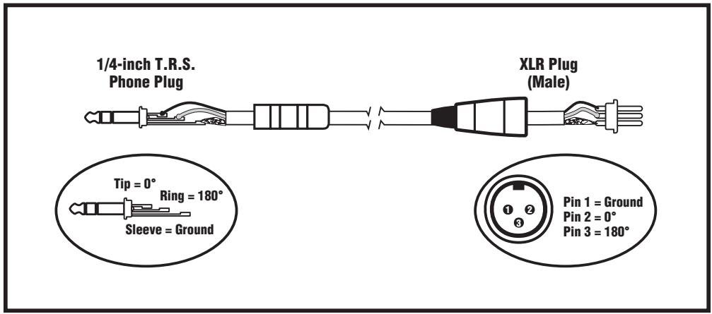
1/4-inch T.R.S. Phone Plug XLR Plug (Male) Tip = 0° Ring = 180° Sleeve = Ground Pin 1 = Ground Pin 2 = 0° Pin 3 = 180°Balanced 1/4-inch T.R.S. to Balanced XLR
text_image
Traynor GAIN OFF MAX Distortion DISTORTION M1 DRY WET BASS 0 LOW-Mid 0 Preq 400 Hz 150 Hz 1.5k PARAMETRIC MID 0 Hi-Mid 0 TREBLE 0 400 Hz SCOOP 5 EFFECTS 5 MASTER 3 POWER 2 1 0 10 9 TOPS FINE 10 FOOTSWITCH TUNER TIP: Dist: RING: EFFECTS DYNABASS 400H INPUTS -6 dB MUTE POST EQ PRE EQ LINE OUT DISTORTION LIMITER TUBE SOLID-STATE PRE-AMP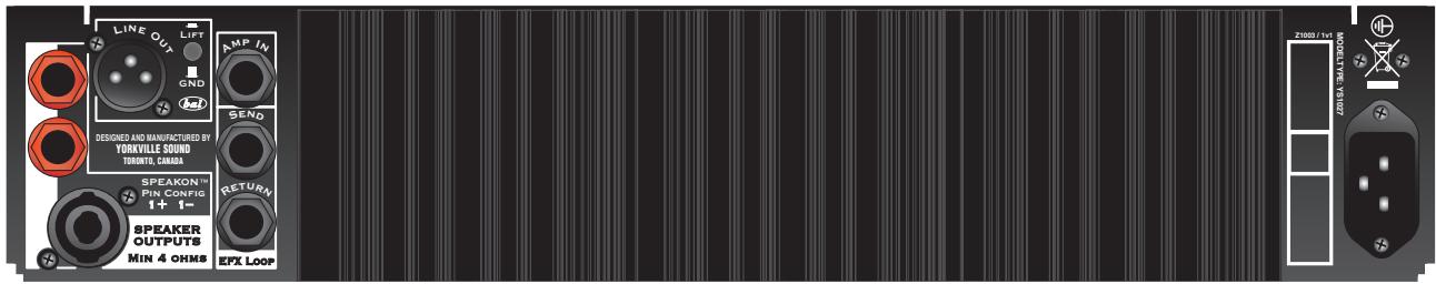
text_image
LINE OUT LIFT GND AMP IN SEND RETURN SPEAKON™ PIN CONFIG 1+ 1- SPEAKER OUTPUTS MIN 4 OHMS EFX LOOP DESIGNED AND MANUFACTURED BY YORKVILLE SOUND TORONTO, CANADA 2000 / FL MODE TYPE: V1007DynaBass 400/400T/400H
text_image
1/4-inch T.R.S. Phone Plug XLR Plug (Male) Tip = 0° Ring = 180° Sleeve = Ground Pin 1 = Ground Pin 2 = 0° Pin 3 = 180°Balanced 1/4-inch T.R.S. to Balanced XLR
Traynor
DYNABASS
400
Specifications
| Power @ min. impedance (Watts) | 250 @ 8 ohms / 400 @ 4 ohms |
| Minimum Impedance (ohms) | 4 |
| Burst Power - 2 cycle | 400 Watts @ 8 ohms / 725 Watts @ 4 ohms |
| Speaker Configuration - LF (Size / Power) | DynaBass 400 combo: 15-inch / 250 W |
| DynaBass 400T combo: 2 x 10-inch / 200 Watts each | |
| Speaker Configuration - HF (Size / Power) | DynaBass 400 combo: 3.5-inch Tweeter / 50 Watts |
| DynaBass 400T combo: 3.5-inch Tweeter / 50 Watts | |
| Frequency Response | 20 Hz - 20 kHz +/- 3dB |
| Input Channels | 1 |
| Channel 1 - inputs | 2 x 1/4-inch (0 dB and -6 dB) |
| Channel 1 - controls | Gain, Distortion (w/mix), Compressor |
| 5-Band EQ, Parametric Mid, Scoop, Effects Rtn & Master | |
| Channel 1 - switches | Mute, DI/Line Output, Distortion, Limiter and Solid State/Tube Preamp |
| Input Sensitivity | 0 db = 40mV |
| Line Out (type / configuration) | Balanced XLR, Pre / Post EQ with Ground Lift Switch |
| Line Out Sensitivity (Vrms) | <1 |
| Effects Loop / Location | Rear |
| Effects Return Sensitivity (Vrms) | <1 |
| LED Indicators | Power, Compressor, Mute, Distortion and Effects |
| Protection | Thermal, Short Circuit |
| Limiter / Switchable | Yes / Yes |
| External speaker output / location | 2x 1/4-inch & 1x SpeakonTM |
| Dimensions (DWH, inches) | DynaBass 400H: 12 x 19 x 3.5 |
| DynaBass 400H w/sleeve: 16 x 20.5 x 7 | |
| DynaBass 400: 15 x 24 x 23.5 | |
| DynaBass 400T: 15 x 24 x 22.5 | |
| Dimensions (DWH, cm) | DynaBass 400H: 30.5 x 48 x 9 |
| DynaBass 400H w/sleeve: 41 x 52 x 18 | |
| DynaBass 400: 38 x 61 x 60 | |
| DynaBass 400T: 41.30 x 54 x 18.40 | |
| Weight (lbs / kg) | DynaBass 400H: 23/10.5; DB400H w/Sleeve: 39.5/18 |
| DynaBass 400 82/37; DB400T: 85/39 |
Spécifications
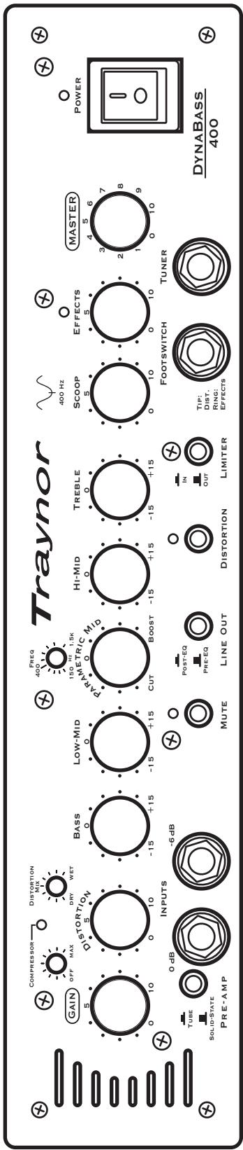
Dyndass 400 user settings
DynaBass 400 User Settings
Notes:
text_image
Traynor Power DynABass 400 Power MasterR Footswitch Turner FloorSwitch Tuner Tip: Dirt. Bisf. Erfects Limiter OUT IN Mute Line Out Distortion Prc-EA Post-EC OUT O 15 +15 -15 +15 -15 +15 -15 +15 -15 +15 -15 +15 -15 +15 -15 +15 -15 +15 -15 +15 -15 +15 -15 +15 -15 +15 -15 +15 -15 +15 -100 Hz 3.6 7 8 9 2 4 5 6 7 8 0 9 0 10 0 10 0 10 0 10 0 10 0 10 0 10 0 10 0 10 0 10 0 10 0 10 0 10 0 10 0 10 0 10 0 10 0 10 0 10 0 10 0 1Notes:
text_image
Traynor Power DYNABASS 400 Master Footswitch Turner Tip: DTI. Rings: Flects Limiter OUT IN Distortion PNC: FPE-3A Post-3A Mute Line Out OUT 6-15 +15 -15 +15 -15 +15 -15 +15 -15 +15 -15 +15 -15 +15 -15 +15 -15 +15 -15 +15 -15 +15 -15 +15 -15 +15 -15 +15 -15 +15 -15 +12 -15 +12 -15 +12 -15 +12 -15 +12 -15 +12 -15 +12 -15 +12 -15 +12 -15 +12 -15 +12 -15 +12 -15 +12 -15 +12 -15 +12 GAIN OFF MAX Distribution mix Distribution mix 400 Hz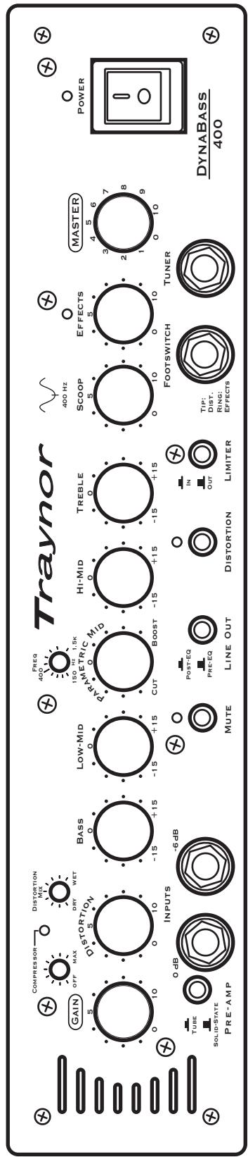
text_image
Traynor GAIN OFF MAX DISTORTION MIX DRY WET BASS 0 -15 +15 LOW-MID 0 -15 +15 PARAMETRIC MID 0 Cut Boost -15 +15 HI-MID 0 -15 +15 TREBLE 0 -15 +15 SCOOP 5 0 10 EFFECTS 5 0 10 MASTER 4 5 6 POWER 3 7 2 8 1 9 FootSWITCH TUNER TIP: DIST. RING: EFFECTS DYNABASS 400 INPUTS -6 dB TUBE 0 dB SOLID-STATE PRE-AMP MUTE Post-EQ PRE-EQ LINE OUT DISTORTION IN OUT LIMITER| Notes: |
text_image
Traynor GAIN OFF MAX Distortion Mix DRY WET FREQ 400 Hz 5 10 5 10 -15 +15 -15 +15 LOW-MID 150 Hz 1.5K 0 0 PARAMETRIC MID HI-MID TREBLE 0 0 CUT BOOST -15 +15 -15 +15 -15 +15 SCOOP EFFECTS MASTER 5 5 7 8 9 10 10 Footswitch Tuner TUBE SOLID-STATE PRE-AMP 0 dB INPUTS -6 dB MUTE POST-EQ PRE-EQ LINE OUT DISTORTION LIMITER TIP: DIST. Ring: EFFECTS DYNABASS 400| Notes: |
Dyndass 400 user settings
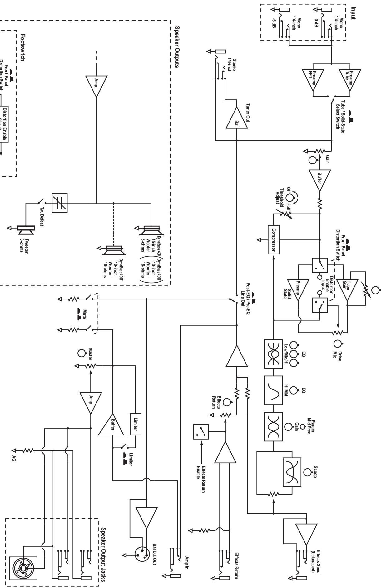
BLOCK-DIAG-DynaBass400-400T-400H-01-1v2
flowchart
graph TD
    subgraph Speaker_Outputs
        A["Speaker Output jacks"] --> B["Amp"]
        B --> C["Amplifier"]
        C --> D["Filter"]
        D --> E["Master"]
        E --> F["Mute"]
        F --> G["Limiter"]
        G --> H["Jammer"]
        H --> I["Bal DL Out"]
        J["Speaker Outputs"] --> K["Amp"]
        K --> L["Amplifier"]
        L --> M["Filter"]
        M --> N["Master"]
        N --> O["Limiter"]
        O --> P["Bal DL Out"]
        Q["Input"] --> R["Turn Out"]
        S["Speaker Outputs"] --> T["Speaker Outputs jacks"]
        U["Speaker Outputs"] --> V["Speaker Outputs"]
        W["Speaker Outputs"] --> X["Speaker Outputs"]
        Y["Speaker Outputs"] --> Z["Speaker Outputs"]
        AA["Speaker Outputs"] --> AB["Speaker Outputs"]
        AC["Speaker Outputs"] --> AD["Speaker Outputs"]
        AE["Speaker Outputs"] --> AF["Speaker Outputs"]
        AG["Speaker Outputs"] --> AH["Speaker Outputs"]
        AI["Speaker Outputs"] --> AJ["Speaker Outputs"]
        AK["Speaker Outputs"] --> AL["Speaker Outputs"]
        AM["Speaker Outputs"] --> AN["Speaker Outputs"]
        AO["Speaker Outputs"] --> AP["Speaker Outputs"]
        AQ["Speaker Outputs"] --> AR["Speaker Outputs"]
    end

    subgraph Output
        AS["Effect Return"] --> AT["Effects Return"]
        AU["Effect Return Enable"] --> AV["Effects Return Enable"]
        AW["Effect Return Enable"] --> AX["Effect Return Enable"]
        AY["Effect Send (balanceed)"] --> AZ["Scope"]
        BA["Effect Send (balanceed)"] --> BB["Pam Mid Frag. Gan"]
        BC["Effect Send (balanceed)"] --> BD["Pam Mid Frag. Gan"]
        BE["Effect Send (balanceed)"] --> BF["Pam Mid Frag. Gan"]
        BG["Effect Send (balanceed)"] --> BH["Pam Mid Frag. Gan"]
        BI["Poist EQ / Pre-EQ Line Out"] --> BJ["Posit EQ / Pre-EQ Line Out"]
        BK["Compressor"] --> BL["Turner Out"]
        BL --> BM["Trioshold Radius"]
        BN["Trioshold Radius"] --> BO["Off"]
        BP["Full Pull"] --> BQ["On"]
        BR["Full Pull"] --> BS["Trioshold Radius"]
        BT["Full Pull"] --> BU["Trioshold Radius"]
        BV["Full Pull"] --> BW["Trioshold Radius"]
        BX["Full Pull"] --> BY["Trioshold Radius"]
        BZ["Full Pull"] --> CA["Trioshold Radius"]
        CB["Full Pull"] --> DA["Trioshold Radius"]
        DB["Full Pull"] --> BE["Trioshold Radius"]
        BF["Full Pull"] --> BF["Trioshold Radius"]
        BG["Full Pull"] --> BH["Trioshold Radius"]
        BH["Full Pull"] --> BI["Trioshold Radius"]
        BI["Full Pull"] --> BJ["Trioshold Radius"]
        BK["Full Pull"] --> BK["Trioshold Radius"]
        BL["Full Pull"] --> BL["Trioshold Radius"]
        BM["Full Pull"] --> BM["Trioshold Radius"]
        BN["Full Pull"] --> BN["Trioshold Radius"]
        BO["Full Pull"] --> BO["Trioshold Radius"]
        BP["Full Pull"] --> BP["Trioshold Radius"]
        BR["Full Pull"] --> BR["Trioshold Radius"]
        BW["Full Pull"] --> BW["Trioshold Radius"]
        BY["Trioshold Radius"] --> BY["Trioshold Radius"]
        CA["Full Pull"] --> CA["Trioshold Radius"]
        BT["Full Pull"] --> BT["Trioshold Radius"]
        BU["Full Pull"] --> BU["Trioshold Radius"]
        BW["Full Pull"] --> BW["Trioshold Radius"]
        BY["Trioshold Radius"] --> BY["Trioshold Radius"]
        CA["Full Pull"] --> CA["Trioshold Radius"]
        BT["Full Pull"] --> BT["Trioshold Radius"]
        BU["Full Pull"] --> BU["Trioshold Radius"]
        BY["Trioshold Radius"] --> BY["Trioshold Radius"]
        CA["Full Pull"] --> CA["Trioshold Radius"]
    end

    subgraph Input
        AD["6- dB"] --> AE["Monoo / 4-inch"]
        AF["0 dB"] --> AG["Monoo / 4-inch"]
    end

    %% Note: The diagram shows multiple input/output pathways and their corresponding outputs and control logic for each component of the output.
DESIGNED AND MANUFACTURED BY YORKVILLE SOUND Block Diagram for Dynabass 400TH
Jravnot
Traynor Two Year Warranty
Unlimited Warranty
Your Traynor two year unlimited warranty on this product is transferable and does not require registration with Yorkville Sound or your dealer. If this product should fail for any reason within two years of the original purchase date, simply return it to your Traynor dealer with original proof of purchase and it will be repaired free of charge.
Freight charges, consequential damages, weather damage, damage as a result of improper installation, damages due to exposure to extreme humidity, accident or natural disaster are excluded under the terms of this warranty. Warranty does not cover consumables such as vacuum tubes, bulbs or batteries beyond 90 days of original purchase. See your Yorkville dealer for more details. Warranty valid only in Canada and the United States.
Garantie Illimitée
Voice: (905) 837-8481 Voice: (716) 297-2920
Fax: (905) 837-8746 Fax: (716) 297-3689

text_image
Yorkvillewww.yorkville.com
Yorkville Sound Yorkville Sound Inc.
550 Granite Court 4625 Witmer Industrial Estate
Pickering, Ontario Niagara Falls, New York
L1W-3Y8 CANADA 14305 USA

natural_image
World map illustration with horizontal black lines, no text or labels presentWEB: www.yorkville.com
Niagara Falls, New York
14305 USA
Voice: (716) 297-2920
Fax: (716) 297-3689

text_image
YorkvilleQuality and Innovation Since 1963
Printed in Canada