
MM5D - Studio Monitor YORKVILLE - Free user manual and instructions
Find the device manual for free MM5D YORKVILLE in PDF.


| Product Type | Amplified Monitoring Mixer |
| Brand | YORKVILLE |
| Model | MM5D |
| Number of Channels | 5 (4 balanced XLR and 1/4" jacks, 1 unbalanced 1/4" jack) |
| Per Channel EQ | 2 bands: Bass (80 Hz) and Treble (12 kHz), +/-15 dB |
| Main Graphic Equalizer | 7 bands (100 Hz, 250 Hz, 500 Hz, 1 kHz, 2 kHz, 5 kHz, 10 kHz), +/-15 dB |
| Digital Effects | 16 effects 24-bit (reverbs, delays, chorus, flanger, etc.) |
| Amplifier Output Power | 2 x 60 W at 8 ohms, 2 x 90 W at 4 ohms (0.1% THD) |
| Microphone Inputs | 5 x XLR balanced with 24 V Duplex phantom power |
| Line Inputs | 4 x 1/4" balanced jacks (channels 1-4), 1 x 1/4" unbalanced jack (channel 5) |
| Additional Stereo Input | Tape/CD input (RCA) on front panel |
| Speaker Outputs | Speakon and 1/4" jack per channel (A and B) |
| Recording Output | Record output RCA with level control |
| Power Supply | 115 V or 230 V selectable, main fuse |
| Power Consumption | 1.0 A at 120 V, 0.5 A at 240 V |
| Protection | Clip limiter, thermal shutdown |
| Cooling | Passive heatsink + internal fan |
| Maintenance and Cleaning | Clean only with a dry cloth |
| Safety | Do not open the device - risk of electric shock. Refer servicing to qualified personnel. |
| Parts and Repairability | Contact an authorized Yorkville dealer for repairs |
| Warranty | 2 years (electronics) / 10 years (cabinet), transferable |
Frequently Asked Questions - MM5D YORKVILLE
User questions about MM5D YORKVILLE
0 question about this device. Answer the ones you know or ask your own.
Ask a new question about this device
Download the instructions for your Studio Monitor in PDF format for free! Find your manual MM5D - YORKVILLE and take your electronic device back in hand. On this page are published all the documents necessary for the use of your device. MM5D by YORKVILLE.
USER MANUAL MM5D YORKVILLE
2 x 90 Watt Powered Mixer

OWNER'S MANUAL MANUEL DE L'UTILISATEUR
TYPE:YS1083
IMPORTANT SAFETY INSTRUCTIONS

This lightning flash with arrowhead symbol, within an equilateral triangle, is intended to alert the user to the presence of uninsulated "dangerous voltage" within the product's enclosure that may be of sufficiency
magnitude to constitute a risk of electric shock to persons.
The exclamation point within an equilateral triangle is intended to alert the user to the presence of important operating and maintenance (servicing) instructions in the literature accompanying the appliance.
Instructions pertaining to a risk of fire, electric shock, or injury to a person
CAUTION: TO REDUCE THE RISK OF ELECTRIC SHOCK, DO NOT REMOVE COVER (OR BACK).
NO USER SERVICEABLE PARTS INSIDE.
REFER SERVICING TO QUALIFIED SERVICE PERSONNEL.
Read Instructions: The Owner's Manual should be read and understood before operation of your unit. Please, save these instructions for future reference and heed all warnings.
Clean only with dry cloth.
Packaging: Keep the box and packaging materials, in case the unit needs to be returned for service.
Warning: To reduce the risk or fire or electric shock, do not expose this apparatus to rain or moisture. Do not use this apparatus near water!
Warning: When using electric products, basic precautions should always be followed, including the following:
Power Sources
Your unit should be connected to a power source only of the voltage specified in the owners manual or as marked on the unit. This unit has a polarized plug. Do not use with an extension cord or receptacle unless the plug can be fully inserted. Precautions should be taken so that the grounding scheme on the unit is not defeated. An apparatus with CLASS I construction shall be connected to a Mains socket outlet with a protective earthing ground. Where the MAINS plug or an appliance coupler is used as the disconnect device, the disconnect device shall remain readily operable.
Hazards
Do not place this product on an unstable cart, stand, tripod, bracket or table. The product may fall, causing serious personal injury and serious damage to the product. Use only with cart, stand, tripod, bracket, or table recommended by the manufacturer or sold with the product. Follow the manufacturer's instructions when installing the product and use mounting accessories recommended by the manufacturer. Only use attachments/accessories specified by the manufacturer
Note: Prolonged use of headphones at a high volume may cause health damage on your ears.
The apparatus should not be exposed to dripping or splashing water; no objects filled with liquids should be placed on the apparatus.
Terminals marked with the "lightning bolt" are hazardous live; the external wiring connected to these terminals require installation by an instructed person or the use of ready made leads or cords.
Ensure that proper ventilation is provided around the appliance. Do not install near any heat sources such as radiators, heat registers, stoves, or other apparatus (including amplifiers) that produce heat.
No naked flame sources, such as lighted candles, should be placed on the apparatus.
Power Cord
Do not defeat the safety purpose of the polarized or grounding-type plug. A polarized plug has two blades with one wider than the other. A grounding type plug has two blades and a third grounding prong. The wide blade or the third prong are provided for your safety. If the provided plug does not fit into your outlet, consult an electrician for replacement of the obsolete outlet. The AC supply cord should be routed so that it is unlikely that it will be damaged. Protect the power cord from being walked on or pinched particularly at plugs. If the AC supply cord is damaged DO NOT OPERATE THE UNIT. To completely disconnect this apparatus from the AC Mains, disconnect the power supply cord plug from the AC receptacle. The mains plug of the power supply cord shall remain readily operable.
Unplug this apparatus during lightning storms or when unused for long periods of time.
Service
The unit should be serviced only by qualified service personnel. Servicing is required when the apparatus has been damaged in any way, such as power-supply cord or plug is damaged, liquid has been spilled or objects have fallen into the apparatus, the apparatus has been exposed to rain or moisture, does not operate normally, or has been dropped.
SUVEZ TOUTES LES INSTRUCTIONS
Thank you for purchasing a Yorkville powered mixer. We at Yorkville Sound are confident that you will find the MM5D to be an excellent and versatile mixer/amplifier. We have used our experience in the development of powered mixers to create the smallest, lightest, and most powerful combination mixer/amplifiers available. This manual contains information for you to safely operate and get the maximum performance from your MM5D. We strongly suggest that you will take the time to read it.

Stereo Power Amplifier
The MM5D features high-efficiency stereo power amplifiers designed to deliver maximum power into a 4-ohm load. When speaker impedances lower than 4 ohms are connected, the amplifier will go into PROTECT for six seconds, then test the speaker load with the audio signal. If the speaker load is 4 ohms or higher the amplifier will return to normal operation. If the speaker load is still less than 4 ohms the will go into PROTECT again for six seconds, then test the speaker load with the audio signal.

Input Wiring tips:
- For all input connectivity use shielded wire only. Cables with a foil shield or a high-density braid are best.
- When changing input connections, turn down the level controls on the mixer to eliminate pops and thumps out of the loudspeakers as the cable contacts the mixer.
- Keep input connection cables as short as possible to minimize noise and hum.


Input Channels
1. MIC and LINE Inputs
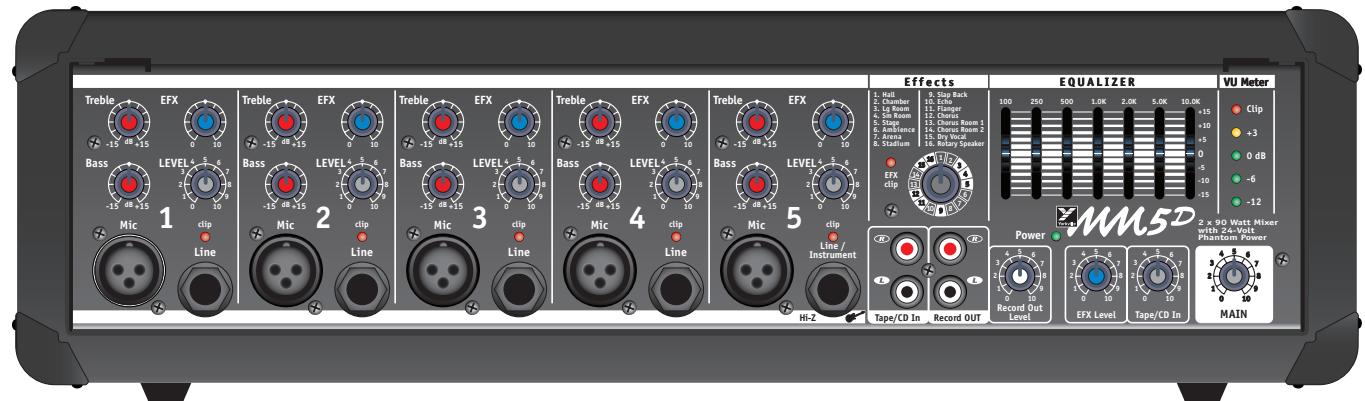
The MM5D features XLR low-impedance microphone connectors on the channels. These microphone inputs are balanced for maximum noise suppression. The 24 Volt DC phantom power is present on all 5 XLR input jacks for condenser microphones.
Note: You can use condenser and dynamic microphones with the phantom power present on the input XLR jacks. It will not affect the performance of the dynamic microphones.
In addition to the XLR inputs, each channel features 14 -inch LINE in phone jacks. Channels 1-4 are balanced line-level inputs and will accept either balanced (Tip/Ring/ Sleeve) or unbalanced (Tip/Sleeve) input cables from high impedance microphones, mixer line outputs, keyboards, synthesizers, electric pianos etc.
Note: When connecting a balanced signal, use balanced patch cables with either an XLR or a Tip/Ring/Sleeve 1/4 -inch phone plug on the mixer end.
Channel 5 has a very high impedance, unbalanced 14 -inch phone input which is optimized for instruments such as electric basses, acoustic electric guitars etc.
Connecting signals to both types of inputs on any one channel (MIC and LINE in) is not recommended. To do so may change the gain of the input circuit.
2. Channel LEVEL Controls and CLIP LEDs
The CHANNEL LEVEL control adjusts the signal level sent to the MAIN mixing bus. The CLIP LED will illuminate when the channel's overall signal level in that channel is 3 dB below the onset of actual clipping. As a result, small amounts of clip LED activity is acceptable, however frequent or continuous activity indicates the need to turn down the LEVEL control.
In audio terminology, the MAIN mixing bus is an audio signal path where all the signals from the input channels are blended into one signal. The MM5D has 2 busses: MAIN (left and right), and RECORD OUT.
3. Channel Lo, and Hi Equalization
The MM5D tone controls adjust the bass, and treble frequencies for each channel independently. Center frequencies have been carefully selected to help achieve the best quality of sound. BASS is centered on 80Hz , and the TREBLE is at 12kHz . The adjustment range for each control is +/- 15 dB. As with equalizers, boosting one or more frequencies increase the channel's level. If the channel is already at a high level, clipping may occur, in which case the clip LED will illuminate. Reduce the CHANNEL LEVEL setting and/or the CHANNEL Equalizer setting if clip LED activity is excessive.
Note: The EQ center position reflects a neutral or flat EQ control setting; however, turning down EQ settings can be used effectively to reduce feedback, and/or clean up the sound).
4. Channel EFX Controls
The EFX control (effects send) for each channel adjusts the level of the channel signal sent to the MM5D effects bus. This signal is post-LEVEL control and post-EQ, so the sound is affected by both the CHANNEL EQ controls and the CHANNEL LEVEL control. The signal from the CHANNEL EFX controls is internally routed to the Digital Effects Processor. The CHANNEL EFX control adjusts the intensity of the built-in digital effects for the channel's output.
Master Section
1. MAIN Control
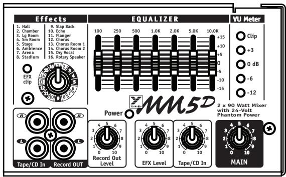
The MAIN control adjusts the overall level of the main mix, the PA volume.
Note: To ensure maximum signal headroom and clarity, first set the MAIN level control to 7, then set the channel LEVEL controls for a good signal without clipping, then go back to the MAIN level control and adjust for the overall volume desired.
2. MAIN EFFECTS Level Control
The MAIN EFX control adjusts the amount of signal from the output of the internal Digital Effects Processor to the MAIN mixing bus where it is mixed with the audio signal from the CHANNEL LEVEL controls. The MAIN EFX control adjusts the intensity of the effects on the left and right MAIN output signals.
3. Record OUT Jacks
The Record OUT audio signal at the Record OUT RCA jacks is the MAIN audio signal from channels 1 to 5, but without DIGITAL EFFECTS, and pre-GRAPHIC EQUALIZER. The Record OUT level control, located to the left of the MAIN control, adjusts the audio signal level going to these jacks. Using RCA patch cords, connect directly to the inputs (line-level) of an audio recording device.
4. Power LED and VU-Meter LED Display
The Power LED lets you know that the MM5D is plugged in, turned on and all systems are normal. The VU-Meter LEDs indicate the level of the audio signal going to the internal power amplifiers. The 0dB VU-Meter LED indicates when the amplifiers are delivering full power. Because there is an audio limiter on the input of each power amplifier, you can turn up the MAIN level control until the VU-Meter Clip LED illuminates where the audio limiter is at maximum compression. For maximum audio power output the MM5D sounds the best if the +3dB VU-Meter LED is illuminated but the VU-Meter Clip LED does not illuminate.
5. Phantom Power
Regular dynamic microphones can be used with the Phantom Powered XLR Channel inputs. Connecting a dynamic or condenser microphone to the MM5D when the MM5D's power is on will create a loud, potentially damaging pop in the loudspeakers. When setting up, turn off the MM5D's AC power, connect all of your microphones then turn the MM5D power on.
6. Tape/CD Input
There are left and right RCA inputs jacks on the front panel to connect a CD player, cassette player, MP3 player, or other stereo source to the mixer. These inputs connect directly to the MAIN bus, and to the Record OUT bus. The Tape/CD level control adjusts the input level of the audio signal.

1/4-inch Phone Plug

1/4-inch T.R.S. Phone Plug

XLR Plug

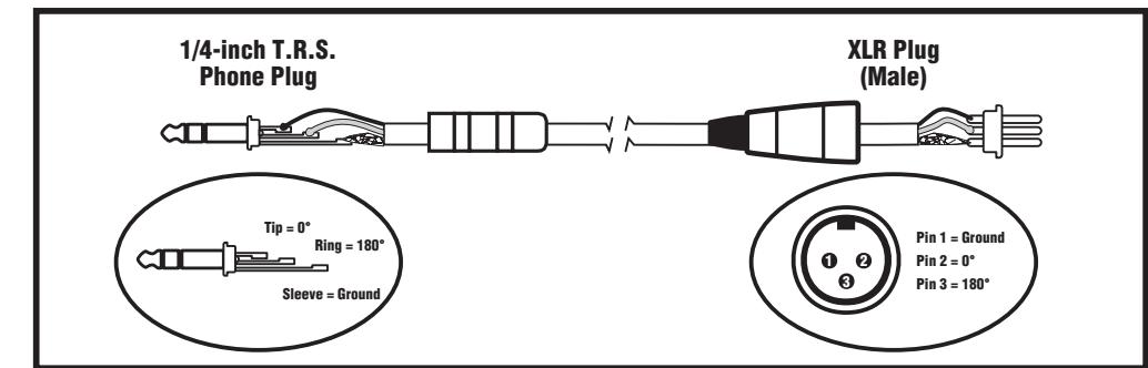
Balanced 1/4-inch T.R.S. to Balanced XLR
Digital Effects Processor
1. Select EFX Control
Use the EFX Selection control to choose from the sixteen 24-bit digital reversals, delays and other effects. This control rotates continuously, which lets you rotate clockwise or counter-clockwise to select the desired effect. For convenience, a table of the effects and their variables appear later in this manual and on the front panel of the MM5D.
2. Effects Clip LED
Situated to the left of the MODIFY EFX control, the CLIP LED indicates that the digital processor is receiving an input signal that is too large, resulting in distortion. For optimum performance, the CLIP LED should never flash. If there is clipping activity, turn down the channel EFX level controls appropriately.
Effects
- Hall
- Chamber
- Lg Room 4.Sm Room
- Stage
- Ambience 7.Arena
- Athena
-
Stadium
-
Slap Back
- Echo
- Flanger
- Chorus
- Chorus Room 1
- Chorus Room 2
- Dru Vocal
- Dl y vocal 16. Rotary Speaker

EFX clip


3. Effects Tables
See rear inside cover for the Digital Effects table.

EQUALIZER
Built in 7-Band Graphic Equalizer
1. General
The GRAPHIC EQUALIZER consists of seven +/-15dB range type controls. The 100Hz, and 250 Hz controls adjust the bass region of the music (bass guitar, kick drum). The 500Hz, 1kHz, and 2kHz controls adjust the midrange region of the music (vocals, keyboards, guitars). The last two controls 5kHz, and 10kHz adjust the treble region of the music (drum cymbals, and overall brightness).
Note: Equalizers have an effect on the gain of the main system as well as its frequency response. Once adjusted, you may need to adjust the MAIN level control if the VU-Meter Clip LED flashes.
2. Reducing Feedback with the Graphic EQ
A technique used to help reduce feedback uses the GRAPHIC EQUALIZER. Turn the MAIN level control up to the point of feedback and watch for one of the LEDs located on the end of the GRAPHIC EQUALIZER sliders to turn on. When the specific slider LED turns on, slide the slider down to about -3 to -5 dB. Usually only 2 or 3 bands can be reduced before the feedback reduction process begins to affect the sound quality. If this occurs move the microphones away from the loudspeakers, and turn down the CHANNEL LEVEL of any microphones not used by performers at that time.
MM5D Rear Panel
1. Power Amplifiers
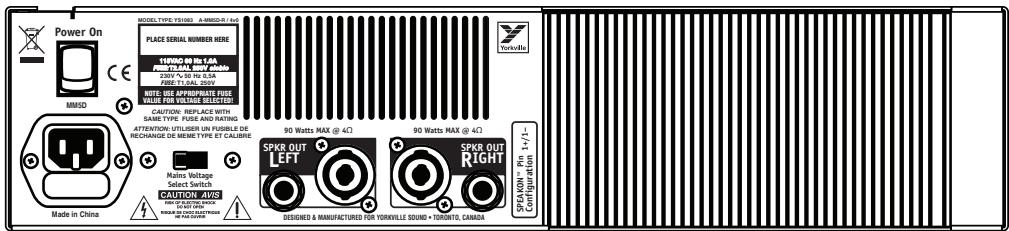
Each channel of the MM5D's power amplifiers has a 14 -inch phone jack and a Speakon jack for speaker connections. The power amplifiers are designed to provide full power into a 4-ohm load. When speaker impedances lower than 4 ohms are connected, the amplifier will go into PROTECT for six seconds, then test the speaker load with the audio signal. If the speaker load is 4 ohms or higher the amplifier will return to normal operation. If the speaker load is still less than 4 ohms the amplifier will go into PROTECT again for another six seconds, then test the speaker load with the audio signal.
The heat sink fins on the rear of the MM5D are adequate to cool the amplifier for 8 ohm loudspeaker loads. If 4 ohm loudspeakers are used an internal fan may turn on to keep the amplifier cool. The MM5D has more thermal capacity than any other equivalent small box mixer.
WARNING: Do not obstruct the flow of air around the heat sink fins and the chassis vents on the rear of the MM5D, as this may cause the power amplifier to overheat. If the power amplifier overheats the amplifier will turn off the audio signal to protect itself. After the MM5D cools down, operation will be restored automatically. This condition should not occur if adequate ventilation is provided at the back of the unit.
2. Power Switch, Fuse, and Mains Voltage Selector
The Power switch, mains fuse, and mains voltage selector are located on the rear panel. The fuse is located in the 115 volt / 230 volt power connector. If the fuse burns open during use, replace it with the same value and type of fuse. Please note that a different value of fuse must be used for 230 volt operation. If after replacing the fuse the fuse burns open again, take the unit to your Yorkville dealer for service. To select the mains voltage for the MM5D first remove the power cord from the MM5D. Now loosen do not remove the two screws holding on the clear cover over the mains voltage selector switch. Rotate the clear cover to access the mains voltage selector switch. Adjust the switch to 115VAC or 230VAC. You must know the mains voltage for your region in your country. Ask someone before setting the switch to the wrong position and damaging your MM5D. Now slide the clear cover over the screw and tighten the screws.


General Operating Instructions
- Connect the AC power cord to a 120 Volt AC grounded power outlet (230 to 245 Volts in export units).
- Turn the CHANNEL level controls, EFX level controls, Record, and Tape/CD level controls, and MAIN master level control to 0 initially.
- Now connect low-impedance microphones to the 3-pin XLR type MIC inputs.
- Connect high-impedance microphones or mono line-level signal sources (mixer line outputs, keyboards etc.), to the 14 -inch balanced LINE IN phone jacks on channels 1-5. Connecting more than one signal source to both XLR and 14 -inch phone inputs is not recommended; this includes stereo sources (if you try to connect a stereo source to a mono channel using a Y-adapter, you may get distortion). The 14 -inch phone input on channels 5 is optimized for musical instruments and is not balanced.
- Connect a stereo source (CD player, tape deck, stereo keyboard, MP3 player etc.) to the Tape/CD In jacks. Use shielded patch cords for all pre-amp connections.
- We recommend using 18-gauge speaker cables, using shielded patch cords to connect speakers will waste power by heating up. Connect one or two 8-ohm PA speakers or one 4-ohm speaker to each SPEAKER output on the rear panel.

Note: Two 8 ohm speakers can connect to each amplifier output. Connect the first speaker to the MM5D speaker output. Run a speaker wire from the first speaker to the second speaker. Using this method four 8 ohm speakers can connect to a MM5D (two per channel). Two of the 8 ohm speakers can face the audience and two 8 ohm speakers can be used as floor monitors for the performer.
- Position your main PA speakers at the front of the stage, pointing directly at the audience. If you have them position your monitor speakers on the stage floor, preferably to one side of the microphone stands, pointing up at the performer. Try to use cardioid or uni-directional microphones to help reduce the threat of feedback through the monitors (avoid having the back of the microphone pointing directly at the speakers).
- During a sound check and with the band playing or performer speaking make the following control adjustments:
i. Set the MAIN level control to 7 to start. Set the GRAPHIC EQUALIZER to 0. Set the CHANNEL BASS and TREBLE controls to the 12 o'clock position. Turn all EFX level controls to 0.
ii. On mono channels, you need to set the CHANNEL LEVEL appropriately. When using microphones for vocals the pointer of the CHANNEL LEVEL control knob should be set between 6 and 9 on the graphic around the CHANNEL LEVEL control knob. At this point you can turn the MAIN level control up or down to adjust the overall sound level coming from the loudspeakers. For inputs plugged into the channel phone jack you should set the CHANNEL LEVEL between 1 and 9 on the graphic around the CHANNEL LEVEL control knob. Channel 5's phone input is tailored for guitars with pickups that plug into the mixer. It is best to set the gain on the guitar to the mid position for best headroom and lowest noise level.
iii. Now you can adjust he CHANNEL BASS and TREBLE controls for a better sound for each channel.
iv. Turn up the EFX controls on those channels requiring the selected Digital Effect. Typically, the lead and harmony vocal channels would be good candidates for effects. Reverb can be used on other channels for other instruments, but should be used sparingly.
- Feedback during a performance is usually caused by one of the stage monitors positioned too close to a microphone or sound from the main speaker reflecting through the room back into the microphones. If feedback occurs, try the following procedures:
i. Direct the floor monitor speakers away from the microphones.
ii. Use the GRAPHIC EQUALIZER to reduce feedback. Without the music playing turn the MAIN level control up to the point of feedback and watch for one of the LEDs located on the end of the GRAPHIC EQUALIZER sliders to turn on. When the specific slider LED turns on, slide the slider down to about -3 to -5 dB. Usually only 2 or 3 bands can be reduced before the feedback reduction process begins to affect the sound quality. If this occurs move the microphones away from the monitor and main loudspeakers, and turn down the channel gain level of any microphones that are not used by performers. Using the graphic equalizer with small adjustment to reduce feedback will also improve the sound that your audience will hear as reducing feedback adjusts for room resonances which make your sound "boomy or pingy" to the listener
MM5D Digital Effects
- Hall - A long, warm reverb simulating the sound of a large concert hall. Good for guitars and vocals.
- Chamber - A medium decay reverb simulating the sound of a chamber. Good for pianos, guitars, and vocals.
- Lg Room - A short decay reverb, similar in sound to a large room with hard surfaces.
- Sm Room - A short decay reverb, similar in sound to a small room with hard surfaces.
- Stage - This is a simulation of a performing stage. An open space with a well damped decay.
- Ambience - A short multi-reflection reverb. Very much like a Plate reverb. Good for vocals and drums.
- Arena - A medium, open, and warm reverb. Good for vocals and instruments.
- Stadium - A long, open, and warm reverb. Good for vocals.
- Slap Back - A short 125ms delay. Good for guitars and for thickening vocals.
- Echo - A warm echo that provides a couple of repeats.
- Flanger - A rhythmically shifting comb filter that constantly changes the tone of th music. Good for guitars.
- Chorus - Chorus is an electronic effect that takes multiples your original music signal and staggers each copy in time and pitch, similar to what happens when a choir sings. This is a dry Chorus without reverb.
- Chorus Room 1 - Very much like effect 12 but a small room with a short reverb decay.
- Chorus Room 2 - Very much like effect 13 but a medium room with a short reverb decay.
- Dry Vocal - A very tight small space effect. Good for close vocals.
- Rotary Speaker - Great with keyboards, this is a recreation of an effect originally popular with organ players. The sound of a spinning speaker is akin to a tremolo with Doppler pitch shifting.
Specifications
Model: MM5D Powered Box Mixer
Model ID: MM5D
Number of Channels: 5
Mono Channel EQ: 2-band shelving
Channel Effects: Yes
Inputs - XLR (bal): Ch. 1-5
Inputs - 1/4-inch: Ch. 1-5
Inputs - RCA (unbal): Tape/CD in
Internal Effects: 16 Digital Effects: reverb, echo, chorus, flange
External Effects Send: no
External Effects Return: no
Effects Return to Main: Yes
Record Outputs RCA (unbal): Record Out with Level Control
Max Gain to Amplifier Out-Mic Input (dB): 84
Max Gain to Amplifier Out -Line Input (dB): 70
Main Outputs (Line Level): n.a.
Outputs - Amp A/B - Speakon / 1/4-inch Jacks: 1/1
Mixer - Frequency Response (Tone and EQ Flat, +/-2dB): 40-20000 Hz
Amp A/B - Power Output @ 8 Ohms (0.1% THD, 1kHz): 2 x 60 watts
Amp A/B - Power Output @ 4 ohms: 2 × 90 watts
THD - 20Hz-20kHz (dB): less than 0.1%
Power Consumption (typ/max): 1.0 A @ 120VAC / 0.5 A @ 240VAC
Protection: Clip limiter, thermal shutdown
Cooling: Passive heatsink and internal Fan
Dimensions (DWH, inches): 9x17.75x6
Dimensions (DWH, cm): 22.85x45x15.25
Weight (lbs/kg): 19.2 / 9.7

Introduction

Balanced 1/4-inch T.R.S. to Balanced XLR
- Hall
- Chamber
- Lq Room
- Sm Room
- Stage
- Ambience
7.Arena -
Stadium
-
Slap Back
- Echo
- Flanger
- Chorus
- Chorus Room 1
- Chorus Room 2
- Dry Vocal
- Rotary Speaker


3. Tables Des Effects
Dimensions (PLH, pouces): 9x17.75x6
Dimensions (PLH, cm): 22.85x45x15.25
Poids (livres/kg): 19.2 / 9.7

00000000000000000000
Aeepnneepnnnneep
Unlimited Warranty
Yorkville's two and ten-year unlimited warranty on this product is transferable and does not require registration with Yorkville Sound or your dealer. If this product should fail for any reason within two years of the original purchase date (ten years for the wooden enclosure), simply return it to your Yorkville dealer with original proof of purchase and it will be repaired free of charge. This includes all Yorkville products, except for the YSM Series studio monitors, Coliseum Mini Series and TX Series Loudspeakers.
Freight charges, consequential damages, weather damage, damage as a result of improper installation, damages due to exposure to extreme humidity, accident or natural disaster are excluded under the terms of this warranty. Warranty does not cover consumables such as vacuum tubes or par bulbs. See your Yorkville dealer for more details. Warranty valid only in Canada and the United States.
Garantie Illimitée
Voice: (716) 297-2920
Fax: (716) 297-3689

WEB: www.yorkville.com
Niagara Falls, New York
14305 USA
Voice: (716) 297-2920
Fax: (716) 297-3689

- OWNER'S MANUAL MANUEL DE L'UTILISATEUR
- IMPORTANT SAFETY INSTRUCTIONS
- CAUTION: TO REDUCE THE RISK OF ELECTRIC SHOCK, DO NOT REMOVE COVER (OR BACK).
- Power Sources
- Hazards
- Power Cord
- Service
- SUVEZ TOUTES LES INSTRUCTIONS
- Stereo Power Amplifier
- Input Wiring tips:
- Input Channels
- MIC and LINE Inputs
- Channel LEVEL Controls and CLIP LEDs
- Channel Lo, and Hi Equalization
- Channel EFX Controls
- Master Section
- MAIN Control
- MAIN EFFECTS Level Control
- Record OUT Jacks
- Power LED and VU-Meter LED Display
- Phantom Power
- Tape/CD Input
- Digital Effects Processor
- Select EFX Control
- Effects Clip LED
- Effects
- Effects Tables
- Built in 7-Band Graphic Equalizer
- General
- Reducing Feedback with the Graphic EQ
- MM5D Rear Panel
- Power Amplifiers
- Power Switch, Fuse, and Mains Voltage Selector
- General Operating Instructions
- MM5D Digital Effects
- Specifications
- Introduction
- Tables Des Effects
- Unlimited Warranty
- Garantie Illimitée
Brand : YORKVILLE
Model : MM5D
Category : Studio Monitor