
CR12 - Passive speaker YORKVILLE - Free user manual and instructions
Find the device manual for free CR12 YORKVILLE in PDF.


| Product type | Power Amplifier |
| Brand | YORKVILLE |
| Model | CR12 |
| Continuous Output Power | 380 W/channel at 8 Ω, 575 W/channel at 4 Ω, 1150 W bridged at 8 Ω |
| Burst Power | 475 W/channel at 8 Ω, 760 W/channel at 4 Ω, 1550 W bridged at 8 Ω |
| Frequency Response | 30 Hz - 20 kHz (±1 dB) |
| Distortion (THD) | < 0.01% (typical, 1 kHz, 4 Ω) |
| Input Impedance | 20 kΩ balanced, 10 kΩ unbalanced |
| Input Sensitivity | 1.4 V RMS (gain 31 dB) |
| Signal-to-Noise Ratio | > 104 dB (unweighted) |
| Damping Factor | > 300 |
| Operating Modes | Stereo, Mono, Bridge |
| Input Connectors | XLR/Jack combo, screw terminal |
| Output Connectors | Heavy-duty binding posts (banana, spade, bare wire), 1/4" jack |
| Protection | Short circuit, thermal, DC offset |
| Limiter | Switchable, soft clip |
| Cooling | Two-speed fan |
| Power Supply | Mains, typical consumption 500 W, max 960 W |
| Dimensions (W x H x D) | 48 x 13 x 33 cm |
| Weight | 13.6 kg |
| Rack Mounting | 3U, standard 19-inch |
| Finish | Black baked enamel steel |
| Care and Cleaning | Dust regularly, avoid humidity, clean with a dry cloth |
| Safety | Unplug before maintenance, do not expose to water, use on a stable surface |
| Spare Parts and Repairability | Consult a qualified technician, no user-serviceable parts |
Frequently Asked Questions - CR12 YORKVILLE
User questions about CR12 YORKVILLE
0 question about this device. Answer the ones you know or ask your own.
Ask a new question about this device
Download the instructions for your Passive speaker in PDF format for free! Find your manual CR12 - YORKVILLE and take your electronic device back in hand. On this page are published all the documents necessary for the use of your device. CR12 by YORKVILLE.
USER MANUAL CR12 YORKVILLE
IMPORTANT SAFETY INSTRUCTIONS
CAUTION AVIS
RISK OF ELECTRIC SHOCK
DO NOT OPEN
RISQUE DE CHOC ELECTRIQUE
NE PAS OUVRIR

INSTRUCTIONS PERTAINING TO A RISK OF FIRE, ELECTRIC SHOCK, OR INJURY TO PERSONS.
CAUTION:
TO REDUCE THE RISK OF ELECTRIC SHOCK, DO
NOT REMOVE COVER (OR BACK).
NO USER SERVICEABLE PARTS INSIDE.
REFER SERVICING TO QUALIFIED
SERVICE PERSONNEL.
INSTRUCTIONS RELATIVES AU RISQUE DE FEU, CHOC ÉLECTRIQUE, OU BLESSURES AUX PERSONNES.
AVIS:
AFIN DE REDUIRE LES RISQUE DE CHOC ELECTRIQUE,
N'ENLEVEZ PAS LE COUVERT (OU LE PANNEAU
ARRIERE). NE CONTENT AUCUNE PIECE REPARABLE
PAR L'UTILISATEUR.
CONSULTEZ UN TECHNICIEN QUALIFIE
POUR L'ENTRETIENT.
Read Instructions:
The Owner's Manual should be read and understood before operation of your unit. Please, save these instructions for future reference.
Packaging:
Keep the box and packaging materials, in case the unit needs to be returned for service.
Warning:
When using electric products, basic precautions should always be followed, including the following:
Power Sources:
Your unit should be connected to a power source only of the voltage specified in the owners manual or as marked on the unit.
This unit has a polarized plug. Do not use with an extension cord or receptacle unless the plug can be fully inserted. Precautions should be taken so that the grounding scheme on the unit is not defeated.
Hazards:
Do not place this product on an unstable cart, stand, tripod, bracket or table. The product may fall, causing serious personal injury and serious damage to the product. Use only with cart, stand, tripod, bracket, or table recommended by the manufacturer or sold with the product. Follow the manufacturer's instructions when installing the product and use mounting accessories recommended by the manufacturer.
The apparatus should not be exposed to dripping or splashing water; no objects filled with liquids should be placed on the apparatus.
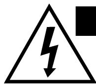
Terminals marked with the "lightning bolt" are hazardous live; the external wiring connected to these terminals require installation by an instructed person or the use of ready made leads or cords.
No naked flame sources, such as lighted candles, should be placed on the apparatus.
Power Cord:
The AC supply cord should be routed so that it is unlikely that it will be damaged. If the AC supply cord is damaged DO NOT
OPERATE THE UNIT.
Service:
The unit should be serviced only by qualified service personnel.
Your new CR12 power amplifier is designed and built to provide years of trouble free performance. Like all Yorkville Sound amplifiers, it's designed to be rugged and reliable in all applications. Generous output current capability, along with low distortion and high headroom performance, guarantee the sonic integrity of the CR12 power amplifier.
Since the CR12 has been designed and manufactured by Yorkville Sound, each unit undergoes rigorous Quality Assurance tests. Each circuit is tested by sophisticated computer controlled equipment (which is capable of identifying any deviation from the design center parameters). The final tests include a temperature cycled burn-in period.
INPUTS
Unbalanced Inputs
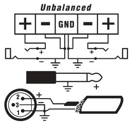
The Combi-jack and terminal strip can be used to connect an unbalanced signal to the CR12. Follow the directions in figure 2 & 3 for the various unbalanced connections. If possible, always use balanced cables, as they will reduce the possibility of noise entering the sound system. If unbalanced cables must be used, keep the length of the cable as short as possible, this should minimize the amount of noise entering the sound system.
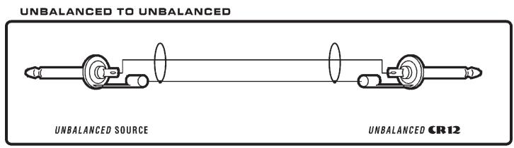
figure 2
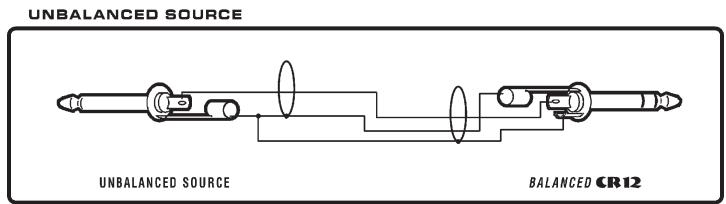
figure 3
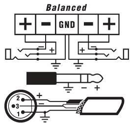
Balanced Inputs
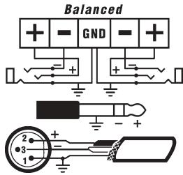
The CR12 has high quality balanced inputs with hum rejection. Three types of balanced input connectors are available. The Combi-jack input will accept a standard 1/4 inch TRS (stereo) phone plug or an XLR plug for balanced operation. The tip of the 1/4 inch TRS (stereo) phone plug and pin 2 of the XLR plug are the positive (hot) connections. A terminal strip input allows for a direct-wired connection for installation applications. Use a forked-lug for a #6 screw to connect the input wires to the barrier strip. Follow the directions in figure 4 & 5 (on the following page) for the various balanced connections. We recommend using balanced connections wherever possible to ensure that the sys-
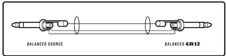
BALANCED (TRS) 1/4 TO BALANCED (TRS) 1/4
figure 4
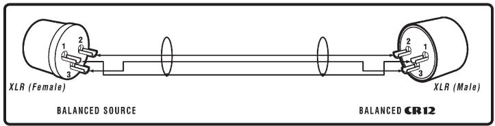
BALANCED (XLR) TO BALANCED (XLR)
figure 5
Speaker Configurations
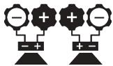
Mono or S

tem is noise free.
Mono Operation
The CR12 can also be operated in mono by switching the mode switch to mono and connecting the input signal to either the A or B input jack. This signal will be sent to both amplifiers. Each amplifier's audio level will be controlled by its corresponding gain control. You can use the remaining input jacks to "loop through" to another amplifier or a piece of sound equipment.
Stereo Operation
The CR12 may be operated in stereo by switching the mode switch to stereo and connecting the "Left / Right" stereo input signal to the A and B input jacks. Each gain control will adjust the audio level for its corresponding amplifier channel. The input jacks for each channel are wired in parallel so that the unused connector can be used to send the input signal to another amplifier or piece of sound equipment.
Bridged Operation
The CR12 may be operated in bridged mode by switching the mode switch to bridge and connecting the input signal to either the A or B input jack. Channel A's gain control is used to adjust the audio signal level. The loudspeaker load is connected across the two red binding posts with the positive lead of the loudspeaker wire connected to the red channel A binding post.
Outputs
Two types of output connectors are on the output of the CR12. Heavy-duty binding posts accept a banana plug, forked-lug or bare wire connections. When the amplifier is used in stereo (or mono mode), connect the loudspeaker to the red and black binding posts. With the positive wire, from the loudspeaker, connecting to the red binding post, and the negative wire to the black binding post. For bridged mode operation, the speaker load is connected across the two red binding posts with the positive lead of the speaker wire connected to the red channel (A) binding post. The diagrams on the sidebar show the different loudspeaker wiring configurations. The other connector is a 1/4 inch phone jack for quick setups and teardowns. Use a mono 1/4 inch phone plug with the tip of the plug wired to the positive connector and the sleeve of the phone plug wired to the negative connector of the loudspeaker.
Each channel of the CR12 delivers up to 575 watts per channel into a 4-ohm loudspeaker. Wiring two 8-ohm speakers to one channel will look like a 4-ohm loudspeaker to the amplifier and each 8-ohm loud-speaker will receive 287 watts. In bridge mode the CR12 drives up to 1150 watts into an 8-ohm loudspeaker.
Gain Controls
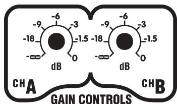
The CR12's gain controls are located on the back of the amplifier. This prevents tampering with the gain controls when the amplifier is rack mounted. The gain controls are calibrated in dB (decibels), corresponding to the audio voltage present at the speaker output jacks. Where many amplifiers are used in an installation, the gain controls scaled in dB allow the user to precisely set the audio output level of one CR12 amplifier channel relative to the other CR12 amplifier channels. This only works if the amplifiers are receiving the same amplitude of input audio signal. The 0 db, or "full" position, of the gain control refers to 48 volts RMS (which
equals 575 watts into 4-ohms) on the output of the amplifier when a 1.4 volt RMS voltage is present at the input jacks. Placing the gain control in the -3dB position with 1.4 volt RMS voltage present at the input jacks will result in a 34 volt signal (which equals 288 watts into 4-ohms) at the speaker output.
LIMITER

Limiter
The limiter switch located on the back panel of the amplifier enables the limiter. When the limiter switch is in the off position, at full power output the amplifier will clip the peaks of the music signal and the clip LED will illuminate. The music could sound distorted. When the limiter switch is in the on position the limiter acts more like a leveler. This allows the bass thumps in music to drive the output of the amplifier into clipping for the duration of the thump, but will not heavily clip a continuous signal like someone screaming into a microphone. This mode is useful for public address applications where the full headroom of the amplifier is utilized and the quality of the voice is maintained by using the soft clipping feature of the limiter.
Short Circuit Protection
The CR12 is fully protected against all possible passive loudspeaker load conditions. It can operate with a "dead" short continuously without damage (we don't recommend that you short your CR12 "just-for-fun"). Shorts create a lot of stress on the output devices. If a short is present on the output of the amplifier with a signal passing through the amplifier then the protect LED will illuminate and the amplifier will go into "sleep mode" turning off the audio signal passing through the amplifier. After 8 seconds, the amplifier will allow the signal to pass through the amplifier and check to see if the short has been removed. If the short is still present the amplifier will go through the sleep mode cycle again. If the short has been removed, the amplifier will continue to drive the speaker. The output protection will allow the output of the amplifier to drive a loudspeaker with up to 35 degrees of phase shift at 4-ohms.
Cooling & Thermal Protection
A two-speed fan cools the heatsinks of the amplifier. When the amplifier's heatsinks are cool the fan operates in low speed. When the amplifier is driving music into loudspeakers, and the heatsinks temperature rises above 45 degrees Celsius, the fan switches to high speed. After the heatsinks cool below 40 degrees Celsius the fan returns to low speed. When operating the CR12 care should be taken to allow cool air to enter the front of the amplifier and the hot air to exhaust out of the rear. The CR12 was designed to run cool under normal operating conditions, but restricting the airflow around or through the amplifier could cause the amplifier to thermally shutdown.
If the temperature on the heatsinks in the CR12 exceeds the safe operation temperature, the amplifier will shutdown illuminating both protection LED's and turn off the audio signal to the speaker output jacks until the heatsink temperature drops to a safe level.
Rack Mounting:
The CR12 was designed to mount into a standard 19-inch rack. Care must be taken to provide adequate ventilation around the amplifier and the rack itself should have adequate ventilation to the outside air. Leave the front and back of the rack as open as possible to allow the intake and exhaust air to flow in and out of the amplifier.
Clip / Protection LED's
The clip/protection LEDs on the front panel will blink to visibly indicate any signal excursion beyond the dynamic headroom of the amplifier. The clip/protection LEDs will remain on when the amplifier goes into its protection mode. The CR12 will go into protection for one of three reasons:
- the power switch of the amplifier has just been turned on or off.
- The amplifier has a shorted speaker load on the output of the amplifier.
- The temperature on the heatsinks of the CR12 exceeds the safe operation temperature.
Specifications
Continuous Power: (Both Channels Driven, 1 KHz, 0.1% THD)
8 ohms 380 Watts (x2)
4 ohms 575 Watts (x2)
2 ohms 400 Watts (x2)
8 ohms Bridged 1150 watts
4 ohms Bridged 800 watts
Burst Power: (Both channels driven, 10m Sec of 1KHz)
8 ohms 475 watts (x2)
4 ohms 760 watts (x2)
2 ohms 400 watts (x2)
8 ohms bridged 1550 watts
Frequency Response: ±1 dB 30Hz - 20 KHz
Hum and Noise: < -104 dB (unweighted)
Distortion: <0.01% THD (typ, 1 KHz 4 Ohms)
<0.15% THD (typ, 20 Hz - 20KHz, 4 ohms)
Slew Rate: >20 V/uSec
Damping Factor: >300
Input Impedance: 20 KOhms Balanced
10 KOhms Unbalanced
Input Sensitivity: 1.4 (31dB gain) VRMS Sine
Common Mode Rejection (CMRR): 48 dB minimum / 56 dB typical (at 60 Hz)
Modes: Stereo / Mono / Bridge
Power Consumption: 500 Watts (typ.), 960 W (max)
Protection: DC, Load, Thermal
Limiter: Defeatable Peak
Cooling: Two speed Fan
Input Connectors: Terminal Strip and XLR / 1/4inch Phone (TRS) Combi-Jack
Transformer: Toroidal
Rack Space: 3 Sp
Size: 33cm× 48cm× 13cm (DWH)
13 inches x 19 inches x 5.25 inches (DWH)
Exterior Finish: Baked, black painted steel
Weight: 30 lbs. 13.6 Kg
<0.15% THD (typ, 20 Hz - 20KHz, 4 Ohms)
Propagation: >20V / uSec
SOURCE ASYMétrIQUE
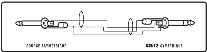
figure 3
Entrées Symétriques
Niagara Falls, New York
14305 USA
Voice: (716) 297-2920
Fax: (716) 297-3689

Quality and Innovation Since 1963
Printed in Canada

- IMPORTANT SAFETY INSTRUCTIONS
- CAUTION AVIS
- CAUTION
- AVIS
- READ INSTRUCTIONS
- PACKAGING
- WARNING
- POWER SOURCES
- HAZARDS
- POWER CORD
- OPERATE THE UNIT
- SERVICE
- INPUTS
- UNBALANCED INPUTS
- BALANCED INPUTS
- MONO OPERATION
- STEREO OPERATION
- BRIDGED OPERATION
- OUTPUTS
- GAIN CONTROLS
- LIMITER
- SHORT CIRCUIT PROTECTION
- COOLING & THERMAL PROTECTION
- RACK MOUNTING
- CLIP / PROTECTION LED'S
- SPECIFICATIONS
- ENTRÉES SYMÉTRIQUES
Brand : YORKVILLE
Model : CR12
Category : Passive speaker