
MPX 4500 - Audio Amplifier MAC AUDIO - Free user manual and instructions
Find the device manual for free MPX 4500 MAC AUDIO in PDF.
| Product type | 4-channel audio amplifier |
| Brand | MAC AUDIO |
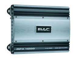
| Model | MPX 4500 |
| Maximum output power (4 Ohms, stereo) | 4 x 225 W |
| Maximum output power (4 Ohms, bridged) | 2 x 600 W |
| RMS power (4 Ohms, stereo) | 4 x 80 W |
| RMS power (4 Ohms, bridged) | 2 x 240 W |
| Maximum output power (2 Ohms, stereo) | 4 x 300 W |
| RMS power (2 Ohms, stereo) | 4 x 120 W |
| Speaker impedance (stereo) | 2 - 8 Ohms |
| Frequency response | 5 - 50 000 Hz (-3 dB) |
| Total harmonic distortion | < 0.05 % (1 kHz) |
| Crosstalk attenuation | > 60 dB (1 kHz) |
| Signal-to-noise ratio | > 100 dB (IEC A) |
| LOW LEVEL input sensitivity | 400 mV - 4 V |
| LOW LEVEL input impedance | 20 kOhms |
| Low-pass filter | 40 - 300 Hz, 12 dB/octave |
| High-pass filter | 40 - 300 Hz, 12 dB/octave |
| Bass Boost | 0...12 dB at 45 Hz |
| Power supply | 12 V (9 - 15 V), negative ground |
| Fuse | 2 x 20 A |
| Dimensions (W x H x D) | 319 x 59 x 226 mm |
| Weight | 2.75 kg |
| Features | Complementary final stages, automatic turn-on, adjustable filters, bridgeable 4/3/2-channel operation, Tri-mode, short-circuit protection, Line Out outputs |
| Warranty | 2 years for the first owner |
Frequently Asked Questions - MPX 4500 MAC AUDIO
User questions about MPX 4500 MAC AUDIO
0 question about this device. Answer the ones you know or ask your own.
Ask a new question about this device
Download the instructions for your Audio Amplifier in PDF format for free! Find your manual MPX 4500 - MAC AUDIO and take your electronic device back in hand. On this page are published all the documents necessary for the use of your device. MPX 4500 by MAC AUDIO.
USER MANUAL MPX 4500 MAC AUDIO
At the end of the product's useful life, please dispose of it at appropriate collection points provided in your country.
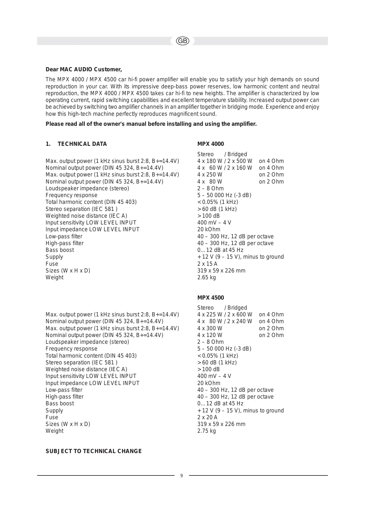
The MPX 4000 / MPX 4500 car hi-fi power amplifier will enable you to satisfy your high demands on sound reproduction in your car. With its impressive deep-bass power reserves, low harmonic content and neutral reproduction, the MPX 4000 / MPX 4500 takes car hi-fi to new heights. The amplifier is characterized by low operating current, rapid switching capabilities and excellent temperature stability. Increased output power can be achieved by switching two amplifier channels in an amplifier together in bridging mode. Experience and enjoy how this high-tech machine perfectly reproduces magnificent sound.
Please read all of the owner's manual before installing and using the amplifier.
1. TECHNICAL DATA
Max. output power (1 kHz sinus burst 2:8, B+=14.4V)
Nominal output power (DIN 45 324, B+=14.4V)
Max. output power (1 kHz sinus burst 2:8, B+=14.4V)
Nominal output power (DIN 45 324, B+=14.4V)
Loudspeaker impedance (stereo)
Frequency response
Total harmonic content (DIN 45 403)
Stereo separation (IEC 581)
Weighted noise distance (IEC A)
Input sensitivity LOW LEVEL INPUT
Input impedance LOW LEVEL INPUT
Low-pass filter
High-pass filter
Bass boost
Supply
Fuse
Weighted noise distance (IEC A)
Input sensitivity LOW LEVEL INPUT
Input impedance LOW LEVEL INPUT
Low-pass filter
High-pass filter
Bass boost
Supply
Fuse
Sizes (W x H x D)
Weight
MPX 4000
Stereo /Bridged
4 x 180 W / 2 x 500 W – on 4 Ohm
4 x 60 W / 2 x 160 W on 4 Ohm
4 x 250 W on 2 Ohm
4x 80W on2Ohm
2-8 Ohm
5-50 000 Hz (-3 dB)
< 0.05% (1 kHz)
60dB(1kHz)
100dB
400 mV - 4 V
20 kOhm
40 - 300 Hz, 12 dB per octave
40 - 300 Hz, 12 dB per octave
0...12 dB at 45 Hz
- 12 V (9 - 15 V), minus to ground
2 × 15 ~A
319 × 59 × 226 ~mm
2.65 kg
MPX 4500
Stereo /Bridged
4 x 225 W / 2 x 600 W on 4 Ohm
4x 80W/2x240W on 4 Ohm
4 x 300 W on 2 Ohm
4x120W on 2 Ohm
2-8 Ohm
5-50 000 Hz (-3 dB)
< 0.05% (1 kHz)
60dB(1kHz)
100dB
400 mV - 4 V
20 kOhm
40 - 300 Hz, 12 dB per octave
40 - 300 Hz, 12 dB per octave
0...12 dB at 45 Hz
- 12 V (9 - 15 V), minus to ground
2 × 20 ~A
319× 59× 226mm
2.75 kg
2. FEATURES
Complementary push-pull final stage
Automatic switching on/off via car radio
- Infinitely adjustable high pass and low pass filters
- Infinitely variable bass equalisation
Adjustable input sensitivity
Bridgeable 4-/3-/2-channel mode
Tri-mode
Electronic protective circuit against short circuiting, DC offset and excess temperature
Mute switch for suppressing switch-on crackle interference
Low-level outputs (cinch jacks) for connecting a subwoofer amplifier
- Status indicator (green LED) and overload indicator (red LED)
3. IMPORTANT INSTALLATION INFORMATION
This appliance may only be connected to a 12 volt system with negative ground.
The heat radiated when the amplifier is used means that sufficient air circulation is required at the place of installation. It is very important that the cooler's cooler ribs do not contact any metal plating or any surfaces which could impair air circulation. The amplifier may not be installed in small confined spaces or spaces without air circulation (e.g. spare wheel recess or under the vehicle carpeting). Installation in the boot is recommended.
Install the amplifier in such a way that it is protected as far as possible against vibrations and dust and dirt.
Make sure that the input/output cables are sufficiently distant from the power supply cables as otherwise interference may occur.
Make sure that the fuse and operating elements are accessible after installation.
The appliance's reliability and performance depend on the quality of installation. Preferably get an expert to install the system, particularly if you want to install several loudspeakers or a complex multi-way system.
4. CONNECTIONS
4.1 POWER SUPPLY AND AUTOMATIC SWITCHING ON
Important notice: Before commencing the installation, disconnect the plus terminals from the car battery in order to prevent short circuits.
The power cabling usually installed in on-board car networks is not sufficient for a power amplifier's demands. Make sure that the power lines to GND and to the +12V terminal have been sufficiently specified. A cable cross-section of at least 12mm^2 must be used to connect the battery to the amplifier's terminals.
First connect the amplifier's GND terminal to the battery's minus pole. It is very important that the connection is good. Dirt residues must be carefully removed from the battery's connection point. A loose connection may cause malfunctions or interference noise or distortion.
The +12V amplifier connection must then be connected with a power cable possessing an integrated fuse to the battery's plus pole. The fuse should be located close to the battery; for safety reasons, the cable from the positive terminal of the battery to the fuse must not exceed 60~cm in length. Only insert the fuse when all installation work, including the connection of the loudspeakers, has been completed.
Now connect the car hi-fi receiver's remote control connection to the amplifier's REM control jack. A cable with a cross-section of 0.75mm^2 is sufficient for connecting the amplifier's REMOTE connection and the control device.
4.2 AUDIO CABLES
When installing the audio cable between the cinch output of your car receiver and the cinch input of the amplifier inside your car, the audio and power supply cables should, wherever possible, not be routed along the same side of the vehicle. We recommend an isolated installation, e.g. routing the power cable through the cable duct on the left-hand side and the audio cable through the cable duct on the right-hand side or vice versa. This reduces interference due to crosstalk into the audio cables.
4.3 LOUDSPEAKER CONNECTIONS
In normal operating mode (i.e. one loudspeaker on each individual amplifier channel), the lowest terminal resistance is 2 ohm per channel.
In bridging mode (two amplifier outputs combined) the lowest terminal resistance doubles to 4 ohm.
The impedance in tri-mode may not fall below 2 ohm per channel.
- Never connect the loudspeakers' minus terminals to the vehicle chassis.
- Never connect the +12 ~V supply voltage to a loudspeaker output as this would destroy the amplifier final stage.
If the amplifier is operated with lower terminal resistances or incorrectly used as described above, both the amplifier and the loudspeakers may be damaged. The warranty becomes void in such cases.
5. OPERATING ELEMENTS AND IN/OUTPUTS
5.1 SETTING THE INPUT SENSITIVITY
The input sensitivity may be adapted to any car radio or tape deck. Turn the volume control of your radio to its central position and then adjust the input-level controls (3) and (4) to produce an average medium volume. This setting usually provides sufficient power reserves at optimum weighted noise voltage.
ATTENTION: only reproduce loud test noises briefly to prevent damaging the loudspeakers.
5.2 LOW-PASS FILTER WITH ADJUSTABLE CROSS-OVER FREQUENCY
If the amplifier is used as a subwoofer amplifier, set the switch (9)/(10) to "LPF". Set the desired cross-over frequency using the control (7)/(8). This makes the filter adaptable to the installed woofer's sound requirements. The filter's high edge steepness is responsible for the precision reduction of medium and high frequency ranges.
5.3 HIGH-PASS FILTER WITH ADJUSTABLE CROSS-OVER FREQUENCY
If the amplifier is to be used as an amplifier for satellite loudspeakers (mid-range/tweeter loudspeakers), set switch (9)/(10) to "HPF". Set the desired cross-over frequency using the control (11)/(12). Only the frequencies above the set cross-over frequency will then be amplified. This effectively minimizes distortions caused by excessive membrane movement at low frequencies and small satellite loudspeakers without reducing the bass level.
5.4 BASS-BOOST
The bass-boost function (5/6) is used to increase or equalize the lower bass frequencies.
5.5 OUTPUTS FOR CONNECTING ADDITIONAL AMPLIFIERS
The input signal of the LINE INPUT connections CH1, CH2, CH3, CH4 (1 and 2, Fig. 7) is accumulated and forwarded directly to the LINE OUT (14) jacks. The LINE OUT connections allow the use of a subwoofer amplifier without requiring additional T-plugs and cables.
FIG. 1 POWER SUPPLY / REMOTE SWITCH-ON CONNECTIONS
(1) GND terminal for the ground, to the battery's minus pole
(2) REM terminal for remote switch-on
(3) Terminal for +12V battery voltage
(4) Battery
(5) Cable fuse
(6) To your car radio's automatic aerial connection
If your car is not equipped with an automatic aerial connection, connect this cable's plus pole (+) to the ignition lock. An on/off switch should be inserted in this case. Make sure that this switch is switched off if the amplifier is not used.
FIG.2 4-CHANNEL MODE
Connect and set the amplifier as shown in Fig. 2 if it is to be controlled by a car radio with four output channels and used with four loudspeakers:
(1) To the car radio, front left output
(2) To the car radio, front right output
(3) To the car radio, rear left output
(4) To the car radio, rear right output
(5) Front left loudspeaker
(6) Front right loudspeaker
(7) Rear left loudspeaker
(8) Rear right loudspeaker
FIG. 3/4 3-CHANNEL MODE
The 3-channel mode uses the high-pass filter for channels 1/2 and the low-pass filter for Channels 3/4. Section 5 describes how they are used.
FIG. 3
Connect and set the amplifier as shown in Fig. 3 if it is to be controlled by a car radio with stereo output and used with stereo satellite loudspeakers and a subwoofer.
(1) To the car radio, left output
(2) To the car radio, right output
(3) Left satellite loudspeaker
(4) Right satellite loudspeaker
(5) Subwoofer
FIG. 4
Connect and set the amplifier as shown in Fig. 4 if it is to be controlled by a car radio with stereo receiver and separate subwoofer output and used with stereo satellite loudspeakers and a subwoofer.
(1) To the car radio, left output
(2) To the car radio, right output
(3) To the car radio, subwoofer output
(4) Left satellite loudspeaker
(5) Right satellite loudspeaker
(6) Subwoofer
FIG.5 2-CHANNEL MODE
If the amplifier has to generate more power to operate two subwoofoers, connect and set it as shown in Fig. 5. The use of the low-pass filter used is described in Chapter 5.
(1) To the car radio, left output
(2) To the car radio, right output
(3) Subwoofer
(4) Subwoofer
FIG. 6 USE AS AN AMPLIFIER FOR 4 SATELLITE LOUDSPEAKERS AND A SUBWOOFER USING AN ADDITIONAL 1-CHANNEL AMPLIFIER (MPX MONO)
(1) To the car radio, front left output
(2) To the car radio, front right output
(3) To the car radio, rear left output
(4) To the car radio, rear right output
(5) Front left loudspeaker
(6) Front right loudspeaker
(7) Rear left loudspeaker
(8) Rear right loudspeaker
(9) Subwoofer
FIG. 7 OPERATING ELEMENTS AND IN/OUTPUTS
(1) Low-level inputs (channel 1/2, front)
(2) Low-level inputs (channel 3/4, rear)
(3) Input-level control channel 1/2
(4) Input-level control channel 3/4
(5) Bass-booster control (channel 1/2, front)
(6) Bass-booster control (channel 3/4, rear)
(7) FULL / LPF (low pass filter) / (HPF) high pass filter option switch for channel 1/2
(8) FULL / LPF (low pass filter) / (HPF) high pass filter option switch for channel 3/4
(9) Low-pass selector ON/OFF for channel 1/2
(10) Low-pass selector ON/OFF for channel 3/4
(11) Cross-over frequency control for the high pass (channel 1/2)
(12) Cross-over frequency control for the high pass (channel 3/4)
(13) Channel mode selector switch
(14) Low level outputs (Compound signal from CH1, CH2, CH3 and CH4)
Cher client de MAC AUDIO,
Contips:
- Converting a function f(x) to a function g(x) is a useful way of converting a function f(x) to a function g(x) .
- The term f(x) and g(x) are not the same.
- The term f(x) and g(x) means the same thing.
- The term f(x) and g(x) means different things.
5.5 SALIDAS PARA LA CONEXION DE AMPLIFICADORES ADICIONALES
4.3 HÖGTALARANSLUTNINGAR
Ybaxaembl nokynatelb MAC AUDIOa,
npno6peHne yCnHnTeJMoUHocTn DnA BtOMo6nJ C BbICOKKaueCTBeHHbIM BOCpOn3BedeHnem 3Byka MPX 4000 / MPX 4500 daet Bam Bo3MOxHocTb yDObNeTBopntb Baun BbICouaHnne Tpe6oBaHnK BOCpOn3BedeHnIO 3Byka B aBTOMo6nIe HauNyuShmM o6pa3om. MPX 4000 / MPX 4500 OTKpbIbAet HOBbie Ropn3OHTbl KaueCTBa BbICOKOTOHOr BOcPOn3BedeHnE 3Byka B aBTOMo6nIe; He3aBvCSmoOTTO, nDet IIN peYb O BnEaTlJaIOSeM pe3epBe MoUHocTn Hn3KnX YAcTOT, O Hn3KOM Ko3ΦΦuIeHne The HnInHeHbIX NCKaKeHn IN O HeNTpaHbOM BOCpOn3BedeHn. YcNlTeJb OTNuayEtCn Hn3KIM TOKOM BO36yJDeHn, CNOC6HOCTbIO 6bICTporo NepeKJIooHEnr N OTNuHOB TemNepaTyHoN CTaBbHocTbIO. PyTEm COBMeCTHO BKNIOUeHn IAByx KAHaONy UcNlTeJRA K ODNHY McNITeHb B pExKIme NepEMbIK MoKET 6bIT DoCTNIHyTa UnyuHenHa DNHAMkA B CoedINHeHN C 6OJee BbICOKB bIXODHO MOUHOCTbIO. IpOuyBCTByte, kaoe BeNikOlenHoe BOCpRnTne 3Byka B COBepSeHcTBe MoKET ObecneuHTb Bam 3TO yCTPOBJCTBO, CO3DaAHHOe NO COBpeMeHHoTHexHOLOrnn. Mbl JeNaem Bam orpOMHOrO yDOBoJIbCTBn!
Ipejde Yem Haatab yctaHOBky ycunnteYn BBecTn erO B 3KcNpyaTaunIO, npouHTaTe, noKaJyIcTa, pyKOBOCTBO nO yCTaHOBKe do KOHca.
1. TEXHNUECKNE DAHHbIE
MaKc. BbXoHna MoUHocTb (1 Kfζ Sinus Burst 2:8, B+=14,4B)
HominhaBna BbIXoHa MaOuHocTb (DIN 45 324, E+=14,4B)
MaKc. BbIXoHna MoUHocTb (1 KfC Sinus Burst 2:8, B + = 14,4B
HOMHaJIbHaB YbIXoHaJ MoUHocTb (DIN 45 324, B+=14,4B)
Полhoe conpoTnBJIeHne rPOMKOrOBoPurTeIa (Ctepeo)
Yactotha xapaKtepcntka
O6uŋ Ko3ΦΦnμeHT HeJIHeHbIX NcKaKeHn (DIN 45 403)
PepexoHoe 3aTyxHaHne (IEC 581)
OTHOseHne cnHn/um (IEC A)
UyBCTBnteIbHOCTb Ha BxOe LOW LEVEL INPUT
Bxodhoe noJHoe conpoTnBJIeHne LOW LEVEL INPUT
ΦιMbTp HIXKHX YactOT
ФильтВерхнхЧаТOT
YcJIeHHe Hn3Knx YactOT (Bass-Boost)
Питанne
PpeoXpaHnteIb
Pa3Mepbl (UxBxΓ)
Bec
MPX 4000
Ctepeo /yepe3 nepeMbIyKy
4x180BT/2x500BT K4OM
4x 60BT/2x160BT K4OM
4x250BT 2OM
4x 80BT K2OM
2-8OM
5-50000Γu(-3ДБ)
<0,05% (1 kΓι)
60ДБ(1KΓι)
100d6
400MB-4B
20 kOM
40-300Γu,12ДБ ha OKtaby
40-300Γu,12ДБHa OKTaBy
0...12ДБпрn45Γu
+12V(9-15V),MnHycHaMacce
2 × 15 A
319 × 59 × 226 MM
2.65K
MaKc. BbIXoHna MoUHocTb (1 KfU Sinus Burst 2:8, B + = 14,4B
HOMHaJIbHaBbIXoHaHaMoUHocTb(DIN45324,B+=14,4B)
MaKc. BbIXoHna MoUHocTb (1 KfC Sinus Burst 2:8, B + = 14,4B
HOMHaJIbHaB BbIXoJHa MoUHocTb (DIN 45 324, B+=14,4B)
Полhoe conpoTnBJIeHne rpoMkoROBOpuTeJia (cTepeo)
Yactotha xapaKTepeNtika
O6uŋ Ko3ΦΦnμeHT HeIINHeHbIX NcKaKeHn (DIN 45 403)
PepexoHoe 3aTyxAHne (IEC 581)
OTHOSEHNE cHnA/WM (IEC A)
UyBCTBnTeJIbHOCTb Ha BxOJe LOW LEVEL INPUT
Bxodhoe noJHoe cOpotnBJeHne LOW LEVEL INPUT
ΦHJIbTp HIXKHX ZaCTOT
ΦnJIbTp BepxHnx YactOT
YcJIeHHe Hn3Knx YactOT (Bass-Boost)
Питане
PpeoXpaHnteIb
Pa3Mepbl (UxBxΓ)
Bec
MPX 4500
Ctepeo /yepe3 nepeMbIky
4x225B/2x600BT K4OM
4x 80BT/2x240BT K4OM
4×300BT K2OM
4x120BT 2OM
2-8OM
5-50000Γu(-3πB)
<0,05% (1 kΓι)
60ДБ(1KΓι)
100d6
400MB-4B
20 kOM
40-300Γu,12ДБHa OKTaBy
40-300Γu,12ДБ ha OKТаВу
0...12ДБпр45Гц
+12V(9-15V),MnHycHaMacce
2 × 20 ~A
319 × 59 × 226 MM
2,75 K
2.OCOSEHHHOCTN
-Дононтеловий ДыBYТаКТьг БвIXОДНКAKKaI
- ABTomatUcheCKoe BKJIIOueHHe/ByIKJIIOueHHe uepe3 aBTOpaIIOnpMnIK
- Палово реничимье Фпльсты Ворхнхи и Нжнх частOT
- Плавно рergyнуемая корpeкцянинзкх частOT
- Perynipyemar yBCTbnteIbHocTb Ha BXOe
Bo3MOxHocTb nepembkaHnra, 4-/3-/2-kaHaJIbHbI peKIM
TpimmoI-peXm (Tri-Mode)
- Θлектюная схема 3aцитbi OT kopoTKoro 3ambikaHЯ, CMeшени NOCTOЯHHORO habprженья Ипeperрва
Hemay cxema dIy IoIabIeHn Tpecka npBkJIuOHeHm
BbIXoDbI C Hn3KIM yPOBHeM nepeKJIIOueHnra (CInch-rHc3da) IJRA NOIKNIOueHnra ycINITeRa ca6Bypepa.
- INДикага рекиma (3eIeHbI CBTeOДиОД) и INДикагOT neperpy3kn (kpachbI CBTeOДиOД).
3. BAXHHA INHΦOPMAUINI PEPED YCTAHOBKOJ
- 3To yctpoiCTBO npedha3NaeHcNCKIIOHTeNbHO dnnnoKJIIOUeHnK 12-BoJbTHOH cncTeMe c OtpuataTBJHO MaccO.
BcBraN C BblJeHHeM TeTnA npn OTdAue MoUHcTn, Ha MeTe dIa MOHTaKa DOJXHa 6bItb DoCTaTOuHNa ZnpKpYlauCn BO3dyxa. OueHb BaXHo, YTObI bOxJaXDaIOUnepe6pa TEnIooTBOda He KacJIncb MetaJInuHecKo IIN dpyroN NobepxHOctn, IN-3a Yero MOrJa 6bl 6blb OrpaHueHa ZnpKpYlauCn BO3dyxa. HEnb3y yCTaHaBnBaTb ycNInTeJB MaNbIX INI H BeHTnInPyEmbIX NIOCTAX (Hanp., B yrIy6IeHm DnIg 3anachoro KOleca INI NOKOBPOBbIM NOKpbITHeM ABTomO6NJ). PekOMeHnyETcpa3MeUeHne B 6barXHnke. - YctaHabJIbBaTe yCNIHTeJIb TAKIM o6pa3OM, yTO6bl OH 6bl XopoOo 3aunueH OT Bn6paun, OT nbIIN Ipr3N.
Cneinte 3a tem, yTo6bI Ka6BJ BxOda/BbIXoDa HaxOdiNcH Na DoCTaTOOHm paCCToHn OT Ka6eJr 3JIeKTPoINTaHnra, TAK KAK 3TO MoKeT PpNBecTn K O6blyeHnU, Bbl3bBAIOUeMy NOMexn.
Cneinte 3a tem, yTo6bl npedoxpaHntb n opraHbI ynpabHeHn oCTaBaHncb nocne MOHTaxa DOctynhbIMN.
Pa60ta n HaedKHOCTb yCTaHOBKn HaxoHITcB n PpAMo 3aBNCIMOCn OT kAueCTBa MOHTaJa. Bblno 6bl npEtnOHTeJIbHo nOpuyNTb MoTaN K CneuaNtcty, Oco6eHHo, ecn peYb NdET oB yCTaHOBKe c HeCKOJIbKIMn rPOMKOrOBOpUTeJAMn nIu O KOMNJIeKCHO MHorOCTOpOHHe nCCTeme.
4. BXOДыИ BblXOДы
4.1 3JIeKTPoPINTAHNE I ABTOMATNKA BKJIIOUOHeHRA
Baxnag cbbIka: PpeKJe yem hauatb ycTaHOBky Bbl OJXhbl OTCoEHHITb NOJXHTeJIbHbI 3aXIM aBTOMo6nIbHorO aKKymyIaTopa, YTO6bl N36exKaTb KOPOTKnx 3aMbIkaHn.
O6bIyHnA dIa ABtOMoBnIbHO 6OpTOBcTeN Ka6JIbHa pa3BOJka YBnIeTc HEDocTaToUHOn dIa NOTpe6HoCTe moIHorO ycInIeTema. CJeINTE 3a TeM, YTO6bI pa3MePbI 3JIeKTPoPBOJKN K 3a3EmnIHOe IuHe (GND) n K +12B-3axmMy 6blIIOCTaTOUHbIMN. DJa COeDInHeHna aKKMyJLrTopa c 3JIeKTPnueckmM 3aJIMMaM yCInIeTela peKOMeHN dyETc npImeHrTa Ka6JIb C pONepeuHbIM CeYeHem MInHMym 12 MM2.
Chayana Bam Heo6xOIMO coeHNHtB 3axm 3a3emJIOSeI shnbl (GND) ycuiNTeIc MInHycOBOn Klemmo akKymyIaTopa. Oeyb BaxHo yCTaHOBHT npouHoe coeINHeHne. Klemma akKymyJIaTOpHO 6aTapen DoJnxHa 6bl TzateJeBHO OUnIeHa OT 3arpy3HeHn. Cbo6oDHOe coeINHeHne MOKeT BblBaTb c60n nn ShyMOBblie nomExn n NCKaXeHnra 3Byka.
Tepeb 3axm ycnntelna +12B noocenHeyctc 3neKtpokabelem c nHTernpoBaHHbIM npdoxpanhtelen K noJoxntelbHn KIeMME aKKymyIaTopa. PpeOxApanhtel b doJxeh HaxOHTcB BnHa aKcyMylAToP, dNHa Ka6eJa OT noJoxntelbHoro nnIOca aKcyMylAToP do npdoxpanhtela DoJxHa coCTabnTb B cienx 6e3onacHoctu MeHee 60 cm. PpeOxApanhtelb doJxhen 6bItb yCTaHOBJIEN IINb nocne 3abepseHnBce pa60 Tno MOHTaKy, BKlouyane NOdklueHne rPOMKOROBOpTeJe.
Tepeb noocenHte kaebIb nctaunOHoro ynpabHeHn aBtOMobnbHoro HiFi-npemHnka K rhe3dy ynpabHeHn REM ycInTeJ. Iy coeHNHeHn MeKdy BBOdom REMOTE ycInTeJn u npabNIOuM ycTpoiCTBOM doCTaToueH kaebIb c nonepeuHbIM ceehnem 0,75 MM2.
4.2 AYDNOKABEJIb
Pn MONTaxe aydnokabena Mejdy BbIXoDM Cinch abTomobunbHoro paDnOpnpemHnka n BxOOM Cinch ycInnteB aBTOMOBne Cneintb 3a TeM, YTO6bl aydnokabEn b TOKOnoDbOrauN kabeNo BO3MOXHOCTn He npOKnaIbIBaINcB Ha ToJ Ke cTopoHe aBTOMoBnla. NuyHM peSeHHem YBaJIaETcA OTDeNbHbMI MoTAXK, T.e. PpOKnAdKa TOKOIOBDOJrero Ka6eB b NeBoi Ka6eJbHO JaxTe n PpOKnAdKa aydnokabena B npABoN Ka6eJbHOJ xAxte IJN HAO6opOT. TaKIM o6pa3OM ChnJaetcOnaCHocTB nepeKpeCThIx NOMEX 3BykoBOrO cnHaJa.
4.3 NOДКЛIOUЧЕНИ ГРOMKOrOBOPUTeJIeI
B HopmaIbHOM pexKIme pa6Otbl (T.e. no OndHomy rpomKorOBopntJIO ha oDIN KaHJI yCnJIteJIa) HAMMeHbUee Harpy30uHoe cOnpOTNBLeHne paBHO 2 OM Ha oDIN KaHJI.
Bpejme nepembyk (COBmecTHoe BKJIOUeHne COOTBeTCTBeHHO DByx BbIXoOB yCnJInteJI) HaimeHbwe Harpy30uHoe CoNPOTNBHeHne yDbaUNBaETc4 Do 4 Om.
BpeKIme TpIMoI NOHoe cOnpoTnBJIeHne DoJxHO 6bITb He HnXe 2 OM Ha Odn KaHaJI.
HnB Koem cIyue He noDcoEHHaTe MInHyCOBbI KJIeMMbl rPOMKOrOBOpHTeI K uaccn aBTOMO6NJIA.
HnB Koem cnyae He coeinnrte HnapxkeHne nHTaHn +12B C bixoom rpmkorobopnten. To Beet K pa3pyeHHIO BbIXoHDoro Kackcada ycuiNTen.
Ecnn ycninntelb 3cknnyatnpyetcra 60onee Hn3kIM cnpotnbneHnem nHn Hn npabnbo, KaK onncaho Bblwe, To 3TO MOKET npBecT N NOBpeJdeHIO KAK camoro ycuiNTeI, TAK IN rPOMKOROBOpnteJI. B 3TOM cnUyae rapaHTnI nponaadaet.
5. ΘΙΕΜΕΝΤbI CΛCTΕΜbI ΜΥΡΑΒΑΝΗΝΙ BXΟύBΙ/BbIxΟύBΙ
5.1 PEGYJINPOBKA YUBCTBINTeJIbHOCTN HA BXOIDE
UyBCTBHTeJIbHOCTb HbXoJe MOxET 6bITb NIOOrHaHa K JIO6OMy ABTomOBnIbHOMy paAnOpnEmNHy IIN ABTomaHHTone. NobepHtTe peryJrTop rPOMKcTn BaWero paAnOpnEHHka Do cpeINbI n HAcTpOte peryJrTop BxODHoro yPOBn (3) n (4) TaKIM o6pa30m, UTO6bl NOnyUnnacb CpeDnra rPOMKcTb. O6bHuTo KaJa HAcTpOJa ObecneuHbaet DocTaToUHbI pe3epB MoUHcTn PpI ONTMaJIbHOM OTHOWeHn CNrHaJ/Shym.
BHIMAHHE: TpOMKHe TcTcHnHaJIb BKNIOuATb TOJbKO Ha KOpOTKoe BpeM yTO6bl N36eKaTb NOBpeXdENHr TpOMKOrOBoPnteJIeN.
5.2 ΦильтРнжнхЧACTOTСРЕГУЛРУЕМОПЕPEXODHONЧACTOTOH
Ecnn ycnntenb nCnoJb3yETcB BAueCTBe ycInnteIa Ira rpoMkoOBOpHTe Hn3Kx qactOT, to Bam Heo6xoImo nepeDbHHTb nepeKIOuateJIb (9) nn (10) Ha ,LPF". YctahOBtpe peryTApOM (7) nn (8) JeNaemyo nepexOHyU qactOTy. TaKIM o6pa3OM fNlbTp MoKet 6bITb npncnOco6JIeH K 3ByKObbIM NOTpe6HOCTAM npimeHReMoTO rpoMkoOBOpHTeIa Ira Hn3Kx qactOT.
BbICOKa KpyTn3Ha 0pOHTa 0nIbTp a ObecneuBaet ToUHOe ChIXKeHne CpeHNx N BbICOKX DnaNa3oHOB YactOT.
5.3 ΦιNbTP BEPXHIX YACTOT C PEGYINPYEMO INEPEXOHOH YACTOTOH
Ecnn ycnntelnpedna3nueh Dnna nCnoJb3OBAHnB KaueCTBe ycNnteIg Dnna CnyTHNKOBbIX rpOMKOROBOpTeNe (rpomKorOBopuTeN Dnna cpeHNx/ BbcOKnx TOHO, To BblDOnXhbI nepeDbHyTb nepeKIOUaTeNb (9) nn (10) na "HPF". YcTaHOBnTe peyIaTOpOM (11) nn (12) Jxenaemyo nepexoHyu qactOTy. TAKM o6pa3OM 6ydt YcunHeBt ToNko YacToTb Bblwe yctAHOBJIeHHo nepexoHDn qactToTb. Tak MoXHO 3ΦΦeKTHIBHO CBecTI K MmHIMMy NCKaKeHnB, Bbl3BaHHbe CnIshKOM 6OJIbShm pa3MaxOM MembaHbI pRn Hn3KnX qACTOTax I MaIbIX pa3MePax CnyTHNKOBbIX rPOMKOrOBOpTeNe, He ChNXaYPOBHa Hn3KnX qACTOT.
5.4 YCINJEHNE HN3KNX YACTOT (BASS-BOOST)
C nomou bIepeeknUoyateJIy cunJeHnH3Knx YactOT (5 nn 6) MoKeT 6bITb DOCTnRHyTO NOJcEpknBaHne Hnn KoppeKuIg camblx Hn3Knx YactOT.
5.5 BbIXOdbI JIJIPOIKJIIOUChENIpyrNx YcUNITEJIeN
BxOHN CnHnB BDOB LINE INPUT CH1, CH2, CH3, CH4 (1 n 2, PNC.7) cymmpyetc n nepeaetc Hnnpmy K BbIXoHbIM rHe3dAm LINE OUT (14). BbIXoDbI LINE OUT daIO T BO3MOXHOCTb NOKJIIOUeHn yCINTEJIA ca6Byepa 6e3 dOnOpHNTeJbHorO T-wTeKepa n Ka6eJn.
PNC.1 NOДКЛIOUЧЕНЯ 3JEKTPОПТAHNY I INCTAHCUHNOHORO BKJIIOUCHEHNY
(1) CoeHHntbHaJ KJIemMa GND Ia MaCCbI, K MInHycOBoI KJIemMe AKKymyTApHO6BaTapeN
(2) CoeHHTeIbHaJ KJIeMma REM IJIA nCTaHcNoHOro BKJIIOueHnA
(3) CoeHHntbHaJ KJIeMa JIaHnPaJxKeHn AKKymyIaTOpHo 6aTapeu + 12 B
(4) AkkymyIopna6atapea
(5) Ka6eHbHnIpeOxpaHnteH
(6) K BBOy aBTOMaTnuecko aHTeHHb BaIero aBToMo6nIbHoro paIIOnpMnHa
Ecni Baaw AToMo6nBHy paHOnpneMHNK He IMeet BBOda AToMaTuYeCKo aHTeHHbI, To Bbl DOnKhbI POnCoEHNHTb 3OT Ka6enb POnOxInTeJbHO KJIeMMo (+) K 3aMky 3aXnraHna. B 3TOM Cnyae Heo6XoDmIO npomExyToUHoe BKnOueHne nepeKInouateJIY «BKn./BbIKI.». CJeINTE 3a TeM, YTO6bl 3OT peKeKNIOuATEJIb HaxOOnICB B BbIKIOUeHHOM COCTOHN, ecNI Bbl He noJIb3yeTeCb ycNInTeJIem.
PNC.2 4-KAHAJbHbI PEXKIM
Ecn ynpabHeHne ycInIeMeM DoJXHO BecTncb C aBTOMoBnIbHorO paINOpnEmHnKa c 4-My BvxOHNIM KaHaJaMn I K HeMy DoJXHbI 6bl TpoKIOHueHbI 4 rpOMKOrOBopntJe, TOrDa CneJyET PpOn3BeCTn PoDCoeDHeHne HAcToPou Ky Ka Noka3aHo Ha pnc.2:
(1) KaBToPapAnOpnepMHNky, BByIOd cpeepu cNeBa
(2) KaBTopaAnOpnpeMnky, BbIXoD cpepeNi cnpaba
(3) KaBToPAIOnIOpNIeMHNky, BByIOd C3aDi cNeBa
(4) KaBToPAaONpEmHnky, BbIXoN c3aDi CnpaBa
(5)「pomkoorobopnteJIb cpeepn cIeBa
(6) FrpomkoROBOpNTeJIb cnepeDi cnpaBa
(7) FrpomKorOBOpntJIb c3aIu cIeBa
(8)「pomkoorOBopnteIb c3aIcn cnpaba
PNC.3/4 3-KAHAJbHbIPEXKIM
B 3-kaHaJIbHOM peKIMe IЯ KaHaJIOB 1/2 npImeHЯETcI ΦnIbTp BepXHIX YacTOT, a dIy KaHaJIOB 3/4 -ФИЛьТР HIXKHIX YacTOT. IVx npImeHHeHne OINcaHO B a63aIe 5.
PNC.3
Ecn npaBneHne ycJnTeJeM doJxHo BcTncb c ABTomO6nIbHoro paAnOpnpMnHa co CtepeoBbIXODOM K HEmy DoJXHbI 6bITb NpOKJIuOeHbI CNYTHNKOBbIe Ctepeo-rgomKOrOBopnteIN IrpOMKOrOBopnteIn Jpn3Knx YacToT (Subwoofer), TOrda CneDyET npou3BecTn noDcoEduHeHne nHaCTpoKy kak noka3aHO Ha pnc. 3.
(1) KaBToPAIOnOpNEmHnky, BbIXoD cJIeBa
(2) KaBTOpaAnOpnpEeMHNky, BbIXoD cnpaBa
(3) CnyTHIKOBbI rPOMKOrOBOpNTeJIb cNeBa
(4) CnyTHNKOBbI rPOMKOrOBOpntJIb cnpaBa
(5) FromkoROBOpHTeJIbДЯнHn3Knx YAcTOT
PNC.4
Ecn npabneHne ycJInTeJem DoJxHO BecTncb c abTomO6nIbHoro paAnOpnEmHnka co CtepeoBbIXODom n OTJeNbHbIM BbIXODom dny rPOMKOROBOpTeJI HN3KINX YAcTOT n K Hemy DOnJXHbI 6bl TPOdkNIOUeHb CnyTHNKOBbIe Ctepeo-rgpOMKOROBOpTeJI n rPOMKOROBOpTeJI dny HN3KINX YAcTOT, TOrdaCneDyET npOn3BeCTn NcDOeUNHeHne n HaCTpoJy KaK poka3aHo Ha pnc.4.
(1) KaBToPAIOnOpnIeMHNky, BbIXoD cIeBa
(2) KaBTopaAnOpnpeMHNky, BbIXoD cnpaBa
(3) KaBToPapAnOpnpEHHKy, BbIXoHa rPoMkoROBOpnteIb IJRAHn3KINX YACTOT
(4) CnyTHIKOBbI rPOMKOrOBOpNTeJIb cNeBa
(5) CnyTHNKOBbI rPOMKOrOBOpntJIb cnpaBa
(6)「pomkoorobopnteIbIyHn3KxuXuCTOT
PNC.5 2-KAHAJbHbI PEXKIM
Ecn ycnnteem dojxha 6bIb DoCTnHyta 6oJbwa MoUHocT bIyKcNpyataun DByx rpomkOrOBopnteien dnn H3Knx qactOT, To Heo6xoDIMO npOn3BecTN NOCDoeINHeHne n HactpoKy KaK pokaHO ha pnc.5.BvO B DeiCTBne npImeHReMoro fNbIbTa HxKnX qactOT onncan B rnaBe 5.
(1) KaBtopaIIOnpIeMHNky, BbIXoD cIeBa
(2) KaBtopaAnOpnpEHHKy, BbIXoD cnpaBa
(3) FrpomkoROBOpHTeJIbДIЯ Hn3Knx YactOT
(4) FrpomkoROBOpHTeJIbДIЯ Hn3Knx YactOT
PNC.6 PEXKIM B KAYECTBE YCUNITEJI 4 CNYTHNKOBbIX TPGMKOROBOPTEJIEN I CAEBYΦEPA C INPUMHEHENEM DONOJHNTIELBHO 1-KAHALBHO 0YCNJNTELI (MPX MONO)
(1) KaBToPauDnOpnpeMnky, BbXoD cpepeNi cIeBa
(2) KaBTOpaIOnOpnEeMHNky, BbIXoD cpepeDu cnpaBa
(3) KaBToPAaIOnOpiEeMHNky, BbIXoD c3aDi cNeBa
(4) KaBToPAaONpEmHnky, BbIXoN c3aDi Cnpaba
(5) TpomKorOBoPnteJb cpeepn cIeBa
(6) FromkoROBOpTeJIb cnepeDi cnpaBa
(7) FrpomKorOBOpntIb c3aIcn CJIeBap
(8)「pomkoROBOpnteIb c3aIcnCnpaba
(9) FrpOMKOrOBOpnteIb InIa Hn3Knx YactOT
PNC.7 3JIEMEHTbI CNTTEMbl YNPAJBLEHnB BXOdb/BBIXOdb
(1) BxOdbHn3KOrypoBHa (kaHa1 1/2, cpeepi)
(2) BxOdbI Hn3KOrO yPoBHa (KaHaI 3/4, c3aDn)
(3) PeryjTOp BxOJHOr yPoBnKaHaJa 1/2
(4) PeryjTOp BXoHoro yPoBnKaHaJa 3/4
(5) Perynatop Bass Boost (kaHaj 1/2, cnepeu)
(6) Perynatop Bass Boost (kaHaj 3/4, c3a#n)
(7) PerylaryTop nepexoHOn yactOblIy pfNJIbTpHa HxKHNX yactOT (kaHaJI 1/2)
(8) PerylaryTop nepexoHOn yactOblIy pfNJIbTpA HnxKnx yactOT (kaHaJI 3/4)
(9)пеклочаь:FULL/LPF (фильър Нжнх частOT)/HPF (фильър Верхнх частOT)дя Канда 1/2
(10)Переклочаелb:FULL/LPF(ФильтprнжнхчacToT)/HPF(ФильтрВерхнхчacToT)дя Канда 3/4
(11) PerjyIaTOp nepexoHno yactOtbl dny cnIbTpBa BepxHnx yactOT (kaHaI 1/2)
(12) PerynayTop nepexoHno yactObl dny pfNbItpa BepxHnx yactOT (kaHaI 3/4)
(13)ПереклочаелkaHaJIbHOro peKIma
(14) BixoIbI Hn3KOrO ypoBHa (CymMaphI bI cHraH aI n3 CH1, CH2, CH3, CH4)
尊敬的MAC AUDIO-用户,
Congratulations! You have made a wise selection in becoming the owner of a MAC AUDIO HiFi equipment. Due to high IAC AUDIO products have earned an excellent reputation through the western world. And this high quality standard ento grant a 2-years warranty for Mac audio HiFi-electronic components.
The equipments are checked and tested continuously during the entire production process. In case you have problems with your MAC AUDIO HiFi equipment, kindly observe the following:
- The guarantee period commences with the purchase of the component and is applicable only to the original owner.
- During the guarantee period we will rectify any defects due to faulty material or workmanship by replacing or repairing the defective part at our discretion. Further claims, and in particular those for price reduction, cancellation of sale, compensation for damages or subsequent damages, are excluded. The guarantee period is not altered by the fact that we have carried out guarantee work.
- Unauthorized tampering with the equipment will invalidate this guarantee.
-
Consult your authorized dealer first, if guarantee service is needed. Should it prove necessary to return the component to the factory, please insure that the component is packed in original factory packing in good condition the quality control card has been filled out and enclosed with the component, your enclose your receipt as proof of purchase.
-
Excluded from the guarantee are: • Illuminates • Wear parts • Shipping damages, either readily apparent or concealed (claims for such damages must be lodged immediately with forwarding agent, the railway express office or post office). • Scratches in cases, metal components, front panels, etc. (You must notify your dealer directly of such defects within three days of purchase.) • Defects caused by incorrect installation or connection, by operation errors (see operating instructions), by overloading or by external force. • Equipments which have been repaired incorrectly or modified or where the case has been opened by persons other than us. • Consequential damages to other equipments. • Reimbursement of cools, without our prior consent, when repairing damages by third parties.
F
Toutes nos félicitations!
No warranty without receipt!
MAC
AUDIO
Lise-Meitner-Str. 9 • D-50259 Pulheim • Germany


- TECHNICAL DATA
- MPX 4000
- MPX 4500
- FEATURES
- IMPORTANT INSTALLATION INFORMATION
- CONNECTIONS
- POWER SUPPLY AND AUTOMATIC SWITCHING ON
- AUDIO CABLES
- LOUDSPEAKER CONNECTIONS
- OPERATING ELEMENTS AND IN/OUTPUTS
- SETTING THE INPUT SENSITIVITY
- LOW-PASS FILTER WITH ADJUSTABLE CROSS-OVER FREQUENCY
- HIGH-PASS FILTER WITH ADJUSTABLE CROSS-OVER FREQUENCY
- BASS-BOOST
- OUTPUTS FOR CONNECTING ADDITIONAL AMPLIFIERS
- 1 POWER SUPPLY / REMOTE SWITCH-ON CONNECTIONS
- FIG.2 4-CHANNEL MODE
- 3/4 3-CHANNEL MODE
- 3
- 4
- FIG.5 2-CHANNEL MODE
- 6 USE AS AN AMPLIFIER FOR 4 SATELLITE LOUDSPEAKERS AND A SUBWOOFER USING AN ADDITIONAL 1-CHANNEL AMPLIFIER (MPX MONO)
- 7 OPERATING ELEMENTS AND IN/OUTPUTS
- Cher client de MAC AUDIO,
- SALIDAS PARA LA CONEXION DE AMPLIFICADORES ADICIONALES
- HÖGTALARANSLUTNINGAR
- Ybaxaembl nokynatelb MAC AUDIOa,
- TEXHNUECKNE DAHHbIE
- 2.OCOSEHHHOCTN
- BAXHHA INHΦOPMAUINI PEPED YCTAHOBKOJ
- BXOДыИ BblXOДы
- 3JIeKTPoPINTAHNE I ABTOMATNKA BKJIIOUOHeHRA
- AYDNOKABEJIb
- NOДКЛIOUЧЕНИ ГРOMKOrOBOPUTeJIeI
- ΘΙΕΜΕΝΤbI CΛCTΕΜbI ΜΥΡΑΒΑΝΗΝΙ BXΟύBΙ/BbIxΟύBΙ
- PEGYJINPOBKA YUBCTBINTeJIbHOCTN HA BXOIDE
- ΦильтРнжнхЧACTOTСРЕГУЛРУЕМОПЕPEXODHONЧACTOTOH
- ΦιNbTP BEPXHIX YACTOT C PEGYINPYEMO INEPEXOHOH YACTOTOH
- YCINJEHNE HN3KNX YACTOT (BASS-BOOST)
- BbIXOdbI JIJIPOIKJIIOUChENIpyrNx YcUNITEJIeN
- PNC.1 NOДКЛIOUЧЕНЯ 3JEKTPОПТAHNY I INCTAHCUHNOHORO BKJIIOUCHEHNY
- PNC.2 4-KAHAJbHbI PEXKIM
- PNC.3/4 3-KAHAJbHbIPEXKIM
- PNC.3
- PNC.4
- PNC.5 2-KAHAJbHbI PEXKIM
- PNC.6 PEXKIM B KAYECTBE YCUNITEJI 4 CNYTHNKOBbIX TPGMKOROBOPTEJIEN I CAEBYΦEPA C INPUMHEHENEM DONOJHNTIELBHO 1-KAHALBHO 0YCNJNTELI (MPX MONO)
- PNC.7 3JIEMEHTbI CNTTEMbl YNPAJBLEHnB BXOdb/BBIXOdb
- Toutes nos félicitations!
- MAC
- AUDIO
Brand : MAC AUDIO
Model : MPX 4500
Category : Audio Amplifier