
PL340 - Audio Amplifier QSC AUDIO - Free user manual and instructions
Find the device manual for free PL340 QSC AUDIO in PDF.
| Product Type | Professional Audio Amplifier |
| Brand | QSC Audio |
| Model | PL340 |
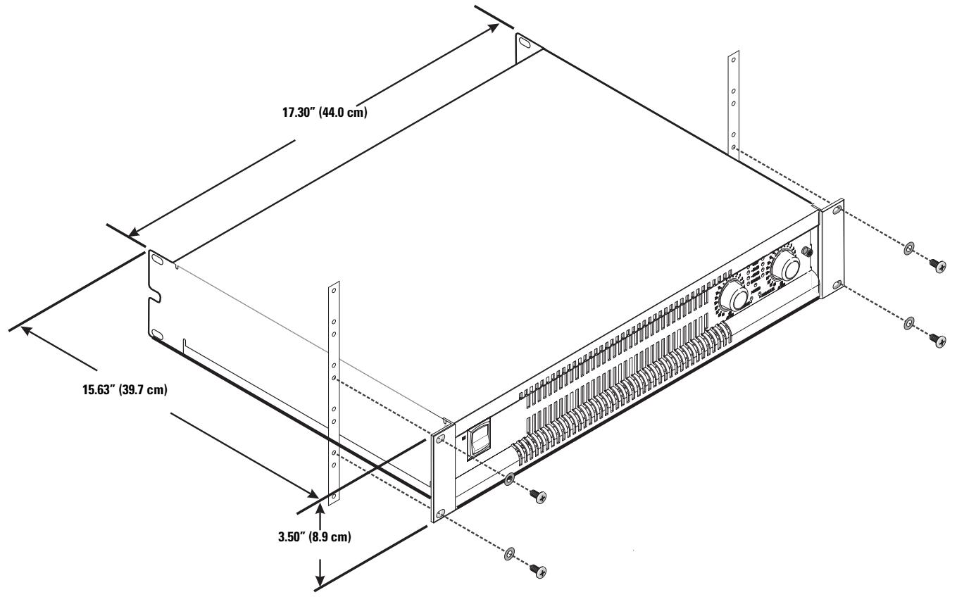
| Dimensions (W x H x D) | 48.3 cm x 8.9 cm (2U) x 39.7 cm |
| Net Weight | 10 kg |
| Power Supply | 120 V or 230 V AC, 50/60 Hz |
| Output Power (1 kHz, 1% THD) | 800 W (8 Ω), 1250 W (4 Ω), 2000 W (2 Ω) per channel; 2600 W (8 Ω), 4000 W (4 Ω) bridge mono |
| Frequency Response | 20 Hz - 20 kHz, ±0.2 dB (8 Ω) |
| Typical Distortion (20 Hz - 20 kHz, 3 dB below clipping) | < 0.02% (8 Ω), < 0.02% (4 Ω), 0.02% (2 Ω) |
| Damping Factor | 500 (8 Ω) |
| Output Circuit Type | Linear Two-Stage Class H |
| Input Sensitivity / Gain | Selectable: 26 dB (3.92 V), 32 dB (1.96 V) or 1.2 V (39.1 dB) |
| Input Impedance | > 10 kΩ, balanced or unbalanced |
| Input Connectors | XLR male/female, 3-pin terminal block, DataPort HD-15 |
| Output Connectors | Neutrik Speakon (4-wire for both channels), binding posts |
| Main Features | Independent per-channel amplitude limiter, selectable 30/50 Hz high-pass filter, bridge/parallel/stereo mode, lockable gain controls, DataPort for remote control |
| Protection | Short circuit, open circuit, thermal, RF, silent on/off, inrush current limitation |
| Cooling | Front-to-back airflow with heat-activated fan |
| Maintenance and Cleaning | Clean with a dry cloth; do not block vents |
| Safety | Do not expose to rain or moisture; unplug before maintenance; refer servicing to qualified personnel |
| Warranty | 3 years (limited, parts and labor) |
| Spare Parts and Repairability | Spare parts available from QSC; repair by authorized centers |
Frequently Asked Questions - PL340 QSC AUDIO
User questions about PL340 QSC AUDIO
0 question about this device. Answer the ones you know or ask your own.
Ask a new question about this device
Download the instructions for your Audio Amplifier in PDF format for free! Find your manual PL340 - QSC AUDIO and take your electronic device back in hand. On this page are published all the documents necessary for the use of your device. PL340 by QSC AUDIO.
USER MANUAL PL340 QSC AUDIO
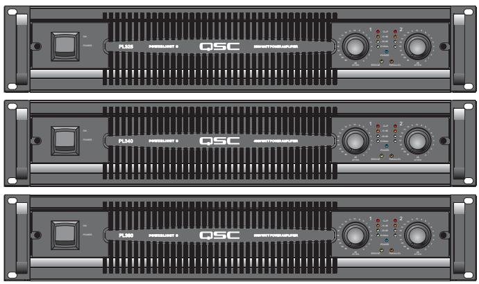
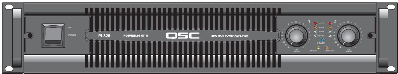
1250 watts per channel at 2 ohms
PL340
2000 watts per channel at 2 ohms
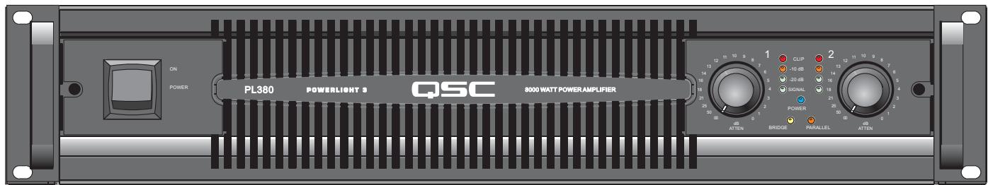
PL380
4000 watts per channel at 2 ohms
Important Safety Precautions & Explanation of Symbols
1- Read these instructions.
2- Keep these instructions.
3-Heed all warnings.
4- Follow all instructions.
5- WARNING: To prevent fire or electric shock, do not expose this equipment to rain or moisture. Do not use this apparatus near water.
6- Clean only with a dry cloth.
7- Do not block any ventilation openings.
8- Do not install near any heat sources such as radiators, heat registers, stoves, or other apparatus (including amplifiers) that produce heat.
9- Do not defeat the safety purpose of the polarized or grounding-type plug. A polarized plug has two blades with one wider than the other. A grounding plug has two blades and a grounding prong. The wide blade or third prong are provided for your safety. If the provided plug does not fit your outlet, consult an electrician for the replacement of the obsolete outlet.
10- Protect the power cord from being walked on or pinched, particularly plugs, convenience receptacles, and the point where they exit from the apparatus.
11- Use only attachments/accessories specified by QSC Audio Products, LLC
12- Use only with hardware, brackets, stands, and components sold with the apparatus or by QSC Audio Products, LLC
13- Unplug the apparatus during lightning storms or when unused for long periods of time.
14- Refer all servicing to qualified service personnel. Servicing is required when the apparatus has been damaged in any way, such as power supply cord or plug is damaged, liquid has been spilled or objects have fallen into the apparatus, the apparatus has been exposed to rain or moisture, does not operate normally, or has been dropped.

The exclamation point within an equilateral triangle is intended to alert the user to the presence of important operating and maintenance (servicing) instructions in this manual.

The lightning flashes printed next to the OUTPUT terminals of the amplifier are intended to alert the user to the risk of hazardous energy. Output connectors that could pose a risk are marked with the lightning flash. Do not touch output terminals while amplifier power is on. Make all connections with amplifier turned off.

The lightning flash with arrowhead symbol within an equilateral triangle is intended to alert the user to the presence of uninsulated "dangerous" voltage within the product's enclosure that may be of sufficient magnitude to constitute a risk of electric shock to humans.

CAUTION: TO REDUCE THE RISK OF ELECTRIC SHOCK, DO NOT REMOVE THE COVER. NO USER-SERVICEABLE PARTS INSIDE. REFER SERVICING TO QUALIFIED PERSONNEL.

WARNING: To prevent fire or electric shock, do not expose this equipment to rain or moisture.
FCC INTERFERENCE STATEMENT FOR PL325 & PL340 MODELS
NOTE: This equipment has been tested and found to comply with the limits for a class B digital device, pursuant to part 15 of the FCC rules. These limits are designed to provide reasonable protection against harmful interference in a residential installation. This equipment generates, uses, and can radiate radio frequency energy and if not installed and used in accordance to the instructions, may cause harmful interference to radio communications. However, there is no guarantee that interference will not occur in a particular installation. If this equipment does cause harmful interference to radio or television reception, which can be determined by switching the equipment off and on, the user is encouraged to try to correct the interference by one or more of the following measures:
- Reorient or relocate the receiving antenna.
- Increase the separation between the equipment and the receiver.
- Connect the equipment into an outlet on a circuit different from that to which the receiver is connected.
- Consult the dealer or an experienced radio or TV technician for help.
FCC INTERFERENCE STATEMENT FOR PL380 MODEL
NOTE: This equipment has been tested and found to comply with the limits for a class A digital device, pursuant to part 15 of the FCC rules. These limits are designed to provide reasonable protection against harmful interference in a residential installation. This equipment generates, uses, and can radiate radio frequency energy and if not installed and used in accordance to the instructions, may cause harmful interference to radio communications. Operation of this equipment in a residential area is likely to cause harmful interference in which case the user will be required to correct at his own expense.
INTRODUCTION
Thank you for choosing PowerLight 3 for your amplification needs. You have joined a worldwide community of professionals who rely on QSC products to perform under all conditions. QSC's vision is to be the most trusted provider of high quality audio products and services to artists and professionals worldwide. We earn that trust through careful design, thorough testing, and obsessive attention to quality and detail, in all phases of manufacturing and service.
The PowerLight 3 Series is based on decades of research and experience in audio power amplification. This series combines the most requested analog input adjustments with easy-to-read LED indicators, making it easy to inspect settings at a glance and match to any system. Because there is no internal digital processing or signal delay, these amplifiers can be freely combined with all types of traditional amplifiers. The QSC DataPort provides access to QSC's full range of digital processors and remote control monitor systems.
The PL325 and PL340 continue the PowerLight legacy started in 1994, combining a powerful, lightweight and efficient switchmode supply with our most advanced Class-H linear output section. Their reference-quality audio performance, high thermal capacity, and touring-grade ruggedness continue to lead the industry.
The PL380 combines the PowerLight supply with a Class-D audio output section, doubling the output power while further reducing losses. The Class-D output section outperforms most competitive linear amplifiers, offering the best full-range audio performance available in this power range. All models have a neutral sonic signature, driving even difficult loads without any distracting behavior or change in tone quality.
In order to control thousands of watts of power smoothly and safely, QSC amplifiers employ many sophisticated protection circuits. These systems provide the highest possible dynamic range without letting the amplifier exceed its safe operating limits. To avoid unwanted triggering of these protection systems, and to protect your valuable speakers, please review these instructions to ensure that you get the full benefit of your amplifier's performance.
PowerLight 3 Power Amplifiers, Watts at Clipping
| Model | 8 ohms | 4 ohms | 2 ohms |
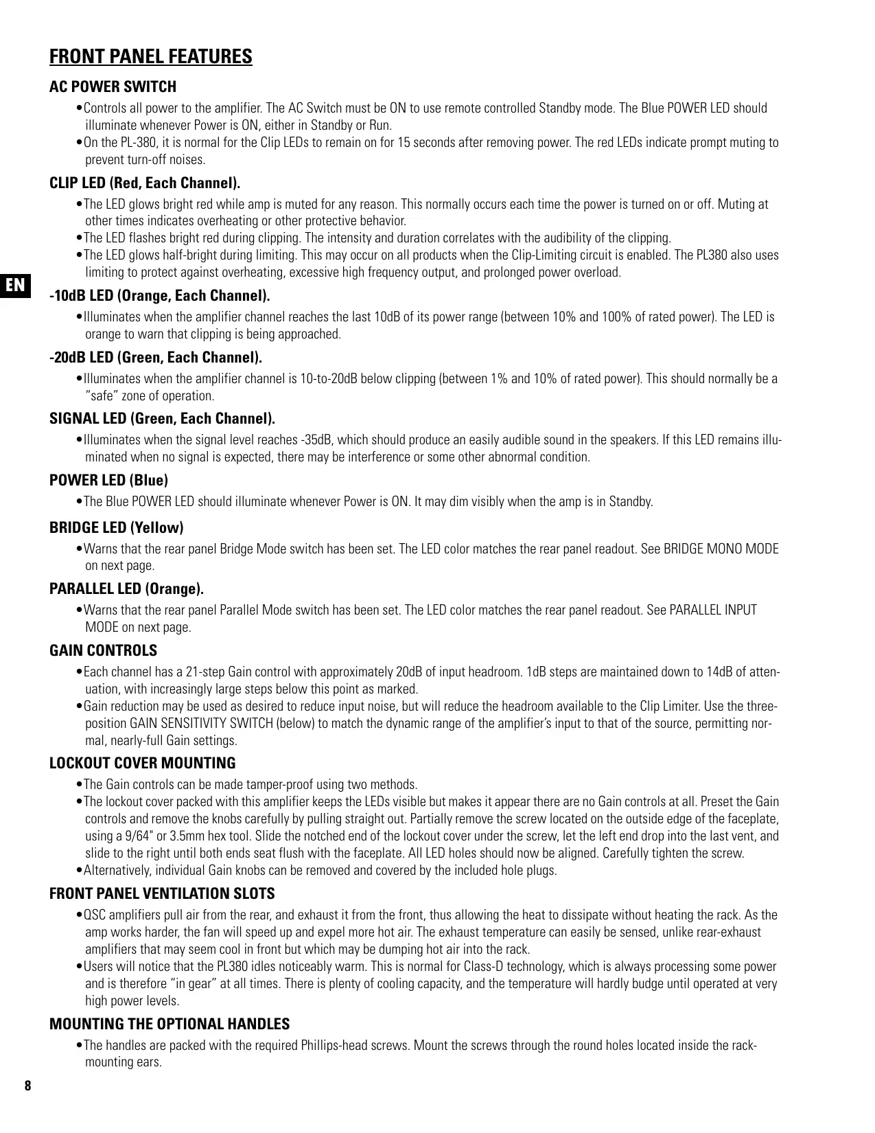
| PL325 | 500 | 850 | 1250 |
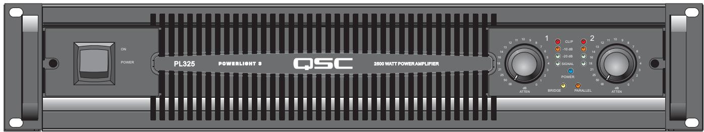
| PL340 | 800 | 1250 | 2000 |
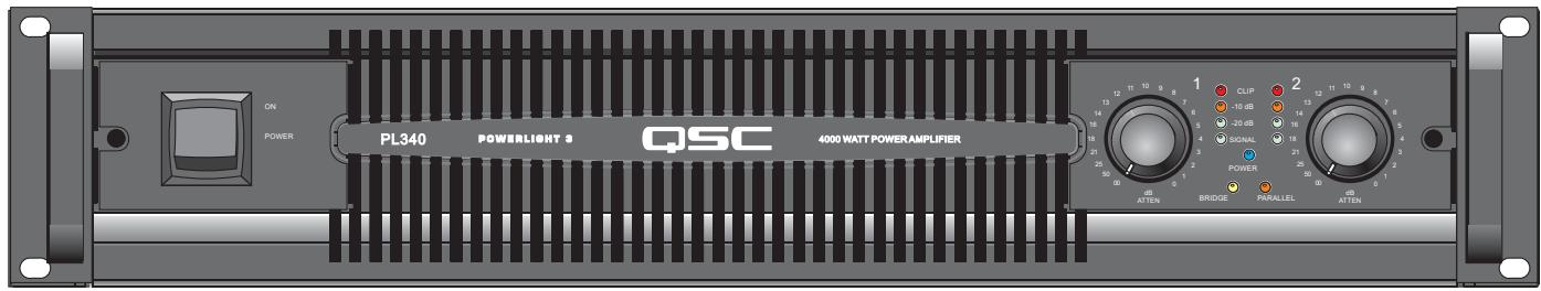
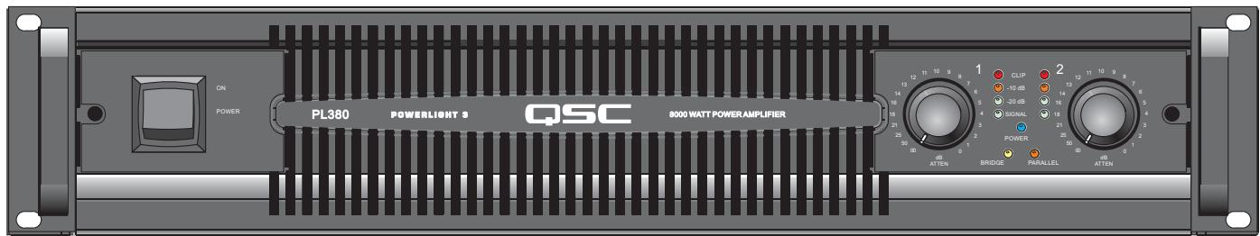
| PL380 | 1500 | 2500 | 4000 |
EIA 1 kHz 1% THD
FEATURES
- PowerLight switchmode power supply for highest efficiency and improved audio performance
- Flow-through air path and solid aluminum heat sinks for maximum cooling
- DataPort supports remote computer control and/or external DSP-4 modules
Detented gain controls with 1 dB steps for precise calibration - Removable knobs with lock-out security plate to prevent unauthorized tampering
- Independent user-defeatable clip limiter and selectable low-frequency filter for each channel
- Three selectable input gains (26 dB, 32 dB, or 1.2V)
- Front and rear panel LEDs indicate status of switch settings at a glance
- Parallel XLR male, XLR female, 3-pin header, and DataPort connectors for simple loop-through connectivity
- Neutrik Speakon® and "touch proof" binding post outputs
- Neutrik PowerCon® power cable remains secure on the road
- 3 year warranty, plus optional 3 year extended service contract
PL325 and PL340
- Linear class-H output circuit doubles the standard class-B efficiency, reducing cooling and AC current requirements
PL380
Class-D output circuit re-doubles the output power with even lower losses and minimal increase in average AC power, dramatically reducing AC power distribution demands compared to older, high-power amplifiers
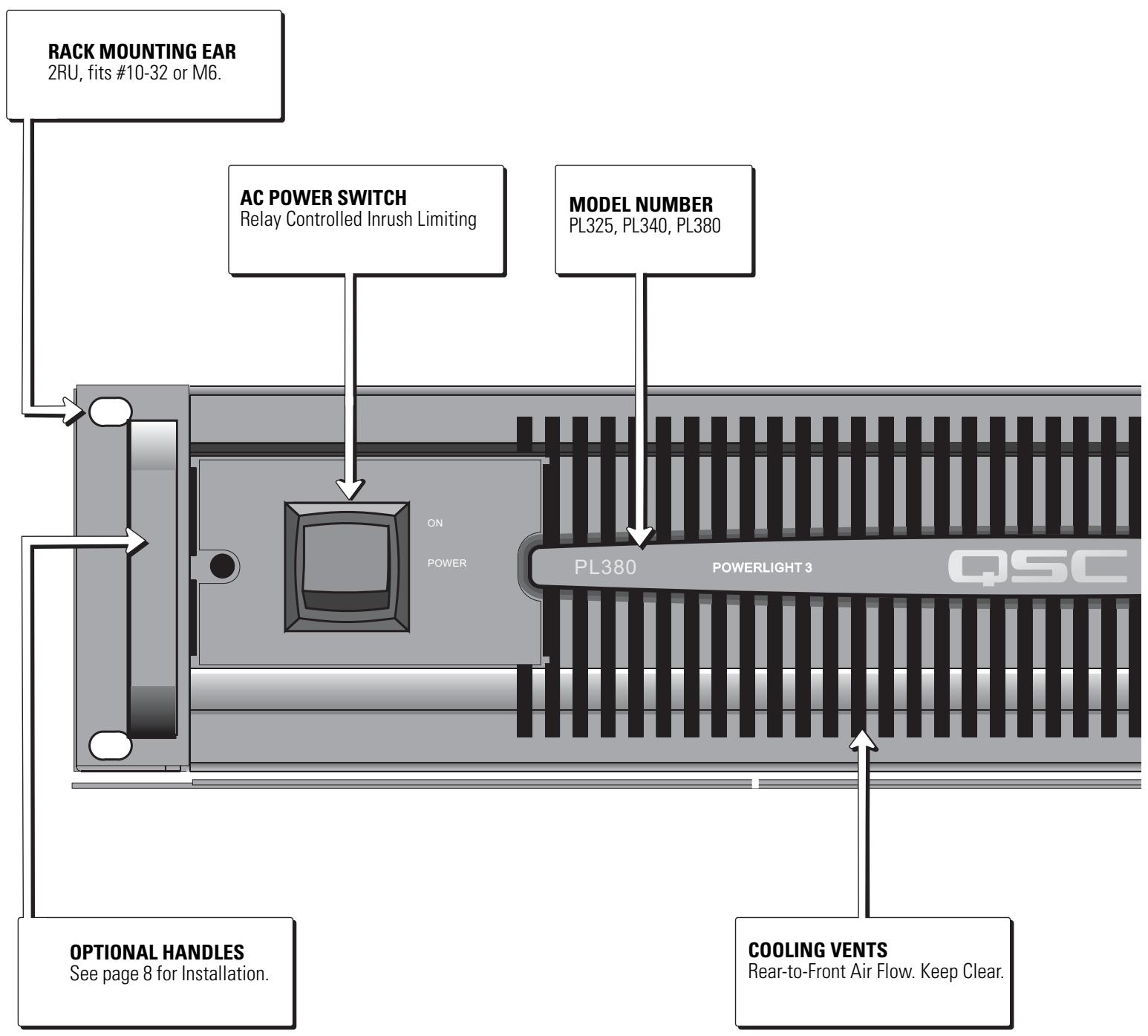

FRONT PANEL FEATURES
AC POWER SWITCH
- Controls all power to the amplifier. The AC Switch must be ON to use remote controlled Standby mode. The Blue POWER LED should illuminate whenever Power is ON, either in Standby or Run.
- On the PL-380, it is normal for the Clip LEDs to remain on for 15 seconds after removing power. The red LEDs indicate prompt muting to prevent turn-off noises.
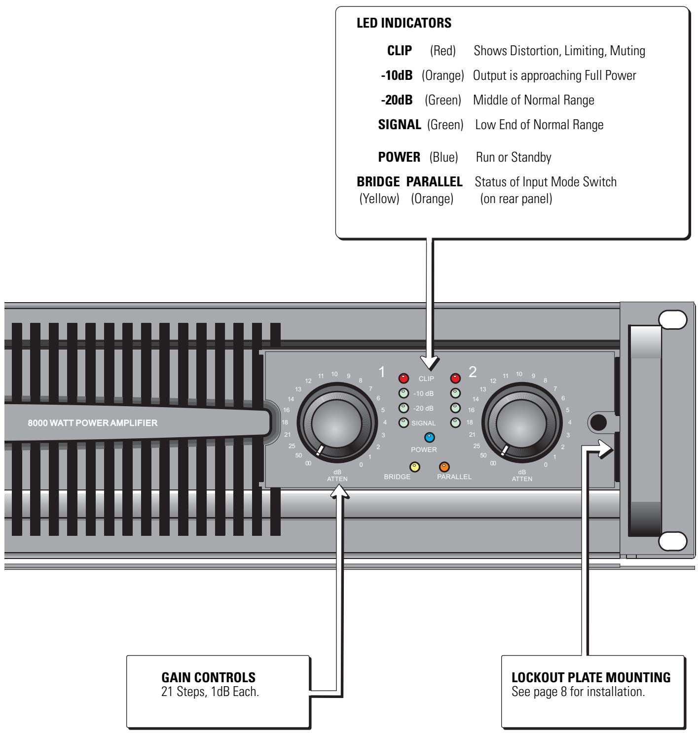
CLIP LED (Red, Each Channel).
- The LED glows bright red while amp is muted for any reason. This normally occurs each time the power is turned on or off. Muting at other times indicates overheating or other protective behavior.
The LED flashes bright red during clipping. The intensity and duration correlates with the audibility of the clipping. - The LED glows half-bright during limiting. This may occur on all products when the Clip-Limiting circuit is enabled. The PL380 also uses limiting to protect against overheating, excessive high frequency output, and prolonged power overload.
-10dB LED (Orange, Each Channel).
- Illuminates when the amplifier channel reaches the last 10dB of its power range (between 10% and 100% of rated power). The LED is orange to warn that clipping is being approached.
-20dB LED (Green, Each Channel).
- Illuminates when the amplifier channel is 10-to-20dB below clipping (between 1% and 10% of rated power). This should normally be a "safe" zone of operation.
SIGNAL LED (Green, Each Channel).
- Illuminates when the signal level reaches -35dB, which should produce an easily audible sound in the speakers. If this LED remains illuminated when no signal is expected, there may be interference or some other abnormal condition.
POWER LED (Blue)
- The Blue POWER LED should illuminate whenever Power is ON. It may dim visibly when the amp is in Standby.
BRIDGE LED (Yellow)
- Warns that the rear panel Bridge Mode switch has been set. The LED color matches the rear panel readout. See BRIDGE MONO MODE on next page.
PARALLEL LED (Orange).
- Warns that the rear panel Parallel Mode switch has been set. The LED color matches the rear panel readout. See PARALLEL INPUT MODE on next page.
GAIN CONTROLS
Each channel has a 21-step Gain control with approximately 20dB of input headroom. 1dB steps are maintained down to 14dB of attenuation, with increasingly large steps below this point as marked.
- Gain reduction may be used as desired to reduce input noise, but will reduce the headroom available to the Clip Limiter. Use the three-position GAIN SENSITIVITY SWITCH (below) to match the dynamic range of the amplifier's input to that of the source, permitting normal, nearly-full Gain settings.
LOCKOUT COVER MOUNTING
- The Gain controls can be made tamper-proof using two methods.
- The lockout cover packed with this amplifier keeps the LEDs visible but makes it appear there are no Gain controls at all. Preset the Gain controls and remove the knobs carefully by pulling straight out. Partially remove the screw located on the outside edge of the faceplate, using a 9 / 64" or 3.5mm hex tool. Slide the notched end of the lockout cover under the screw, let the left end drop into the last vent, and slide to the right until both ends seat flush with the faceplate. All LED holes should now be aligned. Carefully tighten the screw.
- Alternatively, individual Gain knobs can be removed and covered by the included hole plugs.
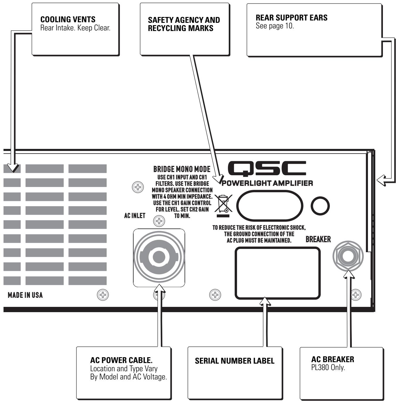
FRONT PANEL VENTILATION SLOTS
- QSC amplifiers pull air from the rear, and exhaust it from the front, thus allowing the heat to dissipate without heating the rack. As the amp works harder, the fan will speed up and expel more hot air. The exhaust temperature can easily be sensed, unlike rear-exhaust amplifiers that may seem cool in front but which may be dumping hot air into the rack.
- Users will notice that the PL380 idles noticeably warm. This is normal for Class-D technology, which is always processing some power and is therefore "in gear" at all times. There is plenty of cooling capacity, and the temperature will hardly budge until operated at very high power levels.
MOUNTING THE OPTIONAL HANDLES
- The handles are packed with the required Phillips-head screws. Mount the screws through the round holes located inside the rackmounting ears.
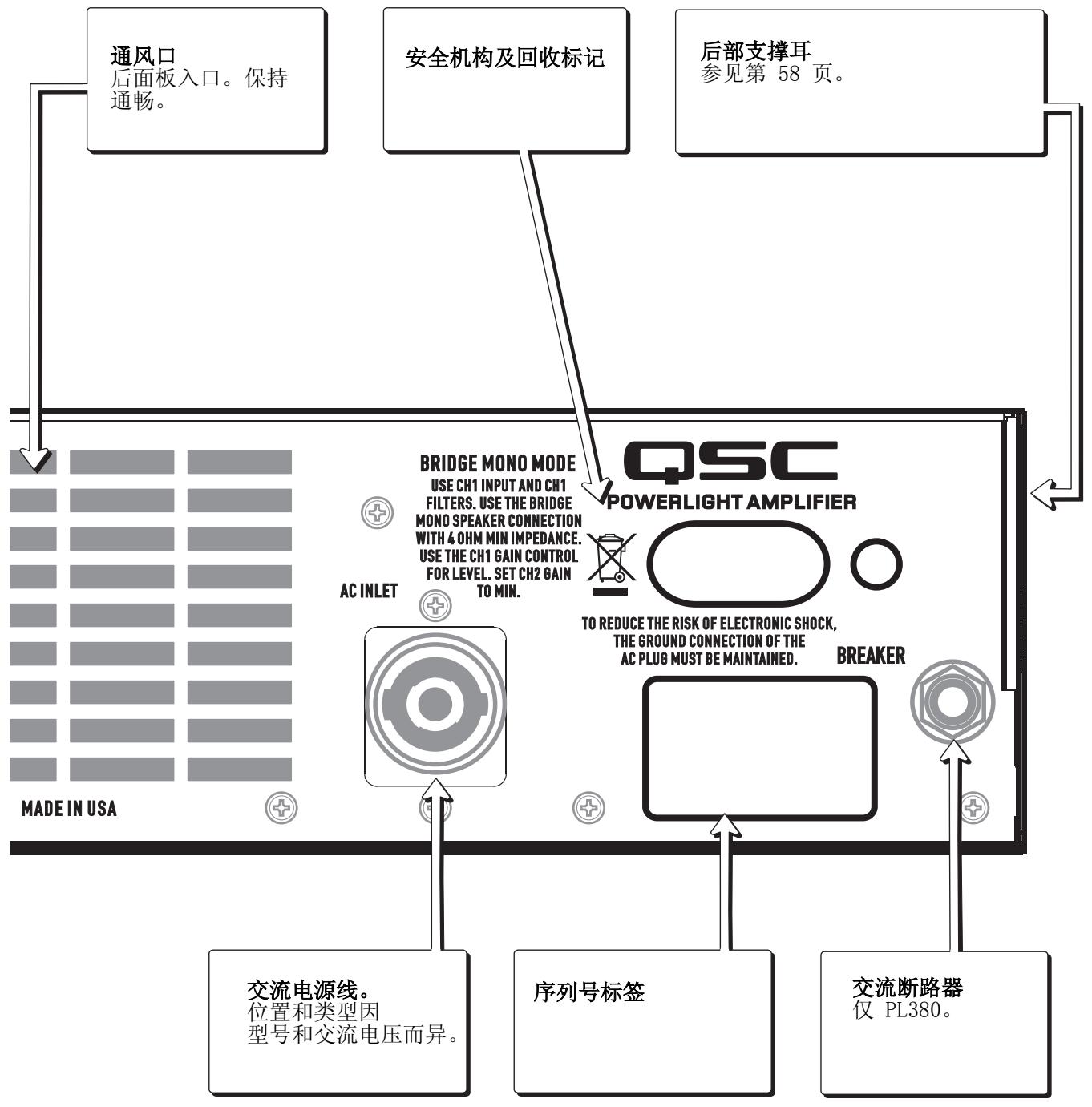
REAR PANEL FEATURES
INPUT CONNECTIONS
- Precision balanced inputs offer superior hum rejection, and accept >21dBu input levels on all Sensitivity settings (see Specs).
- Female and Male XLR, Pluggable Terminal Blocks, and DataPort Input signals are all wired in parallel for each channel.
- Paralleled DataPort routing is used for the first time on the PL3 series. Therefore, DataPort-connected signals can be patched to other amplifiers. Do not use unbalanced connectors as this will unbalance and possibly affect the level of all signals connected to that channel.
- Because the DataPort signals on the PL3 Series are connected like any other input, the Sensitivity switch will affect gain for these inputs as well. QSControl devices will read the setting of the Sensitivity Switch to allow for this.
REMOTE MONITORING - DATAPORT
- All DataPort connected accessories are supported. The usual signals representing output voltage, output current, clipping, temperature, supply voltage and switch status are provided, plus remote control Standby. The current version of QSControl will read a unique ID code and know what PL3 models are connected without operator intervention.
CLIP LIMITING, ON-OFF SWITCH (Ch1, Ch 2)
- Each channel provides a Clip-Limit switch; with an adjacent yellow LED for "ON". PL3 Clip Limiting is designed to reduce the audibility of clipping without changing the program dynamics in any other way. It replaces harsh clipping with very rapid limiting, "reducing" rather than "eliminating" clipping. This is not a substitute for long-term power limiting, as average program levels can still be driven very high.
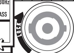
HIGH PASS FILTER, 3-POSITION SWITCH (Ch1, Ch2)
- For simple systems, second-order (12dB/octave) filters can be engaged at 30Hz (yellow LED) or 50Hz (orange LED). These filters can prevent speakers from sub-audio overload, but can have an audible effect on percussive material. Their effect should be auditioned carefully. When bypassed (no LED), the low frequency response extends to about 3Hz . In this wide-band mode, very large sub-audio transients may trigger brief protective muting.
INPUT MODE SWITCH, 3-POSITION: BRIDGE, STEREO, PARALLEL
- BRIDGE MONO MODE (Yellow LED): Sends Ch1 signals out-of-phase to Ch2, producing twice the normal voltage swing between the two "red" speaker terminals (Ch1 "red" is defined as positive). Only Ch1 controls and input are effective. USE EXTREME CAUTION when connecting speakers. Depending on the model, hundreds of volts and thousands of watts are available. NOTE: it is normal for the Br Mono indicator LED to change slowly.
- STEREO MODE (Green LED). Each channel operates independently, as usual.
- PARALLEL INPUT MODE (Orange LED). The inputs of both channels are directly connected together, but all controls and speaker connections work as usual. Never connect the red output terminals directly together.
INPUT SENSITIVITY SWITCH, 3-POSITION: 26dB, 32dB, 1.2V
- The 26dB (Orange) and 32dB (Green) settings provide the same voltage gain for all models. When using these settings, all models will sound equally loud, but the more powerful amp will have more headroom.
- The 1.2V setting provides the same input sensitivity for all models. Larger amps will sound proportionally louder, with the same amount of headroom.
- The resulting input sensitivities and gains for each model are shown in the Specs.
SPEAKER CONNECTIONS - SPEAKONS
- Ch1 provides "4-wire" access to both channels using the standard convention: Ch1 uses 1+, 1-, and Ch 2 uses 2+ and 2-
- Ch 2 provides "2 wire" access to Ch 2 only, using 1+ , 1-.
SPEAKER CONNECTIONS - BINDING POSTS
- WARNING: use safe wiring practice as peak output voltages can be hazardous.
AC POWER CABLE AND AC VOLTAGES.
- PL3 Series amplifiers are configured for specific AC voltages. The products operate safely over the normal range of AC line variation but rated performance applies only at rated voltage.
- Where regulations permit, products feature locking detachable cordsets, and are shipped with AC plugs suitable for the intended AC voltage (see Specs).
Rack Mounting and Dimensions
Use four screws and washers to mount the amplifier to the equipment rack rails. To use the amplifier outside a rack, attach the self-adhesive rubber feet to the bottom.
For portable, mobile, or other applications where the rack assembly may be moved, we strongly recommend supporting the rear of the amplifier. A rear rack ear kit is available from QSC's Technical Services Group.
Optional rack handles provide finger grips at each end, making lifting and setting into the rack more comfortable.
AC Mains Current Draw
This table provides typical current draw for each model as a function of load and output power level. Units of measurement are amperes rms.
NOTE! Current draw shown is for 120 VAC line. For 230 VAC models, multiply values shown by 0.5.
- 1/8 power (pink noise) represents typical program with occasional clipping. Use this rating for most applications.
- 1/3 power (pink noise) represents severe program with heavy clipping.
Full power (sine) is continuous sine wave driven at 1% clipping.
| Model | Load | Idle Current (Amperes) | 1/8 Power Pink Noise | BTU | 1/3 Power Pink Noise | BTU | Full Power Sine Wave | BTU |
| PL325 | 8 ohms x 2 | 1.0 | 5.2 A | 792 | 8.6 A | 893 | 17.0 A | 1204 |
| 4 ohms x 2 | 8.5 A | 1387 | 14.3 A | 1981 | 28.3 A | 2481 | ||
| 2 ohms x 2 | 12.6 A | 2178 | 22.0 A | 3339 | 45.3 A | 4942 | ||
| PL340 | 8 ohms x 2 | 1.0 | 7.5 A | 1150 | 13.3 A | 1682 | 25.9 A | 2082 |
| 4 ohms x 2 | 11.8 A | 2114 | 21.1 A | 2864 | 43.5* A | 4253* | ||
| 2 ohms x 2 | 19.1 A | 3495 | 31.6* A | 5306* | 68.6* A | 8601* | ||
| PL380 | 8 ohms x 2 | 2.8 | 8.7 A | 918 | 16.0 A | 1101 | 38.3 A | 1853 |
| 4 ohms x 2 | 13.1 A | 1355 | 26.2 A | 1674 | 70* A | 3000* | ||
| 2 ohms x 2 | 19.3 A | 1768 | 41.6* A | 3278* | 100* A | 6000* |
| Specifications | PL325 | PL340 | PL380 | |
| MAXIMUM OUTPUT POWER 1kHz, 1% clipping | ||||
| 8 ohms, both channels driven | 500 | 800 | 1500 | |
| 4 ohms, both channels driven | 850 | 1250 | 2500 | |
| 2 ohms, both channels driven | 1250 | 2000 | 4000* | |
| 8 ohms, bridge mono | 1700 | 2600 | 5000 | |
| 4 ohms, bridge mono | 2500 | 4000 | 8000* | |
| (*Burst mode testing required due to AC service current limitations) | ||||
| TYPICAL DISTORTION 20-3kHz, 3dB below clip, or 20-5kHz, 10dB below clip, or 20-20kHz, 20dB below clip | ||||
| 8 ohms | 0.002-0.01% | 0.002-0.01% | 0.01-0.03% | |
| 4 ohms | 0.005-0.01% | 0.005-0.01% | 0.03-0.06% | |
| 2 ohms | 0.02% | 0.02% | 0.10% | |
| MAXIMUM DISTORTION 4-8 ohms | 0.05% | 0.05% | 0.20% | |
| 20-20kHz, 1dB below rated power | ||||
| FREQUENCY RESPONSE | 8 ohms | 20-20kHz, +/-0.2dB, all models. | ||
| NOISE FLOOR | 20-20kHz, 32dB Gain | -106dB | -105dB | -104dB |
| DYNAMIC HEADROOM | 4 ohms | 2dB all models | ||
| DAMPING FACTOR | 8 ohms | 500 | 500 | 200 |
| OUTPUT CIRCUIT TYPE | Class-H (2 tier) | Class-H (2 tier) | Class-D | |
| INPUT SENSITIVITY | (26dB Setting) | 3.28V | 3.92V | 5.27V |
| (32dB Setting) | 1.60V | 1.96V | 2.67V | |
| INPUT GAIN | (1.2V Setting) | 34.5dB | 36.4dB | 39.1dB |
| INPUT IMPEDANCE | >10k ohms, balanced or unbalanced, all models. | |||
| MAXIMUM INPUT LEVEL | (1.2V Setting) | 11V (+23dB) | 11V(+23dB) | 10V (+22dB) |
| (32dB Setting) | 14.6V (+25.5dB) | 18V (+27.4dB) | 22V (+29dB) | |
| (26dB Setting) | 25V (+30dB) | 25V (+30dB) | 25V (+30dB) | |
| CONTROLS and LEDs, FRONT PANEL | Each channel: | AC Power Switch, Power (Blue), Br Mono (Yellow), Par (Orange) | ||
| Gain Control, 21 detents, 1dB steps. | ||||
| Signal -35dB, -20dB (Green), -10dB (Orange), Clip (Red). | ||||
| CONTROLS and LEDs, REAR PANEL | Common: | Input Mode: Parallel (Orange), Stereo (Green), Br Mono (Yellow) | ||
| Sensitivity: 26dB (Orange), 32dB (Green), 1.2V (Yellow). | ||||
| Each channel: | LF Filter: Off, 30Hz (Yellow), 50Hz (Orange) | |||
| Clip Limit: Off, On (Yellow) | ||||
| INPUT CONNECTORS | Common: | HD-15 DataPort (inputs wired in parallel with XLR) | ||
| Each channel: | Male XLR, Female XLR, 3-pin terminal block connector. | |||
| OUTPUT CONNECTORS | Each channel: | 5-way Binding Posts, Output Red, Common Black Neutrik Speakon, (Ch 1, 4-wires, accesses both channels). | ||
| AMPLIFIER AND LOAD PROTECTION | Short circuit, open circuit, thermal, RF protection. On/off muting, DC fault shutdown, active inrush limiting. | |||
| AC POWER, CORDSET | 120V 50/60Hz | 8.5A, NEMA-15 | 12A, NEMA-15 | 18A, NEMA L5-30P |
| 230V 50Hz | 7.5A, Euro 16A | 7A, Euro 16A | 11A, Euro 16A | |
| DIMENSIONS | All models | 2RU, depth 15.63" (39.7cm), mounting rails to rear support ears | ||
| WEIGHT | Net | 22lbs (10kg) | 22lbs (10kg) | 24lbs (11kg) |
| Shipping | 31.5lbs (14.3kg) | 31.5lbs (14.3kg) | 33.5lbs (15.2kg) | |
Warranty (USA only: other countries, see your dealer or distributor)
Disclaimer
QSC Audio Products, LLC is not liable for any damage to amplifiers or any other equipment that is caused by negligence or improper installation and/or use of this loudspeaker product.
QSC Audio Products 3 Year Limited Warranty
QSC Audio Products, LLC ("QSC") guarantees its products to be free from defective material and / or workmanship for a period of three (3) years from date of sale, and will replace defective parts and repair malfunctioning products under this warranty when the defect occurs under normal installation and use - provided the unit is returned to our factory or one of our authorized service stations via prepaid transportation with a copy of proof of purchase (i.e., sales receipt). This warranty provides that the examination of the return product must indicate, in our judgment, a manufacturing defect. This warranty does not extend to any product which has been subjected to misuse, neglect, accident, improper installation, or where the date code has been removed or defaced. QSC shall not be liable for incidental and/or consequential damages. This warranty gives you specific legal rights. This limited warranty is freely transferable during the term of the warranty period.
Customer may have additional rights, which vary from state to state.
In the event that this product was manufactured for export and sale outside of the United States or its territories, then this limited warranty shall not apply. Removal of the serial number on this product, or purchase of this product from an unauthorized dealer, will void this limited warranty.
Periodically, this warranty is updated. To obtain the most recent version of QSC's warranty statement, please visit www.qscaudio.com.
Contact us at 800-854-4079 or visit our website at www.qscaudio.com.
How to Contact QSC Audio Products
Mailing address:
QSC Audio Products, LLC
1675 MacArthur Boulevard
Costa Mesa, CA 92626-1468 USA
Telephone Numbers:
Main Number (714) 754-6175
Sales & Marketing (714) 957-7100 or toll free (USA only) (800) 854-4079
Customer Service (714) 957-7150 or toll free (USA only) (800) 772-2834
Facsimile Numbers:
Sales & Marketing FAX (714) 754-6174
Customer Service FAX (714) 754-6173
World Wide Web:
www.qscaudio.com
E-mail:
info@qscaudio.com
service@qscaudio.com
Copyright 2007, QSC Audio Products, LLC
QSC Audio Products, LLC
1675 MacArthur Boulevard
service@qscaudio.com
Copyright 2007, QSC Audio Products, LLC
SELECTIONGAIN SENSITIVITYA3POSITIONS:26dB,32dB,1.2V
CABLE D'ALIMENTATION ET TENSION C.A.
QSC Audio Products, LLC
1675 MacArthur Boulevard
service@qscaudio.com
Copyright 2007, QSC Audio Products, LLC
QSC Audio Products, LLC
1675 MacArthur Boulevard
Costa Mesa, CA 92626-1468 USA
Telefonnummern:
service@qscaudio.com
PL325 1250W/通道,2欧姆
PL340 2000W/通道,2欧姆
PL380 4000W/通道,2欧姆

重要的安全注意事项和符号说明
© 版权 2007, QSC Audio Products, LLC
QSC是QSC Audio Products,LLC的注册商标
m = 311 ;
50Hz
( x - 2x) t - xy^2 = ( x - 2x) f^ t
30Hz
CH1
OF
HIGH
PASS

1
-
一
BRIDGE STEREO PARALLI

GAIN SENSITIVITY
O O O
26dB 32dB 1.2V

1
1
1
1
1
112
1
1
be
P0
1
NE
CUL2
CLIP LIM
055
)
一
-
CH2
CH2
RRID:
PINOUT
POS NEG POS NEG POS NEG
OUTP
UTS
S-

1
EG
A
6


CH1


QSC DATAPORT
支持QSC DataPort产品。
输入
灵敏度
开关
26dB(橙色)
32dB(绿色)
1.2V(黄色)
参见规格部分
了解相应数
值。

接线柱
红色,扬声器,高压
黑色,通用。
NEUTRIK SPEAKON 接头
通道1:4线连接到通道1和通道2
通道2:2线连接,仅连接到通道2
前面板功能
交流电源开关
QSC Audio Products, LLC
1675 MacArthur Boulevard
Costa Mesa, CA 92626-1468 USA
电话:
主要号码 (714) 754-6175
service@qscaudio.com
- Important Safety Precautions & Explanation of Symbols
- FCC INTERFERENCE STATEMENT FOR PL325 & PL340 MODELS
- FCC INTERFERENCE STATEMENT FOR PL380 MODEL
- INTRODUCTION
- FEATURES
- PL325 and PL340
- PL380
- FRONT PANEL FEATURES
- AC POWER SWITCH
- CLIP LED (Red, Each Channel).
- -10dB LED (Orange, Each Channel).
- -20dB LED (Green, Each Channel).
- SIGNAL LED (Green, Each Channel).
- POWER LED (Blue)
- BRIDGE LED (Yellow)
- PARALLEL LED (Orange).
- GAIN CONTROLS
- LOCKOUT COVER MOUNTING
- FRONT PANEL VENTILATION SLOTS
- MOUNTING THE OPTIONAL HANDLES
- REAR PANEL FEATURES
- INPUT CONNECTIONS
- REMOTE MONITORING - DATAPORT
- CLIP LIMITING, ON-OFF SWITCH (Ch1, Ch 2)
- HIGH PASS FILTER, 3-POSITION SWITCH (Ch1, Ch2)
- INPUT MODE SWITCH, 3-POSITION: BRIDGE, STEREO, PARALLEL
- INPUT SENSITIVITY SWITCH, 3-POSITION: 26dB, 32dB, 1.2V
- SPEAKER CONNECTIONS - SPEAKONS
- SPEAKER CONNECTIONS - BINDING POSTS
- AC POWER CABLE AND AC VOLTAGES.
- Rack Mounting and Dimensions
- AC Mains Current Draw
- NOTE! Current draw shown is for 120 VAC line. For 230 VAC models, multiply values shown by 0.5.
- Warranty (USA only: other countries, see your dealer or distributor)
- Disclaimer
- QSC Audio Products 3 Year Limited Warranty
- How to Contact QSC Audio Products
- Mailing address:
- Telephone Numbers:
- Facsimile Numbers:
- World Wide Web:
- E-mail:
- SELECTIONGAIN SENSITIVITYA3POSITIONS:26dB,32dB,1.2V
- CABLE D'ALIMENTATION ET TENSION C.A.
- Telefonnummern:
- 重要的安全注意事项和符号说明
- QSC DATAPORT
- 输入
- 灵敏度
- 开关
- 接线柱
- NEUTRIK SPEAKON 接头
- 前面板功能
- 交流电源开关
- 电话:
Brand : QSC AUDIO
Model : PL340
Category : Audio Amplifier