
CX 4 - Audio Amplifier QSC AUDIO - Free user manual and instructions
Find the device manual for free CX 4 QSC AUDIO in PDF.
| Brand | QSC AUDIO |
| Model | CX 4 |
| Product type | Audio power amplifier |
| Number of channels | 4 (standard estimate) |
| Maximum output voltage | Up to 160 V RMS in bridged mono mode (200 V on isolated outputs for T models) |
| Power supply | 100-240 V AC, 50/60 Hz |
| Dimensions (W x H x D) | 483 x 89 x 400 mm (2U rack format, estimate) |
| Weight | Approximately 9 kg (estimate) |
| Main functions | Audio amplification, stereo/parallel/bridged modes, short circuit and overheating protection |
| Audio inputs | XLR and TRS (6.35 mm jack) (common estimate) |
| Speaker outputs | Screw terminals (estimate) |
| Cooling | Built-in fan (estimate) |
| Safety | Compliant with safety standards; do not expose to rain or moisture; do not open the cover |
| Maintenance and cleaning | Disconnect before cleaning; use a dry cloth; do not use solvents |
| Repairability | Refer all repairs to qualified personnel; no user-serviceable parts |
| General information | Professional amplifier for fixed installation or touring; T models available for high impedance systems (140V/200V) |
Frequently Asked Questions - CX 4 QSC AUDIO
User questions about CX 4 QSC AUDIO
0 question about this device. Answer the ones you know or ask your own.
Ask a new question about this device
Download the instructions for your Audio Amplifier in PDF format for free! Find your manual CX 4 - QSC AUDIO and take your electronic device back in hand. On this page are published all the documents necessary for the use of your device. CX 4 by QSC AUDIO.
USER MANUAL CX 4 QSC AUDIO
Speaker Damage 3
Speaker Output Shock Hazard 3
Rack Mounting Precautions 3
II. Overall Description 4
III. Inputs 6
Input Sensitivities 6
IV. Outputs 6
V. Controls & Displays 8
VI. Operation 8
AC Power 8
Operation 8
Troubleshooting 9
Open Input ArchitectureTM Level I 10
Parallel, Stereo, or Bridged Operation 11
Maximum Long-Term Output Power 13
AC Current Consumption 13
Heat Emissions 14
Protection Circuits 15
VII. Specifications 16
PART 2-CX APPLICATION GUIDE 19
VIII. Distributed Lines 19
IX. Designing the Distributed Sound System 20
Loudspeaker Coverage and Placement 20
Determining Power Levels 22
Selecting the Amplifier 23
Using Components with Different Voltages 24
X. How Many Speakers? 25
XI. Other Design Considerations 26
Speaker Transformer Saturation 26
Connecting Both a Distributed Line and a Direct Loudspeaker on One Channel 26
Wire Loss 27
AC Current Consumption 29
Heat Emissions 29
XII. Address & Telephone Information 30
EXPLANATION OF GRAPHICAL SYMBOLS
The lightning flash with arrowhead symbol, within an equilateral triangle, is intended to alert the user to the presence of uninsulated "dangerous voltage" within the product's enclosure that may be of sufficient magnitude to constitute a risk of electric shock to humans.

The exclamation point within an equi-lateral triangle is intended to alert the users to the presence of important operating and maintenance (servicing) instructions in the literature accompanying the product.
EXPLICATION DES SYMBOLES GRAPHIQUES

DECLARATION OF CONFORMITY for all CX and CXT models
We declare as our sole responsibility that this product is in compliance with the EMC Directive 89/336/EEC and conforms to the requirements of the Harmonized Product Standards EN 55013 (Product Emissions), and EN 55020 (Product Immunity).

CAUTION
RISK OF ELECTRIC SHOCK DONOTOPEN

CAUTION: To reduce the risk of electric shock, do not remove the cover. No user-serviceable parts inside. Refer servicing to qualified service personnel.
WARNING: To prevent fire or electric shock, do not expose this equipment to rain or moisture.

AVIS
RISQUEDEGHOCÉLECTRIQUE NE PAS OUVRIR

Electrical energy can perform many useful functions. This unit has been engineered and manufactured to assure your personal safety. Improper use can result in potential electrical shock or fire hazards. In order not to defeat the safeguards, observe the following instructions for its installation, use and servicing.
PRECAUTIONS
The CX Series amplifiers are among the most powerful professional amplifiers available and are capable of producing much more power than many loudspeakers can handle. It is the user's responsibility to use suitable speakers with the amplifier and to use them in a sensible way that will not cause damage.
QSC will not be responsible for blown speakers. Consult the speaker manufacturer for power-handling recommendations.
Even if you reduce the gain using the amplifier's rear panel attenuator controls, it is still possible to reach full output power if the input signal level is high enough.
A single high-power crescendo can blow high-frequency speaker drivers almost instantaneously, while low-frequency drivers can usually withstand very high, continuous power levels for a few seconds before they too die. Reduce power immediately if you hear any speaker "bottoming out"-harsh pops or cracking distortion that indicate that the speaker voice coil or diaphragm is striking the magnet assembly.
QSC recommends that you use amplifiers of this power range for more headroom (cleaner sound) rather than for increased volume.
SPEAKER OUTPUT SHOCK HAZARD
A CX amplifier is capable of producing hazardous output voltages. To avoid electrical shock, make sure the cover is in place over the output terminals, and do not touch any exposed speaker wiring while the amplifier is operating.
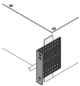
RACK MOUNTING PRECAUTIONS
To minimize twisting stress on the front mounting ears, the amplifier's internally mounted output transformers are located close to the front panel. Nevertheless, when rack mounting any CX amplifier, make sure it is well
supported at all four corners to avoid damage to either the amplifier mounting ears or the mounting rails.
Contact the QSC Technical Services Department to order rear support brackets.

Optional rear rack mounting ears.
LIFTING PRECAUTIONS
In order to safely move or install the amplifier, it is recommended that two persons share the weight when lifting and positioning the unit.
II. Overall Description
The CX Series from QSC comprises six high-efficiency professional power amplifier models, each with two independent channels. The table below lists the range's audio power ratings.
| MODEL | 8Ω1 | 4Ω1 | 2Ω2 | 25 volts3 | 70 volts1 | 100 volts1 |
| CX4 | 150 watts | 225 watts | 350 watts | |||
| CX4T | 150 watts | 225 watts | 350 watts | 150 watts4 | 175 watts4 | 175 watts4 |
| CX6 | 200 watts | 300 watts | 450 watts | |||
| CX6T | 200 watts | 300 watts | 450 watts | 200 watts3 | 250 watts3 | 250 watts3 |
| CX12 | 425 watts | 600 watts | 900 watts | |||
| CX12T | 425 watts | 600 watts | 900 watts | 400 watts3 | 500 watts3 | 500 watts3 |
| 1: FTC watts per channel, 20 Hz-20 kHz, 0.1% THD | ||||||
| 2: EIA watts per channel, 1 kHz, 1% THD | ||||||
| 3: Watts per channel, 45 Hz-15 kHz, 0.25% THD | ||||||
| 4: Watts per channel, 50 Hz-15 kHz, 0.25% THD | ||||||
Each channel has its own power transformer secondary. The CX4, CX4T, CX6 and CX6T utilize complementary Class AB linear output circuitry. For improved efficiency, the CX12 and CX12T utilize Class H step linear complementary output circuitry and have bipolar multi-rail power supplies. The power transformers, as are the output transformers, are mounted in the front of the amplifier chassis, as close to the front mounting rails as
possible; this keeps the unit's center of gravity forward to minimize the twisting force on the front mounting ears. Still, the amplifier should be supported at all four corners, especially if it is in a portable rack.
The CX4 and CX4T are two rack spaces high; the CX6, CX6T, CX12, and CX12T are three rack spaces high. The adjacent table lists the amplifiers' weights by model.
The amplifiers require a rack depth of 18 inches (45.7 cm) to clear the rear support ears. Allow some additional clearance for input and output connectors at the rear panel, which is 16.9 inches (42.9 cm) behind the plane of the front mounting rails. The built-in cooling fan draws air in at the rear of the chassis and exhausts it through vents in the front panel. The flow-through cooling scheme allows you to rack-mount the amplifiers one atop the other, with no clearance necessary in between. This mounting technique also helps support the weight of the upper amplifiers.
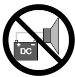
The CX Series derives much of its design from our award-winning MXa Series amplifiers. They are engineered for stability and exceptional reliability, with protection for open or short circuits and mismatched loads. To protect your loudspeakers, the outputs mute during turn-on and turn-off, and also in the event of a DC fault. The CX4 and CX4T are AC coupled and cannot pass DC to the load. Therefore, the DC fault mating is not required. All protection circuitry automatically resets to normal when conditions assure safe operation.
Every CX amplifier features thermal management and protection in the form of a two-speed fan and extruded aluminum heat sinks with direct-mounted output devices. If a heat sink overheats to 85 12 C or higher, a protection circuit mutes the amplifier channel output.
| MODEL | NET WEIGHT |
| CX4 | 13.6 kg; 27 lb |
| CX4T | 18.2 kg; 37 lb |
| CX6 | 20 kg; 42 lb |
| CX6T | 25 kg; 55 lb |
| CX12 | 22.7 kg; 50 lb |
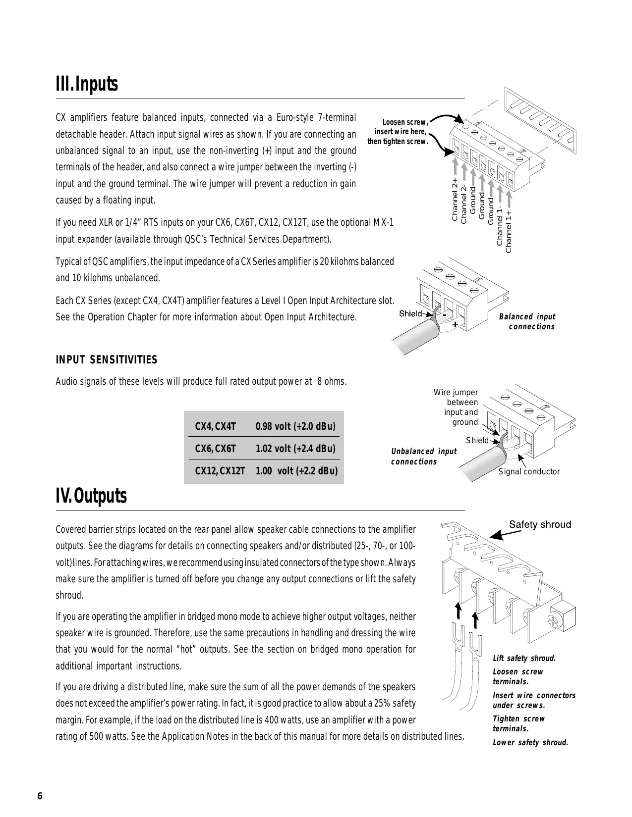
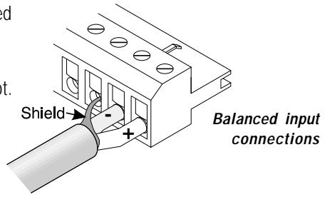
III. Inputs
CX amplifiers feature balanced inputs, connected via a Euro-style 7-terminal detachable header. Attach input signal wires as shown. If you are connecting an unbalanced signal to an input, use the non-inverting (+) input and the ground terminals of the header, and also connect a wire jumper between the inverting (-) input and the ground terminal. The wire jumper will prevent a reduction in gain caused by a floating input.
If you need XLR or 1/4" RTS inputs on your CX6, CX6T, CX12, CX12T, use the optional MX-1 input expander (available through QSC's Technical Services Department).
Typical of QSC amplifiers, the input impedance of a CX Series amplifier is 20 kilohms balanced and 10 kilohms unbalanced.
Each CX Series (except CX4, CX4T) amplifier features a Level I Open Input Architecture slot. See the Operation Chapter for more information about Open Input Architecture.

INPUT SENSITIVITIES
Audio signals of these levels will produce full rated output power at 8 ohms.
| CX4, CX4T | 0.98 volt (+2.0 dBu) |
| CX6, CX6T | 1.02 volt (+2.4 dBu) |
| CX12, CX12T | 1.00 volt (+2.2 dBu) |

IV. Outputs
Covered barrier strips located on the rear panel allow speaker cable connections to the amplifier outputs. See the diagrams for details on connecting speakers and/or distributed (25-, 70-, or 100-volt) lines. For attaching wires, we recommend using insulated connectors of the type shown. Always make sure the amplifier is turned off before you change any output connections or lift the safety shroud.
If you are operating the amplifier in bridged mono mode to achieve higher output voltages, neither speaker wire is grounded. Therefore, use the same precautions in handling and dressing the wire that you would for the normal "hot" outputs. See the section on bridged mono operation for additional important instructions.
If you are driving a distributed line, make sure the sum of all the power demands of the speakers does not exceed the amplifier's power rating. In fact, it is good practice to allow about a 25% safety margin. For example, if the load on the distributed line is 400 watts, use an amplifier with a power rating of 500 watts. See the Application Notes in the back of this manual for more details on distributed lines.

Lift safety shroud.
Loosen screw
terminals.
Insert wire connectors
under screws.
Tighten screw
terminals.
Lower safety shroud.
If your application calls for connecting an 8-ohm speaker and a distributed line to the same amplifier channel, the CX4T, CX6T and CX12T can do that. However, since most of the audio power is drawn by the direct-connected speaker, you must derate the distributed line; the distributed line should have a total power load of no more than one-fourth the amplifier's normal distributed line power rating. Make sure the direct-connected speaker can handle the 8-ohm power rating of the amplifier. See Applications Notes section for more details.

Output connections for CX , bridged mono mode.
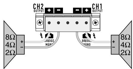
Output connections for CX , parallel or stereo mode.

Output connections for CXT, bridged mono mode.

Output connections for CXT, direct low impedance
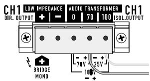
Output connections for CXT, 25 volt line.

Output connections for CXT, 70 volt line.

Output connections for CXT, 100 volt line.
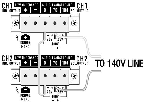
Output connections for CXT, bridged mono mode, 140 volt line.

Output connections for CXT, bridged mono mode, 200 volt line.
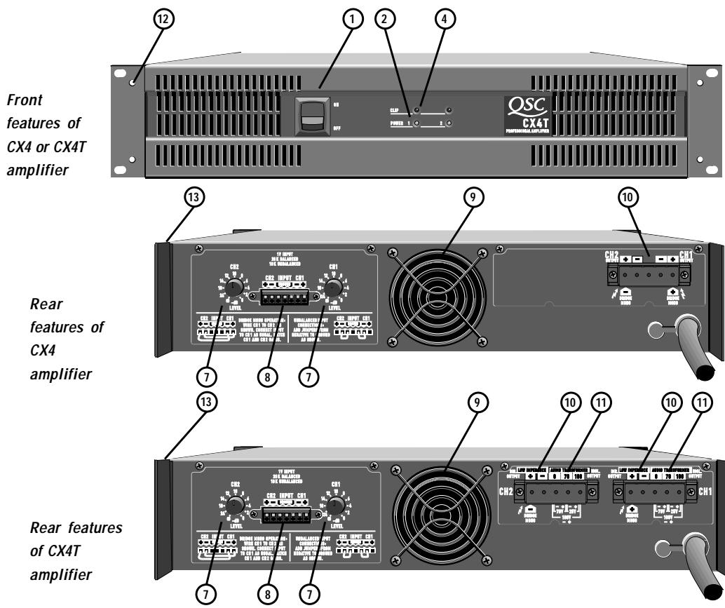
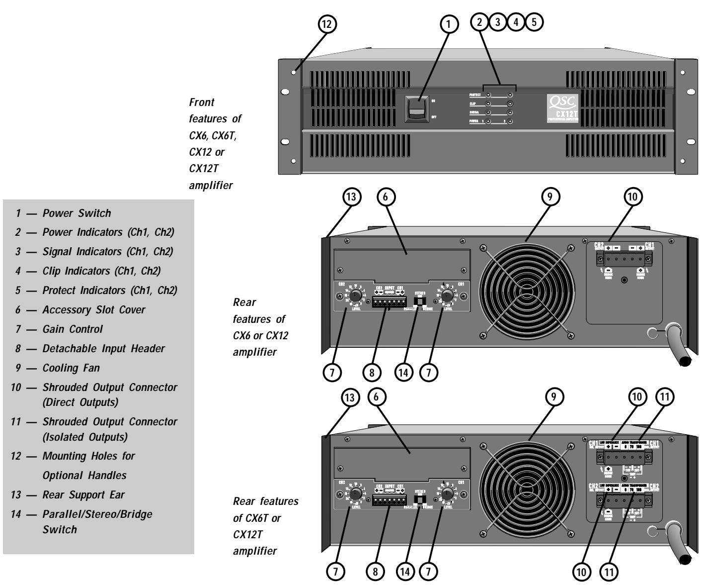
V. Controls & Displays
CX4 AND CX4T
The channel attenuator controls, labeled in dB of attenuation, are located on the rear panel. They have 11 detents, adjustable from 0 dB (full gain) to × (full attenuation). The LED displays for each channel function as shown at right.
CX6, CX6T, CX12, AND CX12T
The channel attenuator controls, labeled in dB of attenuation, are located on the rear panel. They have 11 detents, adjustable from 0 dB (full gain) to × (full attenuation). The LED displays for each channel function as shown at right.
VI. Operation
AC POWER
The amplifier is available for 100, 120, or 220-240 VAC, 50 or 60Hz operation. Unless it is specially ordered otherwise, each amplifier is configured for the line voltage in the market it is sold in. For example, those sold in Japan are 100 VAC; for North and Central America, 120 VAC; for Europe and most of Asia, 220-240 VAC.
The power cord has a plug for connecting to a standard AC source. For 120-volt operation, the plug is a standard 15-ampere grounded NEMA fitting; it meets safety agency requirements for current consumption of less than 12 amperes during "normal" operation, but peak current draw under heavy usage can be higher.
Models built for 220 to 240-volt use have a standard Schuko (continental Europe) connector on the power cable.
OPERATION
CX4 and CX4T
When first powering up, start with the gain controls off until proper operation is verified (upon turning on the AC switch, the "POWER" LED should come on, and after three seconds, the muting will stop and sound can be heard). The amp should now be working.
Gain should be kept in the upper half of its range for full performance. "POWER" LED indicators are provided to monitor the operation of each channel. Each channel has a red "CLIP" indicator that will show any distortion in the amplifier. The mute circuit should cut the sound off as soon as you turn off the amp, and mute for three seconds before restoring power to the speakers. This blocks turn-on and turn-off thumps.
LED Display for CX4 and CX4T:
NORMAL OPERATION
CLIP
POWER

OCCASIONAL CLIPPING
CLIP
POWER

STEADYCLIPPING
CLIP
POWER

LED Display for CX6, CX6T, CX12, and CX12T:
ON/OFF MUTING
PROTECT
CLIP
SIGNAL
POWER

O
NO SIGNAL
PROTECT
CLIP
SIGNAL
POWER


NORMAL SIGNAL
PROTECT
CLIP
SIGNAL
POWER


OCCASIONAL CLIPPING
PROTECT
CLIP
SIGNAL
POWER


STEADYCLIPPING
PROTECT
CLIP
SIGNAL
POWER


THERMAL MUTING
PROTECT
CLIP
SIGNAL
POWER


Full brightness
Flashing
Not illuminated
CX6, CX6T, CX12 and CX12T
When the amplifier is first turned on, the red "PROTECT" LED on each channel will light for about two or three seconds, during which the output relays will stay open to mute the speakers. After the turn-on muting interval, the "PROTECT" LEDs turn off, the green "POWER" LEDs light, and the output relays close to enable the speaker outputs. Even during the muting interval, the yellow "SIGNAL" and red "CLIP" LEDs operate normally if there is a signal present. If the "CLIP" LED is on while the amplifier is muted, cut the gain back immediately to avoid a full-power blast of sound when the output relays close. If a channel stays muted with "PROTECT" lit, or if its "SIGNAL" or "CLIP" indicators light up when the gain is turned all the way down, it may be defective; see the troubleshooting segment for more information.
The "SIGNAL" LED indicates signal levels that are -30 dB (referenced to full rated output power) or higher.
Whe the amplifier is shut off, the amplifier should mute both channels virtually instantaneously, with the "PROTECT" indicators lit until the power supplies are discharged.
TROUBLESHOOTING
Problem: Channel will not come out of muting
- If reducing the gain control to × attenuation does not release muting, the channel is defective or overheated (see "Overheating," below).
- If reducing the gain releases the muting, raise the gain back up slowly while you watch the "SIGNAL" and "CLIP" indicators; the problem may be an abnormal signal (with excessive ultrasonic energy, for example) that could otherwise damage your speakers.
PROBLEM: No sound (CX6/CX12)
Is the channel muted? (If the "PROTECT" indicator is lit, the channel is muted; see below.)
- Is the "SIGNAL" LED lit or flashing? (If so, the speaker is open or blown, there is an open circuit in the speaker wiring, or there is an open circuit in the internal output wiring of the amplifier.)
- If the "SIGNAL" indicator is dark, there is probably not enough signal, or even none at all. Try turning up the rear panel attenuators or boosting the signal level at the input.
- If the "SIGNAL" indicator shows little or no activity but the "CLIP" LED is lit or flashing, there is probably a short circuit in the speaker wiring, especially if the "PROTECT" indicator starts flashing. It is also possible, but less likely, that the channel's output relay is defective and will not open, thereby short-circuiting the channel output and producing the same symptoms.
PROBLEM: Channel goes into muting, with "PROTECT" LED on (CX6/CX12)
-
If the fan is running full speed, the channel probably suffers from severe overheating. Unless there is a blockage in the flow of cooling air, the channel should return to normal within a minute or so (see "Overheating," below).
-
If the fan is not running at full speed, or the channel does not reset to normal after a cool-down period, the muting is probably because of a DC fault or other amplifier failure, especially if the "SIGNAL" or "CLIP" indicators are lit even with the attenuator turned all the way down.
PROBLEM: Overheating
- The thermal management system on a CX Series amplifier features a two-speed fan that modulates the cooling air flow over the heatsinks in response to the cooling needs. If the air flow is blocked, however, or if the amplifier is overdriven into very low impedance loads, the amplifier could overheat even though the fan is running at full speed.
CX4 & CX4T
- At 85 12 C both channels will mute. The "POWER" LED will remain lit, although the "CLIP" indicator will be dark. The amplifier will remain this way until the temperature drops to a safe level.
CX6, CX6T, CX12 & CX12T
- At 85 12 C , the channel's output relay will mute the output. The channel will remain muted until the temperature drops to a safe level. Even while the channel is muted, the "SIGNAL" and "CLIP" indicators will function normally. If the "CLIP" indicator is flashing or continuously lit, reduce the gain to hasten the cool-down and prevent repeated thermal shutdowns.
PROBLEM: Hum in the audio
- Because of its grounded-collector output transistor configuration, which maximizes thermal efficiency, the signal ground on a CX amplifier cannot be lifted. The amplifier's balanced inputs are meant to reject hum, but if hum remains a problem, check the tightness of the two mounting screws on the input panel (except CX4 and CX4T); if they are loose, the panel itself might not be well grounded to the chassis. If you have any problems with these screws, contact the QSC Technical Services Department. In some cases, such as when the audio signal cables are routed near lighting dimmers that use triacs, you may need to use input isolation transformers because of the extremely high noise field produced by the dimmer circuitry. See the paragraphs on Open Input Architecture for further information on input transformers.
OPEN INPUT ARCHITECTURE™ LEVEL I (CX6, CX6T, CX12 and CX12T only)
On the rear of a CX amplifier are an upper and a lower input panel; both are easily removable for future upgrades. This is the concept of Open Input Architecture, and the opening in which the panels mount is called the "slot." As installed at the factory, the lower is the CX standard input panel and the upper one is a blank. A ribbon cable connects the "slot" panels to the rest of the amplifier. It carries input signals, speaker output monitor signals, mating status, and clip activity; these are for supporting future accessories and remote control systems. Although the physical dimensions of the CX, MXa, and EX panels are the same, their internal cabling is different and the CX platform supports most (but not all) of the MXa functions but doesn't support all of the EX functions. The CX and MXa Open Input Architecture slot thus is designated as "Level I" and the EX as "Level II."

The standard input panel installed on the CX Series amplifier has balanced Euro-style detachable header inputs, gain controls, and the Parallel-Stereo-Bridge switch. The panel's circuit board has solder footprints for passive roll-off circuit components, input isolation transformers, and other special customizations.
The MX-1 Input Expander panel may be installed in the upper panel position. It features XLR inputs and 1/4" RTS inputs. Installation instructions are included with the expansion kit.
Other available accessories include a universal filter and a stereo power limiter; more are in development. Contact QSC for more details before using accessories with CX amplifiers. See the CX Application Notes also.

Parallel
PARALLEL, STEREO, OR BRIDGED OPERATION (CX6, CX6T, CX12 and CX12T only)
The Parallel-Stereo-Bridge switch is located on the input panel. Always turn off the amplifier before changing the position of this switch.
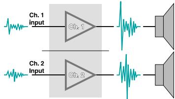
The most commonly used operating mode for a power amplifier is "Stereo," in which the two channels are independent and separate all the way from input to output. Set the switch in the center position for stereo operation.
Stereo
"Parallel" ties the two channel inputs together so that both will be driven by the same signal, without the need for external jumpers or wiring. After the inputs both channels operate independently; though they carry the same signal, their gain controls affect only their respective channels, and they must use separate speakers. Never parallel the speaker outputs!

Bridged Mono
The "Bridge" position uses both channels to provide about three times the power to a single speaker load that a single channel does. In this position, the switch feeds channel 2 with an inverted signal from channel 1. Thus, when one channel "pushes," the other "pulls," providing twice the voltage swing of a single channel.

BRIDGED-MONO MODE CAUTION:
ALL MODELS-Output voltages as high as 160 volts rms are available between the CX amplifier's bridged terminals (200 volts at isolated outputs).
CX4T, CX6T and CX12T (140V and 200V operation)—Fully insulated CLASS ONE wiring must be used to connect the amplifier to the loudspeakers
MODE BRIDGÉ MONO: ATTENTION
Instructions for bridged operation
CX4 and CX4T
- To engage the bridged mono mode, jumper the barrier strip inputs on the rear, in accordance with the diagram printed under the barrier strip inputs. Connect the amplifier input to channel 1 only, with the jumpers as shown to channel 2. Channel 1 and channel 2 gains must be matched. A 4, 8, or 16 ohm speaker load can be connected across the two red speaker terminals, using the red binding post of channel 1 for "+" or "hot."
CX6, CX6T, CX12 and CX12T
- Set the switch to the "Bridge" position.
- Connect the signal to channel 1's input only. Do not connect an input signal to channel 2. However, as a convenience for routing the same signal to multiple amplifiers without using Y connectors, the mode switch connects the channel 1 and channel 2 inputs in parallel. Therefore, you can use channel 2's input terminals to pass the audio signal on to other amplifiers.
- Use only channel 1's gain control to set the level. Both channels' "SIGNAL" and "CLIP" indicators should flash identically when the amplifier is operating.
- Connect the single speaker load across the + amplifier outputs as shown in the Outputs chapter. The positive speaker wire goes to channel 1, and the negative to channel 2.


MAXIMUM LONG-TERM OUTPUT POWER
In a properly designed sound system, you can obtain the desired sound level without using the full output power of the amplifier; if the "CLIP" indicators flash once in a while, that is perfectly normal.
If the amplifier is operated at extremely high power levels, it may overheat or may even damage the speakers. The amount of stress on the amplifier depends largely on the load and how hard the amplifier drives it. In general, the lower the load impedance, the more stressful the load is.
8-Ohm Loads and Lightly Loaded 25V, 70V, or 100V Lines
The amplifier can operate at practically any power level without risk of overheating. However, if it is pushed hard enough to continually light the "CLIP" indicator, the amplifier's average output power can reach 110 to 475 watts (depending on the model), which is more than many speakers can handle.
4-Ohm Loads and Heavily Loaded 25V, 70V, or 100V Lines
If the "CLIP" indicator flashes occasionally, the amplifier is approaching its maximum long-term power capacity. If it is lit about half the time, the amplifier channel will probably go into thermal protection within a few minutes.
2-Ohm Loads
Except for an occasional flash, keep the "CLIP" indicator dark to avoid overheating the amplifier channel.
AC CURRENT CONSUMPTION
A major objective in the design of the CX Series amplifiers-even the higher-powered models-is to permit their operation from readily available, standard AC power sources.
"Normal conditions" in power amplifier rating means operating with a random program source (pink noise), using pink noise as a source, at an average power level equal to one-eighth of maximum power. This is recognized by most of the world's safety agencies as the loudest you can play music through an amplifier and still keep the incidence of clipping to a reasonable minimum. An amplifier's peak current draw at full output power into 2 ohms is several times what the "normal" draw is, but its various protection circuits will prevent this condition from lasting more than a minute or two.
When you plan the AC power hookups for your amplifiers, use the table in the Specifications section to predict the current requirements per amplifier. You can use the one-eighth power figures to predict the normal continuous current draw, then add a safety margin to allow for occasional crescendos.
HEAT EMISSIONS
Essentially, a power amplifier draws electrical energy from the AC mains, converts it to DC, and then converts it again into an analog of the input signal to send out to the loudspeakers. Any AC power that enters the amplifier through the power cord and does not exit through the speaker outputs turns into heat, which the amplifier must rid itself of by exhausting it to the outside. In indoor use this may present a sizeable challenge to a building's air conditioning system. Use the table below to predict the heat that will be emitted by your amplifier.
| Model | Full Power | 1/3 Power | 1/8 Power | Idle | |||||
| Channel Load | BTU/hr kcal/hr | BTU/hr kcal/hr | BTU/hr kcal/hr | BTU/hr kcal/hr | |||||
| CX4, CX4T | 8Ω + 8Ω | 645 | 163 | 615 | 155 | 510 | 128 | 85 | 22 |
| 4Ω + 4Ω | 1265 | 318 | 1060 | 267 | 830 | 210 | 85 | 22 | |
| 2Ω + 2Ω | 2340 | 590 | 1700 | 429 | 1295 | 326 | 85 | 22 | |
| 70V + 70V | 1365 | 344 | 1050 | 264 | 800 | 202 | 85 | 22 | |
| CX6, CX6T | 8Ω + 8Ω | 1406 | 354 | 1020 | 257 | 604 | 152 | 229 | 58 |
| 4Ω + 4Ω | 2525 | 637 | 1617 | 408 | 921 | 232 | 229 | 58 | |
| 2Ω + 2Ω | 4658 | 1174 | 2532 | 638 | 1290 | 325 | 229 | 58 | |
| 70V + 70V | 2010 | 507 | 1503 | 379 | 1141 | 288 | 229 | 58 | |
| CX12, CX12T | 8Ω + 8Ω | 1791 | 452 | 1239 | 312 | 805 | 203 | 297 | 75 |
| 4Ω + 4Ω | 3330 | 840 | 2081 | 525 | 1222 | 308 | 297 | 75 | |
| 2Ω + 2Ω | 5698 | 1437 | 3146 | 793 | 1611 | 406 | 297 | 75 | |
| 70V + 70V | 3772 | 951 | 2338 | 589 | 1280 | 323 | 297 | 75 | |
Heat emissions of CX amplifiers under various conditions
PROTECTION CIRCUITS
The design goal in high-efficiency amplifiers such as the CX Series is to increase the amplifier's ability to deliver peak power without increasing its size, weight, and cost. However, the higher power flow through the output components makes effective, responsive protection circuitry absolutely vital. To this end, the design of the CX series takes a comprehensive approach to protection.
As in all QSC amplifiers, the inputs are resistively buffered for overload and RF protection. Chassis bypass capacitors at inputs and outputs further improve RF rejection.
CX amplifiers use the proven Output Averaging™ short circuit protection system. This circuit permits full output current even into resistive or reactive 2-ohm loads, but reduces the current safely by about 75% if the output is shorted.
Turn-on/turn-off mating keeps transients-both from the amplifier itself and from upstream equipment-from reaching the speakers when the amplifier is turned on or off. The turn-on delay is approximately three seconds to allow the power supplies and circuitry to stabilize. Turn-off mating occurs almost immediately after power is shut off. Muting occurs whether power is turned on and off using the front panel power switch or externally at the AC source.
Inside a CX6, CX6T, CX12, or CX12T amplifier, an NTC (negative temperature coefficient) thermistor in series with the power switch and transformer primary limits intrush current. The thermistor initially has a high resistance, which then diminishes rapidly as it warms, to avoid power loss. Typically, the intrush current of an CX Series amplifier thus is equal to that of another amplifier of about 1/3 to 1/2 its power rating. The low intrush of the smaller CX4 and CX4T does not require an NTC thermistor.

When the DC fault protection circuitry of a CX6, CX6T, CX12, or CX12T senses a DC voltage on a channel output, it actuates a relay which shorts the output and load to ground. The amplifier's Output Averaging protection circuitry will limit current to further protect the output devices. If the DC problem persists, that channel will go into thermal protection mode and should be serviced by a qualified technician.
The output stage of a CX4 or CX4T channel has AC coupling to prevent it from passing DC.
Temperature sensors on the channel heatsinks and the power transformers are part of the thermal management circuitry. The temperature sensors govern whether the dual-speed fan should run at low or high speed. Below 5512C , the fan runs at low speed; above, it runs at high speed. At or above 8512C , the channel mutes to go into thermal protection.
Built-in second-order 50 Hz (CX4T) and third-order 45 Hz (CX6T and CX12T) Butterworth high-pass filtering helps prevent saturation in speaker transformers on distributed lines by sharply reducing the amount of ultra-low frequency energy the amplifier puts out. However, some lower-quality speaker transformers have rated low-frequency responses that do not even extend as low as these filters; if you have any of these in your distributed line system you should insert corresponding high-pass filtering in the audio path before the amplifier.
VII. Specifications
| CX4 | CX4T | CX6 | CX6T | CX12 | CX12T | |
| POWER OUTPUT | ||||||
| Direct output, watts per channel, both channels driven | ||||||
| 8Ω, 20 Hz–20 kHz, 0.1% THD | 150 | 200 | 400 | |||
| 8Ω, 45 Hz–20 kHz, 0.1% THD** | 150 | 200 | 400 | |||
| 8Ω, 1 kHz, 1% THD | 170 | 170 | 220 | 220 | 475 | 475 |
| 4Ω, 20 Hz–20 kHz, 0.1% THD | 225 | 300 | 600 | |||
| 4Ω, 45 Hz–20 kHz, 0.1% THD** | 225 | 300 | 600 | |||
| 4Ω, 1 kHz, 1% THD | 270 | 270 | 350 | 350 | 700 | 700 |
| 2Ω, 1 kHz, 1% THD* | 350 | 350 | 450 | 450 | 900 | 900 |
| Isolated outputs, watts per channel, both channels driven | ||||||
| 70V or 100V, 45 Hz–16 kHz, 0.25% THD** | 175 | 250 | 500 | |||
| 25V, 45 Hz–16 kHz, 0.25% THD** | 150 | 200 | 400 | |||
| Direct Outputs, bridged mono | ||||||
| 8Ω 20 Hz–20 kHz, 0.1% THD | 450 | 600 | 1200 | |||
| 8Ω, 45 Hz–20 kHz, 0.1% THD** | 450 | 600 | 1200 | |||
| 4Ω, 1 kHz, 1% THD* | 700 | 700 | 900 | 900 | 1800 | 1800 |
| Isolated outputs, bridged mono | ||||||
| 50V, 45 Hz–16 kHz, 0.25% THD** | 300 | 400 | 800 | |||
| 140V, 45 Hz–16 kHz, 0.25% THD** | 350 | 500 | 1000 | |||
| 200V, 45 Hz–16 kHz, 0.25% THD** | 350 | 500 | 1000 | |||
| *typical | ||||||
DISTORTION
SMPTE-IM, less than 0.05%
CX4T direct outputs: -3 dB @ 50 Hz, -0.2 dB @ 20 kHz
CX4T isolated outputs: 50Hz - 16kHz, + 0, - 3dB
CX6T, CX12T direct outputs: -3 dB @ 45 Hz, -0.2 dB @ 20 kHz
CX6T, CX12T isolated outputs: 45 Hz-16 kHz, +0, -3 dB
**Low frequency response on "T" versions is limited by 18 dB/octave 45-Hz high-pass filter. Low frequency response on CX4T versions is limited by 12 dB/octave 50-Hz high-pass filter.
DAMPING FACTOR
200 (@ direct outputs)
OUTPUT REGULATION
100V 1.0 dB 1.0 dB 1.1 dB
70V 1.1 dB 1.1 dB 1.2 dB
25V 2.0 dB 2.0 dB
NOISE
100 dB below rated output (20 Hz to 20 kHz)
VII. Specifications (cont.)
| CX4 | CX4T | CX6 | CX6T | CX12 | CX12T | |
| VOLTAGE GAIN @ direct outputs: | 35× (31 dB) | 35× (31 dB) | 40× (32 dB) | 40× (32 dB) | 56.5× (35 dB) | 56.5× (35 dB) |
| INPUT SENSITIVITY, VRMS for rated power, 8 ohms | 0.98 | 0.98 | 1.03 | 1.03 | 1.043 | 1.043 |
INPUT IMPEDANCE
10K unbalanced, 20K balanced
CONTROLS
Front: AC Switch
Rear: Parallel/Stereo/Bridge Switch (except CX4, CX4T)
Ch.1 and Ch.2 Attenuator Knobs (11 detents: 0, -2, -4, -6, -8, -10, -12, -14, -18, -24, off)
FRONT PANEL/INDICATORS (per channel)
PROTECT: Red LED (except CX4, CX4T)
CLIP: Red LED
SIGNAL: Yellow LED (except CX4, CX4T)
POWER: Green LED
REAR PANEL/CONNECTORS (each channel)
Input: Euro-style detachable header
Output: Covered barrier strips
COOLING
2-speed fan, with back-to-front air flow
AMPLIFIER PROTECTION
Output Averaging™ short circuit protection, open circuit, ultrasonic, RF, thermal mating.
Stable into reactive or mismatched loads.
LOAD PROTECTION
Turn-on/turn-off muting, DC-fault load grounding relay with internal fault fuses.
OUTPUT CIRCUIT TYPE
CX4, CX4T, CX6, CX6T: Class AB complementary linear stage
CX12, CX12T: Class H complementary linear stage, with 2-step high-efficiency circuit
POWER REQUIREMENTS:
100, 120, 220-240 VAC, 50/60 Hz
POWER CONSUMPTION (see chart on page 13)
Normal operation: 1/8 power @ 4Ω per channel
Worst case continuous program: 1/3 power @ 2Ω per channel
Maximum: full power @ 2Ω per channel
Multiply current times 0.5 for 220-240 VAC operation
| Model | Channel Load | AC Current, Full Power | AC Current, 1/3 Power | AC Current, 1/8 Power | AC Current, Idle |
| CX4, CX4T | 8Ω + 8Ω | 5.7 A | 3.4 A | 2.3 A | 0.4 A |
| 4Ω + 4Ω | 9.2 A | 5.2 A | 3.5 A | 0.4 A | |
| 2Ω + 2Ω | 13.3 A | 7.4 A | 4.9 A | 0.4 A | |
| 25V, 70V, 100V | 8.7 A | 5.0 A | 3.3 A | 0.4 A | |
| CX6, CX6T | 8Ω + 8Ω | 7.7 A | 4.9 A | 3.3 A | 0.6 A |
| 4Ω + 4Ω | 12.5 A | 7.4 A | 4.8 A | 0.6 A | |
| 2Ω + 2Ω | 18.8 A | 11.0 A | 7.2 A | 0.6 A | |
| 25V, 70V, 100V | 11.2 A | 6.7 A | 4.5 A | 0.6 A | |
| CX12, CX12T | 8Ω + 8Ω | 14.7 A | 8.4 A | 4.5 A | 0.8 A |
| 4Ω + 4Ω | 23 A | 12.4 A | 6.1 A | 0.8 A | |
| 2Ω + 2Ω | 33 A | 16.5 A | 8.0 A | 0.8 A | |
| 25V, 70V, 100V | 21 A | 10.9 A | 5.7 A | 0.8 A |
DIMENSIONS
Faceplate Width Standard 19" (48.3 cm) Rack Mounting
Chassis Depth 17.9" (45.5 cm) deep (to rear support ears)
FaceplateHeight CX4 & CX4T: 3.5" (13.3 cm)
CX6 & CX6T; CX12 & CX12T: 5.25" (13.3 cm)
| WEIGHT | CX4 | CX4T | CX6 | CX6T | CX12 | CX12T |
| Shipping | 33 lb; 16.4 kg | 42 lb; 21 kg | 49 lb; 24 kg | 62 lb; 28 kg | 58 lb; 26.3 kg | 75 lb; 34 kg |
| Net | 27 lb; 13.6 kg | 37 lb; 18.2 kg | 42 lb; 20 kg | 55 lb; 25 kg | 50 lb; 22.7 kg | 67 lb; 30.4 kg |
Part 2—CX Series Application Guide

ith the helpful advice and input from contractors and consultants around the world, engineers at QSC designed the CX Series amplifiers to be a versatile and reliable foundation for high-quality installed sound systems.
This applications guide will help you design your sound system properly and utilize your CX amplifier(s) effectively.
VIII. Distributed lines
The best way to distribute audio power from a common amplifier among numerous relatively low-powered loudspeakers is to use a distributed line, whether all the loudspeakers are meant to receive the same or different power levels.
A distributed line is usually referred to by its maximum voltage-25-, 70-, 100-, or 140-volt lines are most common. An amplifier's power rating is determined by how much current it can put out at a standard voltage level; a low-power 70-volt amp has less current capability than a high-powered 70-volt amp, even though they can both put out the same voltage. The high-powered amp can drive more speakers and at higher power levels than the lower-powered one can. This is somewhat analogous to AC electrical distribution, where you might have circuits rated for 15A, 20A, 30A, etc., at 120 or 240 VAC, and you can connect any
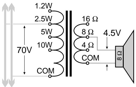
Example of a loudspeaker connected to a distributed line through a transformer
number of appliances to them as long as you don't exceed the circuit's current capacity.

Loudspeakers on a distributed line use tapped transformers to match their power requirements to the line. A loudspeaker with a 70-volt transformer tapped at 2 watts, for example, will receive that amount of power when the amplifier puts out 70 volts on the distributed line. Transformer taps are usually set at 3 dB intervals, i.e., each successive tap is twice the power level of its predecessor. An example would be a transformer tapped at 0.5, 1, 2, and 4 watts. This allows you to select a power level that is most appropriate for the situation while still retaining the versatility of configuring other loudspeakers on the same line for different power levels.
Example of a 70 volt distributed line
IX. Designing the Distributed Sound System
There are several main steps in designing a distributed sound system:
Determining loudspeaker coverage and placement
Determining power levels for each loudspeaker
- Choosing the right amplifier
LOUDSPEAKER COVERAGE AND PLACEMENT
The goal in placing the loudspeakers in a distributed system is to acoustically cover the required area effectively but economically. An effective coverage would be one where the sound from the system's loudspeakers is not only audible, but intelligible, over all of the area. An economical coverage would be one that achieves the goal with the fewest loudspeakers necessary.
A loudspeaker in a partially or fully enclosed area produces two sound fields: the direct field, which is sound coming directly "line-of-sight" from the loudspeaker; and the diffuse field, which is sound from the loudspeaker which has reflected off of surfaces in the area, such as floors, walls, tables, ceilings, etc. The direct sound field decreases with distance from the loudspeaker; every time you double the distance, the sound pressure level drops 6 dB. This is called the Inverse Square Law because the result of a 6 dB sound pressure level decrease is the same as 1/4 of the sound intensity (i.e., the sound power per square centimeter), which varies inversely with the square of the distance.
Even though it too is subject to the Inverse Square Law, the intensity of the diffuse field is more difficult to predict, especially with multiple acoustically reflective surfaces. The problem
is that moving away from one surface may also be moving closer to another. Controlling the diffuse field often involves architectural planning as well as acoustical treatment with absorptive surface materials.
To maintain intelligibility, maximize the ratio of direct field to diffuse field; this generally involves placing the loudspeakers as close to the listeners as is both physically and economically practical.
Sometimes, a distributed line system can help a coverage area with difficult acoustical characteristics. For example, a very reverberant room with all large hard,

reflective surfaces—wood floors and ceiling, concrete and plaster walls, etc., the type of room that tends to make speech unintelligible—might benefit from using many low-powered loudspeakers placed throughout the room and close to the listeners, instead of using a couple high-powered, centrally-located loudspeakers.
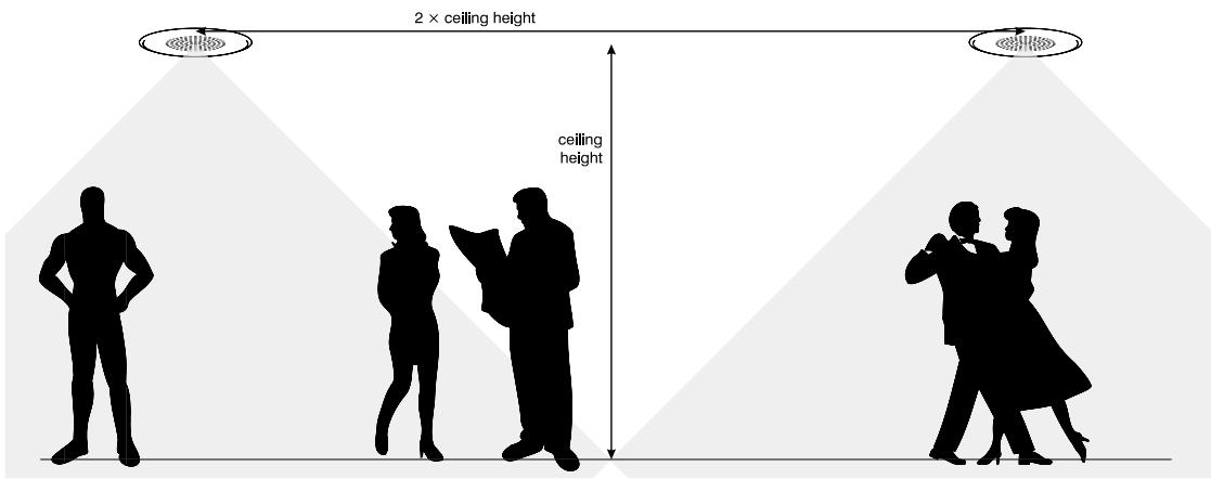
With ceiling-mounted loudspeakers, one general rule of thumb is to make the center-to-center distance between them no greater than twice the floor-to-ceiling distance. Used with loudspeakers that have a 90^ angle of coverage, this is often suitable for background music systems, but for paging and public address applications it leaves some erratic coverage at listening positions higher than floor level.
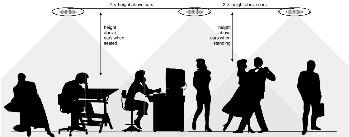
A better technique is to space the ceiling speakers at twice the distance from the listeners' ears to the ceiling. This requires more loudspeakers spaced closer together than the previous scheme does, but provides good, uniform coverage at realistic listening positions. In a room where people are standing, you'll need closer spacing than if people tend to be sitting. For example, if a lunchroom has a ceiling height of 2.9 meters (9.5 feet), and the height of an average listener's ear, when seated, is about 1.1 meter (3.5 feet) above the floor (and therefore about 1.8 meter or 6 feet from the ceiling), then you should space the loudspeakers no more than 3.6 meters, or about 12 feet, apart.
Even better, more uniform coverage will result from spacing the loudspeakers at 1.5 times the ceiling-to-ear distance. In the above example, this would require spacing the loudspeakers about 2.7 meters (9 feet) apart.
DETERMINING POWER LEVELS
After you've determined where to place the loudspeakers, you need to calculate the power each one requires. If the installation is in an existing facility already in use, use an SPL meter, set for slow response, to measure
the A weighted ambient noise at the listener's ear position. Try to take this measurement at the noisiest time—in a factory, when the machines are running; in a restaurant, when it's full of patrons, etc. Background music will require an SPL at least 10 dB above the ambient noise. For good paging intelligibility, you'll need an SPL approximately 15 dB higher than the ambient noise; 25 dB above ambient will yield excellent intelligibility.
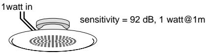
Next, use the distance from the loudspeaker to the listener's ears, along with the loudspeaker's sensitivity rating (typically expressed as "n dB @ 1 watt, 1 meter," which means n dB of SPL with 1 watt input, measured at a distance of 1 meter) to determine how much power the loudspeaker needs to get from the distributed line. Use the inverse square law guide below to convert distance to dB; you'll need to add this figure to the desired SPL and then subtract the sensitivity rating to determine how much more or less than 1 watt the loudspeaker requires.
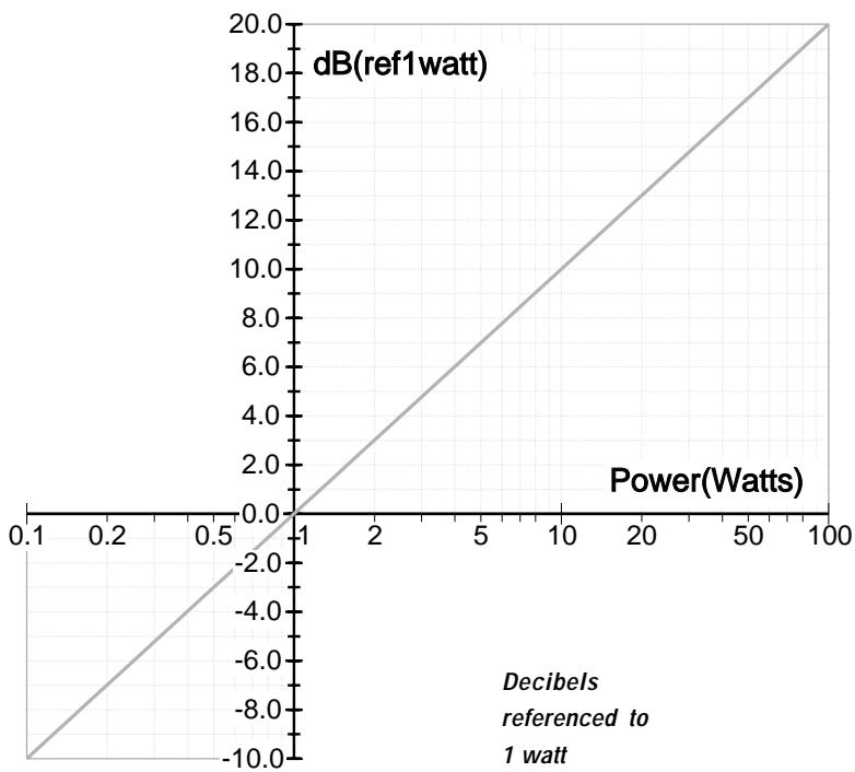
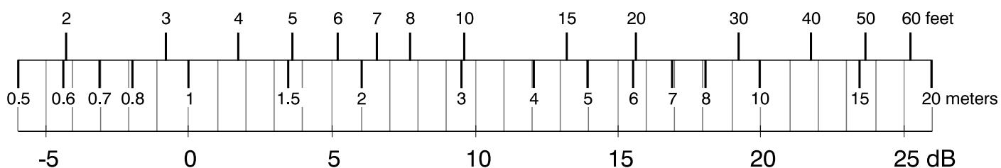
Distance from speaker
(ref: 1 meter, or 3.28 feet)
Power increase in dB; referenced to loudspeaker
sensitivity rating (1 watt @ 1 meter)
EXAMPLE
A loudspeaker (sensitivity: 94 dB @ 1W, 1 meter) in a busy office covers an area with an ambient noise of 72 dBA, measured at a seated person's ear position at the desks. The client wants superb intelligibility, so your goal is to provide an SPL of 97 dB (72 plus 25) to the intended listeners. The ceiling-mounted speaker is about 6 feet, or 1.8 meters, above the listeners' ears. The dB figure from the inverse square law conversion guide for that distance is 5.2 dB; this means that the loudspeaker would have to produce 102.2 dB (97 plus 5.2) at a distance of 1 meter to achieve 97 dB at a distance of 1.8 meters.
The loudspeaker will require a power level 8.2 dB (102.2 minus 94) greater than 1 watt; this works out to 6.6 watts. The speaker transformer taps are 0.5, 1, 2, 4, and 8 watts; the closest choice would be the 8-watt tap, which turns out to be only 0.8 dB higher than the design ideal.
SELECTING THE AMPLIFIER
After you've determined the power taps for each loudspeaker transformer, add them up. The sum will be what you determine your amplifier requirements from. If you have 16 loudspeakers tapped at 2 watts, seven at 1 watt, and eight at 10 watts, the total audio power the loudspeakers want is 119 watts.
Thanks to a transformer phenomenon called insertion loss, though, your amplifier needs to provide more power than the loudspeakers will draw. High-quality speaker transformers typically have an insertion loss of about 1 dB, meaning that it takes about 1.25 watt going into the transformer to put 1 watt into the loudspeaker. A lower-quality transformer may have a loss of 2 dB, which requires approximately 1.6 watts for every watt that the loudspeaker receives. Poor-quality transformers may have even higher losses, but they will probably degrade the system's audio performance severely even if there is adequate amplifier power to overcome the losses.
To compensate for the insertion loss, add a corresponding percentage to the sum of the transformer power taps. For transformers with a 1 dB loss, add about 25% ; in the example above, that would increase 119 watts up to 149 watts.
Next, it is a good engineering practice to add another 25% to the figure. This allows a margin both for dynamic audio headroom and for some future adjustments to the system—an added speaker or two, a few transformer tap changes, etc. That would bring the total power requirement for the example system up to 186 watts. This would be the minimum power rating for the amplifier you choose.
INSTALLATION TIP:
Once the sound system is installed and operational, turn the amplifier off and take an impedance measurement across the distributed line at the amplifier output, using an audio impedance meter (not an ohmmeter). Record the measurement for later use. If you ever have to make a service call on the system, measure the impedance again and see how it compares to the recorded figure; it's a quick and easy way to see if anything in the distributed line system has been changed. Likewise, measure the impedance anytime you've changed a transformer tap, added or removed a loudspeaker, or made any other adjustment to anything on the distributed line.
USING COMPONENTS WITH DIFFERENT VOLTAGES
Sometimes it may be practical to use a transformer or loudspeaker/transformer combination with a different voltage system from what it was originally intended. For example, a 70-volt transformer could be used in a 25-volt system, although you would have to derate the power taps similarly. Never use a transformer with a higher voltage than what it is designed for, though; i.e., you couldn't use that same transformer on a 100- or 140-volt line.
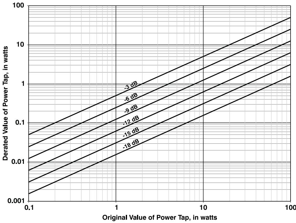
To properly derate the transformer tap power levels, locate the column with the voltage the transformer is rated for in the table below, then locate the row with the system voltage you want to use it in. The table will indicate the dB reduction to use with the derating chart below it.
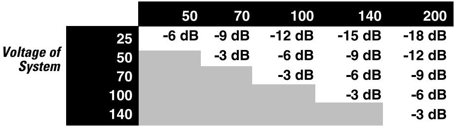
Voltage Rating of Transformer
EXAMPLE
You have a 70-volt transformer with taps labeled 0.6, 1.2, 2.5, and 5 watts. What power points will those taps provide on a 50-volt line?
The table shows that 50 volts is 3 dB less than 70 volts. The chart confirms that the taps will provide 0.3, 0.6, 1.25, and 2.5 watts, respectively.
X. How Many Speakers?
How many loudspeakers can you connect to the distributed line? The amplifier itself determines the amount of audio power available to the line, and from that figure you must compensate for insertion loss in the speaker
transformers and for headroom when you determine how much power is available for the speakers.
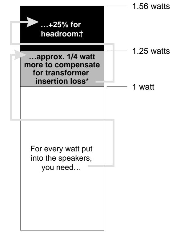
*assuming a typical insertion loss of 1dB †a good engineering practice
For example, let's suppose you have an amplifier rated at 500 watts into a 70-volt line, and your speaker transformers each have an insertion loss of 1 dB, which is typical. The losses in the transformers mean that they will draw 25% more audio power than they deliver to the speakers. For headroom, as mentioned before, you add at least another 25% to the total amount of power drawn from the amplifier. The additional 25% headroom is optional but highly recommended. It will allow for future additions to the system and reduce the stress on the power amplifier.
$$ 1. 2 5 \times 1. 2 5 = 1. 5 6 2 5 $$
So you'll need at least about 56 % more power than the total sum of the transformer taps. The reciprocal of 1.5625 is .64, so conversely you can figure on allowing a maximum of 64 % of the amplifier's rated power for the loudspeakers. Therefore, the highest combination of transformer taps the 500- watt amplifier can drive satisfactorily is a sum of about 320 watts, e.g., 32 speakers each tapped at 10 watts, or 64 speakers tapped at 5 watts, etc.
This table lists the recommended maximum load (sum of all speaker transformer power taps on one line) for the CX6T and CX12T amplifiers. These figures assume a typical transformer insertion loss of about 1 dB.

CX/T Recommended Maximum Power by distributed line application
You can, of course, use different output configurations on the two amp channels if it's not operating in bridged mono mode. For example, one channel of a CX12T could drive a 70-volt line loaded at 320 watts while the other channel drives a 25-volt line, or even a direct loudspeaker.
SPEAKER TRANSFORMER SATURATION
Speaker transformers tend to be fairly small, and some vary widely in quality. They tend, therefore, to be prone to core saturation at low frequencies. Saturation occurs when the magnetic field induced in the transformer's iron core by the audio signal waveform has built up as high as the core can handle. Even if the signal voltage increases, the magnetic flux cannot increase any further, so it "clips," in a way. High frequencies are less likely to cause saturation because the signal waveforms, rapidly alternating in polarity, reverse the direction of the magnetic flux before saturation can occur.
Saturation causes audible distortion. In extreme cases it can damage the power amplifier driving the line, because as the transformers go out of saturation, their magnetic fields collapse and induce a voltage spike across the line. That voltage spike travels along the line back to the amplifier, which has to absorb it. Interestingly, this phenomenon is much more likely to happen on a lightly loaded line than on a heavily loaded one.
An effective way to eliminate the saturation problem is to filter out the frequencies most likely to cause it, without adversely affecting the audio quality. The CX6T and CX12T both have built-in 45 Hz high-pass filters with an 18 dB per octave bass roll-off, while the CX4T has a 50 Hz high-pass filter with a 12 dB per octave roll-off. This is adequate prevention for virtually all good-quality speaker transformers. However, if any speaker transformers on the line do not have low-frequency responses that extend down to 45 Hz, you must insert corresponding high-pass filtering in the audio signal path before the amplifier.
CONNECTING BOTH A DISTRIBUTED LINE AND A DIRECT LOUDSPEAKER ON ONE CHANNEL
The T versions of the CX amplifiers have simultaneous direct outputs (for loudspeakers) and 25-, 70-, and 100-volt isolated outputs (for distributed lines). This adds a measure of versatility that few other amplifiers can match: being able to drive both a loudspeaker and a distributed line on a single channel at the same time.
Setting up such an arrangement is simple, but it requires some precautions:
- Use an 8-ohm speaker for the direct connection. Make sure it has an adequate power rating (150 watts for use with the CX4T, 200 watts for use with the CX6T; 400 watts for the CX12T). Connect it across the low impedance outputs.
- The distributed line must not be loaded any higher (sum of transformer taps plus allowance for insertion loss plus allowance for headroom) than 40 watts for the CX4T, 60 watts for the CX6T, or 125 watts for the CX12T. Connect it across the appropriate transformer terminals.
The directly connected speaker will constitute most of the load on the amplifier channel, so it will receive considerably more power than the distributed line. If you adjust the amplifier gain controls to vary the sound level from the directly connected
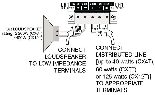
speaker, it will affect the sound level from the distributed line's speakers also, possibly altering them from your intended levels.
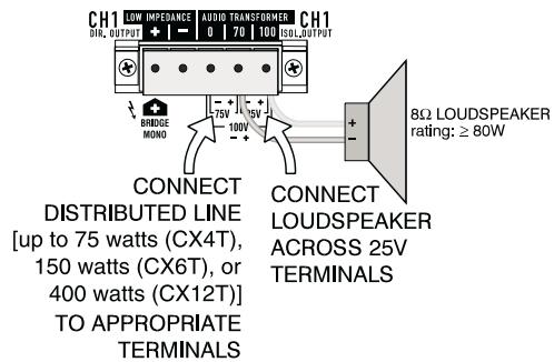
An alternate method is to attach an 8-ohm speaker across the 25-volt outputs. This provides up to approximately 80 watts to the speaker and makes more power available to the 70V or 100V connections: up to 75 watts for the CX4T, up to 150 watts for the CX6T; up to 400 watts for the CX12T.
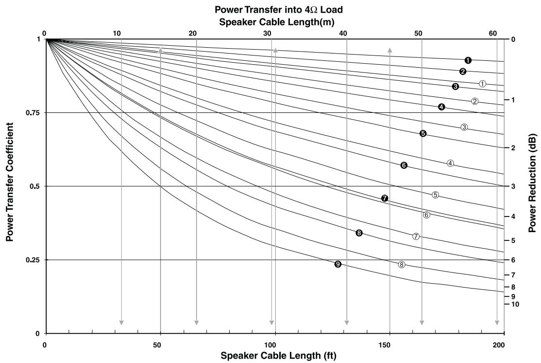
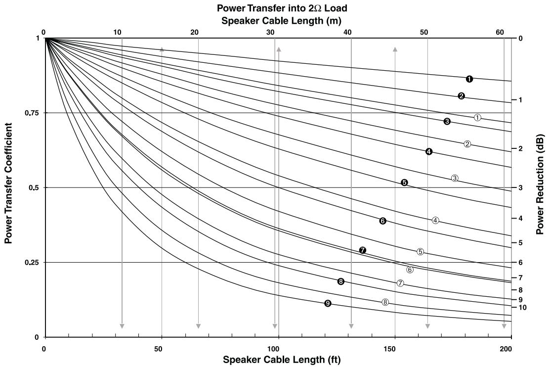
WIRE LOSS
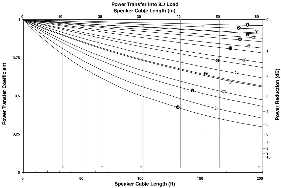
Even the highest-quality copper wire has a small amount of resistance to electrical current flow, and the wire's resistance is inversely proportional to the cross-sectional area of its conductor. Therefore, to minimize the power lost to speaker cable resistance, you should use the largest stranded (always stranded) copper wire that is practical for the job. This is especially important with direct low-impedance speaker connections; e.g., a half-ohm wire resistance would not affect a lightly-loaded 100-volt line noticeably, but it would reduce the amount of power going to a 2-ohm load by 36% , a 1.9 dB drop. It would also reduce the damping factor to no better than 4.
If an amplifier could drive a speaker load through theoretical zero-resistance wire, no power would be lost in the speaker cables. In the charts below we'll compare the power delivered through real-world speaker cables with the theoretical zero-resistance ideal and express it as a ratio called the power transfer coefficient. It is determined by the formula
$$ \text {P O W E R T R A N S F E R C O E F F I C I E N} = \left[ R _ {\text {L O A D}} / \left(R _ {\text {W I R E}} + R _ {\text {L O A D}}\right) \right] ^ {2} $$
Let's say you have an 8-ohm speaker load. With that imaginary zero-resistance wire, all the power would be delivered to the load, so the power transfer coefficient would be 1. If you then substituted wire with 0.2 ohm of resistance, the load would only get 95.2% of the power it got with the zero-ohm wire, so the power transfer coefficient would be 0.952 (a loss of 0.2 dB, by the way).
| AWG sizes | Metric sizes |
| ① 6 AWG | ① 6 mm² |
| ② 8 AWG | ② 4 mm² |
| ③ 10 AWG | ③ 2.5 mm² |
| ④ 12 AWG | ④ 1.5 mm² |
| ⑤ 14 AWG | ⑤ 1 mm² |
| ⑥ 16 AWG | ⑥ 0.8 mm² |
| ⑦ 18 AWG | ⑦ 0.6 mm² |
| ⑧ 20 AWG | ⑧ 0.4 mm² |
| ⑨ 22 AWG |
| AWG sizes | Metric sizes |
| ① 6 AWG | ① 6 mm² |
| ② 8 AWG | ② 4 mm² |
| ③ 10 AWG | ③ 2.5 mm² |
| ④ 12 AWG | ④ 1.5 mm² |
| ⑤ 14 AWG | ⑤ 1 mm² |
| ⑥ 16 AWG | ⑥ 0.8 mm² |
| ⑦ 18 AWG | ⑦ 0.6 mm² |
| ⑧ 20 AWG | ⑧ 0.4 mm² |
| ⑨ 22 AWG |
AC CURRENT CONSUMPTION
A major objective in the design of the CX Series amplifiers—even the higher-powered models—is to permit their operation from readily available, standard AC power sources.
"Normal conditions" in power amplifier rating means operating with a random program source (pink noise), using pink noise as a source, at an average power level equal to one-eighth of maximum power. This is recognized by most of the world's safety agencies as the loudest you can play music through an amplifier and still keep the incidence of clipping to a reasonable minimum. An amplifier's peak current draw at full output power into 2 ohms is several times what the "normal" draw is, but its various protection circuits will prevent this condition from lasting more than a minute or two.
When you plan the AC power hookups for your amplifiers, use the following table to predict the current
AC Current Consumption
| Model | 8Ω | 4Ω or Distributed Line | 2Ω | |||||||
| IDLE | FULL POWER | 1/3 POWER | 1/8 POWER | FULL POWER | 1/3 POWER | 1/8 POWER | FULL POWER | 1/3 POWER | 1/8 POWER | |
| CX4, CX4T | 0.4A | 6.0A | 2.8A | 2.5A | 10A | 4.5A | 3.8A | 15A | 6.8A | 5.6A |
| CX6, CX6T | 0.9A | 7.9A | 4.3A | 3.2A | 13A | 7.5A | 5.0A | 19A | 10A | 7.0A |
| CX12, CX12T | 1.0A | 15A | 8.6A | 5.1A | 24A | 12A | 6.5A | 33A | 17A | 8.5A |
requirements per amplifier. You can use the one-eighth power figures to predict the normal continuous current draw, then add a safety margin to allow for occasional crescendos.
HEAT EMISSIONS
Essentially, a power amplifier draws electrical energy from the AC mains, converts it to DC, and then converts it again into an analog of the input signal to send out to the loudspeakers. Any AC power that enters the amplifier through the power cord and does not exit through the speaker outputs turns into heat, which the amplifier must rid itself of by exhausting it to the outside. In indoor use, multiple amplifiers may present a sizeable challenge to a building's air conditioning system. Use the table below to predict the heat that will be emitted by your amplifier. Use one-eighth power for normal, continuous usage.
Heat Emissions
| Model | 8Ω | 4Ω or Distributed Line | 2Ω | |||||||||
| IDLE | FULL POWER | 1/3 POWER | 1/8 POWER | FULL POWER | 1/3 POWER | 1/8 POWER | FULL POWER | 1/3 POWER | 1/8 POWER | |||
| CX4, CX4T (preliminary) | Btu/hr | 110 | 490 | 765 | 1545 | |||||||
| kcal/hr | 28 | 123 | 193 | 389 | ||||||||
| CX6, CX6T | Btu/hr | 250 | 890 | 735 | 735 | 1630 | 1655 | 905 | 3145 | 2205 | 1655 | |
| kcal/hr | 63 | 224 | 185 | 185 | 411 | 417 | 228 | 793 | 556 | 417 | ||
| CX12, CX12T | Btu/hr | 265 | 1725 | 1530 | 945 | 3250 | 2395 | 1360 | 5545 | 3785 | 2230 | |
| kcal/hr | 67 | 435 | 386 | 238 | 819 | 604 | 343 | 1397 | 954 | 562 | ||

Address:
QSC Audio Products, Inc.
1675 MacArthur Boulevard
Costa Mesa, CA 92626-1468 USA

Telephone Numbers:
Main Number (714) 754-6175
Sales Direct Line (714) 957-7100
Sales & Marketing
(800) 854-4079
(toll-free in U.S.A. only)
Technical Services (714) 957-7150
(800) 772-2834
(toll-free in U.S.A. only)

Facsimile Numbers:
Sales & Marketing FAX
(714) 754-6174
Technical Services FAX
(714) 754-6173

World Wide Web:
http://www.qscaudio.com
BBS/World Group:
QSC OnLine Technical Support
1200-14400 bps; 8N1
(714) 668-7567
(800) 856-6003
CompuServe:
GOQSCAUDIO
ID:76702,2635
- EXPLANATION OF GRAPHICAL SYMBOLS
- EXPLICATION DES SYMBOLES GRAPHIQUES
- DECLARATION OF CONFORMITY for all CX and CXT models
- CAUTION
- RISK OF ELECTRIC SHOCK DONOTOPEN
- AVIS
- RISQUEDEGHOCÉLECTRIQUE NE PAS OUVRIR
- PRECAUTIONS
- SPEAKER OUTPUT SHOCK HAZARD
- RACK MOUNTING PRECAUTIONS
- LIFTING PRECAUTIONS
- Overall Description
- Inputs
- INPUT SENSITIVITIES
- Outputs
- Controls & Displays
- CX4 AND CX4T
- CX6, CX6T, CX12, AND CX12T
- Operation
- AC POWER
- OPERATION
- CX6, CX6T, CX12 and CX12T
- TROUBLESHOOTING
- Problem: Channel will not come out of muting
- PROBLEM: No sound (CX6/CX12)
- PROBLEM: Channel goes into muting, with "PROTECT" LED on (CX6/CX12)
- PROBLEM: Overheating
- PROBLEM: Hum in the audio
- OPEN INPUT ARCHITECTURE™ LEVEL I (CX6, CX6T, CX12 and CX12T only)
- PARALLEL, STEREO, OR BRIDGED OPERATION (CX6, CX6T, CX12 and CX12T only)
- BRIDGED-MONO MODE CAUTION:
- MODE BRIDGÉ MONO: ATTENTION
- Instructions for bridged operation
- MAXIMUM LONG-TERM OUTPUT POWER
- 8-Ohm Loads and Lightly Loaded 25V, 70V, or 100V Lines
- 4-Ohm Loads and Heavily Loaded 25V, 70V, or 100V Lines
- 2-Ohm Loads
- AC CURRENT CONSUMPTION
- HEAT EMISSIONS
- PROTECTION CIRCUITS
- DISTORTION
- DAMPING FACTOR
- OUTPUT REGULATION
- NOISE
- INPUT IMPEDANCE
- CONTROLS
- FRONT PANEL/INDICATORS (per channel)
- REAR PANEL/CONNECTORS (each channel)
- COOLING
- AMPLIFIER PROTECTION
- LOAD PROTECTION
- OUTPUT CIRCUIT TYPE
- POWER REQUIREMENTS:
- POWER CONSUMPTION (see chart on page 13)
- DIMENSIONS
- Part 2—CX Series Application Guide
- Distributed lines
- Designing the Distributed Sound System
- LOUDSPEAKER COVERAGE AND PLACEMENT
- DETERMINING POWER LEVELS
- EXAMPLE
- SELECTING THE AMPLIFIER
- INSTALLATION TIP:
- USING COMPONENTS WITH DIFFERENT VOLTAGES
- How Many Speakers?
- SPEAKER TRANSFORMER SATURATION
- CONNECTING BOTH A DISTRIBUTED LINE AND A DIRECT LOUDSPEAKER ON ONE CHANNEL
- WIRE LOSS
- Address:
- Telephone Numbers:
- Facsimile Numbers:
Brand : QSC AUDIO
Model : CX 4
Category : Audio Amplifier