
XT260 - Brush cutter WEED EATER - Free user manual and instructions
Find the device manual for free XT260 WEED EATER in PDF.
| Product type | Gasoline brush cutter |
| Brand | WEED EATER |
| Model | XT260 |
| Power source | Gasoline (2-stroke mixture) |
| Displacement | 25 cm³ |
| Power | 0.7 kW |
| Weight | 5.5 kg |
| Total length | 180 cm |
| Cutting width | 40 cm |
| Head type | Nylon line head and 3-tooth blade |
| Line diameter | 2.4 mm |
| Fuel tank capacity | 0.5 L |
| Sound level | 96 dB(A) |
| Vibrations | 6.5 m/s² |
| Safety | Blade guard, safety trigger, emergency stop |
| Routine maintenance | Air filter cleaning, spark plug, blade sharpening |
| Spare parts | Available online and at retailers |
| Warranty | 2 years |
| Manual included | Yes, in French and English |
Frequently Asked Questions - XT260 WEED EATER
User questions about XT260 WEED EATER
0 question about this device. Answer the ones you know or ask your own.
Ask a new question about this device
Download the instructions for your Brush cutter in PDF format for free! Find your manual XT260 - WEED EATER and take your electronic device back in hand. On this page are published all the documents necessary for the use of your device. XT260 by WEED EATER.
USER MANUAL XT260 WEED EATER
Please do not return unit to retailer.
Read and follow all Safety Rules and Operating Instructions before using this product. Failure to do so can result in serious injury.
ADVERTENCIA:
Electrolux Home Products, Inc.
250 Bobby Jones Expressway
Augusta, GA 30907
Electrolux Canada Corporation
6150 McLaughlin Road
Mississauga, Ontario L5R 4C2

The Electrolux Group. The world's No.1 choice.
KITCHEN, CLEANING AND OUTDOOR APPLIANCES COMBINED
SAFETY RULES
WARNING: When using gardening appliances, basic safety precautions must always be followed to reduce the risk of fire and serious injury. Read and follow all instructions.
This power unit can be dangerous! Operator is responsible for following instructions and warnings on unit and in manual. Read entire instruction manual before using unit! Be thoroughly familiar with the controls and the proper use of the unit. Restrict the use of this unit to persons who have read, understand, and will follow the instructions and warnings on the unit and in the manual. Never allow children to operate this unit.

INSTRUCTION MANUAL

SAFETY INFORMATION ON THE UNIT
DANGER: Never use blades or flailing devices. This unit is designed for line trimmer use only. Use of any other accessories or attachments will increase the risk of injury.


WARNING: Trimmer line throws objects violently. You and others can be blinded/injured. Wear eye and leg protection. Keep body parts clear of rotating line.

Eye Protection
Keep children, bystanders, and animals 50 feet (15 meters) away. If approached stop unit immediately.
If situations occur which are not covered in this manual, use care and good judgment. If you need assistance, contact your authorized service dealer or call 1-800-554-6723.
OPERATOR SAFETY
- Dress properly. Always wear safety glasses or similar eye protection when operating, or performing maintenance, on your unit (safety glasses are available). Eye protection should be marked Z87.
Always wear face or dust mask if operation is dusty. - Always wear heavy, long pants, long sleeves, boots, and gloves. Wearing safety leg guards is recommended.
Always wear foot protection. Do not go barefoot or wear sandals. Stay clear of spinning line.
- Secure hair above shoulder length. Secure or remove loose clothing or clothing with loosely hanging ties, straps, tassels, etc. They can be caught in moving parts.
- Being fully covered also helps protect you from debris and pieces of toxic plants thrown by spinning line.
- Stay Alert. Do not operate this unit when you are tired, ill, upset or under the influence of alcohol, drugs, or medication. Watch what you are doing; use common sense.
- Wear hearing protection.
- Never start or run inside a closed room or building. Breathing exhaust fumes can kill.
- Keep handles free of oil and fuel.
UNIT / MAINTENANCE SAFETY
- Disconnect the spark plug before performing maintenance except carburetor adjustments.
- Look for and replace damaged or loose parts before each use. Look for and repair fuel leaks before use. Keep in good working condition.
- Replace trimmer head parts that are chipped, cracked, broken, or damaged in any other way before using the unit.
- Maintain unit according to recommended procedures. Keep cutting line at proper length.
- Use only 0.080'' (2 mm) diameter Weed Eater® brand line. Never use wire, rope, string, etc.
- Install required shield properly before using the unit. Use only specified trimmer head; make sure it is properly installed and securely fastened.
- Make sure unit is assembled correctly as shown in this manual.
- Make carburetor adjustments with lower end supported to prevent line from contacting any object.
- Keep others away when making carburetor adjustments.
- Use only recommended Weed Eater® accessories and replacement parts.
- Have all maintenance and service not explained in this manual performed by an authorized service dealer.
FUEL SAFETY
- Mix and pour fuel outdoors.
- Keep away from sparks or flames.
- Use a container approved for fuel.
- Do not smoke or allow smoking near fuel or the unit.
- Avoid spilling fuel or oil. Wipe up all fuel spills.
- Move at least 10 feet (3 meters) away from fueling site before starting engine.
- Stop engine and allow to cool before removing fuel cap.
Always store gasoline in a container approved for flammable liquids.
CUTTING SAFETY
WARNING: Inspect the area before each use. Remove objects (rocks, broken glass, nails, wire, etc.) which can be thrown by or become entangled in line. Hard objects can damage the trimmer head and be thrown causing serious injury.
- Use only for trimming, scalping, mowing and sweeping. Do not use for edging, pruning or hedge trimming.
- Keep firm footing and balance. Do not overreach.
- Keep all parts of your body away from muffler and spinning line. Keep engine below waist level. A hot muffler can cause serious burns.
- Cut from your right to your left. Cutting on left side of the shield will throw debris away from the operator.
- Use only in daylight or good artificial light.
- Use only for jobs explained in this manual.
TRANSPORTING AND STORAGE
- Allow engine to cool; secure unit before storing or transporting in vehicle.
- Empty the fuel tank before storing or transporting the unit. Use up fuel left in the carburetor by starting the engine and letting it run until it stops.
- Store unit and fuel in area where fuel vapors cannot reach sparks or open flames from water heaters, electric motors or switches, furnaces, etc.
- Store unit so line limiter blade cannot accidentally cause injury. The unit can be hung by the shaft.
- Store unit out of reach of children.
ASSEMBLY
WARNING: If received assembled, repeat all steps to ensure your unit is properly assembled and all fasteners are secure.
Examine parts for damage. Do not use damaged parts.
NOTE: If you need assistance or find parts missing or damaged, call 1-800-554-6723.
It is normal for the fuel filter to rattle in the empty fuel tank.
Finding fuel or oil residue on muffler is normal due to carburetor adjustments and testing done by the manufacturer.
ADJUSTING THE HANDLE
WARNING: When adjusting the assist handle, be sure it remains above the safety label and below the mark or arrow on the shaft.
- Loosen wing nut on handle.
- Rotate the handle on the shaft to an upright position; retighten wing nut.
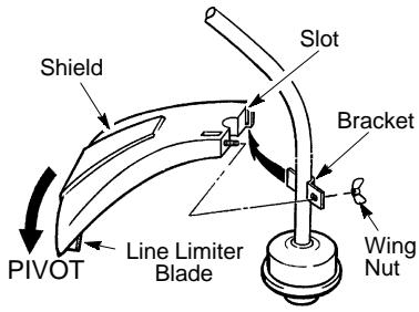
ATTACHING SHIELD
WARNING: The shield must be properly installed. The shield provides partial protection from the risk of thrown objects to the oper
SAFETY NOTICE: Exposure to vibrations through prolonged use of gasoline powered hand tools could cause blood vessel or nerve damage in the fingers, hands, and joints of people prone to circulation disorders or abnormal swellings. Prolonged use in cold weather has been linked to blood vessel damage in otherwise healthy people. If symptoms occur such as numbness, pain, loss of strength, change in skin color or texture, or loss of feeling in the fingers, hands, or joints, discontinue the use of this tool and seek medical attention. An anti-vibration system does not guarantee the avoidance of these problems. Users who operate power tools on a continual and regular basis must monitor closely their physical condition and the condition of this tool.
SPECIAL NOTICE: This unit is equipped with a temperature limiting muffler and spark arresting screen which meets the requirements of California Codes 4442 and 4443. All U.S. forest land and the states of California, Idaho, Maine, Minnesota, New Jersey, Oregon, and Washington require by law that many internal combustion engines be equipped with a spark arresting screen. If you operate in a locale where such regulations exist, you are legally responsible for maintaining the operating condition of these parts. Failure to do so is a violation of the law. For normal homeowner use, the muffler and spark arresting screen will not require any service. After 50 hours of use, we recommend that your muffler be serviced or replaced by your authorized service dealer.
tor and others and is equipped with a line limiter blade which cuts excess line to the proper length. The line limiter blade (on underside of shield) is sharp and can cut you.
For proper orientation of shield, see KNOW YOUR TRIMMER illustration in OPERATION section.
- Remove wing nut from shield.
- Insert bracket into slot as shown.
- Pivot shield until bolt passes through hole in bracket.
- Securely tighten wing nut onto bolt.
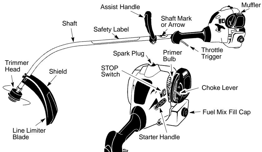
KNOW YOUR TRIMMER
READ THIS INSTRUCTION MANUAL AND SAFETY RULES BEFORE OPERATING YOUR UNIT. Compare the illustrations with your unit to familiarize yourself with the location of the various controls and adjustments. Save this manual for future reference.
STOP SWITCH
The STOP switch is used to stop the engine. To stop the engine, push and hold the switch in the STOP position until the engine stops.
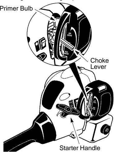
PRIMER BULB
The PRIMER BULB removes air from the carburetor and fuel lines and fills them with fuel. This allows you to start the engine with fewer pulls on the starter rope. Activate the primer bulb by pressing it and allowing it to return to its original form.
CHOKE
The CHOKE helps to supply fuel to the engine to aid in cold starting. Activate the choke by moving the choke lever to the FULL CHOKE position. After the engine attempts to start, move the choke lever to the HALF CHOKE position. Once engine has started, move the choke lever to the RUN position.
BEFORE STARTING ENGINE

WARNING: Be sure to read the fuel information in the safety rules before you begin. If you do not understand the safety rules, do not attempt to fuel your unit. Call 1-800-554-6723.
FUELING ENGINE

WARNING: Remove fuel cap slowly when refueling.

HELPFUL TIP
To obtain the correct oil mix ratio, pour 3.2 ounces of 2-cycle synthetic oil into one gallon of fresh gas.
This engine is certified to operate on unleaded gasoline. Before operation, gasoline must be mixed with a good quality synthetic 2-cycle air-cooled engine oil designed to be mixed at a ratio of 40:1. Poulan/Weed Eater brand synthetic oil is recommended. Mix gasoline and oil at a ratio of 40:1. A 40:1 ratio is obtained by
mixing 3.2 ounces (95 ml) of oil with 1 gallon (4 liters) of unleaded gasoline. DO NOT USE automotive oil or marine oil. These oils will cause engine damage. When mixing fuel, follow instructions printed on container. Once oil is added to gasoline, shake container momentarily to assure that the fuel is thoroughly mixed. Always read and follow the safety rules relating to fuel before fueling your unit.
IMPORTANT
Experience indicates that alcohol blended fuels (called gasohol or using ethanol or methanol) can attract moisture which leads to separation and formation of acids during storage. Acidic gas can damage the fuel system of an engine while in storage. To avoid engine problems, empty the fuel system before storage for 30 days or longer. Drain the gas tank, start the engine and let it run until the fuel lines and carburetor are empty. Use fresh fuel next season. Never use engine or carburetor cleaner products in the fuel tank or permanent damage may occur. See the STORAGE section for additional information.

HELPFUL TIP
If your engine switch reads "push to stop", it is always in the ON position.
HOW TO STOP YOUR UNIT
- To stop the engine, push and hold the STOP switch in the STOP position until the engine stops.
- If engine does not stop, move choke to the FULL CHOKE position.
HOW TO START YOUR UNIT
WARNING: The trimmer head will turn while starting the engine. Avoid any contact with the muffler. A hot muffler can cause serious burns.

HELPFUL TIP
If your engine still does not start after following these instructions, please call 1-800-554-6723.
STARTING A COLD ENGINE (or a warm engine after running out of fuel)
- Set unit on a flat surface.
- Slowly press the primer bulb 6 times.
- Move choke lever to the FULL CHOKE position.
- Squeeze the throttle trigger fully and hold through all remaining steps.
-
Pull starter rope handle sharply until engine sounds as if it is trying to start, but do not pull rope more than 6 times.
-
As soon as engine sounds as if it is trying to start, move choke lever to HALF CHOKE position.
-
Pull starter rope sharply until engine runs, but no more than 6 pulls.
NOTE: If the engine doesn't start after 6 pulls (at the HALF CHOKE position), move the choke lever to the FULL CHOKE position and press the primer bulb 6 times. Squeeze and hold the throttle trigger and pull the starter rope 2 more times. Move the choke lever to the HALF CHOKE position and pull the starter rope until the engine runs, but no more than 6 pulls. If the engine still doesn't start, it is probably flooded. Proceed to STARTING A FLOODED ENGINE.
- Once the engine starts, allow it to run 10 seconds, then move the choke lever to the RUN position. Allow the unit to run for 30 more seconds at RUN before releasing the throttle trigger.
NOTE: If engine dies with the choke lever in the RUN position, move the choke lever to the HALF CHOKE position and pull the rope until engine runs, but no more than 6 pulls.
STARTING A WARM ENGINE
- Move the choke lever to the HALF CHOKE position.
- Squeeze and hold the throttle trigger. Keep throttle trigger fully squeezed until the engine runs smoothly.
- Pull starter rope sharply until engine runs, but no more than 6 pulls.
- Allow engine to run 15 seconds, then move the choke lever to RUN.
NOTE: If engine has not started, pull starter rope 5 more pulls. If engine still does not run, it is probably flooded.
STARTING A FLOODED ENGINE
Flooded engines can be started by placing the choke lever in the RUN position; then, pull the rope to clear the engine of excess fuel. This could require pulling the starter handle many times depending on how badly the unit is flooded. If the unit still doesn't start, refer to TROUBLESHOOTING TABLE or call 1-800-554-6723.
OPERATING INSTRUCTIONS
It is recommended that the engine not be operated for longer than 1 minute at full throttle.
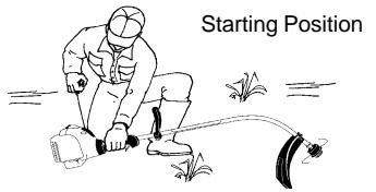
OPERATING POSITION

Cut from your right to your left.

WARNING: Always wear eye protec
tion. Never lean over the trimmer head. Rocks or debris can ricochet or be thrown into eyes and face and cause blindness or other serious injury.
Do not run the engine at a higher speed than necessary. The cutting line will cut efficiently when the engine is run at less than full throttle. At lower speeds, there is less engine noise and vibration. The cutting line will last longer and will be less likely to "weld" onto the spool.
Always release the throttle trigger and allow the engine to return to idle speed when not cutting.
To stop engine:
- Release the throttle trigger.
- Push and hold the STOP switch in the STOP position until the engine stops.
The trimmer line will advance approximately 2 inches (5 cm) each time the bottom of the trimmer head is tapped on the ground with the engine running at full throttle.
The most efficient line length is the maximum length allowed by the line limiter. Always keep the shield in place when the tool is being operated.
To advance line:
- Operate the engine at full throttle.
- Hold the trimmer head parallel to and above the grassy area.
- Tap the bottom of the trimmer head lightly on the ground one time. Approximately 2 inches (5 cm) of line will be advanced with each tap.
Always tap the trimmer head on a grassy area. Tapping on surfaces such as concrete or asphalt can cause excessive wear to the trimmer head.
If the line is worn down to 2 inches (5 cm) or less, more than one tap will be required to obtain the most efficient line length.
WARNING: Use only 0.080'' (2 mm) diameter line. Other sizes of line will not advance properly and will result in improper cutting head function or can cause serious injury. Do not use other materials such as wire, string, rope, etc. Wire can break off during cutting and become a dangerous missile that can cause serious injury.
CUTTING METHODS

WARNING: Use minimum speed do not crowd the line when cutting around objects (rock, gravel, fence posts, etc.), ch can damage the trimmer head, become angled in the line, or be thrown causing aous hazard.
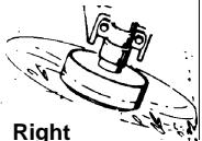
- The tip of the line does the cutting. You will achieve the best performance and minimum line wear by not crowding the line into the cutting area. The right and wrong ways are shown below.
Tip of the Line Does The Cutting
Line Crowded Into Work Area
- The line will easily remove grass and weeds from around walls, fences, trees and flower beds, but it also can cut the tender bark of trees or shrubs and scar fences. To help avoid damage especially to delicate vegetation or trees with tender bark, shorten line to 4-5 inches (10-13 cm) and use at less than full throttle.
- For trimming or scalping, use less than full throttle to increase line life and decrease head wear, especially:
During light duty cutting. - Near objects around which the line can wrap such as small posts, trees or fence wire.
- For mowing or sweeping, use full throttle for a good clean job.
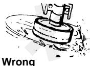
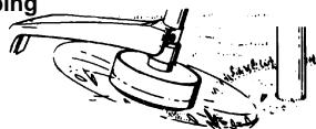
TRIMMING - Hold the bottom of the trimmer head about 3 inches (8 cm) above the ground and at an angle. Allow only the tip of the line to make contact. Do not force trimmer line into work area.
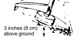
Trimming
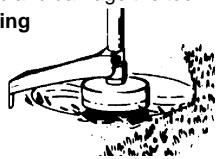
SCALPING - The scalping technique removes unwanted vegetationdown to the ground. Hold the bottom of the trimmer head about 3 inches (8 cm) above the ground and at an angle. Allow the tip of the line to strike the ground around trees, posts, monuments, etc. This technique increases line wear.
Scalping
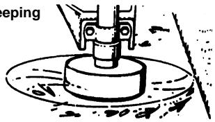
MOWING - Your trimmer is ideal for mowing in places conventional lawn mowers cannot reach. In the mowing position, keep the line parallel to the ground. Avoid pressing the head into the ground as this can scalp the ground and damage the tool.
Mowing
SWEEPING - The fanning action of the rotating line can be used for a quick and easy clean up. Keep the line parallel to and above the surfaces being swept and move the tool from side to side.
MAINTENANCE

WARNING: Disconnect the spark before performing maintenance except carburetor adjustments.

HELPFUL TIP
IMPORTANT: Have all repairs other than the recommended maintenance described in the instruction manual performed by an authorized service dealer.
If any dealer other than an authorized service dealer performs work on the product, Electrolux Home Products, Inc., may not pay for repairs under warranty. It is your responsibility to maintain and perform general maintenance.
CHECK FOR LOOSE
FASTENERS AND PARTS
- Spark Plug Boot
Air Filter - Housing Screws
- Assist Handle Screws
- Debris Shield
CHECK FOR DAMAGED OR WORN PARTS
Contact an authorized service dealer for replacement of damaged or worn parts.
- STOP Switch - Ensure STOP switch functions properly by pushing and holding the switch in the STOP position. Make sure engine stops. Restart engine and continue.
Fuel Tank - Discontinue use of unit if fuel tank shows signs of damage or leaks. - Debris Shield - Discontinue use of unit if debris shield is damaged.
INSPECT AND CLEAN UNIT AND LABELS
- After each use, inspect complete unit for loose or damaged parts. Clean the unit and labels using a damp cloth with a mild detergent.
- Wipe off unit with a clean dry cloth.
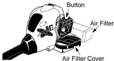
CLEAN AIR FILTER
A dirty air filter decreases engine performance and increases fuel consumption and harmful emissions. Always clean after every 5 hours of operation.
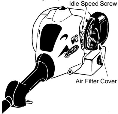
- Clean the air filter cover and the area around it to keep dirt from falling into the carburetor chamber when the cover is opened.
- Open air filter cover by pushing button (see illustration). Remove air filter.
NOTE: To avoid creating a fire hazard or producing harmful evaporative emissions, do not clean filter in gasoline or other flammable solvent.
- Wash the filter in soap and water.
- Allow filter to dry.
- Replace air filter and close cover.
MUFFLER AND SPARK ARRESTING SCREEN

WARNING: The muffler on this product contains chemicals known to the State of California to cause cancer.
As your unit is used, carbon deposits build up on the muffler and spark arresting screen. For normal homeowner use, however, the muffler and spark arresting screen will not require any service. After 50 hours of use, we recommend that your muffler be serviced or replaced by your authorized service dealer.
REPLACE SPARK PLUG
Replace the spark plug each year to ensure the engine starts easier and runs better. Set spark plug gap at 0.025 inch (0.6 mm). Ignition timing is fixed and nonadjustable.
- Twist, then pull off spark plug boot.
- Remove spark plug from cylinder and discard.
- Replace with Champion RCJ-6Y spark plug and tighten securely with a 3/4 inch (19 mm) socket wrench.
- Reinstall the spark plug boot.
SERVICE AND ADJUSTMENTS
LINE REPLACEMENT
- Remove spool by firmly pulling on tap button.
- Clean entire surface of hub and spool.
- Replace with a pre-wound spool, or cut two lengths of 12-1/2 feet of 0.080'' (2 mm) diameter Weed Eater® brand line.
WARNING: Never use wire, rope, string, etc., which can break off and become a dangerous missile.
4. Insert ends of the lines about 1/2 inch (1 cm) into the small holes on the inside of spool.
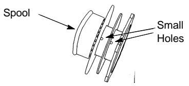
- Wind the line evenly and tightly onto the spool. Wind in the direction of the arrows found on the spool.
- Push the lines into the notches, leaving 3 to 5 inches (7 - 12 cm) unwound.
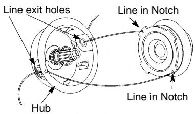
- Insert the lines into the the exit holes in the hub as shown in the illustration.
- Align the notches with the line exit holes.
- Push spool into hub until it snaps into place.
- Pull the lines extending outside of the hub to release the lines from the notches.
CARBURETOR ADJUSTMENT
WARNING: Keep others away when making idle speed adjustments. The trimmer head will be spinning during this procedure. Wear your protective equipment and observe all safety precautions.
The carburetor has been carefully set at the factory. Adjustments may be necessary if you notice any of the following conditions:
Engine will not idle when the throttle is released.
Make adjustments with the unit supported so the cutting attachment is off the ground and will not make contact with any object. Hold the unit by hand while running and making adjustments. Keep all parts of your body away from the cutting attachment and muffler.
Idle Speed Adjustment
Allow engine to idle. Adjust speed until engine runs without stalling (idle speed too slow).
- Turn idle speed screw clockwise to increase engine speed if engine stalls or dies.
- Turn idle speed screw counterclockwise to decrease engine speed.
If you require further assistance or are unsure about performing this procedure, contact an authorized service dealer or call 1-800-554-6723.
WARNING: Perform the following steps after each use:
- Allow engine to cool, and secure the unit before storing or transporting.
- Store unit and fuel in a well ventilated area where fuel vapors cannot reach sparks or open flames from water heaters, electric motors or switches, furnaces, etc.
- Store unit with all guards in place. Position unit so that any sharp object cannot accidentally cause injury.
- Store unit and fuel well out of the reach of children.
SEASONAL STORAGE
Prepare unit for storage at end of season or if it will not be used for 30 days or more.
If your unit is to be stored for a period of time:
- Clean the entire unit before lengthy storage.
- Store in a clean dry area.
- Lightly oil external metal surfaces.
FUEL SYSTEM
Under FUELING ENGINE in the OPERATION section of this manual, see message labeled IMPORTANT regarding the use of gasohol in your engine.
Fuel stabilizer is an acceptable alternative in minimizing the formation of fuel gum deposits during storage. Add stabilizer to the gasoline in the fuel tank or fuel storage container. Follow the mix instructions found on stabilizer container. Run engine at least 5 minutes after adding stabilizer.

HELPFUL TIP
During storage of your gas/ oil mixture, the oil will separate from the gas.
We recommend that you shake the gas can weekly to insure proper blending of the gas and oil.
ENGINE
- Remove spark plug and pour 1 teaspoon of 40:1, 2-cycle engine oil (air cooled) through the spark plug opening. Slowly pull the starter rope 8 to 10 times to distribute oil.
- Replace spark plug with new one of recommended type and heat range.
- Clean air filter.
- Check entire unit for loose screws, nuts, and bolts. Replace any damaged, broken, or worn parts.
- At the beginning of the next season, use only fresh fuel having the proper gasoline to oil ratio.
OTHER
- Do not store gasoline from one season to another.
- Replace your gasoline can if it starts to rust.
| TROUBLE | CAUSE | REMEDY |
| Engine will not start. | 1. Engine flooded.2. Fuel tank empty.3. Spark plug not firing.4. Fuel not reaching carburetor.5. Carburetor requires adjustment. | 1. See "Starting a Flooded Engine in Operation Section.2. Fill tank with correct fuel mixture.3. Install new spark plug.4. Check for dirty fuel filter; replace. Check for kinked or split fuel line; repair or replace.5. Contact an authorized service dealer. |
| Engine will not idle properly. | 1. Carburetor requires adjustment.2. Crankshaft seals worn.3. Compression low. | 1. See "Carburetor Adjustment" in Service and Adjustments Section.2. Contact an authorized service dealer.3. Contact an authorized service dealer. |
| Engine will not accelerate, lacks power, or dies under a load. | 1. Air filter dirty.2. Spark plug fouled.3. Carburetor requires adjustment.4. Carbon build-up on muffler outlet screen.5. Compression low. | 1. Clean or replace air filter.2. Clean or replace plug and regap.3. Contact an authorized service dealer.4. Contact an authorized service dealer.5. Contact an authorized service dealer. |
| Engine smokes excessively. | 1. Choke partially on.2. Fuel mixture incorrect.3. Air filter dirty.4. Carburetor requires adjustment. | 1. Adjust choke.2. Empty fuel tank and refill with correct fuel mixture.3. Clean or replace air filter.4. Contact an authorized service dealer. |
| Engine runs hot. | 1. Fuel mixture incorrect.2. Spark plug incorrect.3. Carburetor requires adjustment.4. Carbon build-up on muffler outlet screen. | 1. See "Fueling Engine" in Operation section.2. Replace with correct spark plug.3. Contact an authorized service dealer.4. Contact an authorized service dealer. |
LIMITED WARRANTY
ELECTROLUX HOME PRODUCTS, INC., warrants to the original purchaser that each new Weed Eater® brand gasoline tool or attachment is free from defects in material and workmanship and agrees to repair or replace under this warranty any defective gasoline product or attachment as follows from the original date of purchase.
2 YEARS - Parts and Labor, when used for household purposes.
60 DAYS - Parts and Labor, when used for commercial, professional, or income producing purposes.
30 DAYS - Parts and Labor, if used for rental purposes.
This warranty is not transferable and does not cover damage or liability caused by improper handling, improper maintenance, or the use of accessories and/or attachments not specifically recommended by ELECTROLUX HOME PRODUCTS, INC., for this tool. Additionally, this warranty does not cover tune-ups, spark plugs, filters, starter ropes, starter springs, cutting line, or rotating head parts that will wear and require replacement with reasonable use during the warranty period. This warranty does not cover predelivery setup or normal adjustments explained in the instruction manual.
THIS WARRANTY GIVES YOU SPECIFIC LEGAL RIGHTS, AND YOU MAY HAVE OTHER RIGHTS WHICH VARY FROM STATE TO STATE.
NO CLAIMS FOR CONSEQUENTIAL OR OTHER DAMAGES WILL BE ALLOWED, AND THERE ARE NO OTHER EXPRESS WARRANTY EXCEPTION EXCEPT THOSE EXPRESSLY STIPULATED HEREIN.
SOME STATES DO NOT ALLOW LIMITATIONS ON HOW LONG AN IMPLIED WARRANTY LASTS OR THE EXCLUSION OR LIMITATIONS OF INCIDENTAL OR CONSEQUENTIAL DAMAGES, SO THE ABOVE LIMITATIONS OR EXCLUSION MAY NOT APPLY TO YOU.
The policy of ELECTROLUX HOME PRODUCTS, INC., is to continuously improve its products. Therefore, ELECTROLUX HOME PRODUCTS, INC., reserves the right to change, modify, or discontinue models, designs, specifications, and accessories of all products at any time without notice or obligation to any purchaser.
U.S. EPA/ CALIFORNIA/ENVIRONMENT CANADA EMISSION CONTROL WARRANTY STATEMENT
YOUR WARRANTY RIGHTS AND OBLIGATIONS: The U.S. Environmental Protection Agency, California Air Resources Board, Environment Canada and ELECTROLUX HOME PRODUCTS, INC., are pleased to explain the emissions control system warranty on your year 2002-2004 small off-road engine. In California, all small off-road engines must be designed, built, and equipped to meet the State's stringent anti-smog standards. ELECTROLUX HOME PRODUCTS, INC., must warrant the emission control system on your small off-road engine for the periods of time listed below provided there has been no abuse, neglect, or improper maintenance of your small off-road engine. Your emission control system includes parts such as the carburetor and the ignition system. Where a warrantable condition exists, ELECTROLUX HOME PRODUCTS, INC., will repair your small off-road engine engine at no cost to you. Expenses covered under warranty include diagnosis, parts and labor. MANUFACTURER'S WARRANTY COVERAGE: If any emissions related part on your engine (as listed under Emissions Control Warranty Parts List) is defective or a defect in the materials or workmanship of the engine causes the failure of such an emission related part, the part will be repaired or replaced by ELECTROLUX HOME PRODUCTS, INC. OWNER'S WARRANTY RESPONSIBILITIES: As the small off-road engine engine owner, you are responsible for the performance of the required maintenance listed
in your instruction manual. ELECTROLUX HOME PRODUCTS, INC., recommends that you retain all receipts covering maintenance on your small off-road engine, but ELECTROLUX HOME PRODUCTS, INC., cannot deny warranty solely for the lack of receipts or for your failure to ensure the performance of all scheduled maintenance. As the small off-road engine engine owner, you should be aware that ELECTROLUX HOME PRODUCTS, INC., may deny you warranty coverage if your small off-road engine or a part of it has failed due to abuse, neglect, improper maintenance, unapproved modifications, or the use of parts not made or approved by the original equipment manufacturer. You are responsible for presenting your small off-road engine to an ELECTROLUX HOME PRODUCTS, INC., authorized repair center as soon as a problem exists. Warranty repairs should be completed in a reasonable amount of time, not to exceed 30 days. If you have any questions regarding your warranty rights and responsibilities, you should contact your nearest authorized service center or call ELECTROLUX HOME PRODUCTS, INC., at 1-800-554-6723. WARRANTY COMMENCEMENT DATE: The warranty period begins on the date the small off-road engine is purchased. LENGTH OF COVERAGE: This warranty shall be for a period of two years from the initial date of purchase. WHAT IS COVERED: REPAIR OR REPLACEMENT OF PARTS. Repair or replacement of any war
ranted part will be performed at no charge to the owner at an approved ELECTROLUX HOME PRODUCTS, INC., servicing center. If you have any questions regarding your warranty rights and responsibilities, you should contact your nearest authorized service center or call ELECTROLUX HOME PRODUCTS, INC., at 1-800-554-6723. WARRANTY PERIOD: Any warranted part which is not scheduled for replacement as required maintenance, or which is scheduled only for regular inspection to the effect of "repair or replace as necessary" shall be warranted for 2 years. Any warranted part which is scheduled for replacement as required maintenance shall be warranted for the period of time up to the first scheduled replacement point for that part. DIAGNOSIS: The owner shall not be charged for diagnostic labor which leads to the determination that a warranted part is defective if the diagnostic work is performed at an approved ELECTROLUX HOME PRODUCTS, INC., servicing center. CONSEQUENTIAL DAMAGES: ELECTROLUX HOME PRODUCTS, INC., may be liable for damages to other engine components caused by the failure of a warranted part still under warranty. WHAT IS NOT COVERED: All failures caused by abuse, neglect, or improper maintenance are not covered. ADD-ON OR MODIFIED PARTS: The
use of add-on or modified parts can be grounds for disallowing a warranty claim. ELECTROLUX HOME PRODUCTS, INC., is not liable to cover failures of warranted parts caused by the use of add-on or modified parts. HOW TO FILE A CLAIM: If you have any questions regarding your warranty rights and responsibilities, you should contact your nearest authorized service center or call ELECTROLUX HOME PRODUCTS, INC., at 1-800-554-6723. WHERE TO GET WARRANTY SERVICE: Warranty services or repairs shall be provided at all ELECTROLUX HOME PRODUCTS, INC., service centers. Call: 1-800-554-6723. MAINTENANCE, REPLACEMENT AND REPAIR OF EMISSION RELATED PARTS: Any ELECTROLUX HOME PRODUCTS, INC., approved replacement part used in the performance of any warranty maintenance or repair on emission related parts will be provided without charge to the owner if the part is under warranty. EMISSION CONTROL WARRANTY PARTS LIST: Carburetor, Ignition System: Spark Plug (covered up to maintenance schedule), Ignition Module, Muffler including catalyst. MAINTENANCE STATEMENT: The owner is responsible for the performance of all required maintenance as defined in the instruction manual.
The information on the product label indicates to which standard your engine is certified. Example: (Year) EPA Phase I or Phase II and/or CALIFORNIA.
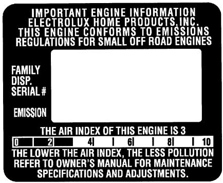
This engine is certified to be emissions compliant for the following use:
Moderate (50 hours)
Intermediate (125 hours)
Extended (300 hours)