
WEEL15TNE - Brush cutter WEED EATER - Free user manual and instructions
Find the device manual for free WEEL15TNE WEED EATER in PDF.
| Product type | Brush cutter |
| Brand | WEED EATER |
| Model | WEEL15TNE |
| Power source | 2-stroke petrol engine |
| Displacement | 30 cm³ |
| Power | 1.5 hp |
| Fuel tank capacity | 0.5 L |
| Weight | 6 kg |
| Cutting width | 45 cm |
| Head type | Line and blade interchangeable head |
| Rotation speed | 8000 rpm |
| Ignition system | Electronic |
| Starting | Recoil starter |
| Carburetor | Diaphragm |
| Safety | Blade guard, emergency stop |
| Maintenance | Clean after each use, lubricate gears |
| Spare parts available | Spark plug, air filter, blade, trimmer line |
Frequently Asked Questions - WEEL15TNE WEED EATER
User questions about WEEL15TNE WEED EATER
0 question about this device. Answer the ones you know or ask your own.
Ask a new question about this device
Download the instructions for your Brush cutter in PDF format for free! Find your manual WEEL15TNE - WEED EATER and take your electronic device back in hand. On this page are published all the documents necessary for the use of your device. WEEL15TNE by WEED EATER.
USER MANUAL WEEL15TNE WEED EATER
Please do not return unit to retailer.
Register your product online at:
Registresubproductonelinedan:
Read and follow all Safety Rules and Operating Instructions before using this product. Read instructions carefully before assembling. Failure to do so can result in serious injury.
ADVERTENCIA:
7349 Statesville Road
Charlotte, NC 28269
WEED EATER
850 Matheson Blvd. West
Mississauga, Ontario L5V 0B4
WARNING: When using electric gardening appliances, basic safety precautions must always be followed to reduce the risk of fire, electric shock, and serious injury. Read and follow all instructions.
SAFETY INFORMATION ON THE UNIT
This power unit can be dangerous! Operator is responsible for following the warnings and instructions in this manual and on the unit. Read entire instruction manual before using unit! Be thoroughly familiar with the controls and the proper use of the unit. Restrict the use of this unit to persons who read, understand, and follow unit and manual warnings and instructions. Never allow children to operate this unit. Close attention is necessary when used near children.
DANGER: Never use blades or flailing devices. Unit is designed for line trimmer use only. Use of any other accessories or attachments will increase the risk of injury.


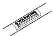
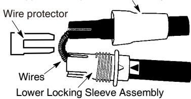
WARNING: Trimmer line throws objects violently. You and others can be blinded/ injured. Wear safety glasses, boots, and leg protection. Keep body parts clear of rotating line.
Safety Glasses or similar eye protection
Keep children, bystanders, and animals 50 feet (15 meters) away. If approached stop unit immediately.
If situations occur which are not covered in this manual, use care and good judgement. If you need assistance, call 1-800-554-6723.
OPERATOR SAFETY
- Dress properly. Always wear safety glasses or similar eye protection when operating, or performing maintenance on your unit. (Safety glasses are available.) Always wear face or dust mask if operation is dusty. Always wear heavy, long pants, long sleeves, boots, and gloves. Do not go barefoot or wear sandals.
-
Secure hair above shoulder length. Secure or remove loose clothing and jewelry or clothing with loosely hanging ties, straps, tassels, etc. They can be caught in moving parts.
-
Being fully covered also helps protect you from debris and pieces of toxic plants thrown by spinning line.
- Stay Alert. Do not operate unit when you are tired, ill, upset or under influence of alcohol, drugs, or medication. Watch what you are doing; use common sense.
- Avoid unintentional starting of the unit. Never carry unit with your finger on the switch. Be sure the switch is in the OFF position and never touch the switch when connecting extension cord.
ELECTRICAL SAFETY
WARNING: Avoid a dangerous environment. To reduce the risk of electrical shock, do not use in rain, in damp or wet locations, or around swimming pools, hot tubs, etc. Do not expose to snow, rain, or water to avoid the possibility of electrical shock.
- Use a voltage supply as shown on unit.
- Avoid dangerous situations. Do not use in the presence of flammable liquids or gases to avoid creating a fire or explosion and/or causing damage to unit.
- To reduce the risk of electrical shock, this equipment has a polarized plug (one blade is wider than the other) and will require the use of a polarized extension cord. The appliance plug will fit into a polarized extension cord only one way. If the plug does not fit fully into the extension cord, reverse the plug. If the plug still does not fit, obtain a correct polarized extension cord. A polarized extension cord will require the use of a polarized wall outlet. This plug will fit into the polarized wall outlet only one way. If plug does not fit fully into the wall outlet, reverse the plug. If it still does not fit, contact a qualified electrician to install the proper wall outlet. Do not change the equipment plug, extension cord receptacle, or extension cord plug in any way.
- To reduce risk of electrical shock, use extension cords specifically marked as suitable for outdoor appliances having electrical rating not less than the rating of unit. Cord must be marked with suffix "W-A" (in Canada "W"). Make sure your extension cord is in good condition. Inspect extension cord before use and replace if damaged.
Do not use a damaged cord. Cord insulation must be intact with no cracks or deterioration. Plug connectors must be undamaged. An undersized extension cord will cause adrop in line voltage resulting in loss of power and overheating. If in doubt, use the next heavier gauge. The lower the gauge number, the heavier the cord (see SELECT ANEXTENSION CORD in the OPERATION section).
-
Do not use multiple cords.
-
Do not abuse cord. Never carry the unit by the extension cord or yank extension cord to disconnect unit.
- Use cord retainer to prevent disconnection of extension cord from unit and possible damage to the unit due to plug movement (see ATTACH THE EXTENSION CORD TO YOUR TRIMMER in the OPERATION section).
- Do not use the unit if the switch does not turn the unit on and off properly. Repairs to the switch must be made by your authorized service dealer.
- Keep the extension cord clear of operator and obstacles at all times. Do not expose cords to heat, oil, water, or sharp edges.
- To avoid the possibility of electric shock, avoid body contact with any grounded conductor, such as metal fences or pipes.
- Ground Fault Circuit Interruption (GFCI) protection should be provided on circuit or outlet to be used. Receptacles are available having built-in GFCI protection and may be used for this measure of safety.
UNIT SAFETY
- Inspect unit before use. Replace damaged parts. Make sure all handles, guards, and fasteners are in place and securely fastened. Parts that are damaged must be repaired or replaced by an authorized service dealer. These include head parts that are cracked, or chipped, guards, and any other part that is damaged.
- Do not repair unit yourself.
- Use only 0.065 inch (1.65 mm) diameter recommended trimmer line (see USER REPLACEABLE SERVICE PARTS in the SERVICE AND ADJUSTMENTS section). Never use wire, rope, string, etc.
- Use specified trimmer spool. Make sure spool is properly installed and all parts are securely fastened.
- Use only WEED EATER replacement parts and accessories as recommended.
CUTTING SAFETY
- Inspect area to be cut. Remove objects (rocks, broken glass, nails, wire, string, etc.) which can be thrown or become entangled in cutting head.
- Do not overreach or stand on unstable support. Keep firm footing and balance.
- Keep the cutting head below waist level. Do not raise handles above your waist. Cutting head can come dangerously close to your body.
- Keep away from cutting head and spinning line.
- Use unit properly. Use only for trimming, edging, scaling, and mowing. Do not force unit. It will do the job better and with less risk of injury at the rate for which it was designed.
- Use only in daylight or in good artificial light.
MAINTENANCE SAFETY
WARNING: Disconnect unit from the power supply before performing maintenance, or when changing trimmer line.
- Maintain unit according to recommended procedures. Keep cutting line at proper length. Follow instructions for changing trimmer line.
- Have all service and maintenance not explained in this manual performed by an authorized service dealer to avoid creating a hazard.
- Never douse or squirt the unit with water or any other liquid. Clean unit and decals with a damp sponge. Keep handles dry, clean, and free from oil and grease.
- Keep the air vents clean and free of debris to avoid overheating the motor. Clean after each use.
TRANSPORTING AND STORAGE
- Stop the unit and disconnect the power source when not in use.
- Carry the unit with motor stopped.
- Store the unit so the line limiter blade (on underside of shield) cannot cause injury.
- Store unit indoors in a high, dry place out of the reach of children. Store unit unplugged.
- Do not hang unit so that the trigger switch is depressed.
DOUBLE INSULATION CONSTRUCTION
This unit is double insulated to help protect against electric shock. Double insulation construction consists of two separate "layers" of electrical insulation instead of grounding.
Tools built with this insulation system are not intended to be grounded. No grounding means is provided on this unit, nor should a means of grounding be added to this unit. As a result, the extension cord used with your unit can be plugged into any standard 120 volt electrical outlet.
Safety precautions must be observed when operating any electrical tool. The double insulation system only provides added protection against injury resulting from an internal electrical insulation failure.
WARNING: All electrical repairs to this unit, including housing, switch, motor, locking sleeve assembly, wires, etc., must be diagnosed and repaired by qualified service personnel. Replacement parts for a double insulated appliance must be recommended by the manufacturer. A double insulated appliance is marked with the words "double insulation" or "double insulated". The symbol (square within a square) may also be marked on the appliance. Failure to have the unit repaired by qualified service personnel can cause the double insulation construction to become ineffective and result in serious injury.
SAVE THESE INSTRUCTIONS
ASSEMBLY
WARNING: If received assembled, review all assembly steps to ensure your unit is properly assembled and all fasteners are secure.
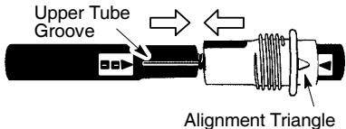
TUBE ASSEMBLY
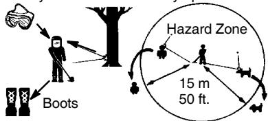
Upper Locking Sleeve Assembly
- Remove the wire protector from the tubes and discard.
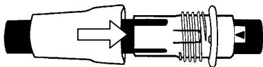
- Align upper tube groove with triangle on lower locking sleeve assembly. Push tubes together until they snap into place.
- Try to pull tubes back apart. If the tubes do not come apart, they are properly snapped into place. If the tubes come apart, repeat step 1 and push until the tubes snap into place.
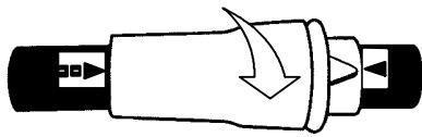
- Slide upper locking sleeve assembly over lower locking sleeve assembly and tighten by turning clockwise.
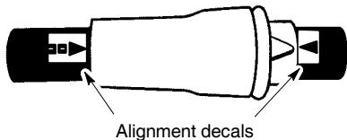
- Ensure locking sleeve assembly and alignment decals appear as illustrated below.
WARNING: Failure to completely enclose excess wires in upper tube during assembly of the unit may result in damage to the wires and/or the unit or serious injury to the operator including electrocution.
WARNING: The upper and lower tubes must be snapped together, remain permanently assembled together and the locking sleeve assembly must be fully tightened before and during use to avoid serious injury to the operator and/or damage to the unit. DO NOT attempt to disassemble unit after initial assembly.
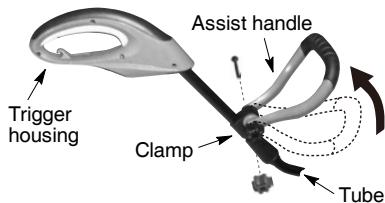
INSTALLATION OF ASSIST HANDLE
- Place unit on a flat surface.
- Remove knob and bolt from kit.
- Push assist handle over the clamp on the tube (see illustration). Handle can be assembled as option 1 or 2 (Shown Below) depending on the users preference.
- Install bolt in handle. Thread knob onto bolt.
- Adjust the handle up and down the tube and pivot it to a comfortable position; tighten knob securely.
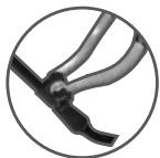
Option 1
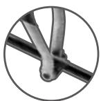
Option 2
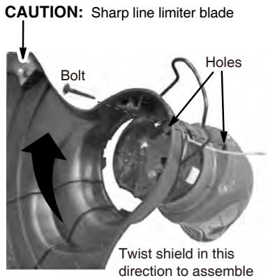
ATTACHING EDGE GUIDE AND SHIELD
WARNING: The shield must be properly installed. The shield provides partial protection from the risk of thrown objects to the operator and others. Your unit is equipped with a line limiter blade, which cuts excess line to the proper length while running. The line limiter blade (on underside of shield) is sharp and can cut you.
NOTE: If shield is not properly installed, damage to unit (including motor failure) will result.
- Insert edge guide into two holes in shield.
NOTE: Edge guide must be positioned on shield prior to installation on motor housing (see following illustration).

- Insert the shield onto the motor housing. Ensure the cutting head remains free to rotate and the line is not caught between the shield and the motor housing (see following illustration).
- Twist the shield as illustrated until the hole in the shield aligns with the hole in the housings. Make sure the shield is assembled to the unit as shown in the following illustration and in the KNOW YOUR UNIT section of this manual.
- Install bolt into shield and motor housing as shown. Tighten securely.
OPERATION
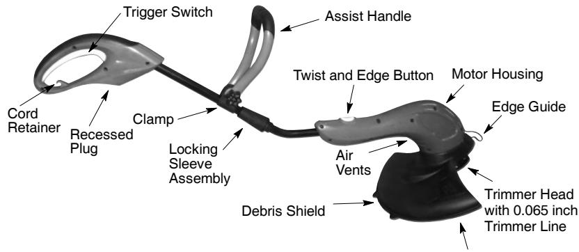
KNOW YOUR TRIMMER
READ THIS INSTRUCTION MANUAL AND SAFETY RULES BEFORE OPERATING YOUR UNIT. Compare the illustrations with your unit to familiarize yourself with the location of the various controls and adjustments. Save this manual for future reference.
Line Limiter Blade
RECESSED PLUG
The RECESSION PLUG is where you attach your extension cord to the unit.
TRIGGER SWITCH
The TRIGGER SWITCH is used to turn on the unit. Squeeze the trigger switch to operate the unit. Release to stop.
LINE LIMITER BLADE
The LINE LIMITER BLADE cuts the cutting line to the proper cutting length.
ASSIST HANDLE
The ASSIST HANDLE is used to help hold and guide the unit.
TRIMMER HEAD
The TRIMMER HEAD holds the cutting line and rotates during operation.
TWIST AND EDGE BUTTON
The TWIST AND EDGE BUTTON is used to twist the lower portion of the unit into an edging position.
EDGEGUIDE
The EDGE GUIDE protects the unit from contacting the ground during edging.
OPERATING INSTRUCTIONS
Use only a voltage supply as specified on your unit.
SELECT AN EXTENSION CORD
| Extension Cord Gauge Chart | |
| Length of Cord | Gauge |
| 25 Ft. (7.5 m) | 18 Gauge |
| 50 Ft. (15 m) | 16 Gauge |
| 100 Ft. (30 m) | 16 Gauge |
Extension cords are available for this unit.
ATTACH THE EXTENSION CORD TO YOUR TRIMMER
Loop your extension cord through the handle and around the hook as shown. Insure the plug and cord are firmly and fully engaged.
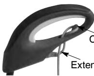
Cord Retainer
Extension Cord
CORRECT OPERATING POSITION
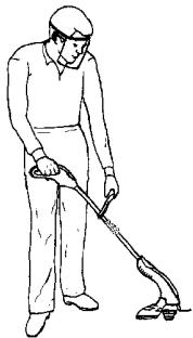
Trimming
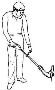
Edging
WARNING: Always wear eye protection. Never lean over the trimmer head. Rocks or debris can ricochet or be thrown into eyes and face and cause blindness or other serious injury.
When operating unit, stand as shown and check for the following:
- Wear eye protection and heavy clothing.
- Hold trigger handle with right hand and assist handle with left hand.
- Keep unit below waist level.
- Cut only from your right to your left to ensure debris is thrown away from you. Without bending over, keep line near and parallel to the ground (perpendicular when edging) and not crowded into material being cut.
The height of the trimmer can be adjusted to achieve the most comfortable operating position.
- Push the Twist 'N Edge Button.
- Adjust the trimmer to the desired height by moving the motor housing up or down the tube (four height positions available).
- Release the button. The tube will lock in position.
AUTOMATIC LINE FEED SYSTEM
When the trimmer is initially started, a small length of cutting line is fed out.
After approximately 5 seconds, the line will be cut to the correct length by the line limiter as the motor reaches full speed.
Make sure the motor is up to full speed before trimming.
If the noise of the cutting line being cut cannot be heard, more line will need to be fed out.
To feed more line:
- Allow the motor to stop completely; then, restart the motor and allow it to reach full speed.
- Repeat until you hear the line hitting against the line limiter (do not repeat this procedure more than 6 times).
If problems are experienced with the automatic line feed, refer to the TROUBLESHOOTING TABLE.
To manually feed the nylon line:
- If required, the cutting line can be fed out manually.
To operate, press and release manual line feed button while gently pulling on the line until the line reaches the line limiter.
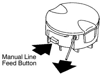
- If the line extends past the line limiter, too much line has been fed out. If too much line is fed out, remove the spool cap and click spool counterclockwise until the line is at the desired length.
WARNING: Use only 0.065 inch (1.65 mm) diameter round line. Other sizes and shapes of line will not advance properly and will result in improper cutting head function or can cause serious injury. Do not use other materials such as wire, string, rope, etc. Wire can break off during cutting and become a dangerous missile that can cause serious injury. See page 2 for warning concerning other cutting devices.
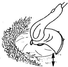
TRIMMING
Hold the bottom of the trimmer head about 3 inches (8 cm) above the ground and at an angle. Allow only the tip of the line to make contact. Do not force trimmer line into work area.
Trimming
3 inches (8 cm) above ground
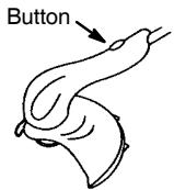
EDGING POSITION
While holding the trimmer in operating position, you can press this button and twist the lower portion 180^ counterclockwise for edging.
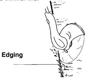
EDGING
While edging allow the tip of the line to make contact. Do not force the line. The edge guard helps protect the unit and keeps the unit from contacting the ground. Take extra caution while edging as objects can be thrown from the trimmer line.
SCALPING
The scalping technique removes unwanted vegetation. Hold the bottom of the trimmer head about 3 inches (8 cm) above the ground and at an angle. Allow the tip of the line to strike the ground around trees, posts, monuments, etc. This technique increases line wear.
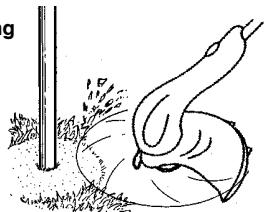
Scalping
MOWING
Your trimmer is ideal for mowing in places conventional lawn mowers cannot reach. In the mowing position, keep the line parallel to the ground. Avoid pressing the head into the ground as this can scalp the ground and damage the tool.
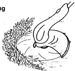
Mowing
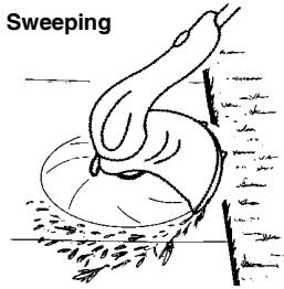
SWEEPING
The fanning action of the rotating line can be used for a quick and easy clean up. Keep the line parallel to and above the surfaces being swept and move the tool from side to side.
MAINTENANCE
WARNING: Disconnect power source before performing maintenance.
GENERAL RECOMMENDATIONS
The warranty on this unit does not cover items that have been subjected to operator abuse or negligence. To receive full value from the warranty, the operator must maintain unit as instructed in this manual. Various adjustments will need to be made periodically to properly maintain your unit.
BEFORE EACH USE
CHECK FOR LOOSE
FASTENERS AND PARTS
Housing Screws
- Locking Sleeve Assembly
- Assist Handle
- Debris Shield
- Edge Guide
CHECK FOR DAMAGED OR WORN PARTS
Contact an authorized service dealer for replacement of damaged or worn parts.
- Trigger Switch - Ensure switch functions properly by pressing and releasing the trigger switch. Make sure motor stops.
- Debris Shield - Discontinue use of unit if debris shield is damaged.
AFTER EACH USE
INSPECT AND CLEAN UNIT AND DECALS
- After each use, inspect complete unit for loose or damaged parts. Clean the unit using a damp cloth with a mild detergent.
- Wipe off unit with a clean dry cloth.
SERVICE AND ADJUSTMENTS
REPLACING THE LINE
- Disconnect the unit from the power source.
- Press and hold in the two cap release latches.
- Pull cap away from the hub.
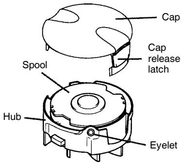
- Remove old spool.
- Clean entire surface of hub and spool.
- Replace with a pre-wound spool or cut a length of 26 feet (8 meters) of 0.065'' (1.65 mm) diameter WEED EATER brand line. Use of heavier lines could overload and damage unit.
WARNING: Never use wire, rope, string, etc., which can break off and become a dangerous missile.
- Insert end of line about 1/2 inch (1 cm) into small hole on the inside of the spool.
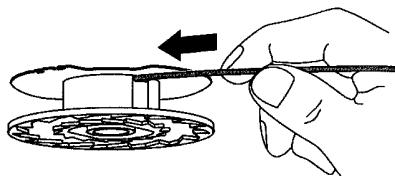
- Wind the line evenly and tightly onto the spool. Wind in the direction of the arrow found on the spool.
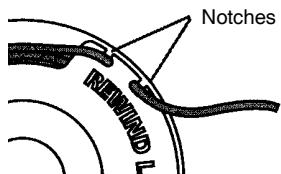
- Push the line into the notch, leaving 3 to 5 inches (7 - 12 cm) unwound.
- Place spool into hub with cut out area of spool in line with eyelet (see illustration).
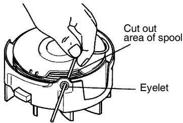
- Remove line from notch and feed line through eyelet.
- Reinstall the spool cap.
USER REPLACEABLE SERVICE PARTS
| REPLACEMENT PART | PART NUMBER |
| Spool with 0.065 inch Trimmer Line | 952711920 |
| Assist Handle | 574495601 |
| Bolt Carriage, M6 X 1 | 574495901 |
| Knob | 574473101 |
| Clamp | 574495801 |
| Shield Assembly | 574495401 |
| Edge Guide | 574491601 |
| Spool cap | 574492201 |
| Bolt | 574471601 |
STORAGE

WARNING: Perform the following
steps after each use.
- Stop the unit and disconnect the power source when not in use.
- Carry the unit with motor stopped.
-
Store the unit so the line limiter blade cannot cause injury.
-
Store unit and extension cord indoors in a high, dry place out of the reach of children. Store unit unplugged.
- Store unit with all guards in place. Position unit so that any sharp object cannot accidentally cause injury.
TROUBLESHOOTING TABLE

WARNING: Always stop unit and disconnect from the power source before performing all of the recommended remedies below except remedies that require unit to be operating.
| TROUBLE | CAUSE | REMEDY |
| Trimmer head stops under a load or does not turn when switch is pressed. | 1. Crowding trimmer line against material being cut. 2. Electrical failure. 3. Thrown circuit breaker. 4. Debris stopping head. | 1. Allow tip of line to do the cutting. 2. Contact your authorized service dealer. 3. Check breaker box. 4. Remove debris. |
| Line does not advance or breaks while cutting. | 1. Line improperly routed in head. 2. Line improperly wound into spool. 3. Incorrect line size 4. Not enough line outside of head. 5. Dirt buildup on unit. | 1. Check line routing. 2. Rewind line tightly and evenly. 3. Use only 0.065 inch (1.65 mm) dia. line. 4. Remove spool cap and pull 4 inches (10 cm) of line out of head. 5. Clean unit. |
| Line welds onto spool. | 1. Line size is incorrect. 2. Incorrect spool. 3. Line is being crowded against material being cut. | 1. Use only 0.065 inch (1.65 mm) dia. line. 2. Replace with correct spool. 3. Cut with tip of line fully extended. |
| Line releases continuously. | 1. Line improperly routed in head. 2. Spool damaged. | 1. Check line routing. 2. Replace spool. |
| Line usage is excessive. | 1. Line improperly routed in head. 2. Line size is incorrect. 3. Crowding line against material being cut. 4. Spool worn or damaged. | 1. Check line routing. 2. Replace spool. 3. Cut with tip of line fully extended. 4. Replace spool. |
| Line pulls back into head. | 1. Too little line outside of head. 2. Line size incorrect. | 1. Remove spool cap and pull 4 inches (10 cm) of line outside of head. 2. Use only 0.065 inch (1.65 mm) dia. line. |
LIMITED WARRANTY
WEEDEATER, a division of Husqvarna Consumer Outdoor Products N.A., Inc., warrants to the original consumer purchaser that each new WEED EATER brand electric or cordless product is free from defects in material and workmanship and agrees to repair or replace under this warranty any defective WEED EATER brand electric or cordless product within two (2) years from the original date of purchase.
If your WEED EATER brand electric or cordless product should fail within the limited warranty period, you may return it in complete condition, prepaid, with proof of purchase, to the dealer from whom it was purchased for repair or replacement at the option of WEED EATER.
This warranty is not transferable and does not cover damage or liability caused by improper handling, improper maintenance or alteration, or the use of accessories and/or attachments not specifically recommended by WEED EATER for this product. Additionally, this warranty does not cover parts that will wear and require replacement with reasonable use during the warranty period. This warranty does not cover predelivery set-up or normal adjustments explained in the instruction manual.
Should you have any unanswered questions concerning this warranty, please contact:
WEED EATER, a division of Husqvarna
Consumer Outdoor Products N.A., Inc.
7349 Statesville Road
Charlotte, NC 28269
1-800-554-6723
In Canada, contact:
WEEDEATER
850 Matheson Blvd. West
Mississauga, Ontario L5V 0B4
Giving the model number, serial number and date of purchase of your product and the name and address of the authorized dealer from whom it was purchased.
THIS WARRANTY GIVES YOU SPECIFIC LEGAL RIGHTS, AND YOU MAY HAVE OTHER RIGHTS WHICH VARY FROM STATE TO STATE.
NO CLAIMS FOR CONSEQUENTIAL OR OTHER DAMAGES WILL BE ALLOWED, AND THERE ARE NO OTHER EXPRESS WARRANTY EXCEPTIONS EXCEPT THOSE EXPRESSLY STIPULATED HEREIN.
SOME STATES DO NOT ALLOW LIMITATIONS ON HOW LONG AN IMPLIED WARRANTY LASTS OR THE EXCLUSION OR LIMITATIONS OF INCIDENTAL OR CONSEQUENTIAL DAMAGES, SO THE ABOVE LIMITATIONS OR EXCLUSION MAY NOT APPLY TO YOU.
This is a limited warranty within the meaning of that term as defined in the Magnuson-Moss Act of 1975.
The policy of WEED EATER is to continuously improve its products. Therefore, WEED EATER reserves the right to change, modify, or discontinue models, designs, specifications, and accessories of all products at any time without notice or obligation to any purchaser.