
HBR555T - Weather Station IROX - Free user manual and instructions
Find the device manual for free HBR555T IROX in PDF.



User questions about HBR555T IROX
0 question about this device. Answer the ones you know or ask your own.
Ask a new question about this device
Download the instructions for your Weather Station in PDF format for free! Find your manual HBR555T - IROX and take your electronic device back in hand. On this page are published all the documents necessary for the use of your device. HBR555T by IROX.
USER MANUAL HBR555T IROX
WETTERSTATION MIT WETTERRVORHERSAGE INNEN/AUSSEN FUNK- THERMO/HYGROMETER UND FUNKUHR (SWISS SIGNAL "HBG")
HBR555t
BEDIENUNGSANLEITUNG
IROX TE555X & TS33C MANUAL (GRE) SIZE: W65 X H105 (mm)
BY EMILY TSOI 14/12/06 FILM 19/12/06
1. EINFUHRUNG
E AUFWÄRTS [▲] TASTE
INDICATIONS D'ENTRETIEN
IROX TE555X & TS33C MANUAL (ITA)
SIZE: W65 X H105 (mm)
BY EMILY TSOI 14/12/06 FILM 19/12/06
1. INTRODUZIONE
SIZE: W65 X H105 (mm)
BY EMILY TSOI 14/12/06 FILM 19/12/06
1. INTRODUCTION
Congratulations on your purchase of the HBR555t.
The basic package comes with a main unit, which is the weather forecast station and one remote unit, the thermo/hygro sensor.
The main unit is capable of keeping track of the maximum and minimum temperature of different sites. And no wire installation is required and operates at 433MHz .
Apart from temperature shows the the indoor and outdoor relative humidity and rates the comfort level.
63
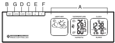
A DISPLAY
B MEMORY [MEM] BUTTON
Recalls the maximum or minimum temperature and humidity of main and remote unit
C [MODE] BUTTON
Toggles the display modes and confirms entry while setting the values for display
D [ALARM] BUTTON
Displays the alarm time or sets the alarm status Displays the temperature alarm or sets the upper or lower limit.
EUP[▲]BUTTON
Advances the value of a setting
F DOWN [▼] BUTTON
Decreases the value of a setting
G [CHANNEL] BUTTON
Displays different sensor temperature & humidity
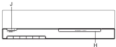
H [SNOOZE/LIGHT] BUTTON
Activate the snooze function and backlight
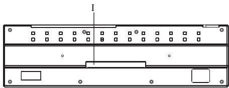
I BATTERY COMPARTMENTS
Accommodates two UM-3 or "AA" size 1.5V batteries
J [ALERT] BUTTON
The sound of the weather forecast alert can be turned "ON" or "OFF".
64
MAIN FEATURES:
THERMO/HYGRO REMOTE UNIT
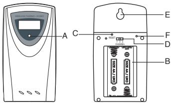
A LED INDICATOR
Flashes once when the remote unit transmits a reading. Flashes twice when low battery is detected on sensor unit.
B BATTERY COMPARTMENT
Accommodates two AA-size batteries.
C RESET BUTTON
Press to reset all setting if you have selected different channel.
D CHANNEL SELECTOR
Select the channel before you install batteries.
E WALL-MOUNT RECESSED HOLE
Supports the remote until in wall-mounting.
F°C/°FBUTTON
65
2. GETTING STARTED
-
Insert batteries for remote units before doing so for the main unit.
-
Position the remote unit and main unit within effective transmission range, which, in usual circumstances, is 20 to 30 meters.
Note that the effective range is vastly affected by the building materials and where the main and remote units are positioned.
Try various set-ups for best result.
Though the remote units are weather proof, they should
be placed away from direct sunlight, rain or snow.
2b) BATTERY INSTALLATION: REMOTE UNITS
- Remove the screws on the battery compartment. 2. Select the channel.
- Install 2 batteries (UM-3 or "AA" size 1.5V ) strictly according to the polarities shown.
- Replace the battery compartment door and secure its screws.
2c) BATTERY INSTALLATION: MAIN UNIT
- Open the battery compartment door.
- Install 2 batteries (UM-3 or "AA" size 1.5V ) strictly according to the polarities shown.
- Replace the battery compartment door.
2d) LOW BATTERY WARNING
If it's time to replace batteries for the remote sensors or the unit, the respective low-battery indicator [**] will show up on the outdoor temperature display (for the thermo/hygro sensor) or on the clock display (for the unit).
66
2e)GETTING STARTED
SETTING UP THE REMOTE SENSORS
a. Once batteries are in place for the remote unit, they will start transmitting temperature and humidity readings at around 45 seconds intervals.
The main unit will also start searching for signals for about two minutes once batteries are installed. 10 seconds upon successful reception, the outdoors temperatures and humidity will be displayed.
b. If no signals are received, blanks "..." will be displayed. Hold [▼] for 2 seconds to enforce another search for about 2 minutes. This is useful in synchronizing the transmission and reception of the remote and main units.
Repeat this step whenever you find discrepancies between the reading shown on the main unit and that on the remote unit.
67
3. WEATHER FORECAST
3a) WEATHER FORECAST
The unit is capable of detecting atmospheric pressure changes. Based on collected data, it can predict the weather for the forthcoming 12 to 24 hours.
| Symbols | |||
| Forecast | Sunny | Slightly Cloudy | Cloudy |
| Little rainy | Heavy rainy | Snowy | heavy snowy |
3b) Weather Forecast Alert
A weather forecast alert alarm will go on when the weather forecast change to one of the status below: Heavy rain, heavy snowy or unstable stormy weather. The Weather Display backlight will be lighting up 2 minutes, the beep sound turns on and the storm symbol will be shown on the display. To deactivate the sound alert switch the [ALERT] button to "OFF".
68
NOTE:
- It is not necessary and not possible to adjust the altitude of the weather station. After the initial start-up of the weather station, a first forecast will be made within the first 24 hours of operation.
- In periods of long stable weather conditions, it becomes difficult to make a reliable forecast.
- The weather forecast is solely calculated on the basis of barometric air pressure changes.
- The probability of a correct weather forecast is approximately 70% and is valid for an area of approx. 20 - 30km around the location of the weather station.
- The forecast "Sunny" means at night "cloudless weather". Fogies not indicated by the weather station as this can occur with different weather conditions.
- If you travel with become impossible due to changes in altitude and location. You'll have to wait up to 24 hour so that the weather station can calculate a new forecast based on the conditions at the new location.
3b) BAROMETRIC PRESSURETREND
The atmospheric pressure indicator, in the weather forecast window, uses arrows to indicate if the atmospheric pressure is increasing, remaining stable, or decreasing.
| Arrow indicator | TREND | TREND | TREND |
| Pressure Trend | Rising | Steady | Falling |
69
4. THERMOMETER / HUMIDITY
4a) HOW TO CHECK REMOTE AND INDOOR TEMPERATURES
The wave display on the outdoors temperature indicates the reception of the remote unit is in good order. If no readings are received from the remote unit for more than two minutes, blanks *** will be displayed until further readings are successfully searched. Check the remote unit is sound and secure. You can wait for a little while or Hold [▼] for 2 seconds to enforce an immediate search. If the temperature or humidity goes above or below than the measuring range of the main unit or the remote unit (stated in specification), the display will show ***: & "HHH" or "LLL," respectively. The unit can be set to automatically scan and display readings from the remote sensors, the display will show the readings from one channel for about 4-seconds and then proceed to the next channel display. -To activate the remote-sensor scanning mode: Press and the hold the button [CHANNEL] for 2 seconds. -To deactivate the remote-sensor scanning mode: Press and the hold the button [CHANNEL] for 2 seconds.
4b) HOW TO READ THE KINETIC WAVE DISPLAY
The kinetic wave display shows the signal receiving status of the main unit. There are three possible forms:
| The unit is in searching mode. | . |
| Temperature readings are securely registered. | . |
| No signals. | ••°C |
70
4c) MAXIMUM AND MINIMUM TEMPERATURES AND HUM
The maximum and minimum recorded indoor temperature, humidity and outdoor temperatures will be automatically stored in memory. To display them, Press [MEM] once to display the maximum readings and again the minimum readings. The respective indicators,
[ MAX ] or [ MIN ] will be displayed.
To clear the memory, hold down [MEM] for two seconds. The maximum and minimum readings will be erased. If you press [MEM] now, the maximum and minimum readings will have the same values as the current ones until different readings are recorded.
4d) TEMPERATURE ALARM
Weather Station is equipped with a temperature alarm whereby a user-defined temperature can be selected. When the selected temperature is reached an acoustic alarm will be initiated. Temperature alarm is programmed as follows:
- Press the [TEMPALARM] button.
- Hold the [TEMPALARM] button for 2 seconds.
- Select the desired temperature for the alarm by using the [▲] or [▼] buttons.
With one further pressing of the TEMPALARM button the data entered is confirmed.
71
4e) TEMPERATURE AND HUMIDITY TREND
The trend indicator shows the trend of temperatures and humidity collected at that particular remote sight. Three trends: rising, steady, and falling will be shown.
| Arrow indicator | TREND | TREND | TREND |
| Temperature Humidity Trend | Rising | Steady | Falling |
4f) COMFORT LEVEL INDICATORS
The comfort level indicators COM, WET or DRY will tell you if the current environment is comfortable, too wet or too dry. The comfort indicators will appear on the display of the main unit when the following conditions are satisfied:
75
| Indicator displays on the unit | Temperature Range | Humidity Range | Shows that the Current Environment |
| COM | 20°C to 25°C (68°F to 77°F) | 40%RH-70%RH | Ideal range for both relative humidity and temperature |
| WET | -5°C + 50°C (23°F - 122°F) | OVER70%RH | Contains excess moisture |
| DRY | -5°C + 50°C (23°F - 122°F) | Below40%RH | Contains inadequate moisture |
| No Indicator | Less than 20°C (68°F) or More than 25°C (77°F) | 40%Rhto70%RH | No comment |
72
5. RADIO CONTROLLED CLOCK
5a) HOW TO SET THE RADIO CONTROLLED CLOCK
- After the batteries are installed. The clock will automatically search the radio signal. It takes about 3-5 minutes to finish this process.
- If user wishes to disable the auto-reception feature, hold the [▲] button for 2 seconds to disable it.
- To enable the auto-reception feature again, holds the "Up" for 2 seconds again to force it receive and allow it receive at desired time.
- If the radio signal is received, the date & time will be set automatically with radio control signal icon [ ] turns on.
- If the clock fails to receive the time signal, it will be show as [1] icon. Then user can set the time manually.
5b)CALENDAR CLOCK DISPLAY MODES
The clock and the calendar share the same section of the display. The calendar is displayed in a day-month format. Each press on the [MODE] button will change the display between clock with second, clock with day of week, zone time with day of week. zone time with second and day-month.
73
5c) HOW TO SET THE CLOCK MANUALLY
To set the clock manually, hold [MODE] for two seconds it will show the weekday language. Use [▼] or [▲] to change it. Press [MODE] to confirm. Repeat the same procedure to set display language, °C/°F, UVI/MED/h, year, month, date, date-month format, 12/24, hour and minute.
During the setting, press and hold [▼] or [▲] will increase or decrease the value rapidly. For display language, you can choose among English (En) German (DE), French (Fr), Italian (IT) and Spanish (SP) in that order. If there is an item you do not wish to change, simply press [MODE] to bypass the item. When you finished the change, press [MODE] to exit. The display will return to the clock mode.
5d) HOW TO SET THE 2. TIME ZONE
To set the 2. time zone, change to the 2. time zone clock mode and hold [MODE] for two seconds. Use [▲] or [▼] to change it from -13h to +15h. When you finished the change, press [MODE] to exit. The display will return to the 2. time zone clock mode.
5e) DISABLE THE RECEPTION OF
THE RADIO CONTROLLED CLOCK
If you are using this product outside the central European.
timezone, you may disable the reception of the radio
controlled clock, Press min. 3 Seconds the key [ ] to
disable the automatic time signal reception. The reception
signal [ ] will then disappear from the display.
To re-enable the time signal reception, press again for
min. 3 Seconds the [ ] key.
6.BELL/ALARM
6a) HOW TO SET AND ARM THE ALARM
To set an alarm,
1. Press [ALARM] once to display alarm time. If the alarm is disarmed, the time will be displayed as "OFF".
2. Hold [ALARM] for two seconds. The hour digits will blink.
3. Enter the hour using [ ] or [ ]
4. Press [ALARM]. The minute digits will blink.
5. Enter the minutes using [] or [] .
6. Press [ALARM] to exit.
7. Repeat the same procedure to set single alarm.
To set the zone time,
1. Press [MODE] until at zone time display mode,
2. Hold [MODE] for two seconds, the zone time offset will be displayed.
3. Enter the offset using [] or [] .
4. Press [MODE] to exit.
The alarm "W" "S" and "Pre-AL" icons will be displayed indicating which alarm is armed. You can also arm or disarm an alarm by pressing the [▲], [▼] button at alarm display mode. Press [MODE] to return to clock display mode.
6c) SNOOZE FEATURE
When the alarm sound is on, press the snooze key enter snooze mode. After 8 minutes, alarm sound will be wake up automatically. The snooze cycle will be restarted if you press the snooze key again. If you leave the alarm sound on for 2 minutes, it will enter snooze mode automatically with maximum 3 times.
6d) HOW TO STOP AN ALARM
Press [ALARM] on the unit to stop an alarm.
6e)ALARM FEATURE
- Weekday Alarm
The alarm sound will be activated and the icon will be flashed on weekday when it is armed and the alarm time is reach.
- Single Alarm
The alarm sound will be activated and the icon will be flashed once when it is armed and the alarm time is reach. Once it finished, it will be disabled automatically.
- Pre-Alarm
The pre-alarm sound will be activated and the icon will be flashed if outdoor temperature under or equal two degree C. Which is programmable 15, 30, 45, 60 or 90 minutes earlier than the weekday alarm or single alarm time.
7. SPECIFICATIONS
Temperature Measurement Main unit
Indoor Temperature measurement
Proposed operating range
0^ to +50.0^
32.0°F to 122.0°F
Humidity Measuring range
: R.H. 10% to 95% .
at 25^(77^)
Temperature resolution
0.1°C
0.2°E
Humidity resolution
:1%R.H
Remote unit
Proposed operating range
: -20°C to + 60°C
-4°F to 140°F
Temperature resolution
:0.1°C
0.2°E
RF Transmission Frequency
:433MHz
Maximum No. of Remote unit
:3
RF Transmission Range
: Maximum 30
meters
Temperature sensing cycle
(open area)
around 43 47
seconds
Relative Humidity Measurement
: 10% RH to
Remote relative humidity
95%RH
measurement range
:1%RH
Resolution
Power
Main unit
:use2pcsUM-3or
"AA" 1.5V battery
Remote sensing unit
:use2pcsUM-3or
"AA" 1.5V battery
Weight
Main unit
:326g
(without battery)
Remote sensing unit
:62g
(without battery)
Dimension
Main unit
This product is engineered to give you years of satisfactory service if you handle it carefully. Here are a few precautions:
- Do not immerse the unit in water.
- Do not clean the unit with abrasive or corrosive materials. They may scratch the plastic parts and corrode the electronic circuit.
- Do not subject the unit to excessive force, shock, dust, temperature or humidity, which may result in malfunction, shorter electronic life span, damaged battery and distorted parts.
- Do not tamper with the unit's internal components. Doing so will invalidate the warranty on the unit and may cause unnecessary damage. The unit contains no user-serviceable parts.
- Only use fresh batteries as specified in the user's manual. Do not mix new and old batteries as the old ones may leak.
- Always read the user's manual thoroughly before operating the unit.
CAUTION
- The content of this manual is subject to change without further notice.
- Due to printing limitation, the displays shown in this manual may differ from the actual display.
- The contents of this manual may not be reproduced without the permission of the manufacturer.
78
EC-DECLARATION OF CONFORMITY
Product: TE555X/HBR555t
This product contains the approved transmitter and complies with the essential requirements of Article 3 of the R&TTE 1999/5/EC Directives, if used for its intended use and that the following standard(s) has/have been applied:
Efficient use of radio frequency spectrum
(Article 3.2 of the R&TTE Directive)
applied standard(s)
EN 300 220-1,3:2000
Electromagnetic compatibility
(Article 3.1.b of the R&TTE Directive)
applied standard(s)
EN 301 489-1,3:2000
applied standard(s)
EN 300 339:2000
Additional information:
The product is therefore conform with the Low Voltage Directive 73/23/EC, the EMC Directive 89/336/EC and R&TTE Directive 1999/5/EC (appendix II) and carries the respective CE marking.
RTTE Compliant Countries :
All EU countries, Switzerland

QAMANAGER:H.Y.WANG
K.S plastic factory
Guan Lan / Shen Shen / China

C∈0125①
79