
SPARGAS 11 P - Burner BALTUR - Free user manual and instructions
Find the device manual for free SPARGAS 11 P BALTUR in PDF.
User questions about SPARGAS 11 P BALTUR
0 question about this device. Answer the ones you know or ask your own.
Ask a new question about this device
Download the instructions for your Burner in PDF format for free! Find your manual SPARGAS 11 P - BALTUR and take your electronic device back in hand. On this page are published all the documents necessary for the use of your device. SPARGAS 11 P by BALTUR.
USER MANUAL SPARGAS 11 P BALTUR
Manufacturer's declaration
NOTE: this declaration is not valid with regard to EC or UNI Standards for gas burners or the gas part of duel-fuel burners (gas/light oil or gas/heavy oil) when such burners have been ordered in non-compliance with the EC Standard or Italian UNI Standard because they are to be used for special purposes not provided for in the above-mentioned standards.
- BALTUR guarantees the "CE" certification provided that the burner is coupled to the "CE" gas train supplied by BALTUR and the "CE" gas line accessories (on request).
- Technical specifications 8
- Application of the burner to boiler 23
- Electrical connections - Descriptions of operations - Natural gas starting up and regulation Air regulation on the combustion head - Maintenance - Use of the burner 24
- Gas burner controls. 27
Combined DUNGS gas valve (monobloc) MB-ZRDLE...B01-B02 31
Notes on use of propane (L.P.G) - Operation problems 33 - Layout diagram with vaporisation 75
Air regulation principle - Electrodes adjustment 76
Air regulation servomotor 78 - Electric diagram 79
INDICE
PÁGINA
1) Disk head position reference
2) Manual air regulation knob
2.1) Air regulation servomotor (only for P version)
3) 7-pole connector
3.1) 4-pole connector (only for P version)
4) Control box
5) Combustion head
6) Insulating gasket
7) Burner mounting flange
8) Motor
9) Air pressure switch
10) Disk head regulating screw
11) Gas electrovalve
N°BT8721/2 Rev.21/03/90
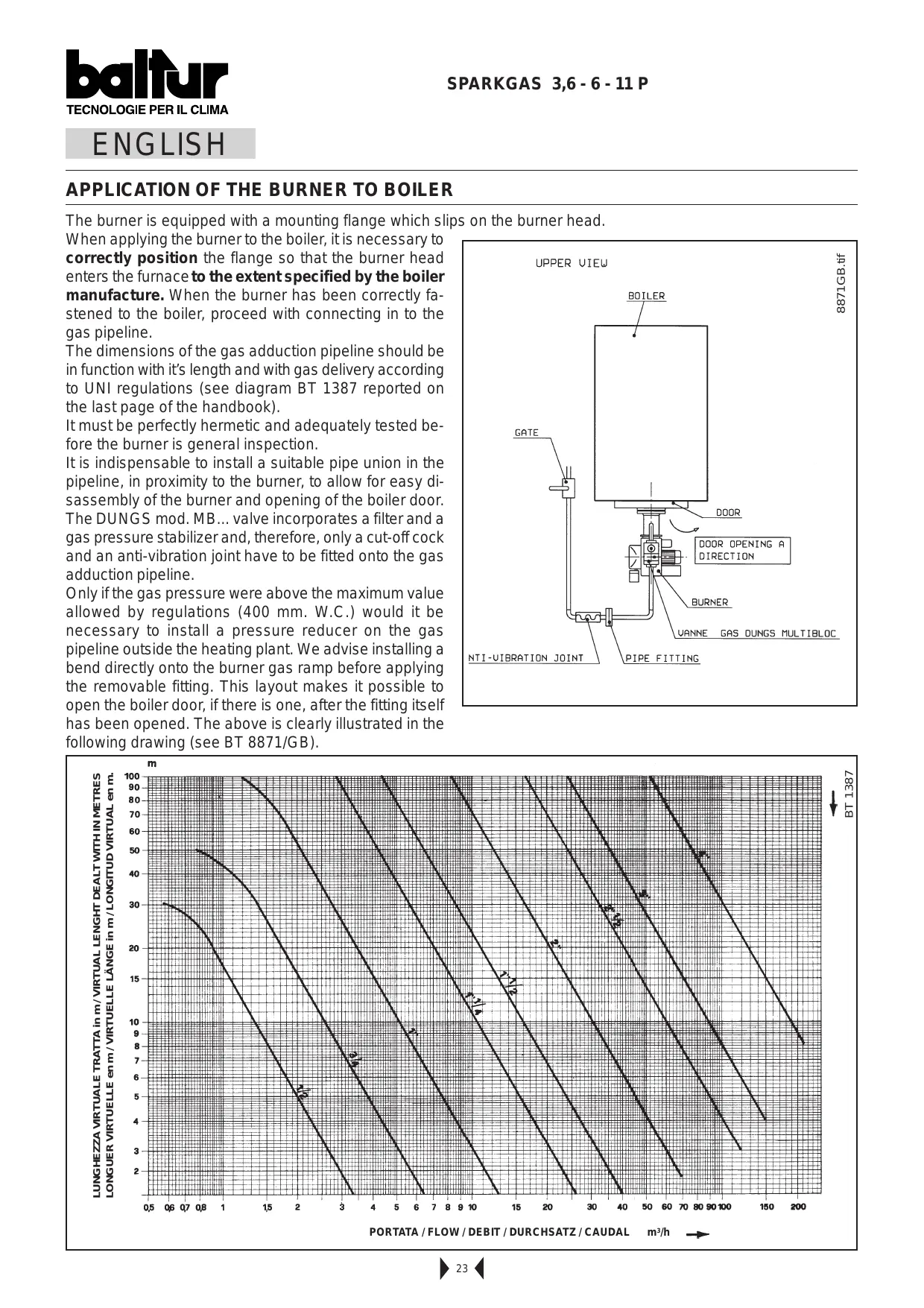
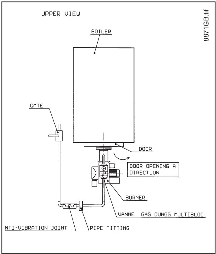
The burner is equipped with a mounting flange which slips on the burner head.
When applying the burner to the boiler, it is necessary to correctly position the flange so that the burner head enters the furnace to the extent specified by the boiler manufacture. When the burner has been correctly fastened to the boiler, proceed with connecting in to the gas pipeline.
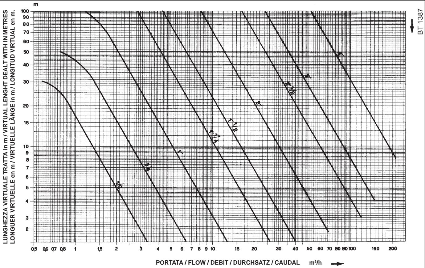
The dimensions of the gas adduction pipeline should be in function with its length and with gas delivery according to UNI regulations (see diagram BT 1387 reported on the last page of the handbook).
It must be perfectly hermetic and adequately tested before the burner is general inspection.
It is indispensable to install a suitable pipe union in the pipeline, in proximity to the burner, to allow for easy disassembly of the burner and opening of the boiler door. The DUNGS mod. MB... valve incorporates a filter and a gas pressure stabilizer and, therefore, only a cut-off cock and an anti-vibration joint have to be fitted onto the gas adduction pipeline.
Only if the gas pressure were above the maximum value allowed by regulations (400 mm. W.C.) would it be necessary to install a pressure reducer on the gas pipeline outside the heating plant. We advise installing a bend directly onto the burner gas ramp before applying the removable fitting. This layout makes it possible to open the boiler door, if there is one, after the fitting itself has been opened. The above is clearly illustrated in the following drawing (see BT 8871/GB).
ELECTRICAL CONNECTIONS
The electric lines should be at an adequate distance from hot parts. It is advisable to make all connections with flexible electric wire. Minimum section of conductors 1.5mm^2 (CEI 64/8 3.1.07).
DESCRIPTION OF OPERATIONS
Switch off the general switch, if the thermostats are off, and voltage goes to the command and control device which, after a short interval (9 second), will start up the burner according to the set program. The fan motor goes into operation and makes the combustion chamber preventilation. At the end of the prevention phase, the ignition procedure will then start and, after 3 seconds, the safety valve and "first flame" (pilot light) valve will open up. A flame will then apper, which will be detected by the flame control device, thus completing the ignition procedure.
The air shutter control servo will then be switched on, which will move to the second flame setting, as set by the operator in each specific case, and at the same time an auxiliary contact on the servo will activate the second flame valve. If the flame does not light, the burner will go into the "safety shutdown" state, 3 second after the opening of the gas valves (pilot and safety). If a "safety shutdown" occurs, the gas valves will be closed immediately.
To go out of the shutdown state, press the red button on the burner unit.
NATURAL GAS STARTING UP AND REGULATION
(for LPG operation see the relative chapter)
In order to proceed with starting up, it's necessary, if the burner is three-phase, to check that the sense of rotation of the motor is correct. If not already done so at the moment of connecting the burner to the gas pipeline, it's indispensable to carry a purge of the air contained in the pipeline.
As a precaution, special care should be taken and doors and windows should be opened. Open the pipe union on the pipeline situated near the burner and then open a little the cut-off cock (or cocks). When the characteristic odour of gas can be smelled, close the cut-off cock. Wait until the gas present in the room has dispersed, and then reconnect the burner to the gas pipeline. Then proceed as follows:
1) Make sure that the discharge of combustion products can take place freely (chimney lock-gates should be open) and that there is water in the boiler.
2) Open as much as considered necessary, the combustion air regulator, (see "servomotor for regulating air shutter type LKS 120-02 (B5-5-51)" and open by about one third the air passage between the head and the flame disk (diffuser) (see "Regulation of the combustion Head").
3) Operate the regulators incorporated in the gas valves in such a way as to obtain the gas delivery presumed necessary.
4) Disconnect the 2nd flame thermostat and give current to the burner by opening the main switch.
The burners is then turned on and carries out the pre-ventilation phase. If the air pressure exceeds that value at which the air pressure switch has been set, the ignition transformer will be connected and, subsequently, the gas valves (safety and 1^st flame) will be inserted.
The valves open completely and gas delivery is limited to the position at which the flow regulator incorporated in the 1^st flame (pilot) valve has been manually regulated. At first ignition, successive "shut downs" could occur, due to the following reasons:
a - The gas pipeline has not been adequately purged of air and therefore the quantity of gas is not sufficient to allow for a stable flame.
b - A "shut down" with flame presence could be caused by flame instability in the ionisation zone, due to and incorrect air/gas ratio. This can be remedied by varying the quantity of air and/or gas delivered, in order to find the correct ratio. It could also be caused by an incorrect distribution of air/gas in the combustion head. This can be corrected by operating the regulation device of the combustion head by closing or opening more the air passage between the head and the gas diffuser. See chapter "regulation of the combustion head".
c - It could happen that the ionisation current is help up by the current discharged from the ignition transformer (the two currents have to run the same course on the burner's "earth") and so the burner goes to "shut down" due to insufficient ionisation. This can be remedied by inverting the input (220V side) of the ignition transformer (change the places of the two wire that take voltage to the transformer). A shut down with flame presence could also be caused by the burner's casing not being properly "grounded".
We must point out that the minimum value of the ionisation current to ensure the working of the control box is shown in the electrical diagram; normally the ionisation current is decidedly higher. To check the ionisation current, connect a microammeter with an adequate scale "in series" to the ionisation circuit. The cable of the ionisation electrode is equipped with a connector (see circuit diagram) to facilitate the micro-ammeter connection. The high isolation wire that comes from the electrode must be inserted to the negative (sign -) of the microammeter.
TECOLOGIE PER IL CLIMA
5) With the burner on, adapt delivery to that desired (methane gas = 8550 Kcal/m ^3 ) by reading the meter. Take two readings, the second one exactly one minute after the first one. The difference between the two readings should be multiplied by in order to obtain the flow per hour (60 minutes).
This output can be modified by operating the special regulator incorporated in the valve (see the last pages for a description of how to regulate the valves).
6) Control that combustion occurs correctly by using the appropriate instruments CO_2 = about 10% for methane gas - CO max. = 0.1% .
7) After regulation, turn the burner off and on again several times to check that ignition occurs correctly.
With the burner disconnected from the main switch, connect the 2^nd flame thermostat and regulate the special device on the servomotor in such a way as to obtain an opening of the air shutter presumed necessary for the 2^nd flame (see BT 8920/1).
Open as well the gas flow regulator incorporated in the valve to allow for the correct delivery presumed necessary for the 2^nd flame (main flame).
8) Now close the main switch to start up the burner. When the burner has started up it is necessary to check, as previously shown, the gas delivery and the combustion with the appropriate instruments.
When the results are known, if necessary, proceed with varying the gas delivery and the relative combustion air in order to adapt delivery to that required for the specific case (boiler potentiality). It is also necessary to check if the CO2 and CO values are adequate ( CO2 max. = about 10% for Methane gas and CO = 0.1% ).
9) Control the efficiency of the safety devices: the "shut down" (by detaching the ionisation electrode cable), the air pressure switch, the gas pressure switch, the gas pressure switch and the thermostats). N.B. The pressure switch is self-controlled and treate it must close the contact, which is foreseen to be closed at rest, (fan stops and consequently there is an absence of air pressure in the burner); if it does not, the control box will not be inserted (the burner remains at as standstill). It must be specified that if the contact is not closed during working, the control box will carry out its cycle, but the ignition transformer will not be inserted and the gas valves will not open. Consequently, the burner will go to shut down. Check that the air pressure switch functions properly with burner operating at 1^st flame only, increase the regulating value until it reaches intervention point and the burner should go to shut down. To ublock the burner, press the special pushbutton and return the pressure switch regulator to a sufficient value in order to measure the air pressure existing during the pre-ventilation phase.
AIR REGULATION ON THE COMBUSTION HEAD
(see BT9481/1 and BT9485/2)
The combustion head is equipped with a regulating device which closes and opens the air passage between the disk and the head. By closing the passage it's possible to achieve high pressure upstream the disk for low inputs as well. High velocity and turbulence ensure a better penetration in the fuel, an optimum mixture and good flame stability. It might be necessary to have high air pressure upstream the disk in order to avoid flame pulsation and it's considered practically indispensable when the burner is operating with a pressurised furnace and/or thermal load. It's evident from the above, that the device which closes the air on the combustion head should be put in such a position as to always obtain a decidedly high air pressure value behind the disk. It's advisable to regulate in such a way as to achieve a closing of the air on the head; this will necessitate a considerable opening of the air shutter which regulates the flow to the burner's fan suction. Obviously, these adjustments should be carried out when the burner is operating at maximum delivery desired. In practice, start regulating by putting the device which closes the air on the combustion head in an intermediate position, start up the burner and make trial adjustments as previously described.
When maximum delivery desired has been reached, proceed with correcting the position of the device which closes the air on the combustion head; move it backwards or forwards in such a way as to obtain an air flow suitable to the delivery, with the air regulation shutter in suction considerably open.
When reducing the air passage on the combustion head, avoid closing it completely.
N.B. Check that ignition occurs regularly, because if the passage between the disk and the head is closed, it could occur that the air velocity is so high as to render ignition difficult. If this happens, gradually open the regulator until it reaches the correct position and ignition occurs regularly. This position should be definitive. It should also be remembered that, for the 1^st flame, it is preferable to limit the quantity of air to that which is strictly indispensable in order to have safe ignition even in the most difficult circumstances.
MAINTENANCE
The burner does not require special maintenance, but it is good practice to check periodically that the gas filter is clean and that the ignition electrode is efficient. It is also necessary to verify that the ignition electrode's spark is produced between the same electrode and the disk. The combustion head may need cleaning.
During re-assembly, special attention must be paid to centring exactly the electrodes (ignition and flame detection) in order to avoid them going to earth or short-circuiting which would result in the "shut down" of the burner.
USE OF THE BURNER
The burner operates fully automatically, therefore it is non necessary to carry out any kind at adjustment during its operating. The "block" position is a safety position reached by the burner automatically when some of the components of the burners or the plant do not work properly. It is necessary to check then whether the cause to the problem is a dangerous one before unblocking the burner. The causes to the block may be temporary, for example when air in inside the pipes. When it is unblocked, the burner starts operating properly.
If the burner stops three or four times at a stretch, it is necessary either to loock for the problem and solve it or ask for the intervention of the after sales service. The burner can remain in the "block" position without any limit in time.
In emergency cases it is advisable to close the fuel valve, and to disconnect the burner electrically.
LMG2...CONTROL BOX SPECIFICATIONS
Type summary
The type references contained in the following table refer to LMG.... With no plug-in base and with no flame detector.
For ordering information on bases and other accessories, refer to "Ordering".
| Type of flame detector | Type reference LMG2... | tw s min. 1) | t1 s min. | TSA s max. | t3n s ca. | t3 s ca. | t4 s ca. | t10 s min. 1) | t11 s max. 2) | t12 s max. 2) | Behavior in the event of flame fail. dur. operat |
| Burner controls for pre-purging with low flame air volume, without actuator control | |||||||||||
| Detector electrode (FE) or UV detector QRA... with AGQ2...A27 | LMG21.130A27 3) | 2.5 | 7 | 3 | 2 | 2 | 8 | 5 | - | - | Lockout |
| LMG21.230A27 4) | 2.5 | 20 | 3 | 2 | 2 | 8 | 5 | - | - | Lockout | |
| LMG21.330A27 4) | 2.5 | 30 | 3 | 2 | 2 | 8 | 5 | - | - | Lockout | |
| LMG21.350A27 4) | 2.5 | 30 | 5 | 4 | 2 | 10 | 5 | - | - | Lockout | |
| LMG21.650A27 4) | 2.5 | 50 | 5 | 4 | 2 | 10 | 5 | - | - | Lockout | |
| Burner controls for pre-purging with nominal air volume, with actuator control | |||||||||||
| Detector electrode (FE) or UV detector QRA... with AGQ2...A27 | LMG22.130A27 3) | 2.5 | 7 | 3 | 2 | 3 | 8 | 3 | 12 | 12 | Lockout |
| LMG22.230A27 4) | 2.5 | 20 | 3 | 2 | 3 | 8 | 3 | 16.5 | 16.5 | Lockout | |
| LMG22.233A27 | 2.5 | 20 | 3 | 2 | 3 | 8 | 3 | 30 | 30 | Lockout | |
| LMG22.330A27 4) | 2.5 | 30 | 3 | 2 | 3 | 8 | 3 | 12 | 11 | Lockout | |
| LMG22.330A270 4) 5) | 2.5 | 30 | 3 | 2 | 3 | 8 | 3 | 12 | 11 | Lockout | |
| Burner controls for pre-purging with low flame air volume, without actuator control | |||||||||||
| Detector electrode (FE) or UV detector QRA... with AGQ2...A27 | LMG25.230A27 | 2.5 | 20 | 3 | 2 | 2 | 8 | 5 | - | - | Max. 3 repeat. |
| LMG25.330A27 | 2.5 | 30 | 3 | 2 | 2 | 8 | 5 | - | - | Max. 3 repeat. | |
| LMG25.350A27 | 2.5 | 30 | 5 | 4 | 2 | 10 | 5 | - | - | Max. 3 repeat. | |
Legend
| tw | Waiting time | T4 | Interval «TSAEnde-BV2» or «BV1-LR» |
| t1 | Checked pre-purge time | T10 | Specified time for air pressure signal |
| TSA | Ignition safety time | T11 | Programmed opening time for actuator «SA» |
| t3 | Pre-ignition time | T12 | Programmed closing time for actuator «SA» |
| T3n | Ignition time during «TSA» | ||
| 1) | Max. 65 s | 4) | Also suited for use with direct fired air heater |
| 2) | Max. running time available for actuators «SA», the actuator's running time must be shorter | 5) | Without integral fuse; use only in connection with AGK86... or with an external microfuse of max. 6 |
| 3) | Also suited for use with flash-steam generators |
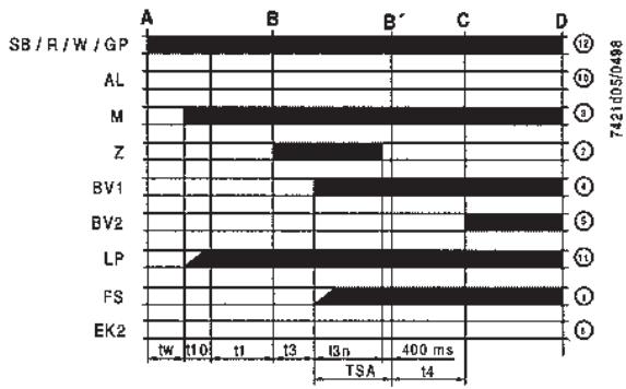
Functions
LMG21.../LMG25...
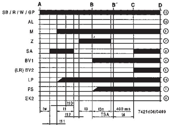
LMG22...
Legend
| A | Start command (switching on by «R») | B-B' | Interval for establishment of flame |
| C | Operating position of burner reached | C-D | Burner operation (heating production) |
| D | Controlled shutdown by «R» | ||
| • Burner is immediately shut down | |||
| • Bumer control is immediately ready for new startup | |||
| AL | Fault status signal (alarm) | M | Fan motor |
| BV... | Fuel valve | R | Control thermostat / pressurestat |
| EK2 | Remote reset button | SA | Actuators |
| FS | Flame signal | SB | Safety limit thermostat |
| GP | Gas pressure monitor | W | Limit thermostat / pressure monitor |
| LP | Air pressure monitor | Z | Ignition transformer |
| LR | Load controller |
| Prerequisites for startup | ·Burner control is reset ·All contacts in the line are closed ·Fan motor «M» or AGK25 is connected ·Air pressure monitor «LP» is in idle position ·No undervoltage · |
| Undervoltage | Safety shutdown in the event - the mains voltage is lower than typically AC 160 V - a restart is made when the mains voltage exceeds AC 195 V |
| Checked intermittent operation | After no more than 24 hours of continuous operation, the burner control initiates a safety shutdown, followed by a restart. |
| Reversed polarity protection | If the connections of line (terminal 12) and neutral (terminal 2) have been exchanged, the burner control will initiate lockout at the end of «TSA». |
| Control program in the event of fault | ·If puts will immediately be deactivated (<1 s) ·On restoration of power, a restart will be made with the full program sequence ·If the operating voltage drops below the undervoltage threshold (for threshold, refer to «Functions», a restart will be made with the full program sequence ·If there is a premature faulty flame signal during «t1» ⇒ Lockout ·If the contact of the air pressure monitor «LP» has welded in the working position: prevention of startup and, after 65 seconds, lockout ·If the contact of the air pressure monitor «LP» has welded in the idle position: lockout at the end of «t10*/ ·If there is no air pressure on completion of «t10» ⇒ Lockout ·If the burner does not ignite during «TSA» ⇒ Lockout ·If flame is lost during operation →LMG21... / LMG22... lockout →LMG25... three repetitions |
| Lockout | Lockout cannot be changed and takes place 10 seconds after safety shutdown. A mains voltage failure during that period of time leads to a restart. |
| Resetting the LMG2... | When lockout occurs, the burner control can immediately be reset! In that case, keep lockout reset button depressed for a minimum of 0.5 seconds and a maximum of 3 seconds! |
Operating concept
| ·Burner control has initiated lockout ⇒Red fault LED on | ·Reset Press lockout reset button for 0.5...3 s |
| ·Diagnosis of cause of fault - Wait >10 s - Press lockout reset button for >3 s - Read blink code of red fault LED ⇒«Error code table» | |
| ·Burner control in operation ⇒Green flame signal LED on | ·Restart Press lockout reset button for 0.5...3 s |
| ·Read flame establishment time - Press lockout reset button for >3 s - Read blink code of green flame signal LED ⇒«Error code table» |
Diagnosis of cause of fault
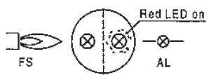
After lockout, the red fault LED is steady on.
For reading the cause of fault, refer to the blink code given in the following table:
| Error code table | |
| Blink code | Possible cause |
| 2 x blink** | No establishment of flame at the end of «TSA»- Faulty or soiled detector electrode-Faulty or soiled fuel valves-Poor adjustment of burner |
| 3 x blink*** | Air pressure monitor does not close- «LP» faulty- «LP» incorrectly adjusted- Fan motor does not run |
| 4 x blink**** | Air pressure monitor does not open or extraneous light on burner startup- «LP» faulty- «LP» incorrectly adjusted |
| 5 x blink***** | Extraneous light during pre-purging- Or internal device fault |
| 7 x blink********** | Loss of flame during operation-Poor adjustment of burner-Faulty or soiled fuel valves- Short-circuit between detector electrode and ground |
| 8...17 x blink********** | Free |
| 18 x blink********** | Air pressure monitor opens during pre-purging or operation- «LP» incorrectly adjusted-Four times loss of flame during operation (LMG25) |
| 19 x blink********** | Faulty output contact-Wiring error- External power supply on output terminal |
| 20 x blink********** | Internal device fault |
During the time the cause of the fault is diagnosed, the control outputs are deactivated.
The burner remains shut down
- Exception: fault status signal «AL» at terminal 10
The burner is switched on only after a reset is made.
- Press lockout reset button for 0.5...3 seconds
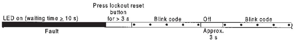
Interrogation of flame establishment time
This function measures the flame establishment time with ionization supervision.
With the AGQ2..., this function cannot be used.
In the running position, the green flame signal LED is steady on.
The flame establishment time is read in the running position according to the following sequence:
Press lockout reset
LED on
button for >3s
Blink code
Off
Blink code
Operation
Approx. 3s
When reading the flame establishment time, the burner is put out of operation.
Reading is in the form of a blink code as multiples of 0.4 s.
The flame establishment time is the period of time from the moment «BVI» opens to the moment the flame signal is detected for the first time
- The flame establishment time remains stored for one startup sequence and is re-ascertained the next time the burner is started up
- During the period of time the flame establishment time is interrogated, the fault status outputs are deactivated:
- Burner remains shut down
It is restarted only after a reset is made - Press lockout reset button for 0.5...3 seconds

Note:
If ignition and ionization electrode are not correctly located, ignition effects on the detector electrode may lead to incorrect measurements.
Flame supervision with detector electrode
| At mains voltage UN = AC 230 V | |
| Detector voltage across terminals 1 and 2 or ground (AC voltmeter Ri ≥ 10 MΩ) | AC 115...230 V |
| Switching thresholds (limit values) | |
| Switching on (flame on) DC ammeter, Ri ≤ 5 kΩ) | ≥ DC 1 μA |
| Switching off (flame off) DC ammeter, Ri ≤ 5 kΩ) | ≤ DC 0.5 μA |
| Requested sensor current for reliable operation | ≥ 2 μA |
| Max. short-circuit current across terminals 1 and 2 or ground (AC ammeter, Ri ≤ 5 kΩ) | AC 50 μA |

Note:
With the same flame quality, the detector current with LMG2... is lower than with LGB2...!
Flame supervision takes place by making use of the conductivity and rectifying effect of hot flame gases.
The flame signal amplifier responds only to the DC current component of the flame signal.
A short-circuit between detector electrode and ground causes the burner to initiate lockout
Measurement circuit
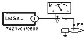
Legend
C-Electrolytic capacitor 100...470 F DC 10...25 V
FE- Detector electrode
M-Micrometer (Ri . = 5000)
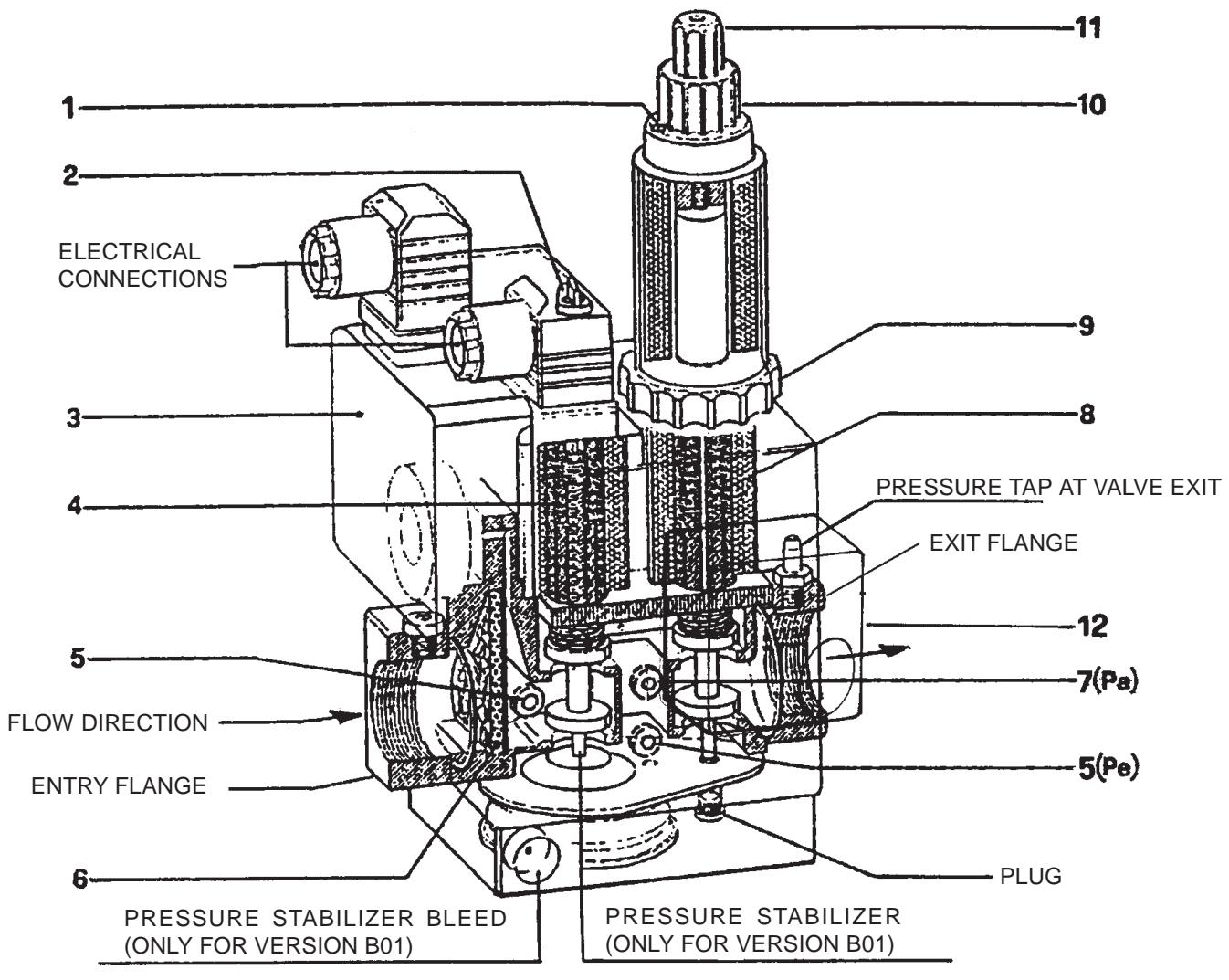
1- Locking screw for 1st and 2nd flame regulators
2- Cover for regulating screw of pressure stabilizer(only for version B01)
3-Gas pressure switch (minimum)
4- Safety valve
5- Pressure tap at gas entry
6-Filter
7- Pressure tap after pressure stabilizer (Pa)
8- Principle valve (1st and 2nd flame)
9- Regulating ring 1st flame delivery
10- Regulating knob 2nd flame delivery
11- Protective cover (can be used as a knob) of
regulating device for the initial rapid release.
12- Gas pressure switch (maximum) (only for version B02 and B01 S50)
Note: to increase delivery, rotate the delivery devices in an anti-clockwise direction; to decrease delivery, rotate them in a clockwise direction. The versions B02 and B01 S50 are employed with liquid gas (LPG)
The monobloc DUNGS Model MB-ZRDLE is made up of:
a) Minimum gas pressure switch (3) and maximum gas pressure (12)
b) Gas filter (6)
c) Pressure regulator (stabilizer) (2) (only for version B01)
d) Safety valve (incorporated in the pressure regulator) which opens and closes rapidly (4)
e) Principle valve with two positions (1st flame and 2nd flame) which opens slowly with an adjustable initial rapid release and rapid closing (8).
Before proceeding with regulation, read the following:
1) It is possible to reach the gas filter (6) in order to clean it, by removing one of the two side closing plates.
2) The pressure stabilizer can be regulated from 40 to 200mm . W.C. by manoeuvring its regulating screw. It can be reached by sliding the cover (2) to one side. The and viceversa is about 60 turns. Do not force against the end-of-the-run position. Before starting up the burner, give the screw at least 15 turns towards the + sign. Around the screw are arrows with symbols which indicate the sense of rotation to increase the pressure (in a clockwise direction) and the sense of rotation to decrease pressure (in an anti-clockwise direction).
The stabilizer hermetically closes from "upstream" to "downstream" when there is no gas flow. Different springs to obtain different pressure values form those described above are not foreseen.
To regulate the pressure stabilizer, connect a water manometer to the rubber tube holder installed on the valve, to tap Pa (7), in correspondence with the stabilizer exit.
3) It is not necessary to regulate the rapid opening and closing safety valve (4).
4) Principle valve (8).
Regulating the initial rapid release effects the 1st and 2nd opening positions of the valve.
Regulation of the rapid release and of the hydraulic brake modify the 1st and 2nd positions of the valve in proportion to the output regulated. To carry out regulation, unscrew the protection cover (11) and use the back part of it as a tool to turn the pin.
Rotation in a clockwise direction = minor rapid release
Rotation in an anti-clockwise direction = greater rapid release
REGULATING THE FIRST POSITION (1ST FLAME)
Loosen the screw with the protruding cylindrical head (1)
Give the knob (10), which regulates the output for the 2nd flame, at least one turn in the direction of the arrow which indicates the + sign (anti-clockwise direction).
ATTENTION: If this knob which regulates the 2nd flame is not given at least one turn towards the + sign, the valve will not open in the 1st position.
Rotate the regulating ring (9) of the 1st flame in the direction indicated by the arrow towards the + sign (anti-clockwise direction). As an indication, this should be a little more than two turns from the end-of-the-run position.
Then, when the 1st flame only is alight, rotate adequately ring (9) in order to obtain the gas delivery desired.
The complete run of the output regulator, from the - position to the + position, and viceversa, is about three and a half turns. Rotation of the regulator in a clockwise direction, determines a reduction in delivery; rotation in an anticlockwise direction increase delivery.
REGULATING THE SECOND POSITION (2ST FLAME)
Loosen the screw with the protruding cylindrical head (1)
Rotate the knob (10) in the direction indicated by the arrow for the + sign (anti-clockwise direction) as considered necessary in order to obtain the gas delivery required for the 2nd flame.
The complete run of the regulator from the - position to the + position, and viceversa, is about FIVE turns. Rotate in a clockwise direction to determine a reduction in delivery and in an anti-clockwise direction to increase it.
After regulating the gas delivery for the 1st and 2nd flame, remember to tighten home the screw (1) to avoid the regulator moving out of the position at which it has been set.
DETAILS OF TERMINAL BOARD FOR VALVE MB-ZRDLE...
| VALVE MODEL | INLET MAX PRESSURE (PE) mbar | ADJUSTTABLE OUTLET PRESSURE FROM THE STABILIZER (PA) mbar | TYPE OF GAS |
| MB ...B01 S 20 | 200 | from 4 to 20 | Gas maturale |
| MB ... B01 S 50 | 360 | from 4 to 50 | L.P.G |
| MB ... B02 | 360 | L.P.G. |
We think it would be useful to inform you on a few points regarding use of liquid propane gas (L.P.G.).
1) Approximate evaluation of running costs
a) 1m^3 of liquid gas in gaseous state has heating power inferior by about 22.000 Kcal.
b) to obtain 1m^3 of gas about 2Kg of liquid gas are required. This is equal to about 4 litres of liquid gas.
According to the above, it can be deduced that by using liquid gas (L.P.G.) the following approximate equivalence is obtained:
22.000 Kcal = 1 m³ (in gaseous state) = 2 Kg of L.P.G. (liquid) = 4 litres L.P.G. (liquid). From this, running costs can be calculated.
2) Safety measures
Liquid gas (L.P.G.) has, in it gaseous state, a specific gravity superior to that of air (specific gravity of propane gas in relation to air = 1,56) and therefore does not disperse in air like natural gas, which has a lower specific gravity (specific gravity of natural gas in relation to air = 0,60), but precipitates and spreads at ground level as if it were a liquid. In view of the above principle, the Ministero dell'Interno (Home Office) has set limitations for use of Liquid Gas in circular n° 412/4183 of 6 February 1975. We will look into the points we think most important:
a) Liquid Gas (L.P.G.) for burners and/or boilers can only be used in rooms above ground and overlooking open spaces. Installations using liquid gas in basements or cellars are not permitted.
b) Rooms where liquid gas is used must have ventilation inlets without closing devices, located on external walls with a surface of at least 1/15 of the room's area and a minimum of 0.5m^2
At least one third of the entire surface of these inlets must be located in the lower part of the external wall, flush with the floor.
3) Requirements for liquid gas plant to ensure correct operation and safety
Natural gasification, from cylinder unit or tank, can only be used for low power plant. Supply capacity at gaseous stage, depending on tank dimensions and minimum external temperature, is shown in the following table but only as a rough guide.
| Minimum temperature | - 15 °C | - 10 °C | - 5 °C | - 0 °C | + 5 °C |
| Tank 990 I. | 1,6 Kg/h | 2,5 Kg/h | 3,5 Kg/h | 8 Kg/h | 10 Kg/h |
| Tank 3000 I. | 2,5 Kg/h | 4,5 Kg/h | 6,5 Kg/h | 9 Kg/h | 12 Kg/h |
| Tank 5000 I. | 4 Kg/h | 6,5 Kg/h | 11,5 Kg/h | 16 Kg/h | 21 Kg/h |
With the exception of low power plant, for correct operation and safety, it is always essential to install a suitable liquid gas heater (vaporiser) immediately in front of the pressure reducer. The vaporiser is a container built in accordance with Regulations. It has a control thermostat which heats liquid gas by means of an electric resistor or circulation of hot fluid. Reduction of pressure and change of state (from liquid to gas) considerably lowers temperature. In the cold season, the latter easily reaches values of much less than zero degrees.
Any humidity (water) by change present in the liquid gas would change into ice and thus impede correct operation of the reducer (blocked in open position) with consequences that can easily be imagined.
The vaporiser must be installed very near to the reducer to avoid already cooled gas, picked up in liquid form from the tank, reaching the reducer.
Without the vaporiser, it is practically impossible to ensure correct supply of gas in gaseous state in the cold season. Pressure reduction can be carried out by means of a suitable pressure reducer.
Widespread use is also made of plant with two-stage pressure reduction because:
a) it reduces risks of freezing and condensation
b) Pipe diameter between the first and second reducers can be less than that required for single stage reduction. Considerable cost saving can be achieved for large scale networks.
c) Final pressure value is more constant.
For two-stage reduction, install the first reducer near the tank (or at the vaporiser outlet), which reduces pressure to approximately 1 bar. A second pressure reducer is installed outside, before the boiler room and reduces pressure to the boiler supply value (usually 300mm .W.C. = 0,03 bar). For natural gasification, the first-stage regulator must be installed so that any condensate discharges into the tank.
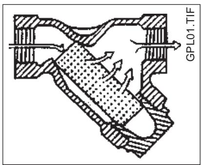
It is necessary to protect this pressurereducer whith a proper filter in order to avoid that any impurities, unexpectedly, reach the reducer thus endangering the correct working.
It is important to point out that the usual filters do not have a cartridge (filter element) enough resistant to this pressure. We can recommend, as a suggestion, to use a common "steam filter" for it is provided with a filter element suitable to undergo very hight pressure, see the fig.. Use a filter having at least the same size as the diameter of the gas intake tube. It is also necessary to point out that the usual gas filter must be installed near the burner.
GENERAL DIAGRAM FOR TWO-STAGE L.P.G. PRESSURE REDUCTION FOR BURNER OR BOILER

N° BT 8721/2GB Rev.21/03/90
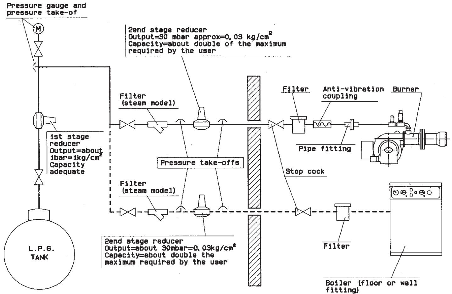
Note: Do not cover pipes and reducers with insulating material
4) Pipe dimension table in accordance to UNI-CIG 7129-72 norms
Capacity in volume (consumption) in m^3/h for propane (L.P.G.) with density of 1,56 (according to UNI 7128-72), calculated for a maximum load loss of 0,5 mbar.
For pressure loss of 1 mbar flow rates must be increased by 45% ;
For pressure loss of 2 mbar flow rates must be increases by 110% .
5) Burner
The burner must be ordered specifically for use with liquid gas (L.P.G.) so that it is equipped with gas valves of sufficient dimensions to ensure correct ignition and gradual regulation. Our valves have dimension is planned for use at a supply pressure of about 300 mm.W.C. We suggest gas pressure be checked at the burner by using a water column pressure gauge.
N.B. Maximum and minimum burner pressure (kcal/h) obviously remains that of the original natural gas burner (L.P.G. has heating power superior to that of natural gas. Therefore, in order to burn fully, it requires air quantity in proportion to the thermal power created).
6) Combustion control
To limit consumption and avoid serious trouble, adjust combustion by using the appropriate instruments. It is absolutely essential to check that the percentage of carbon monoxide (CO) does not exceed maximum permitted value of 0,1% (use a phial analyser or other similar instrument). Please note that our guarantee does not cover burners operating on liquid gas (L.P.G.) in plant for which the above measures have not been taken.
OPERATING ANOMALY
| TYPE OF IRREGULARITY | PROBABLE CAUSE | RIMEDY |
| The burner does not start. | 1) Lack of currente. 2) Gas does not reach the burner. | 1) Check the fuses of the feed line. Check the fuses of the control box. Check the line of the thermostats and the gas pressure switch. 2) Check the opening of the detecting devices located along the feeding pipes. |
| The burner starts but the flame does not ignite. The burner stops consequently. | 1) The gas valves do not open. 2) There is no spark at the electrode. 3) The air pressure switch does not give it's consent to the control box. | 1) Check the valves operation. 2) Check the operation of the ignition transformer. Check the position of the electrodes ends. 3) Check the setting and operation of the air pressure switch. |
| The burner starts and the flame ignites then the burnes stops. | 1) The control electrode does not detect or detects the flame improperly. | 1) Check the position of the control electrode. Check the valve of the ionisation current. |
1) EVALUATION INDICATIVE DU COUT DE FONCTIONNEMENT
1st stage reducer unit
- The vaporizer is considered a dangerous point and should therefore be situated at a safe distance from any building.
- The electrical system must be AD-EP (anti-deflagration-explosion proof).
- The L.P.G. pipelines must be made of SS steel with welded or flanged joints NP 40 (nominal pressure 40 bar). Threaded joints are prohibited.
Specific materials
1) Liquid recovery valve.
2) Liquid delivery cock with flow limiter.
3) Steel fitting with welded tang and copper washer.
4) 18 bar safety valve with welded steel fitting.
Avertissements
Specifications materials
1 - Head-disk adjustment screw (Tighten to open the air passage between the head and the disk, loosen to shut)
3 - Combustion head
4 - Head-disk position reference
6 - Air regulator servomotor
7 - Ionizing electrode
8 - Ignition electrode
1 - Head-disk adjustment screw (Unscrew in order to open the air passage between the disk and the heat, tighten to close)
2 - Disk: attention - avoid closing it completely
3 - Combustion head
4 - Head-disk position reference
6 - Air regulator servomotor
7 - Ignition electrode
8 - Ionizing electrode
A) Connecting cam for the 2^nd flame valve (black coloured) this cam must be in intermediate position between the cams which regulate the air of the 1^st and 2^nd flame
B) Cam for the air regulation or 1^st flame (light blue coloured)
C) Cam for the air regulation of 2^nd flame (red coloured)
D) Air gate in opening position
E) Air gate in closing position
F) Manual connecting switch of 2^nd flame
G) Relay to reverse the direction of rotation
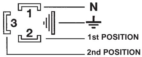
1 - Neuter
2 - Phase
3 - 2^nd flame thermostat
4/5 - Micro switcher For 2^nd flame valve
TC -KESSEL THERMOSTAT
LGB22/LMG25-STEURGERAT
MBZRDLE-ELEKTRAMGNETUENTIL
T2 - THERMOSTAT 2 STUFE
M -BRENNERMOTOR
LKS120 -STELLMOTOR
Z -FILTER
FE -IONISATION ELECTRODE
PA -AIR PRESSURE SWITCH
TA -IGNITION TRASFORMER
TS -SAFETY THERMOSTAT
TC -BOILER THERMOSTAT
LGB22/LMG25-CONTROL B0X
MBZRDLE- SOLENOID VALUE
T2-2 STAGE THERMOSTAT
M -FAN MOTOR
LKS120 -AIR SERVOMOTOR
Z -FILTER
P1 -HOUR METER
UPS584-VALUE TIGHTNESS CONTROL
CORRENTE IONIZZAZIONE MINIMA 7 yA
COURANT D'IONISATION MINIMUM 7 μA
MINIMUM IONISATION CURRENT 7μA
MINIMALIONISATIONSSTROM 7 μA
T2 - 2nd stage thermostat
P1 - Hour meter
TC - Boiler thermostat
LKS128 - Servomotor
TS - Limit thermostat
H0 - Lock-out lamp
H1 - Operating lamp
H2 - 2nd stage lamp
TA - Ignition transformer
MBZRDLE-Solenoid valve
FE - Ionisation probe
PG - Gas pressure switch
PA - Air pressure switch
LGB22/LMG25 - Control box
M - Mateur
T2 - Thermostat de 2eme etage
P1 - Compteur hora
TC - Aquastat de reglage
LGB22/LMG25 - Appareillage
气
aannnnnne aannnnnne
rrnnnne nnnnne nnnnne nnnnne nnnnne nnnnne nnnnne
Prrnnnne nnnnne
nnnnnne nnnnnnne nnnnnnne
Technical data in this brochure are given as information only. Baltur reserves the right to change specification, without notice.
For any information about our service centers telephone:

BALTUR S.p.A.