D 11 A - Active speaker DYNACORD - Free user manual and instructions
Find the device manual for free D 11 A DYNACORD in PDF.
| Product Type | Active 2-way, bi-amplified loudspeaker |
| Brand | DYNACORD |
| Model | D 11 A |
| Dimensions (W x H x D) | 429.5 x 586 x 320.5 mm |
| Net Weight | 15.3 kg |
| Power Supply | 220-240 V AC / 100-120 V AC (depending on version) |
| Max Amplifier Power | 800 W |
| Frequency Response | 48 Hz - 20 kHz |
| Coverage Angle | 80° x 40° |
| Crossover Frequency | 1.2 kHz |
| Transducers | LF: LFT3508, HF: DH 3 |
| Low-cut Filter | Switchable at 120 Hz, 12 dB/Oct |
| Enclosure Material | Robust Polypropylene |
| Grille | Powder-coated steel, acoustic foam |
| Handle | 1 integrated handle |
| Warranty | 36 months |
| Inputs | MIC (XLR), LINE (XLR/Jack), AUX (RCA) |
| Outputs | LINE THRU (XLR), MASTER OUT (XLR) |
| Cleaning | Clean only with a dry cloth |
| Safety | Do not expose to water or moisture; maintenance by qualified personnel |
| Main Spare Parts | Mains cord (5 m), LF and HF transducers |
| Optional Accessories | Cover SH-D12, mounting kit MB 112, rotary kit RMA, etc. |
Frequently Asked Questions - D 11 A DYNACORD
User questions about D 11 A DYNACORD
0 question about this device. Answer the ones you know or ask your own.
Ask a new question about this device
Download the instructions for your Active speaker in PDF format for free! Find your manual D 11 A - DYNACORD and take your electronic device back in hand. On this page are published all the documents necessary for the use of your device. D 11 A by DYNACORD.
USER MANUAL D 11 A DYNACORD
Scope of Delivery, Unpacking and Inspection 4
Warranty 4
INSTALLATION 5
Controls, Indicators and Connections 5
Cabling 7
Cooling 8
Quick Start 8
Rigging 9
SPECIFICATIONS 26
Block Diagram 27
Frequency Response 27
Beamwidth 27
Directivity 28
Dimensions 29
Setup Example 30
INHALT
EINFUHRUNG 12
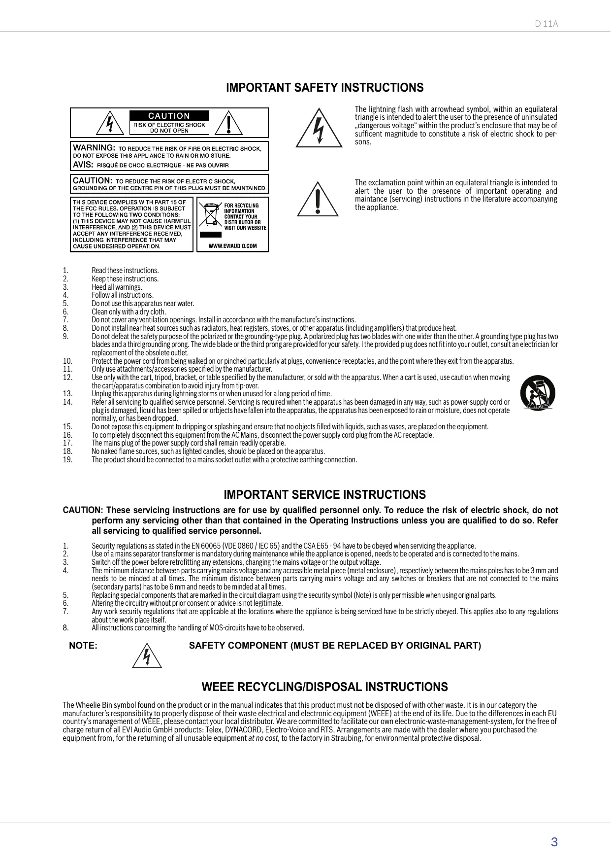
IMPORTANT SAFETY INSTRUCTIONS
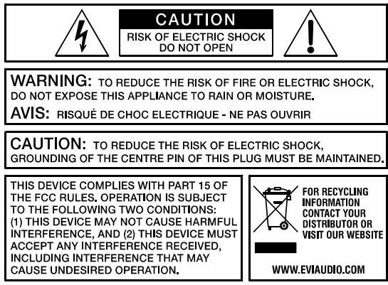
The lightning flash with arrowhead symbol, within an equilateral triangle is intended to alert the user to the presence of uninsulated "dangerous voltage" within the product's enclosure that may be of sufficient magnitude to constitute a risk of electric shock to persons.

The exclamation point within an equilateral triangle is intended to alert the user to the presence of important operating and maintenance (servicing) instructions in the literature accompanying the appliance.
- Read these instructions.
- Keep these instructions.
- Heed all warnings.
- Follow all instructions.
- Do not use this apparatus near water.
- Clean only with a dry cloth.
- Do not cover any ventilation openings. Install in accordance with the manufacture's instructions.
- Do not install near heat sources such as radiators, heat registers, stoves, or other apparatus (including amplifiers) that produce heat.
- Do not defeat the safety purpose of the polarized or the grounding-type plug. A polarized plug has two blades with one wider than the other. A grounding type plug has two blades and a third grounding prong. The wide blade or the third prong are provided for your safety. I the provided plug does not fit into your outlet, consult an electrician for replacement of the obsolete outlet.
- Protect the power cord from being walked on or pinched particularly at plugs, convenience receptacles, and the point where they exit from the apparatus.
- Only use attachments/accessories specified by the manufacturer.
- Use only with the cart, tripod, bracket, or table specified by the manufacturer, or sold with the apparatus. When a cart is used, use caution when moving the cart/apparatus combination to avoid injury from tip-over.
- Unplug this apparatus during lightning storms or when unused for a long period of time.
- Refer all servicing to qualified service personnel. Servicing is required when the apparatus has been damaged in any way, such as power-supply cord or plug is damaged, liquid has been spilled or objects have fallen into the apparatus, the apparatus has been exposed to rain or moisture, does not operate normally, or has been dropped.
- Do not expose this equipment to dripping or splashing and ensure that no objects filled with liquids, such as vases, are placed on the equipment.
- To completely disconnect this equipment from the AC Mains, disconnect the power supply cord plug from the AC receptacle.
- The mains plug of the power supply cord shall remain readily operable.
- No naked flame sources, such as lighted candles, should be placed on the apparatus.
- The product should be connected to a mains socket outlet with a protective earthing connection.

IMPORTANT SERVICE INSTRUCTIONS
CAUTION: These servicing instructions are for use by qualified personnel only. To reduce the risk of electric shock, do not perform any servicing other than that contained in the Operating Instructions unless you are qualified to do so. Refer all servicing to qualified service personnel.
- Security regulations as stated in the EN 60065 (VDE 0860 / IEC 65) and the CSA E65 - 94 have to be obeyed when servicing the appliance.
- Use of a mains separator transformer is mandatory during maintenance while the appliance is opened, needs to be operated and is connected to the mains.
- Switch off the power before retrofitting any extensions, changing the mains voltage or the output voltage.
The minimum distance between parts carrying mains voltage and any accessible metal piece (metal enclosure), respectively between the mains poles has to be 3mm and needs to be minded at all times. The minimum distance between parts carrying mains voltage and any switches or breakers that are not connected to the mains (secondary parts) has to be 6mm and needs to be minded at all times. - Replacing special components that are marked in the circuit diagram using the security symbol (Note) is only permissible when using original parts.
- Altering the circuitry without prior consent or advice is not legitimate.
- Any work security regulations that are applicable at the locations where the appliance is being serviced have to be strictly obeyed. This applies also to any regulations about the work place itself.
- All instructions concerning the handling of MOS-circuits have to be observed.
NOTE:

SAFETY COMPONENT (MUST BE REPLACED BY ORIGINAL PART)
WEEE RECYCLING/DISPOSAL INSTRUCTIONS
The Wheelie Bin symbol found on the product or in the manual indicates that this product must not be disposed of with other waste. It is in our category the manufacturer's responsibility to properly dispose of their waste electrical and electronic equipment (WEEE) at the end of its life. Due to the differences in each EU country's management of WEEE, please contact your local distributor. We are committed to facilitate our own electronic-waste-management-system, for the free of charge return of all EVI Audio GmbH products: Telex, DYNACORD, Electro-Voice and RTS. Arrangements are made with the dealer where you purchased the equipment from, for the returning of all unusable equipment at no cost, to the factory in Straubing, for environmental protective disposal.
1 Introduction
The DYNACORD D 11A is a powered, biamped, light-weight and extremely robust high-performance professional 12” 2-way fullrange plastic cabinet for use in professional sound reinforcement applications. With a variety of suspension accessories and conservative cosmetics, the D 11A is also ideally suited to be used in demanding fixed installations. The cabinet is manufactured from Polypropylene and therefore is extremely resistant against abuse on the road. For low frequencies a LFT3508 is used. The Electro-Voice DH 3 driver is used for the projection of mid and high frequencies. The Constant-Directivity HF horn has been integrated into the baffle by CAD methods. Nominal coverage angle of the cabinet is 80^ × 40^ , horizontal × vertical respectively.
The built-in digital power amplifiers are working in bi-amped operation and are controlled by an electronic x-over circuit that has been designed to optimally match the transducers' acoustic characteristics. The D 11A is ideally suited for applications as full-range cabinet or as Mid-Hic cabinet in high-performance satellite systems. EASE and Ulysses data allow fast and precise simulations.
The multitude of connection and setting facilities (MIC, LINE, AUX) allows using the D 11A in many creative ways. The master signal can be daisy-chained to a second D 11A cabinet via a regular XLR microphone cable. The built-in level control VOLUME allows easy adjustment of the required sound pressure level.
The D 11A is connected to the mains via a locked IEC inlet that guarantees a hassle-free operation. Extremely durable acoustic foam mounted to a strong powder-coated steel grille protects the loudspeaker components against any mechanical damage. A protective cover is available as an option. The trapezoidally shaped enclosure also allows employing the cabinet in monitoring applications that require extended low-frequency response compared to regular monitor speakers. A stable, integrated carrying handle and the integrated stand socket for pole-mount stands allow easy transportation and setup.
1.1 Scope of Delivery, Unpacking and Inspection
1 Active Cabinet
1 Owner's Manual (this document)
1 Mains Cord (lockable, 5 meters)
- 1 Warranty Certificate including Safety Instructions
Carefully open the packaging and take out the cabinet. Inspect the cabinet's enclosure for damages that might have occurred during transportation. Each cabinet is examined and tested in detail before leaving the manufacturing site to ensure that it arrives in perfect condition at your place. Please inform the transport company immediately if the cabinet shows any damage. Being the addressee, you are the only person who can claim damages in transit. Keep the cardboard box and all packaging materials for inspection by the transport company.
Keeping the cardboard box including all packing materials is also recommended, if the cabinet shows no external damages.
CAUTION: Do not ship the cabinet in any other than its original packaging.
When shipping the cabinet make sure to always use its original box and packaging materials. Packing the cabinet like it was packed by the manufacturer guarantees optimum protection from transport damage.
1.2 Warranty
Visit www.dynacord.com for warranty information.
WARNING:
THIS LOUDSPEAKER SYSTEM CAN PERMANENTLY DAMAGE HEARING! USE EXTREME CARE WHEN SETTING SOUND PRESSURE LEVELS!
HINT: This equipment has been tested and found to comply with the limits for a Class A digital device, pursuant to Part 15 of the FCC Rules. These limits are designed to provide reasonable protection against harmful interference when the equipment is operated in a commercial environment. This equipment generates, uses, and can radiate radio frequency energy and, if not installed and used in accordance with the instruction manual, may cause harmful interference to radio communications. Operation of this equipment in a residential area is likely to cause harmful interference in which case the user will be required to correct the interference at his own expense.
NOTES: This equipment has been tested and found to comply pursuant to the product family standard for audio professional use according EMC Directive 2004/108/EC: EN55103-1 and EN55013-2 standards (with the limits for E4 and E5 electromagnetic environment); EN61000-3-2, EN61000-3-3.
2 Installation
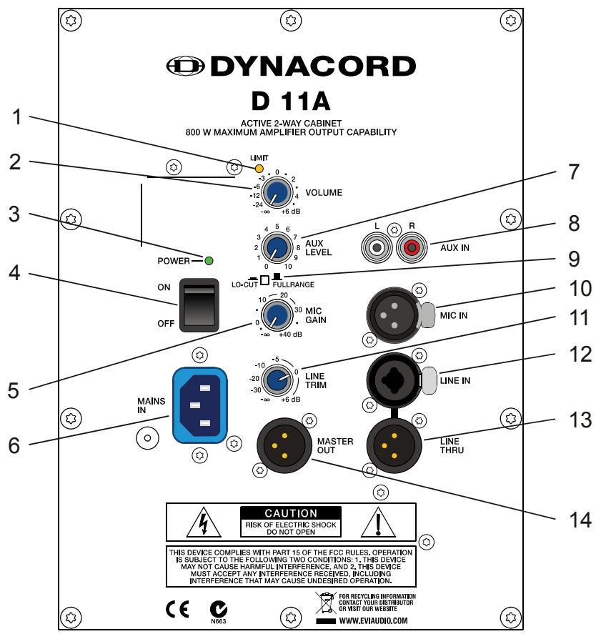
2.1 Controls, Indicators and Connections
| Number | Description |
| 1 | Limit indicator (LIMIT) |
| 2 | Master level control (VOLUME) |
| 3 | Power on/off indicator (POWER) |
| 4 | Mains switch (ON / OFF) |
| 5 | Microphone level control (MIC GAIN) |
| 6 | Mains connector, lockable (MAINS IN) |
| 7 | Aux level control (AUX LEVEL) |
| 8 | Input connector (RCA) for stereo aux signal (AUX IN L/R) |
| 9 | Mode selection switch (LO-CUT / FULLRANGE) |
| 10 | Input connector for microphone level audio signal (MIC IN) |
| 11 | Line level control (LINE TRIM) |
| 12 | Input connector (XLR or phone) for line level audio signal (LINE IN) |
| 13 | Output connector (XLR) for line level audio signal (LINE THRU) |
| 14 | Output connector (XLR) for master audio signal (MASTER OUT) |
1 LIMIT INDICATOR (LIMIT)
Limit Brief blinking of the LIMIT LED indicates that the power amplifier of the D 11A is operated at its limits. Short-term blinking is uncritical, because the integrated limiter compensates minor distortion. Constant lighting of the LED indicates that the sound is negatively affected. Reducing the output volume is strongly recommended.
2 MASTER LEVEL CONTROL (VOLUME)
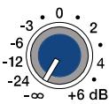
VOLUME
Level control for adjusting the power amp's overall amplification.
3 POWER ON/OFF INDICATOR (POWER)
POWER—
The POWER LED lights green if the mains switch is ON and the mains cord is connect-
ed correctly.
4 MAINS SWITCH (ON/OFF)
ON
OFF

Mains switch for switching the unit's power ON or OFF. The POWER LED lights after turning the power ON. Make sure that the mains cord is correctly connected if the LED is not lit upon switching the power on. If the mains cord is correctly connected,
mains voltage is present and the LED does not light upon power-on, please contact your local dealer.
Level control for adjusting the amplification of the signal at the MIC IN input.
6 MAINS CONNECTOR, LOCKABLE (MAINS IN)
MAINS IN
The D 11A receives its power supply via the lockable MAINS IN connector. Only the provided power cord may be used. Connect the D 11A only to a mains network, which corresponds to the requirements indicated on the type plate. Press the yellow button at the plug to disconnect the power
cord.
CAUTION: This appliance has no user-servicable parts inside. Leave any servicing and maintenance to qualified service technicians only.
7 AUX LEVEL CONTROL (AUX LEVEL)
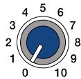
AUX LEVEL
This control is used to adjust the input level of the signal source that is connected to AUX IN L / R input.
8 INPUT CONNECTOR FOR STEREO AUX SIGNAL (AUX IN L / R)
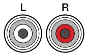
AUX IN
These RCA-type connectors allow the connection of stereo signal sources (e.g. CD-Player). The stereo input signals are internally summed for monaural output.
CAUTION: Before connecting or unplugging an appliance, make sure to turn the AUX LEVEL control all the way down (counterclockwise).
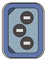
9 MODE SELECTION SWITCH (LO-CUT/FULLRANGE)
If the D 11A is used as a fullrange system, select FULLRANGE (button not pressed). If a subwoofer is available, select LO-CUT (button pressed) for activating the internal low-cut filter. The setting LO-CUT can also be used for monitor or delay applications, when a high bass level is not necessary.
10 INPUT CONNECTOR FOR MICROPHONE AUDIO SIGNAL (MIC IN)
MIC IN
MIC IN is an electronically balanced XLR-type input for connecting low-impedance microphones.
CAUTION: Before making any connections or disconnections, make sure to set the MIC GAIN level control to the counterclockwise stop. Extremely high volume settings may result in unpleasing feedback noise.
Level control for adjusting the amplification of the signal at the LINE IN input.
12 INPUT CONNECTOR FOR AUDIO SIGNAL (LINE IN)
LINE IN
LINE IN is an electronically balanced input for connecting high-impedance audio signal sources like mixers, electronic music instruments like keyboards, guitars and bass guitars with built-in active electronics. It is possible to
connect balanced as well as unbalanced gear at the LINE IN input using an monaural or stereo phone plug cable or XLR-type plug cable. Balanced connection is preferable whenever the source unit has a balanced output stage. Following this advice will provide you with the advantage of less interference that is introduced from external hum or HF-induction.
CAUTION: Before making any connections or disconnections, make sure to set the level control to the counterclockwise stop.
13 OUTPUT CONNECTOR FOR AUDIO SIGNAL (LINE THRU)

LINE THRU
This electronically balanced output provides the carried through audio signal from the LINE IN connector. It can be used to feed additional external equipment (e.g. an additional D 11A) with the identical input signal.
14 OUTPUT CONNECTOR (MASTER OUT)

MASTER OUT
The output connector provides the Master Signal (Line+Mic+Aux) for "carrying through" the input signal. The level of the output signal is independent of the setting of the Master level control ("Pre Fader").
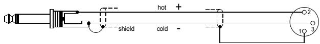
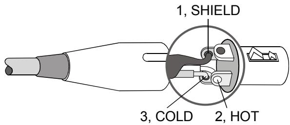
2.2 Cabling
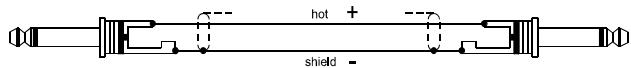
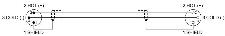
For connecting audio signal sources to the D 11A, we recommend using cable with balanced XLR-type or stereo phone plug connectors. Using balanced cable reduces the risk of sound degradation resulting from interference. However, make sure to mind the pin-assignment as shown below. Original DYNACORD cable from our accessory program will always comply with this pin-assignment.
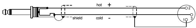
Illustration 2-1: Balanced and unbalanced phone plug
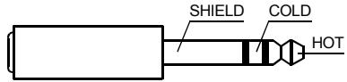
BALANCED
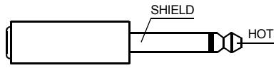
UNBALANCED
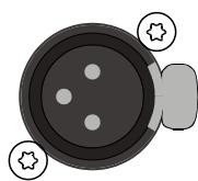
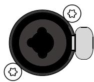
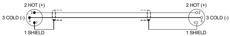
Illustration 2-2: Balanced XLR male
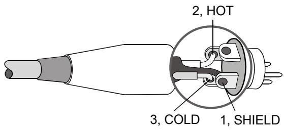
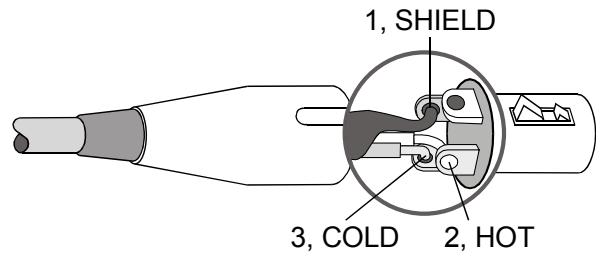
Illustration 2-3: Balanced XLR female
Cable
Application
balanced connection of microphones

Cable connection phone to XLR-type, unbalanced
unbalanced external equipment with XLR-type in/output jacks
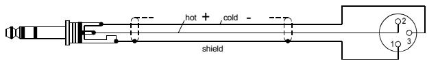
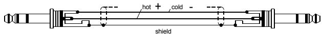
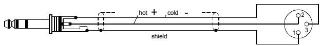
Cable connection phone to XLR-type, balanced
balanced external equipment with XLR-type in/output jacks
unbalanced external equipment with phone jack in/output jacks
Standard phone-type, balanced
balanced external equipment with phone jack in/output jacks
2.3 Cooling
This is a powered speaker with a very high efficient amplifier module and as a result does not get really hot. The temperature of the amplifier module is monitored. In the rare event it does get too hot it will automatically shut down to protect itself. Once its temperature has returned to within its operating range the amp will turn back on.
This may happen when the speaker is operated in very high ambient temperatures and the enclosure is exposed to direct sunlight. Always ensure adequate cooling and appropriate shade to keep the ambient temperature around the product within the specified operating temperature range.
2.4 Quick Start
CAUTION: After installing the system, first switch on the mixing console and position the mixer's master faders to their minimum settings. That followed, switch on the D 11A and use the master faders to adjust the desired volume setting. Otherwise, high sound levels caused by unintentional playback of a program source could be the result, which might cause hearing damage.
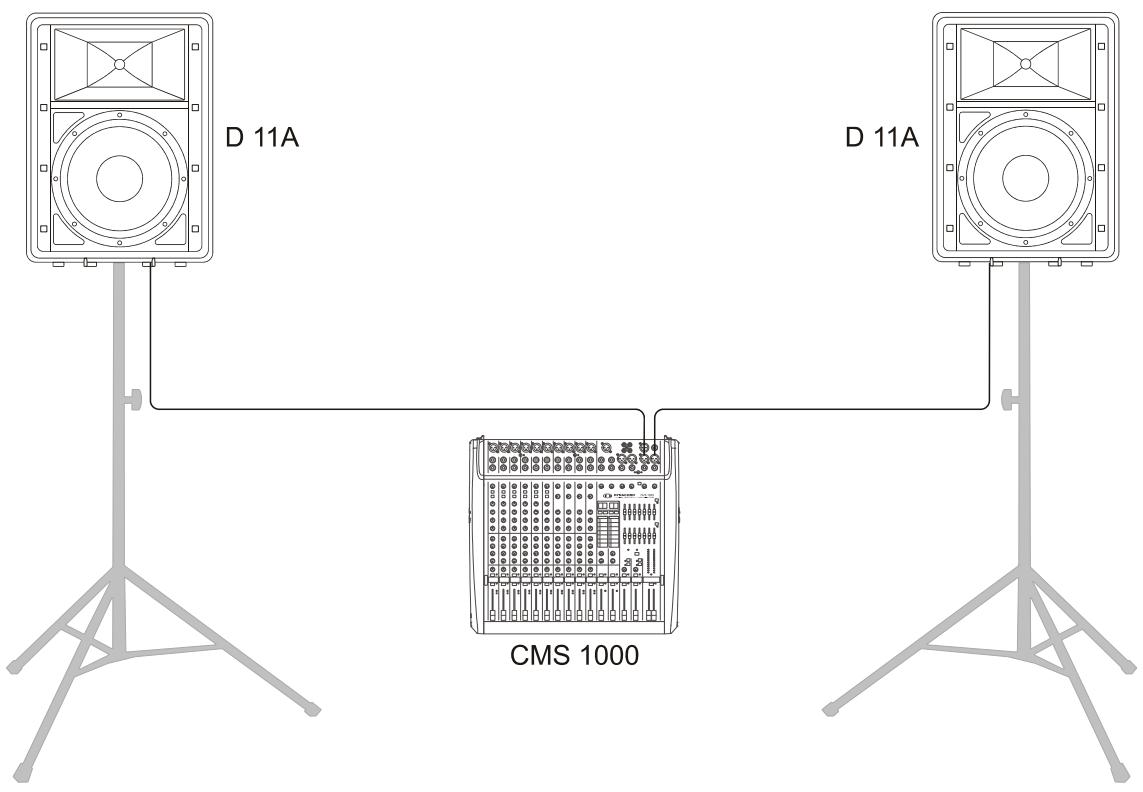
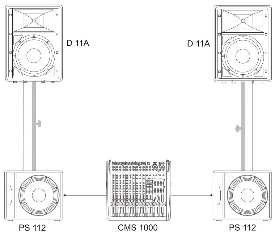
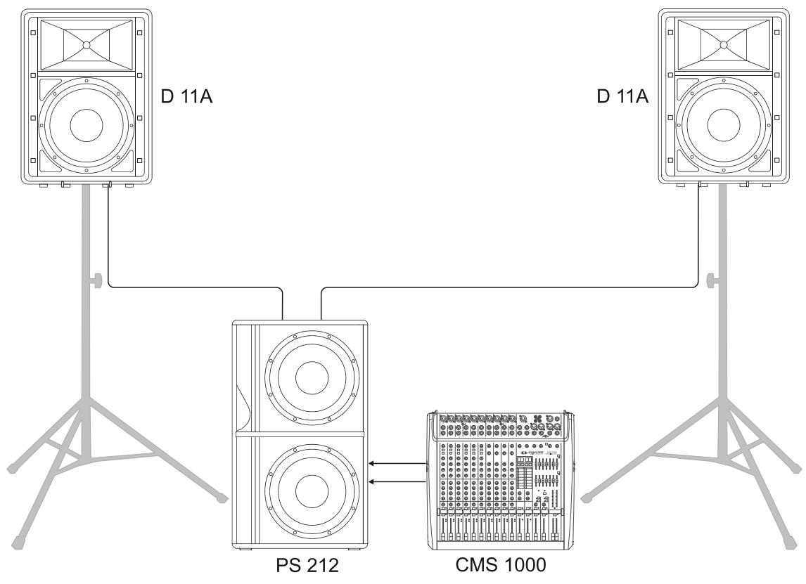
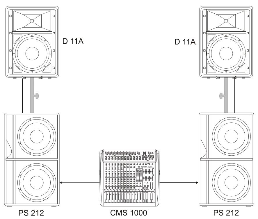
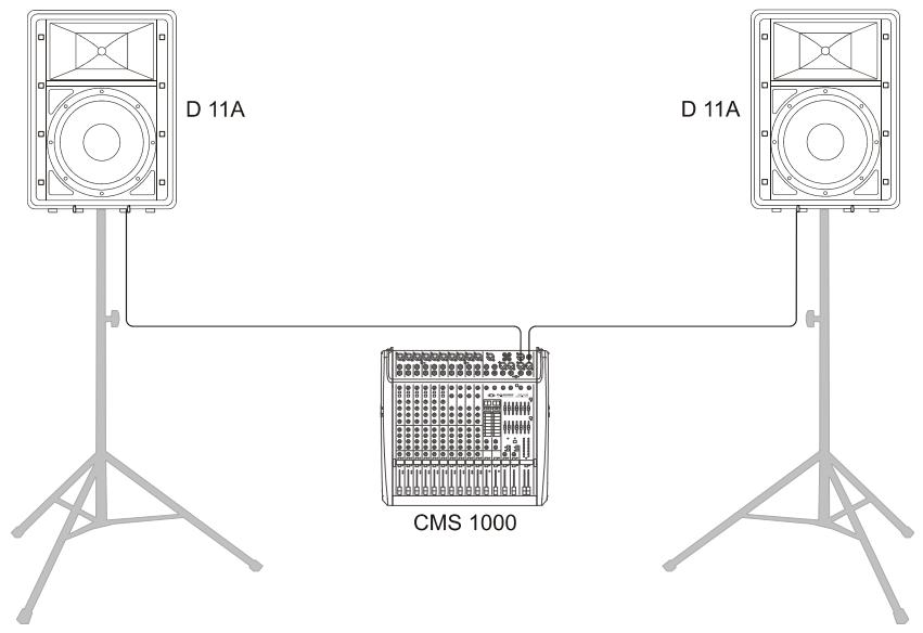
This Quick Start Manual outlines setup and operation of the D 11A connected to a DYNACORD CMS mixer.
- Place the D 11A, mounted on pole-mount stands to the left and to the right. The lower edges of the speaker systems should be approximately 1,8 meters above the audience to provide sufficient coverage and to prevent that listeners nearby are subject to extreme sound levels.
- Using suitable XLR-type cables connect the Master Outputs of your mixing console, e.g. DYNACORD CMS 1000, to LINE IN of the D 11A. Position the master faders on the mixer to their minimum setting. Now, switch on the mixer.
- Connect the D 11A to the mains outlet using the supplied mains cord. Plug the connector into the MAINS IN socket. Use the Mains switch to power-up the D 11A.
- Set the level controls VOLUME and LINE TRIM of the D 11A to 0dB.
- Connect an audio source, e.g. CD player, to a line
level input of the mixer, e.g. CMS 1000. Set all rotary controls of the mixing console input channel to their center position. Adjust the input channel's 'Gain' control so that the Peak LED should not light at all or blink only once in a while.
- Slowly raise channel fader and master faders on the mixing console to the desired positions - i.e. volume settings.
- Your system is now ready for operation. Individual sound adjustments necessary can be made using the controls of the mixer's corresponding input channels.
- Now, have fun with your D 11A system!
- After use, first switch off the D 11A and then the mixing console, so that distracting power-off noise will not occur. When using a DYNACORD CMS mixer, no power-off noise will be output from the 'Master Outputs'. This allows switching off the mixer first without a problem.
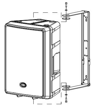
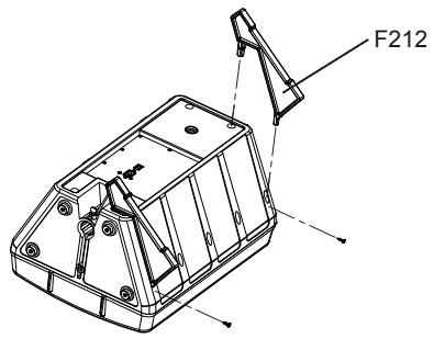
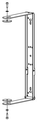
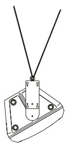
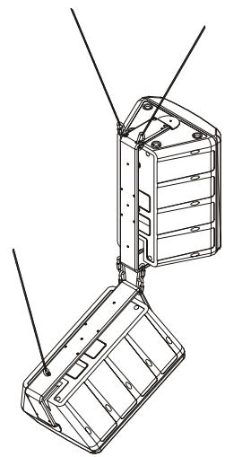
2.5 Rigging
CAUTION: We expressly point out that the relevant safety regulations must be observed for "flying" loudspeaker systems. It is imperative that qualified expert advice is sought.
CAUTION: Suspend any object is potentially dangerous and should only be attempted by individuals who have a thorough knowledge of the techniques and regulations of rigging objects overhead. DYNACORD strongly recommends that D 11A speakers be suspended taking into account all current national, federal, state and local regulations. It is the responsibility of the installer to ensure that D 11A speakers are safely installed in accordance with all such regulations. If D 11A speakers are suspended, DYNA-CORD strongly recommends that the system be inspected at least once a year. If any sign of weakness or damage is detected, remedial action should be taken immediately.
Order No. see Specifications (page 26)
MB-200UMH
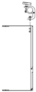
MB-200UMH +TC-02
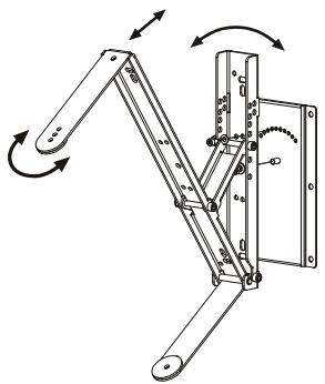
MB-200 UMH +RMA+TMA
MB112
| Property | D 11A 230 Volt | D 11A 120 Volt |
| Order No. | F01U135396 (D113301) | F01U135397 (D113302) |
| Cabinet | Powered Full-Range 2-Way | |
| Maximum Amplifier Output Capability | 800 Watts | |
| Lo Amplifier Power RMS | 200 Watts | |
| Mid-High Amplifier Power RMS | 200 Watts | |
| Max. SPL 1 m/calc | 126 dB | |
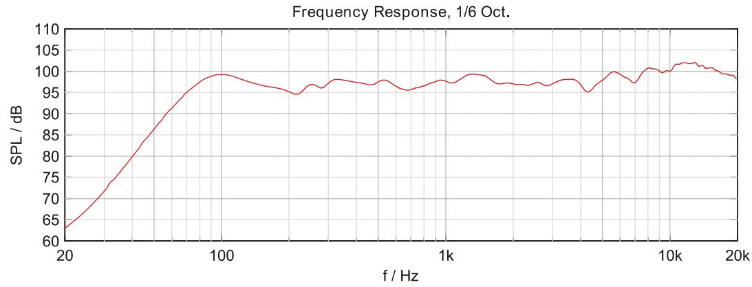
| Frequency Range (-10 dB) | 48 Hz to 20 kHz | |
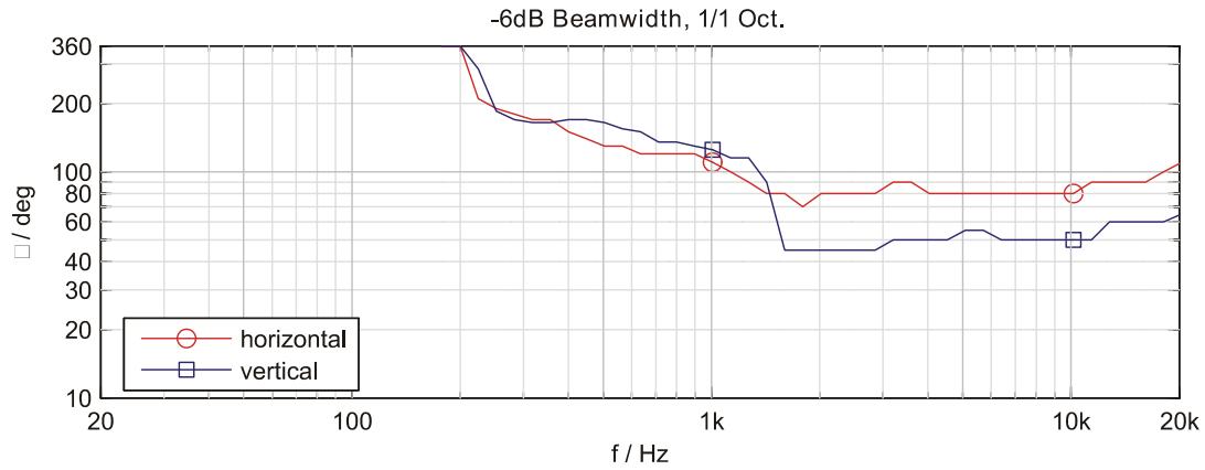
| Nominal Coverage Angle (Horizontal x Vertical) | 80° x 40° | |
| X-Over Frequency | 1.2 kHz | |
| LF Transducer | LFT3508 | |
| HF Transducer | DH 3 | |
| Switchable Lo-Cut | 120 Hz, 12 dB/Oct | |
| Power Requirement | 220 to 240 V AC, 0.6 A, 50 to 60 Hz | 100 to 120 V AC, 1.1 A, 50 to 60 Hz |
| Operating Temperature Range | 0 °C to 40 °C | |
| Dimensions (W x H x D) | 429.5 mm x 586 mm x 320.5 mm (16.90" x 23.07" x 12.55") | |
| Net Weight | 15.3 kg | |
| Shipping Weight | 18.3 kg | |
| Enclosure material | Heavy Duty Polypropylene | |
| Finish | Black | |
| Grille | Powder coated steel, Acoustic foam | |
| Handles | 1 | |
| Warranty | 36 months | |
| Optional Accessories | ||
| SH-D12 Dust Cover | F01U118994 (D113046) | |
| F 212 Monitor feet | F01U100802 (D113040) | |
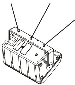
| MB 112 Eyebolt-Set M8 1) | F01U100803 (D113041) | |
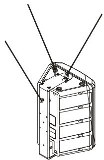
| MB 212 U-Mounting Bracket | F01U100804 (D113042) | |
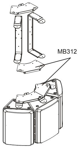
| MB 312 Horizontal Cluster Plate | F01U100805 (D113043) | |
| MB 200 UMH U-Bracket | F01U120157 (D170183) | |
| TMA Tilt angle for UMH | F01U118977 (D112815) | |
| RMA Rotatable Mounting Kit | F01U118976 (D112807) | |
| TC-02 Truss clamp | F01U100657 (D112808) | |
| Spare Parts | ||
| Mains Cord (5 meters) | F01U108377 (D368217) | F01U105973 (D362222) |
| LF Transducer | F01U107290 (D366023) | |
| HF Transducer | F01U103119 (D353078) | |
1) MB 112 must only be used together with MB 212 due to safety reasons.
SAFETY COMPONENT (MUST BE REPLACED BY ORIGINAL PART)
Cable connection phone to XLR-type, unbalanced
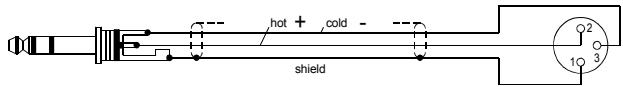
Cable connection phone to XLR-type, balanced
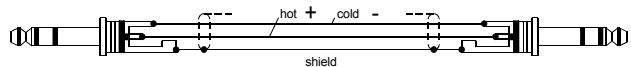
Standard phone-type, balanced
1) MB 112 must only be used together with MB 212 due to safety reasons.
IMPORTANT INFORMATIONS DE SECURITÉ
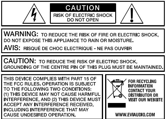
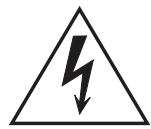

Illustration 2-2: Cables audio symétrisés (XLR, male,
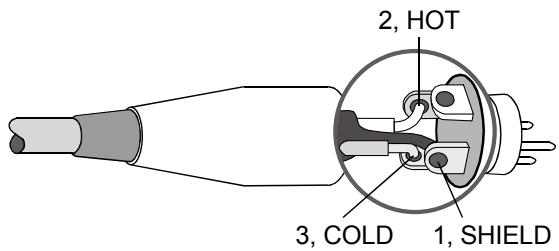
Illustration 2-3: Câbles audio symétrisés (XLR, female)
Cable
Application
Cable connection phone to XLR-type, unbalanced
Cable connection phone to XLR-type, balanced
1) MB 112 must only be used together with MB 212 due to safety reasons.
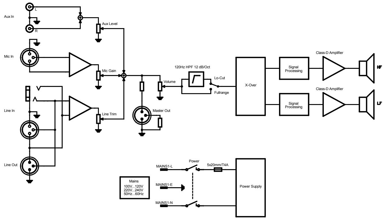
3.1 Block Diagram
3.2 Frequency Response
3.3 Beamwidth
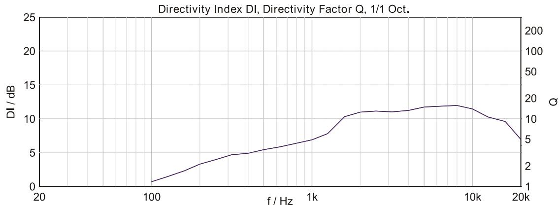
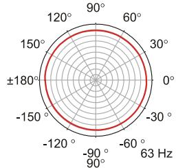
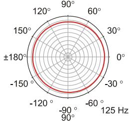
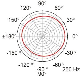
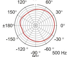
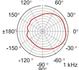
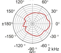
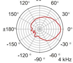
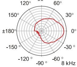
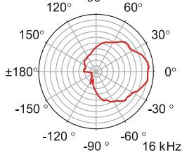
3.4 Directivity
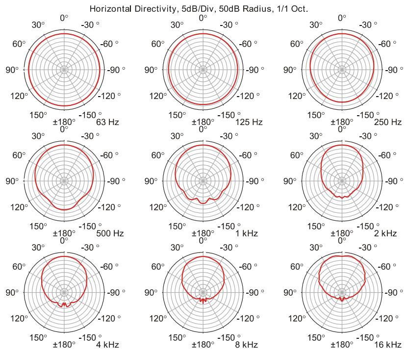
HORIZONTAL DIRECTIVITY
VERTICAL DIRECTIVITY
Vertical Directivity, 5dB/Div, 50dB Radius, 1/1 Oct.
3.5 Dimensions
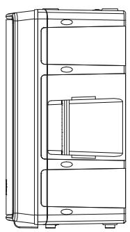
SIDE RIGHT
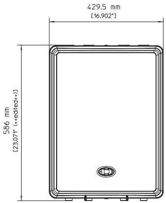
FRONT
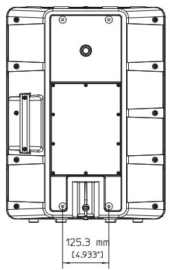
REAR
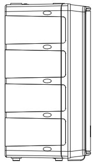
SIDE LEFT
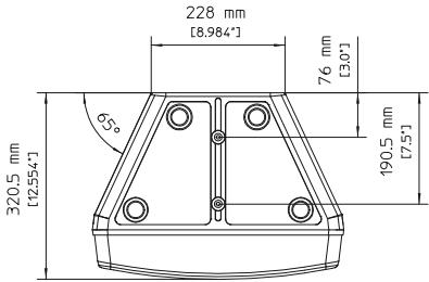
TOP
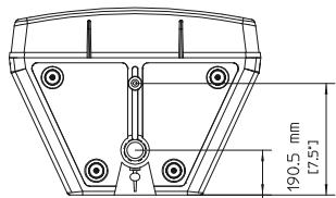
BOTTOM
76 mm
3.6 Setup Example