
Air 3500 - Headphones DYNACORD - Free user manual and instructions
Find the device manual for free Air 3500 DYNACORD in PDF.

| Brand | Dynacord |
| Model | Air 3500 |
| Product Type | Over-ear, closed-back headphones |
| Driver Size | 40 mm |
| Frequency Response | 20 Hz - 20 kHz |
| Impedance | 32 ohms |
| Sensitivity | 100 dB/mW |
| Maximum Input Power | 100 mW |
| Cable Length | 3 m |
| Connector | 3.5 mm (1/8") with 1/4" adapter |
| Weight | 250 g |
| Dimensions (WxHxD) | 200 x 180 x 80 mm |
| Color | Black |
| Material | Plastic, leatherette earpads |
| Noise Reduction | Passive ambient noise reduction |
| Foldable | Yes |
| Usage | Studio monitoring, live sound, personal listening |
| Accessories Included | 1/4" adapter, carrying bag |
| Cleaning | Wipe with a dry or slightly damp cloth; avoid liquids entering the ear cups |
| Repair | Contact authorized Dynacord service center for spare parts and repairs |
| Safety | Do not listen at high volumes for extended periods to prevent hearing damage |
Frequently Asked Questions - Air 3500 DYNACORD
User questions about Air 3500 DYNACORD
0 question about this device. Answer the ones you know or ask your own.
Ask a new question about this device
Download the instructions for your Headphones in PDF format for free! Find your manual Air 3500 - DYNACORD and take your electronic device back in hand. On this page are published all the documents necessary for the use of your device. Air 3500 by DYNACORD.
USER MANUAL Air 3500 DYNACORD
natural_image
Front view of a black and white headboard with adjustable straps and earplugs (no text or symbols visible)Air 3500
Noise Reduction Headset
Air 3500 Noise Reduction Headset
PROPRIETARY NOTICE
The product information and design disclosed herein were originated by and are the property of Bosch Security Systems, Inc. Bosch reserves all patent, proprietary design, manufacturing, reproduction, use and sales rights thereto, and to any article disclosed therein, except to the extent rights are expressly granted to others.
COPYRIGHT NOTICE
Copyright 2023 by Bosch Security Systems, L.L.C. All rights reserved. Reproduction, in whole or in part, without prior written permission from Bosch is prohibited.
PURPOSE OF MANUAL
This manual contains information for the overhaul and servicing of the AIR3500 headset.
TECHNICAL SUPPORT
A liaison between the customer and factory is provided by the Bosch Product Support Department. Consultation and assistance on technical problems, part information, and availability of local and factory repair facilities is available. When writing, include all information concerning problem and email:
Bosch Security Systems, LLC
Email: telexdispatchtechsupport@us.bosch.com
Attn: Aircraft Product Support Mgr Telephone: 877-863-4188
PARTS ORDERING
Replacement parts may be ordered from our parts department. When ordering, please include the following information.
- Model Number
- Part Description
• Part Number
• Quantity
Bosch Security Systems, LLC
Attn: Parts Department
Telephone: 800-553-5992
Fax: 402-467-3279
E-mail: repair@us.bosch.com
REPAIRS
In order to maintain the FAA certification, all repairs to the headset must be made only by persons authorized under Part 43 of the Federal Aviation Agency regulations. Bosch offers full support and repair.
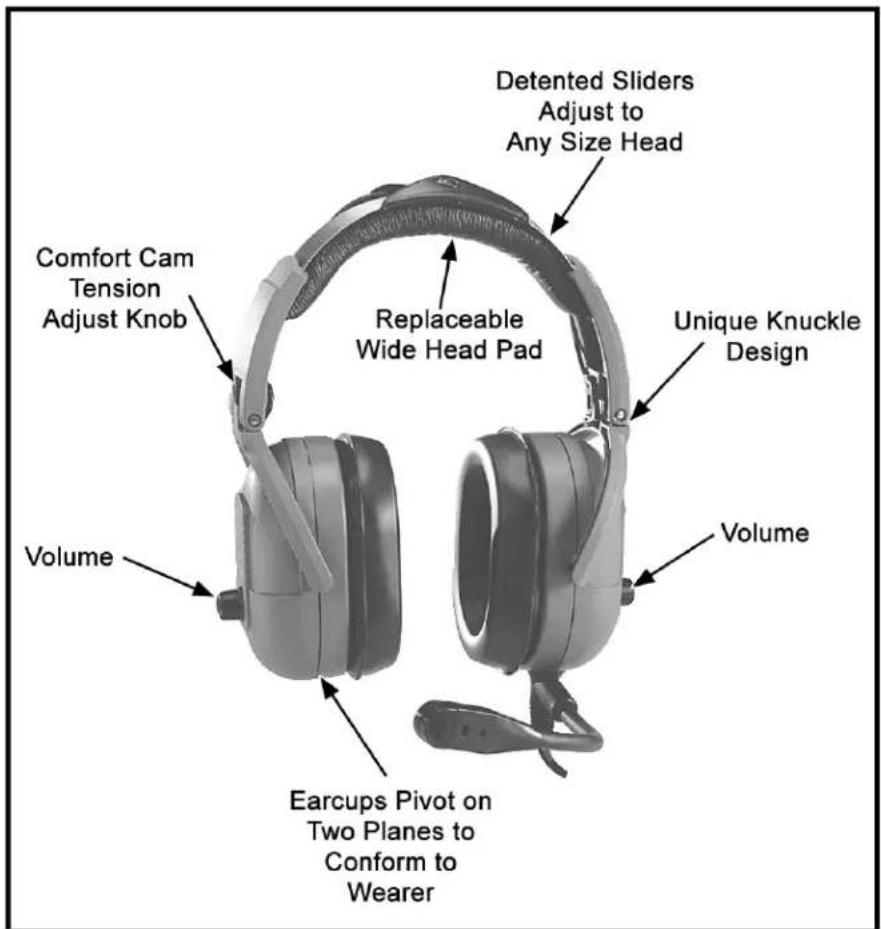
FIGURE 1. Air 3500 Noise Reduction Headset
Table
of
Contents
Headband Size Adjustment ....3
Headband Pressure Adjustment ....4
Left or Right Side Microphone Placement 4
Permanently Changing Microphone Side ....5
Connection 5
Stereo Mono Switch (fixed-wing version only) 7
Volume Adjustment ....7
Microphone Gain Adjustment 7
Ear Cushion Replacement 7
Head Pad Replacement 8
Mic Element Removal 8
Specifications 9
Exploded View Parts List 10
Headband Size Adjustment
To adjust the headband size, do the following:
Move the earcup sliders up or down on the headband.
Size is properly adjusted when the earcups are centered over the ears.
IMPORTANT: It is important to adjust both sides of the headband the same to keep the headband and pad properly centered over the head.

natural_image
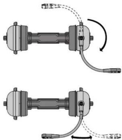
Mechanical assembly diagram showing a curved bracket with directional arrows indicating motion (no text or symbols)FIGURE 1. Headband Size Adjustment
Headband Pressure Adjustment
There are three (3) pressure settings. Increasing the pressure improves the seal between the carcup and the head for greater noise reduction.
To change the pressure setting, do the following:
- Fold the earcup in as shown in Figure 2.
- Rotate the Comfort Cam adjust knob to the desired setting.
- Repeat for the other earcup.
IMPORTANT: Both sides of the headband should be set to the same pressure setting to keep the headband properly centered on the head.

natural_image
Technical illustration of a mechanical device with lever and handle (no text or symbols)Comfort Cam™
ADJUSTMENT KNOB SETTINGS

FIGURE 2. Headband Pressure Adjustment
Left or Right Side Microphone Placement
To place the microphone, do the following:
- Rotate the boom, as shown in Figure 3.
natural_image
Mechanical assembly diagram showing two connected components with curved arrows indicating motion (no text or symbols)FIGURE 3. Rotating and Reshaping the Boom
- Reshape the boom so the microphone is at the corner of the mouth.
Permanently Changing Microphone Side
To permanently change the side of the headset the microphone is on, do the following:
- Press the release catch and carefully pull out the mic element. Avoid pulling the connecting wires.
- Turn the microphone element over and reinsert it as shown in Figure 4.

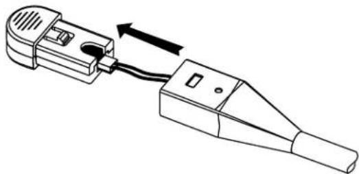
natural_image
Diagram of a mechanical clamp or connector with a cable and directional arrow indicating motion (no text or symbols)FIGURE 4. Mic Element Rotation
Connection
To connect the headset, do the following:
Using Figure 5, connect the headset to the aircraft radio or intercom system.
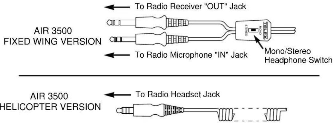
FIGURE 5. Air 3500 Connectors
Stereo Mono Switch (fixed-wing version only)
This switch is located on the y-cord (Figure 5).
To set the stereo mono switch, do the following:
Set the switch to stereo for aircraft with stereo intercom systems. OR Set the switch to mono for monaural intercom system or for direct connection to the aircraft radio.
Volume Adjustment
To adjust the volume, do the following:
When the microphone is worn on the left side, volume is increased by rotating the top of the controls clockwise. OR When the microphone is worn on the right side, volume is increased by rotating the top of the controls counter-clockwise.
IMPORTANT:
The microphone gain has been factory-adjusted to the nominal level required for FAA certification, and it should normally not require readjustment. Readjustment by a qualified avionics technician is recommended.
To access the gain trimmer, do the following:
- Insert a small flat-blade screwdriver in the mic element. (Figure 6)

FIGURE 6. Air 3500 Mic Gain Adjustment
- Rotate the trimmer clockwise to increase the gain.
Ear Cushion Replacement
To remove an old ear cushion, do the following:
Grasp the old ear cushion and pull it off the earcup.
To install a new ear cushion, do the following:
- Starting at the top of the earcup, place the flap on the back of the ear cushion over the lip along the top of the earcup.
- Pull the bottom of the ear cushion down over the lip at the bottom of the earcup.
Head Pad Replacement
To replace the head pad, do the following:
- Unsnap the old head pad.
- Pry the head pad off the headband (it is held in place with adhesive).
- Peel off the adhesive backing on the new head pad.
- Attach the new pad to the headband.
IMPORTANT: Make sure the overhead cord is inside the flaps of the head pad.
- Snap the flaps closed.
Mic Element Removal
To remove the mic element, do the following:
- Press the release catch on the microphone element.
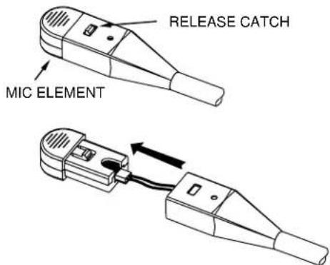
FIGURE 7. Mic Element Removal for Replacement
- Carefully pull out the element.
NOTE: Avoid pulling on the microphone wires.
- Pull the plastic connector housing to unplug the microphone element.
Receivers
Type: Dynamic
Impedance: Accepts 150-600 Ohm sources
Frequency Response: 350Hz -3.0kHz ±6dB
Sensitivity: 90 ±5dB SPL for 1mW, 1kHz input
Maximum Power Input: 30mW
Microphone/Amplifier Assembly
Microphone Type: Noise-canceling electret condenser
Output Impedance:
50 Ohms (designed for radio input impedances from 50-600 Ohms
Frequency Response: 100Hz - 3.5kHz
Sensitivity: -53 +2/-1dB (ref: 1V/μbar)
Operating Voltage: 8-16 Vdc
Cords and Plugs
Air 3500, general aviation version:
Cord: 5.5ft (1.7m) "Y" cord with stereo/mono selector switch
Receiver Plug: 1/4" stereo phone plug
Microphone Plug: PJ-068 equivalent
Air 3500HE, Helicopter version:
Cord: 5.5ft (1.7m) coiled cord
Plug: TP-120, U-93A/U, U-174/U equivalent
| Item No. Part No. Description Qty | |||
| 1 800198 | -001 Replacement Head Pad 1 | ||
| 2 19652-057 Coiled Cord (helicopter version only) 1 | |||
| 3 545015 | -000 Stereo/Mono Switch | (fixed wing-version only) | 1 |
| 4 800138 | -000 Y-cord, Complete W/Switch | (fixed-wing version only) | 1 |
| 5 590060 | -000 Cord Clip (fixed-wing version only) 1 | ||
| 6 800136 | -000 Microphone Element Assembly 1 | ||
| 7 800147 | -001 Foam Ear Pads (set of 2) 1 | ||
| 8 800027 | -002 Gel-filled Ear Pads (set of 2) 1 | ||
| 9 700498 | -000 Foam Top Cover 4 | ||
| 10 | 51856-003 Screw, Plastite, #2-56 x .5” | 4 | |
| 11 | 590055-001 Headphone Driver Assembly | 2 | |
| 12 | 700487-004 Foam Liner | 2 | |
| 13 | 700487-002 Foam Liner (non-boom side only) | 1 | |
| 14 | 700487-000 Foam Liner (boom side only) | 1 | |
| 15 | 54131-008 | Potentiometer with Nut and Lockwasher (non-boom side) | 2 |
| 16 | 54131-009 Potentiometer with Nut and Lockwasher (boom side) | 2 | |
| 17 | 580001-001 O-ring | 2 | |
| 18 | 700453-000 Tension Adjustment Knob | 2 | |
| 19 | 53435-000 Volume Knob | 2 | |
| 20 | 56517-000 Volume Knob Insert | 2 | |
| 21 | 700449-000 Wire Boot | 2 | |
| 22 | 51709-000 Tie Wrap | 2 | |
| 23 | 57012-001 Windscreen | 1 | |

FIGURE 8. Exploded View for Parts Replacement

FIGURE 9. Wiring Diagram for Fixed-Wing Version

flowchart
graph TD
    A["Microphone"] --> B["OR"]
    B --> C["OVERHEAD"]
    C --> D["ROB SideNon-Boom Side"]
    D --> E["ROB Side"]
    E --> F["300Ω/200Ω"]
    G["5K Ω"] --> H["WHT 1, 2, 3"]
    H --> I["BLK 2, 3"]
    I --> J["BRIDGE"]
    K["BLK 1, 2, 3"] --> L["WHT 5K Ω"]
    L --> M["ROB Side"]
    N["RED BLK"] --> O["ROB Side"]
    P["NC BLK"] --> Q["ROB Side"]
    R["WHT BLU"] --> S["ROB Side"]
    T["ND"] --> U["Ground"]
FIGURE 10. Wiring Diagram for Helicopter Version
Bosch Security Systems, LLC
130 Perinton Parkway
Fairport, NY 14450
USA
www.telex.com
© Bosch Security Systems, LLC, 2023
EU importer:


- Air 3500 Noise Reduction Headset
- PROPRIETARY NOTICE
- COPYRIGHT NOTICE
- PURPOSE OF MANUAL
- TECHNICAL SUPPORT
- PARTS ORDERING
- REPAIRS
- Table
- of
- Contents
- Headband Size Adjustment
- Headband Pressure Adjustment
- Left or Right Side Microphone Placement
- Permanently Changing Microphone Side
- Connection
- Stereo Mono Switch (fixed-wing version only)
- Volume Adjustment
- IMPORTANT:
- Ear Cushion Replacement
- Head Pad Replacement
- Mic Element Removal
- Receivers
- Microphone/Amplifier Assembly
- Cords and Plugs
Brand : DYNACORD
Model : Air 3500
Category : Headphones