
BORDEAUX - Fireplace insert WANDERS - Free user manual and instructions
Find the device manual for free BORDEAUX WANDERS in PDF.
| Product type | Gas insert fireplace |
| Brand | WANDERS |
| Model | BORDEAUX |
| Dimensions (H x W x D) | 552 x 404 x 312 mm |
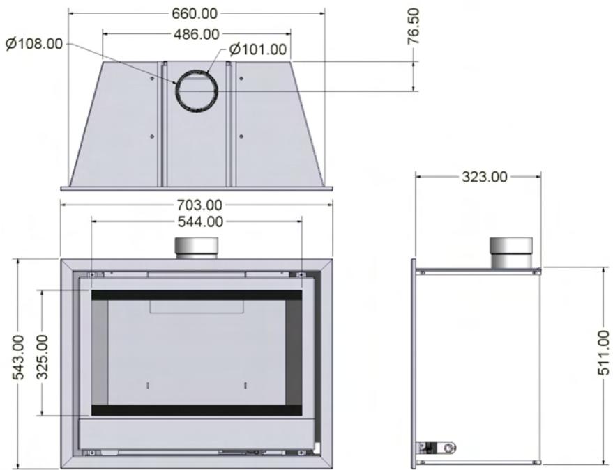
| Firebox dimensions (H x W x D) | 511 x 660 x 323 mm (recess) |
| Fuel | Natural gas (G20) – LPG not available |
| Nominal power (max) | 4.3 kW (PCI) |
| Useful power (max) | 3.5 kW |
| Efficiency | 81% |
| Gas consumption (max) | 0.445 m³/h |
| Supply pressure | 20 mbar (static) / 16 mbar (dynamic) |
| Ignition type | Piezo with pilot light |
| Control | Remote control with thermostat and timer |
| Flame adjustment | Continuous (electronic by motor) |
| Safety | TTB (thermal), automatic shutdown after 2h without signal |
| Safety distance | 1 m in front and sides (combustible materials) |
| Maintenance | Annually by approved installer |
| Glass cleaning | Special product for ceramic glass |
| Replacement parts | Ceramic logs, glass, remote control |
| Warranty | 2 years (UK) / 1 year (other countries) |
Frequently Asked Questions - BORDEAUX WANDERS
User questions about BORDEAUX WANDERS
0 question about this device. Answer the ones you know or ask your own.
Ask a new question about this device
Download the instructions for your Fireplace insert in PDF format for free! Find your manual BORDEAUX - WANDERS and take your electronic device back in hand. On this page are published all the documents necessary for the use of your device. BORDEAUX by WANDERS.
USER MANUAL BORDEAUX WANDERS
INSTALLATIE EN BEDIENINGSVOORSCHRIFTEN VOOR:
INSTALLATION AND OPERATION INSTRUCTIONS FOR:
BORDEAUX
natural_image
3D rendering of a rectangular enclosure with internal partitions and mounting holes (no text or symbols)WANDERS
www.wanders.com
NL GB
INHOUDSOPGAVE
natural_image
Interior view of a computer monitor frame with labeled components (no text or symbols on the device itself)Fig.1
natural_image
Cross-sectional diagram of a device casing with internal components and directional arrows (no text or symbols)Fig.2
natural_image
3D mechanical assembly diagram showing internal components with arrows indicating direction (no text or symbols)Fig. 3
natural_image
3D CAD model of a mechanical enclosure with internal components and a cylindrical housing (no text or symbols visible)natural_image
Interior view of a laboratory setup with a dark chamber containing a textured material and a grid of small objects, no visible text or symbols.Fig. 4a
natural_image
Exterior view of a fire safety test bench with burnt wood and gravel, no visible text or symbolsFig. 4b
natural_image
Photograph of a firewood stove burner with multiple firewood logs and scattered debris (no visible text or symbols)Fig. 4c
2.8 Afstandsbediening.
natural_image
Close-up of a mechanical testing setup with tubing and a labeled component (no readable text or symbols)Fig. 6
VOOR
MICRO
SCHAKELAAR
natural_image
Pure electrical connector diagram without any text, numbers, or symbolsSTEKKERS VOOR
MOTOR
natural_image
3D rendering of a rectangular industrial or mechanical enclosure with internal black bands and a top cylindrical component (no text or symbols visible)May we take this opportunity to thank you for purchasing one of our products.
While we are constructing our fires, we do not only pay the greatest attention to design and appearance, but also to maximizing user-friendliness and reliability.
We are therefore fully confident that you will enjoy this appliance for years and years to come.
INDEX
0.0 DATA SHEET for the Bordeaux gas inset stove.
4.0 TECHNICAL INSTRUCTIONS FOR FITTER
2.0 INSTRUCTIONS FOR INSTALLATION
2.1 TECHNICAL INSTRUCTIONS
2.2 CHIMNEY REQUIREMENTS
2.3 INSTALLATION OF THE STOVE
2.4 FITTING THE FLUE
2.5 FITTING THE GAS PIPE
2.6 VENTILATION
2.7 TTB SAFETY DEVICE
2.8 MAINTENANCE
2.9 FITTING THE LOG SET
2.9A LOG LAYOUT NATURAL GAS
3.0 USER INSTRUCTIONS
3.1 POSITIONING THE REMOTE CONTROL RECEIVER
3.2 REMOTE CONTROL TECHNICAL SPECIFICATIONS
3.3 REMOTE CONTROL USER INSTRUCTIONS
3.4 OPERATING THE FIRE FOR THE FIRST TIME
3.5 CURING PAINT
3.6 USER GUIDELINES
3.7 EXPLODED VIEW OF STOVE
3.8 TECHNICAL DRAWING OF STOVE
4.0 SERVICE RECORD. TO BE FILLED OUT ANUALLY BY YOUR SERVICE ENGINEER
5.0 STOVE INSTALLATION SPECIFICATION & INFORMATION
THIS SECTION TO BE COMPLETED AND SIGNED BY THE INSTALLATION ENGINEER
6.0 WARRANTY
NATURAL GAS (N.G.)
NATURAL GAS (N.G.)
G20 I2H
| A: COUNTRY | G.B. |
| B: TYPE OF GAS | G20 12H |
| C: INPUT | 4.3kw |
| D: OUTPUT (MAX) | 3.5kw |
| E: OUTPUT (MIN) | 2.7kw |
| F: EFFICIENCY | 81% (nett) |
| G: PRESSURE. (STANDING) | 20mbar |
| H: PRESSURE (OPERATING) | 16mbar |
| I: CONSUMPTION (MAX) | 0.445m3/hr |
| J: NOZZLE CODE No. | 320 |
| K: LOW FLAME NOZZLE DIAMETER | 1.4mm |
LIQUEFIED PETROLIUM GAS (L.P.G.) NOT YET AVAILABLE
1. TECHNICAL INSTRUCTIONS FOR FITTER
IMPORTANT
It is important to read these instructions before you install the fire.
After commissioning the installation, go through the operation of the unit with the customer and leave these instructions with them. Make sure that they store these instructions in a safe place.
SECTION 5.0 THIS SECTION TO BE COMPLETED AND SIGNED BY THE INSTALLATION ENGINEER.
Please fill out the STOVE INSTALLATION SPECIFICATION & INFORMATION on the final page of these instructions. Some of the information on the data plate may need to be filled out before the fire is installed as access to the plate is limited once the fire is installed.
2. INSTRUCTIONS FOR INSTALLATION
2.1 Technical instructions.
• The fireplace should be connected and checked by an authorised C.O.R.G.I. gas fitter.
- CHECK THE DATA ON THE DATA PLATE IS CORRECT FOR THE INSTALLATION REQUIREMENTS.
- Do not fit the fire into an unsuitable location.
- Check whether the fireplace is suitable for the type of gas
- Check burner for proper gas type (this is indicated on the data plate)
- Check ventilation requirements, the air needed for the combustion process is extracted from the room in which the fireplace is installed. Make sure that there is enough ventilation.
- The combustion gasses need to be discharged through an appropriate flue.
- The changing of setting values and other adjustments can only be done by an authorised fitter and only according to the requirements.
• A suitable isolation valve, independent of any appliance control must be fitted.
• The apparatus must only be installed into a fireproof recess.
- When you use an existing smoke channel, ensure that it is sound by carrying out a smoke test.
• Have the smoke channel cleaned by a professional before installing the gas fire.
- Keep to the approved gas fitting requirements.
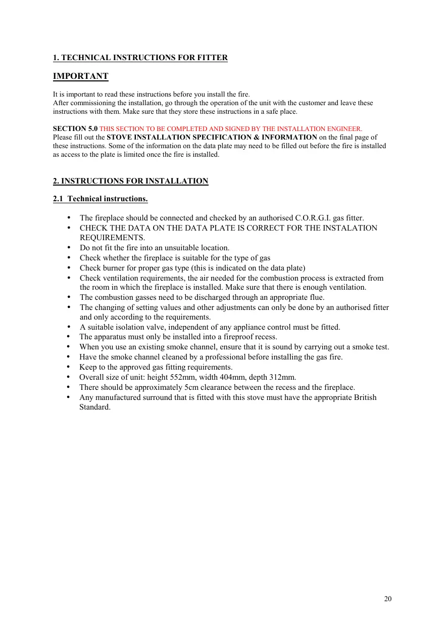
• Overall size of unit: height 552mm, width 404mm, depth 312mm.
• There should be approximately 5cm clearance between the recess and the fireplace.
- Any manufactured surround that is fitted with this stove must have the appropriate British Standard.
2.2 Chimney requirements
When an appliance has previously been connected to the chimney, the chimney must be cleaned by a professional.
Although a gas fireplace can operate well on a little chimney draw, we advise you to have the chimney checked for soundness and correct operation annually.
An approved gas cowl may be fitted to improve the operation of the chimney. It will prevent lift in windy conditions, eliminate downdraught and stop rain and other foreign bodies entering the flue.
2.3 Installation of the fire.
Remove the packaging carefully. Inspect the fire for any signs of damage.
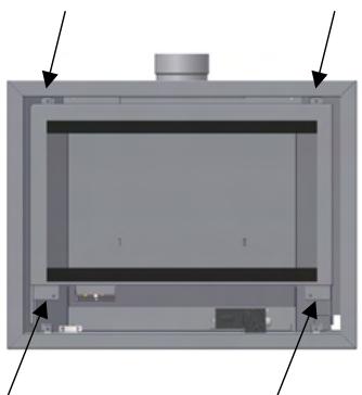
- To remove the front panel that holds the glass: Remove the two screws behind the fold down door, below the front glass panel (FIG. 1) and lift off the frame and glass window.
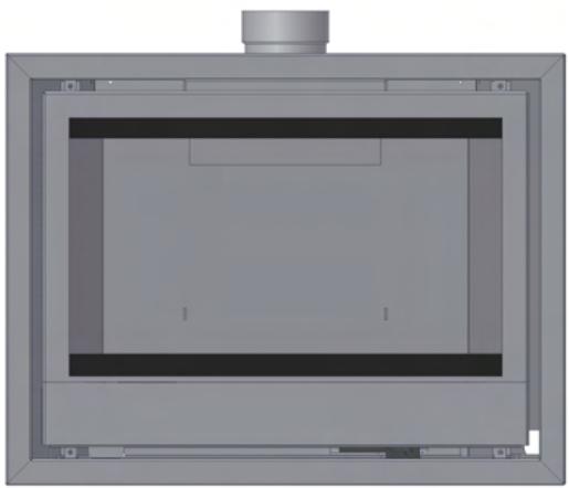
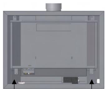
- To remove the outer decorative frame surround: Remove the four screws of the decorative frame and carefully pull it out. (FIG. 2).
natural_image
Interior view of a device frame with arrows indicating orientation (no text or symbols)FIG.1
natural_image
Interior view of a computer monitor case with ventilation grilles and control buttons (no visible text or labels)FIG.2
-
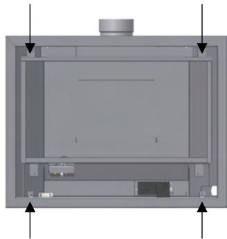
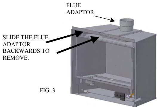
Remove the two screws of the flue adaptor and slide it out of the rails. (FIG. 3)
-
If the chimney is to be lined with a flexible liner, secure this to the flue adaptor using proprietary heat proof sealant. Additional securing may be necessary.
-
Now place the fireplace in the recess and slide the flue adaptor piece back into place, screw the two self tapping screws in place to retain it.
5A. The fireplace recess MUST be capable of withstanding the high temperatures generated by such an appliance.
-
Now make the gas fitting according to the requirements (check 'fitting the gas pipe')
-
Make sure all gas fittings are gas proof.
-
Position the remote control receiver below the burner (see section 3.1 FIG.6)
-
Mount the decorative frame back onto the unit.
-
Put the logs (and vermiculite chips) in place, exactly as per instructions. This is critical to the correct operation of the unit. Check (section 2.9) the chapter on the positioning of the log sets, as these vary depending on whether it is L.P.G. or Natural Gas.
-
Put the glass window and frame back into place and secure with the two self tapping screws. Remember not to touch the glass, because fingerprints cannot be removed after the fireplace has been lit up without stripping it down.
2.4 Fitting the flue.
• The gas fire is fitted with an open draw breaker and downdraught wind diverter.
- The products of combustion must not be able to enter back into the property and therefore the fire must be sealed into the chimney opening, complying with the standard in force at that time. A flexible flue may need to be fitted.
- For the connection between the apparatus and the chimney terminal / channel, use of corrosion free material; that must comply with the latest standards in force at that time; must be used and adequately sealed and attached at each end. The inner diameter of the pipe should be at least 100 mm.
- The connection between the apparatus and the chimney channel should be sound and free of leakage and must be one continuous length with no other joints.
2.5 Fitting the gas pipe.
- An approved gas isolation tap should be fitted in the gas pipe that leads to the appliance, this tap should be easily accessible.
• A minimum, 15mm diameter gas supply pipe should be used to within 1 meter of the appliance. - The final connection to the appliance must be made in 8mm semi-rigid gas pipe. This must be less than 1 meter in length. The inlet valve has an 8mm nut and olive supplied.
- Avoid tension on the gas block when fitting the gas pipe. Support the unit if necessary.
- Check the entire unit for soundness after fitting the gas pipe.
2.6 Ventilation.
The fireplace is a so-called ‘open combustion apparatus’, which means that the air needed for the combustion process is extracted from the room in which the fireplace is installed.
It is important to have enough ventilation in this room. Although the appliance is rated at less than 7kw input, additional ventilation may be necessary in certain circumstances.
2.7 TTB
This apparatus is equipped with TTB safety mechanism, this shuts off the gas supply to the burner when the chimney is blocked. If this is the case, the apparatus will shut down.
When this happens, it is usually an indication of a problem with the chimney. If this is found to be o.k. then check the pilot/gas supply.
2.8 Maintenance.
In order to ensure the safe and correct operation of the gas fire, it should be serviced and cleaned by an authorised professional annually.
There is an annual service record at the back of these instructions that should be filled out each time the appliance is serviced.
The service should include the burner unit, the pilot flame failure device and the combustion chamber.
The ceramic logs should also be inspected for signs of wear and tear. If a log is broken, it should be replaced.
Correct positioning of the logs is critical. (check the chapter on the log sets).
The ceramic glass can be cleaned with a special cleaning product for ceramic cookers or one from your local stockiest.
The decorative frame should be wiped with a lint free cloth or soft brush.
If there is a crack in the glass window, or if the window is broken, it should be replaced before the gas fireplace can be lit up again.
Ensure that the pilot is operating correctly.
2.9 FITTING THE LOG SET
- THE CERAMICS VARY DEPENDING ON WHETHER THE FIRE IS SET TO RUN ON NATURAL GAS OR L.P.G.
• REFER TO THE PICTURES ON THE NEXT PAGES TO ASSIST CORRECT POSITIONING OF THE CERAMICS.
• Take great care when handling the ceramic logs as they are very fragile.
• Refer to the diagrams when laying the logs. - Only use the logs supplied with the fire and NEVER use alternatives or extra coals or logs.
• Incorrect positioning of the ceramics will cause combustion problems within the fire.
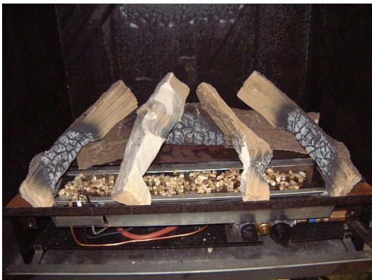
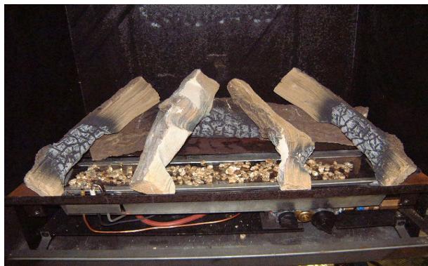
2.9A Fitting the Log set- natural gas.
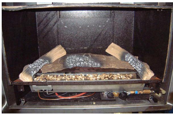
- Firstly, fill the burner plate with the enclosed vermiculite chips (check fig 4a). A thin level layer is ideal.
Caution: never use more grains than the supplied amount.
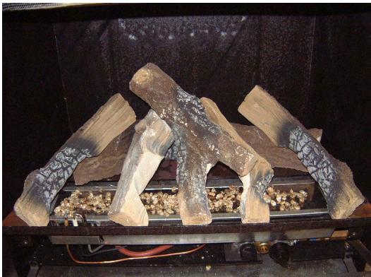
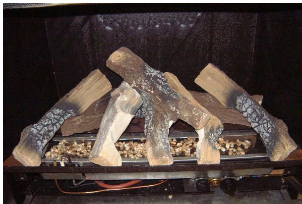
- Now put the logs in place according to fig. 4b and 4c.
Make sure that when you are putting the logs in place, the pilot flame is not obstructed by either a log or vermiculite chips.
The logs must be put in exactly as per these instructions. This is in order to ensure that the flames are impinged as little as possible and thus preventing the disturbance of the flame pattern and possible sooting.
- Replace the glass window and make sure that it is firmly shut before you light the fire.
LOG LAYOUT FOR NATURAL GAS
natural_image
Interior view of a laboratory or industrial chamber with textured materials and wiring (no visible text or symbols)FIG 4A
natural_image
Photograph of a fire safety test setup with firewood logs and coal samples on a metal tray (no visible text or symbols)FIG 4B
natural_image
Photograph of a fire safety cooktop with six firewood logs and scattered gravel on the base (no text or symbols visible)FIG 4C
3.0 USER INSTRUCTIONS
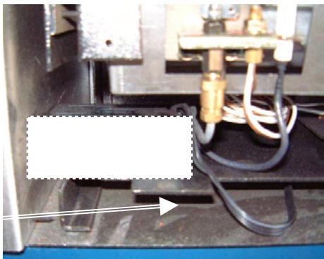
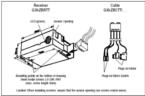
3.1 POSITIONING THE REMOTE CONTROL RECEIVER.
Place the remote control receiver in the bottom left corner of the unit before you mount the decorative frame (check FIG. 6).
Slide the cable between the outer casing and the bottom of the combustion chamber. (check FIG. 6).
natural_image
Close-up of a mechanical testing setup with tubing and a labeled component (no readable text or symbols)FIG. 6
3.2 REMOTE CONTROL
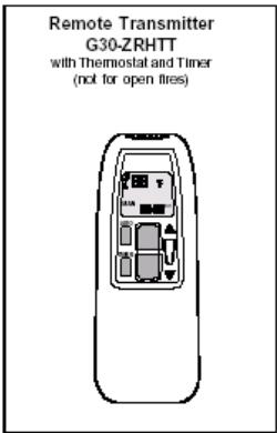
Illustration 1: Components of the Remote Package
TECHNICAL SPECIFICATIONS
Ultrasound Transmission:
Ambient Temperature:
Range:
1...10m
3...33ft.
Frequency:
ON 40,5kHz,
OFF 40kHz
Transmitter & Receiver:
max. 60°C 140°F
Connecting Cables:
max. 180°C 356°F
Batteries required:
Handset: 1 x 9V block (alkaline recommended)
Receiver: 4 x 1,5V AA (alkaline recommended)
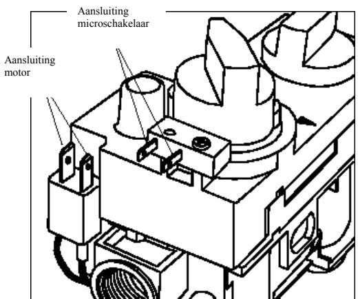
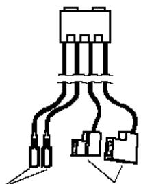
CONNECTIONS
The G30-ZRPTT is intended for use only with motorized gas combination controls models GV34
(or GV36 retrofitted with a motor). The receiver cable must be firmly plugged onto the flat blade
connectors.
motor:
6,3 and 4,8mm;
micro switch:
both 2,8mm
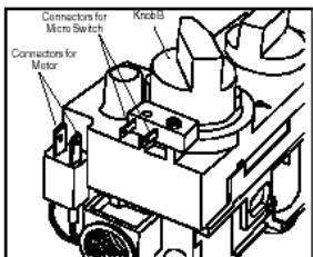
Illustration 2: Cover with Connectors for Micro Switch
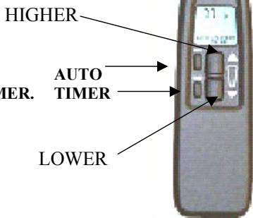
3.3 REMOTE CONTROL OPERATING INSTRUCTIONS
The two large buttons on the remote control hand-set are used to operate the main burner.
The two smaller buttons are for AUTO and TIMER.
Instructions for their use follow.
SETTING THE DISPLAY
After fitting the batteries in the receiver and the hand set, the following options are available:
Adjustment of the digital display (from ‘DEGREES F & 12 HOUR’ to ‘DEGREES C & 24 HOUR’ and vice versa)
- Press the buttons AUTO and TIMER at the same time until the display blinks.
- Now you can switch from F to C and vice-versa by pressing the AUTO button.
- The display will return to “manual operation” after a short time.
SETTING THE TIME
- Press the buttons AUTO and TIMER at the same time, the indications on the screen start to blink.
• To set the time, the ▲ button must be pressed to set the hours. The ▼ button will set the minutes.
To return to manual operation, you need to wait several seconds or push the TIMER button.
SETTING THE DESIRED AUTOMATIC TEMPERATURE
- Press the AUTO button until the “temperature” indication starts to blink.
- Then set the desired temperature by means of the ▲ or ▼ button.
• After that, wait or press AUTO to get to the automatic mode.
The sensor in the remote control measures the temperature in the room. The receiver on the stove compares the room temperature with the pre-set temperature and if necessary, adjusts the height of the flames automatically.
PROGRAMMING THE TIMER FUNCTION
- Keep TIMER button pressed until indication P1 starts to blink.
- Then set the switch-on time by means of the buttons ▲ for hours and ▼ for minutes.
- Press TIMER again, until P1 appears. Then the switch-off time can be set.
• By pressing TIMER once again, the times for the second program, P2 can be set.
• The set times must be confirmed by pressing TIMER again. - Outside the programmed times the symbol will appear.
MANUAL MODE
ADJUSTING THE HEIGHT OF THE FLAMES MANUALLY, ONCE THE PILOT HAS BEEN LIT.
- Press ▲ (HIGHER) to start the fire or to make the flames higher. Press ▼ (LOWER) to make the flames smaller or to switch the fire to the PILOT ON position. On pressing these buttons, the “send” sign will appear in the upper left corner of the display on the handset display.
- When the gas valve has reached its maximum position (open or closed), the LED of the receiver will start blinking, indicating that the highest or lowest position is reached.
AUTOMATIC MODE 'AUTO' in display
Use this mode to set the desired temperature that you would like the room to stay at.
- Press and hold the AUTO button until the display flashes.
- Press either of the buttons (▼) and (▲) to set the desired temperature.
- Wait a few seconds until the set temperature stops flashing or press AUTO to switch to AUTO MODE.
TIMER 'TIMER' IN DISPLAY
Use this mode to switch the Stealth on and off automatically at the times set.
If the timer mode is switched on, temperature control is done in the same way as in the AUTO mode. As soon as the ‘heating cycle off’ time is reached, the Stealth will switch to the
PILOT ON position and there is no temperature control. This minimizes battery consumption.
SWITCHING THE FIRE OFF
We recommend to switch the fire off using the (▼) button; the transmitter will then not be active and will not use up any energy from the batteries.
By pressing either of the buttons (▼) and (▲), you will reach “manual operation”, from any other mode.
CHANGING THE BATTERIES
If “BATT” appears in the top right corner of the display, or if the LED light on the receiver becomes less bright, the batteries needs to be changed.
AUTOMATIC SAFETY SWITCH-OFF:
If the receiver does not receive any signal during a 2 hour period, the unit will switch to the pilot light mode automatically and will switch on again as soon as a new signal is sent.
This may happen for example if the remote control was accidentally removed from the property.
Required batteries: 1x 9v, alkaline for the remote control and 4x AA, 1,5v penlight for the receiver.
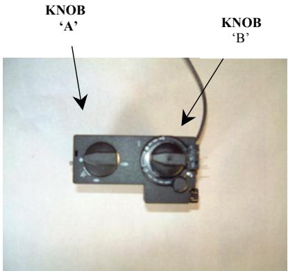
3.4 OPERATING THE FIRE FOR THE FIRST TIME
In the middle of the apparatus, below the main glass there is a drop down door that hides the main controls. (shown below)
- Open the gas tap which is mounted in the gas pipe leading to the fireplace.
- Turn the ignition button (A) clockwise, all the way to the end stop. This is the START (OFF) position for the pilot.
- Depress and turn it anti-clockwise until you hear a click. This is the spark that ignites the pilot being generated.
3A You will be able to see though the glass window, in the front left corner, if the pilot flame has lit. - If the pilot did not light, repeat the previous sequence. (from 2) • If the fire goes out, do not re-ignite for at least 3 minutes.
- If the pilot flame is burning, keep the ignition button pressed for at least 15 seconds, then let it go. The pilot flame should still be burning.
- Now turn button (A) further anti-clockwise, this opens the valve and allows operation of knob (B).
- Knob (B) can now be set (continuously variable) at the desired setting between high and low, manually simply by turning anti-clockwise for higher, clockwise for lower. Or by using the remote control.
You will learn which setting is most suitable for your room through experience.
Operating the remote control is easy. See previous paragraph for details.
3.5 CURING PAINT
After lighting the fire for the first time, an unpleasant scent may develop.
This is caused by the hardening of the heat resistant lacquer on the stove, this scent will disappear after several hours. We therefore advise you to set the flame height as high as possible when you light up the fire for the first time and to ventilate the room in which it is installed.
3.6 USER GUIDELINES.
- Do not use the fire until an authorised fitter has commissioned the unit and carried out the required safety tests.
- The TTB fitted to this appliance is not a substitute for an independently fitted carbon monoxide detector.
- Do not place any combustible objects within 1 meter of the appliance.
When the fire has extinguished you must wait at least 3 minutes before you ignite it again (check taking the fireplace into operation). - In order to ensure the safe and correct operation of the gas fire, it should be checked and cleaned by an authorised professional annually.
- If the fire in the gas fireplace extinguishes repeatedly you should consult your fitter.
- If you ever smell gas, switch the appliance off at the burner control and the isolation tap.
• The front of the gas fireplace is regarded as the heat exchanging surface. - The fireplace may not be used when the glass window is broken or when the door is open.
- The fireplace may only be repaired using original parts supplied by the manufacturer, and repairs may only be done by an authorised fitter.
- You cannot alter or add anything to the log set under any circumstance. If a log is broken, it should be replaced by an original one supplied by the manufacturer.
- The distance between the fireplace and combustible objects or furniture should be at least 1 meter.
- It is important that you do not use the fireplace shortly after a renovation or in a newly built house. The air circulation sucks moisture and unhardened volatile elements of plaster, paint, floor coverings and other materials into the fireplace. This may cause soot stains on cold surfaces.
• NEVER LET CHILDREN PLAY WITH THE REMOTE CONTROL.
• ONLY USE THE REMOTE CONTROL WHEN THE FIREPLACE IS IN YOUR VIEW. - WHEN THE FIREPLACE IS IN OPERATION, CERTAIN PARTS WILL BECOME VERY HOT. IT MAY BE NECESSARY TO FIT A GUARD TO PROTECT CHILDREN, THE ELDERLY AND INFIRM.
• Cleaning of the stove should only be carried out when it is cold.
EXPLODED VIEW OF STOVE COMPONENTS
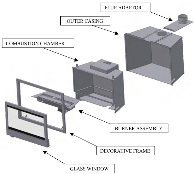
flowchart
graph TD
    A["GLASS WINDOW"] --> B["BURNER ASSEMBLY"]
    B --> C["COMBUSTION CHAMBER"]
    C --> D["OUTER CASING"]
    D --> E["FLUE ADAPTOR"]
    E --> F["DECORATIVE FRAME"]
    F --> G["EXTRACTION chamber"]
TECHNICAL DRAWING
ANNUAL SERVICE RECORD
INSTALLATION DATE OF APPLIANCE:
1ST YEAR SERVICE completion date:
SERVICE ENGINEER:
COMPANY NAME:
COMPANY ADDRESS:
POSTCODE:
CONTACT NUMBER
2ND YEAR SERVICE completion date:
SERVICE ENGINEER:
COMPANY NAME:
COMPANY ADDRESS:
POSTCODE:
3RD YEAR SERVICE completion date:
SERVICE ENGINEER:
COMPANY NAME:
COMPANY ADDRESS:
POSTCODE:
4TH YEAR SERVICE completion date:
SERVICE ENGINEER:
COMPANY NAME:
COMPANY ADDRESS:
POSTCODE:
5TH YEAR SERVICE completion date:
SERVICE ENGINEER:
COMPANY NAME:
COMPANY ADDRESS:
POSTCODE:
6TH YEAR SERVICE completion date:
SERVICE ENGINEER:
COMPANY NAME:
COMPANY ADDRESS:
POSTCODE:
STOVE INSTALLATION SPECIFICATION & INFORMATION
THIS SECTION TO BE COMPLETED AND SIGNED BY THE INSTALLATION ENGINEER
Type gas supply (please tick)
Natural (mains) Gas ____ LPG supply in bulk ____ LPG supply in cylinder ____
Size of Governor setting: (i.e.) Natural Gas 20MBAR. LPG 37MBAR)
Length and size of gas supply: ____
Meter pressure. Fire on only: ____
Other appliances. All on:
Burner pressure. Fire on only ____
Other appliances. All on: ____
Gas rate - Natural Gas - Time for 1 cubic foot in seconds: ____
Overall length of flue: ____
Is there any spillage: ____ Is the draught excessive: ____
Is there any permanent ventilation in the room: ____
Has the room double glazing: ____
Is the aeration of the pilot correct: ____
Does the flame encircle the FFD: ____
Installation Engineers Name: ____ ____
Address ____ ____ ____
Post Code ____
Telephone: ____ Fax: ____ Mobile: ____
Corgi Registration No: ____
Signed: ____
Date: ____
Guarantee
Dear Customer,
Your gas fire, when installed in accordance with the installation instructions and operated in accordance with these instructions, should provide many years of safe and efficient operation.
We thank you for purchasing our product and trust it will provide excellent service.
This appliance carries a guarantee of 2 Years from date of purchase.
The guarantee is void if:
• The appliance is not installed and operated in accordance with our instructions, or
• repairs of modification have been carried out by the purchaser or any third party not authorised by us or:
• the appliance has been misused or accidentally damaged, or:
• damage is due to ‘fair wear and tear.’ or:
• the appliance or defective component(s) are not returned to us, prepaid postage.
This guarantee does not cover the consumable items within the appliance, nor the glass.
The rights given in this guarantee are limited to the UK mainland and are in addition to any to which you may have a statutory entitlement.
Please retain your purchase receipt. We will need to see this in the event of a claim under warranty.
Broseley Fires Ltd.
Knights Way,
Battlefield Enterprise Park,
Shrewsbury,
Shropshire.
SY1 3AB.
Tel: 01743 461444
Fax: 01743 461446
http://www.broseleyfires.com
Wanders
METAALPRODUCTEN B.V.
AMTWEG 4
7077 AL Netterden (NL)
Tel. +31 (0)315-386414
Fax +31 (0)315-386201
e-mail: info@wanders.nl
www.wanders.com
- BORDEAUX
- INHOUDSOPGAVE
- Afstandsbediening.
- INDEX
- DATA SHEET for the Bordeaux gas inset stove.
- TECHNICAL INSTRUCTIONS FOR FITTER
- USER INSTRUCTIONS
- NATURAL GAS (N.G.)
- TECHNICAL INSTRUCTIONS FOR FITTER
- IMPORTANT
- SECTION 5.0 THIS SECTION TO BE COMPLETED AND SIGNED BY THE INSTALLATION ENGINEER.
- INSTRUCTIONS FOR INSTALLATION
- Technical instructions.
- Chimney requirements
- Installation of the fire.
- Fitting the flue.
- Fitting the gas pipe.
- Ventilation.
- TTB
- Maintenance.
- FITTING THE LOG SET
- 2.9A Fitting the Log set- natural gas.
- LOG LAYOUT FOR NATURAL GAS
- POSITIONING THE REMOTE CONTROL RECEIVER.
- REMOTE CONTROL
- TECHNICAL SPECIFICATIONS
- CONNECTIONS
- REMOTE CONTROL OPERATING INSTRUCTIONS
- SETTING THE DISPLAY
- SETTING THE TIME
- SETTING THE DESIRED AUTOMATIC TEMPERATURE
- PROGRAMMING THE TIMER FUNCTION
- MANUAL MODE
- AUTOMATIC MODE 'AUTO' in display
- TIMER 'TIMER' IN DISPLAY
- SWITCHING THE FIRE OFF
- CHANGING THE BATTERIES
- AUTOMATIC SAFETY SWITCH-OFF:
- OPERATING THE FIRE FOR THE FIRST TIME
- CURING PAINT
- USER GUIDELINES.
- EXPLODED VIEW OF STOVE COMPONENTS
- TECHNICAL DRAWING
- ANNUAL SERVICE RECORD
- STOVE INSTALLATION SPECIFICATION & INFORMATION
- THIS SECTION TO BE COMPLETED AND SIGNED BY THE INSTALLATION ENGINEER
- Guarantee
- Wanders
Brand : WANDERS
Model : BORDEAUX
Category : Fireplace insert