
WMS 40 PRO FLEXX - Wireless Microphone System AKG - Free user manual and instructions
Find the device manual for free WMS 40 PRO FLEXX AKG in PDF.

| Product type | UHF wireless microphone system |
| Model | WMS 40 PRO FLEXX |
| Brand | AKG |
| Included components | SR 40 FLEXX receiver, HT 40 FLEXX handheld transmitter or PT 40 FLEXX bodypack transmitter, depending on version |
| Carrier frequency | 660 to 865 MHz (UHF), 3 switchable frequencies per set |
| Modulation | FM |
| Audio bandwidth | 65 - 20,000 Hz (handheld transmitter) / 35 - 20,000 Hz (bodypack transmitter and receiver) |
| Signal-to-noise ratio | Typ. 110 dB(A) |
| Typical range | 3 to 5 meters (optimal distance), with line of sight |
| Receiver power supply | 120/230 V AC, 50/60 Hz via included mains adapter |
| Transmitter power supply | 1 AA 1.5 V battery (LR6); typical battery life 30-31 h |
| Receiver dimensions | 200 x 190 x 44 mm |
| Receiver weight | 630 g |
| Handheld transmitter dimensions | 229 x 53 x 53 mm |
| Handheld transmitter weight | 214 g (without battery) |
| Bodypack transmitter dimensions | 60 x 74 x 30 mm |
| Bodypack transmitter weight | 85 g (without battery) |
| Receiver audio outputs | XLR balanced (mic level) and 6.35 mm jack unbalanced (line level), adjustable |
| Main functions | Diversity with two antennas, adjustable squelch, 3-position frequency selector, RF and AF LED indicators, gain adjustment on transmitter |
| Maintenance and cleaning | Clean surfaces with a damp cloth; wash foam windscreen with soapy water |
| Safety | Use only the supplied adapter (12 V DC); do not expose to moisture; disconnect before cleaning |
| Spare parts and repairability | Opening and repair reserved for authorized personnel; standard AA batteries; interchangeable color clips |
| Optional accessories | RMU 40 PRO rack mount kit, CK 55 L lavalier microphone, C 555 L headset microphone, MKG L guitar cable, windshields |
| General information | Compliant with CE standards; manual available in multiple languages on the AKG website |
Frequently Asked Questions - WMS 40 PRO FLEXX AKG
User questions about WMS 40 PRO FLEXX AKG
0 question about this device. Answer the ones you know or ask your own.
Ask a new question about this device
Download the instructions for your Wireless Microphone System in PDF format for free! Find your manual WMS 40 PRO FLEXX - AKG and take your electronic device back in hand. On this page are published all the documents necessary for the use of your device. WMS 40 PRO FLEXX by AKG.
USER MANUAL WMS 40 PRO FLEXX AKG
Please read the manual before using the equipment!
MODE D'EMPLOI p.36
Figs. 3, 4, 8, 9. 2
Figs. 5, 6, 7, 10 3
Figs. 11 through 16. 4
FCC Statement 22
1 Safety and Environment
1.1 Safety 22
1.2 Environment 22
2 Description
2.1 Introduction 23
2.2 Packing Lists 23
2.3 Optional Accessories 23
2.4 SR 40 FLEXX Receiver 23
2.4.1 Front Panel 24
2.4.2 Rear Panel 25
2.5 HT 40 FLEXX Handheld Transmitter 25
2.5.1 Controls 25
2.6 PT 40 FLEXX Bodypack Transmitter 26
2.6.1 Controls 26
2.6.2 Microphones, Guitar Cable 27
3 Setting Up
3.1 Positioning the Receiver 28
3.2 Connecting the Receiver to a Balanced Input 28
3.3 Connecting the Receiver to an Unbalanced Input 28
3.4 Connecting the Receiver to Power 28
3.5 Inserting and Testing Batteries in the Handheld/Bodypack Transmitters 28
3.6 Setting Up the Handheld Transmitter 29
3.6.1 Replacing the Color Code Clip 29
3.7 Setting Up the Bodypack Transmitter 29
3.7.1 Connecting a Microphone 30
3.7.2 Connecting an Instrument 30
3.7.3 Inserting a Label 30
3.8 Before the Soundcheck 30
3.9 Multichannel Systems 31
3.10 Changing Carrier Frequencies 31
4 Microphone Technique
4.1 HT 40 FLEXX Handheld Transmitter 32
4.1.1 Working Distance and Proximity Effect 32
4.1.2 Angle of Incidence 32
4.1.3 Feedback 32
4.1.4 Backing Vocals 32
4.2 PT 40 FLEXX Bodypack Transmitter 32
4.2.1 CK 55 L Lavalier Microphone 32
4.2.2 C 555 L Head-worn Microphone 33
Positioning the Microphone 33
Windscreen 33
Moisture Shield 33
5 Cleaning
5.1 Surfaces 33
5.2 Handheld Transmitter Internal Windscreen 33
6 Troubleshooting
7 Specifications
7.1 WMS 40 FLEXX. 35
7.2 CK55L,C555L 35
Fig. 17 100

WMS 40 FLEXX
1 Safety and Environment
FCC Statement
This equipment has been tested and found to comply with the limits for a Class B digital device, pursuant to Parts 74 and 15 of the FCC Rules. These limits are designed to provide reasonable protection against harmful interference in a residential installation. This equipment generates, uses, and can radiate radio frequency energy and, if not installed and used in accordance with the instructions, may cause harmful interference to radio communications. However, there is no guarantee that interference will not occur in a particular installation. If this equipment does cause harmful interference to radio or television reception, which can be determined by turning the equipment off and on, the user is encouraged to try to correct the interference by one or more of the following measures:
Reorient or relocate the receiving antenna.
- Increase the separation between the equipment and the receiver.
- Connect the equipment into an outlet on a circuit different from that to which the receiver is connected.
- Consult the dealer or an experienced radio/TV technician for help.
Shielded cables and I/O cords must be used for this equipment to comply with the relevant FCC regulations. Changes or modifications not expressly approved in writing by AKG Acoustics may void the user's authority to operate this equipment.
This device complies with Part 15 of the FCC Rules. Operation is subject to the following two conditions: (1) this device may not cause harmful interference, and (2) this device must accept any interference received, including interference that may cause undesired operation.
1.1 Safety
- Do not spill any liquids on the equipment and do not drop any objects through the ventilation slots in the equipment.
- The equipment may be used in dry rooms only.
- The equipment may be opened, serviced, and repaired by authorized personnel only. The equipment contains no user-serviceable parts.
- Before connecting the equipment to power, check that the AC mains voltage stated on the supplied AC adapter is identical to the AC mains voltage available where you will use the equipment.
- Operate the equipment with the supplied AC adapter with a 12-VDC output. Using adapters with a different output voltage or current type may cause serious damage to the unit.
- If any solid object or liquid penetrates into the equipment, shut down the sound system immediately. Disconnect the AC adapter from the power outlet immediately and have the equipment checked by AKG service personnel.
- If you will not use the equipment for a long period of time, disconnect the AC adapter from the power outlet. Please note that the equipment will not be fully isolated from power when you set the power switch to OFF.
- Do not place the equipment near heat sources such as radiators, heating ducts, or amplifiers, etc. and do not expose it to direct sunlight, excessive dust, moisture, rain, mechanical vibrations, or shock.
- To avoid hum or interference, route all audio lines, particularly those connected to the microphone inputs, away from power lines of any type. If you use cable ducts, be sure to use separate ducts for the audio lines.
- Clean the equipment with a moistened (not wet) cloth only. Be sure to disconnect the AC adapter from the power outlet before cleaning the equipment! Never use caustic or scouring cleaners or cleaning agents containing alcohol or solvents since these may damage the enamel and plastic parts.
- Use the equipment for the applications described in this manual only. AKG cannot accept any liability for damages resulting from improper handling or misuse.
1.2 Environment

- The AC adapter will draw a small amount of current even when the equipment is switched off. To save energy, disconnect the AC adapter from the power outlet if you will leave the equipment unused for a long period of time.
- When scrapping the equipment, separate the case, circuit boards, and cables, and dispose of all components in accordance with local waste disposal rules.
- The packaging of the equipment is recyclable. Dispos of the packaging in an appropriate container provided by the local waste collection/recycling entity and observe all local legislation relating to waste disposal and recycling.
2 Description

2.1 Introduction
Thank you for purchasing an AKG product. This Manual contains important instructions for setting up and operating your equipment. Please take a few minutes to read the instructions below carefully before operating the equipment. Please keep the Manual for future reference. Have fun and impress your audience!
The WMS 40 FLEXX is available in four different kits:
| INSTRUMENTAL SET 1 PT 40 FLEXX bodypack transmitter 1 AA size battery 1 set of lettering labels 1 MKG L guitar cable 1 SR 40 FLEXX receiver 1 AC adapter (see sticker on packaging) 1 Manual Supplement sheet PRESENTER SET 1 PT 40 FLEXX bodypack transmitter 1 AA size battery 1 set of lettering labels 1 CK 55 L lavalier microphone with attachment clip 1 W 55 windscreen 1 SR 40 FLEXX receiver 1 AC adapter (see sticker on packaging) 1 Manual Supplement sheet | SPORTS SET 1 PT 40 FLEXX bodypack transmitter 1 AA size battery 1 set of lettering labels 1 C 555 L head-worn microphone 2 moisture shields 1 W 444 windscreen 1 SR 40 FLEXX receiver 1 AC adapter (see sticker on packaging) 1 Manual Supplement sheet VOCAL SET 1 HT 40 FLEXX handheld transmitter 1 stand adapter 1 AA size battery 1 semitransparent color clip 1 SR 40 FLEXX receiver 1 AC adapter (see sticker on packaging) 1 Manual Supplement sheet |
2.2 Packing Lists
- Check that the packaging contains all of the items listed for your system. Should any of these items be missing, please contact your AKG dealer.
- For optional accessories, refer to the current AKG catalog or folder, or visit www.akg.com. Your dealer will be glad to help.
The SR 40 FLEXX is a stationary diversity receiver for use with all WMS 40 FLEXX and Microtools Series transmitters. It features a half-rack case for mounting in a 19" rack.
Operating in the 660 MHz to 865 MHz UHF range, the SR 40 FLEXX provides three selectable, quartz stabilized carrier frequencies within the 3-MHz-wide frequency band for which you ordered your WMS 40 FLEXX. This allows you to select a different frequency if one of the three frequencies does not provide adequate signal quality. The frequencies have been factory preset to make sure you can set up a multichannel system with up to three channels with three kits operating in the same frequency band. Using a suitable combination of kits operating in different frequency bands you can even use up to nine channels* simultaneously.
The SR 40 FLEXX is a diversity receiver and uses two antennas in order to receive the transmitter signal at two different spots. The diversity electronics will automatically activate the antenna that delivers the better signal.
An adjustable squelch will mute the receiver if the received signal is too weak so the related noise or the self-noise of the receiver will not become audible when the transmitter is switched OFF.
2.3 Optional Accessories
2.4 SR 40 FLEXX Receiver
* Ask your dealer about usable frequency bands for WMS 40 FLEXX systems with more than three channels.
2 Description
1 Antennas: Fixed-length UHF antennas permanently mounted on the front panel. The diversity circuit will automatically activate the antenna that provides the better signal.
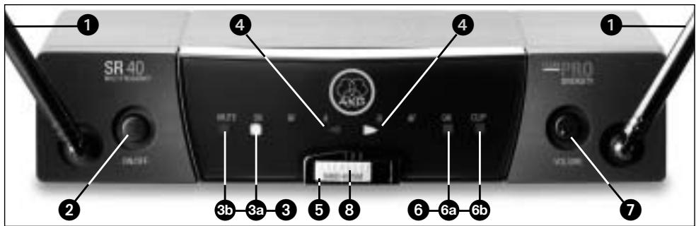
Fig. 1: Front panel controls on SR 40 FLEXX receiver.
2 ON/OFF: On/off pushbutton switch. If the DIVERSITY LEDs A and B flash alternately and the RF MUTE LED is lit constantly, the receiver is ON but receives no signal.
If the RF OK, AF OK, and only one of the two DIVERSITY LEDs are lit, the receiver is ON and receives signal.
When you switch the receiver OFF, all LEDs will extinguish.
3 RF LEDs: These LEDs indicate the quality of the received RF signal.
3a OK (green): This LED is lit to indicate that an RF signal of adequate strength is being received.
3b MUTE (red): This LED is lit to indicate that no signal is being received or the squelch is active. In either case, the audio output will be muted automatically.
4 DIVERSITY LEDs A and B: Indicate which of the two receiving antennas is active at any time.
5 Color code: The color indicates the carrier frequency band of the receiver. Transmitters and receivers tuned to the same frequency band are marked with the same color. Refer to the Manual Supplement sheet for a color code table.
6 AF LEDs: Indicate the received audio level:
6a OK (green): -30 dB to +3 dB
6b CLIP (red): >3 dB. This LED illuminates to indicate the audio level of the received signal is overloading the receiver's audio section.
The green AF OK LED being lit and the red AF CLIP LED flashing occasionally indicate optimum modulation.
If none of the LEDs is lit, the gain setting on the transmitter is too low.
7 VOLUME: This rotary control adjusts the receiver's output level from microphone to line level for matching to the input sensitivity of your mixer or amplifier. The control range is 26 dB.
8 Frequency selector: This slide switch tunes the receiver to one of three different carrier frequencies within the receiver's carrier frequency band.
2 Description

2.4.2 Rear Panel
9 Carrier frequency label: A label indicating the name of the carrier frequency band and the three carrier frequencies of your receiver is affixed to the rear panel of the receiver.
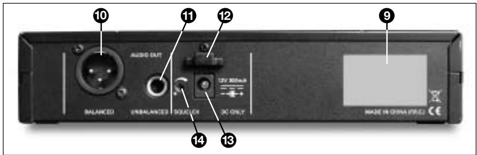
Fig. 2: Rear panel controls on SR 40 FLEXX receiver.
10 AUDIO OUT/BALANCED: Balanced 3-pin XLR audio output for connecting to, e.g., a microphone input on the mixing console.
11 AUDIO OUT/UNBALANCED: Unbalanced audio output on a 1/4" TS jack for connecting to, e.g., a guitar amplifier.
12 Strain relief for the feeder cable of the supplied AC adapter.
13 DC ONLY: Input connector for the supplied AC adapter.
14 SQUELCH: The squelch circuit switches the receiver off if the received signal is too weak, in order to suppress the related noise or the residual noise of the receiver while the transmitter is off. Set the SQUELCH control to minimum before first switching the receiver on.
Operating in the 660 MHz to 865 MHz UHF range, the HT 40 FLEXX provides three selectable, quartz stabilized carrier frequencies within the 3-MHz-wide frequency band for which you ordered your WMS 40 FLEXX. The antenna is integrated in the body.
The microphone element permanently mounted on the transmitter uses a high quality cardioid transducer from AKG. It provides low handling noise sensitivity, high gain before feedback, and brilliant sound quality, as well as a built-in wind and pop filter to reduce wind and breath noise.
2.5 HT 40 FLEXX
Handheld Transmitter
15 On/off switch: This slide switch provides three positions:
ON: Power to the transmitter is on.
MUTE: The signal delivered by the microphone element is muted while power and the RF carrier frequency remain on.
OFF: Power to the transmitter is off.
16 Status LED: Indicates the transmitter's operating status.
LED lit green: Battery is OK.
LED lit red: From the moment the LED changes to red, the battery capacity will provide a maximum of two operating hours. We recommend replacing the battery with a new one as soon as possible.
2.5.1 Controls
Refer to fig. 3 on page 2.
If you use a rechargeable battery, the LED will change to red 15 minutes before the battery will be dead!
17 Frequency selector: This slide switch tunes the transmitter to one of three different carrier frequencies within the transmitter's carrier frequency band.
18 GAIN: This slide switch sets the transmitter's audio input gain in two stages, "HIGH" (high gain) or "LOW" (low gain).
Note:
Refer to fig. 3 on page 2.
2 Description
19 Color code clip: The color of this plastic clip indicates the carrier frequency band of your transmitter. Receivers tuned to the same frequency band are marked with the same color. Refer to the Manual Supplement sheet for a color code table.
You can remove the color code clip on the HT 40 FLEXX and replace it with the supplied semitransparent clip.
20 Battery compartment lid: Refer to section 3.5.
21 Carrier frequency label: The label above the battery compartment indicates the name of the carrier frequency band and the three carrier frequencies of your transmitter.
2.6 PT 40 FLEXX Bodypack Transmitter
You can use the PT 40 FLEXX bodypack transmitter with both dynamic microphones and condenser microphones designed for a supply voltage of approx. 4V . You may also connect an electric guitar, electric bass, or remote keyboard.
Operating in the 660 MHz to 865 MHz UHF range, the PT 40 FLEXX provides three selectable quartz stabilized carrier frequencies within the 3-MHz-wide frequency band for which you ordered your WMS 40 FLEXX.
2.6.1 Controls
Refer to fig. 4 on page 2.
22 On/off switch: This slide switch provides three positions:
ON: Power to the transmitter is on.
MUTE: The signal delivered by the microphone element is muted while power and the RF carrier frequency remain on.
OFF: Power to the transmitter is off.
23 Status LED: Indicates the transmitter's operating status.
LED lit green: Battery is OK.
LED lit red: From the moment the LED changes to red, the battery capacity will provide a maximum of two operating hours. We recommend replacing the battery with a new one as soon as possible.
Note:
If you use a rechargeable battery, the LED will change to red 15 minutes before the battery will be dead!
24 Audio input: 3-pin mini XLR connector with both mic and line level pins that automatically match the connector pinout of the recommended AKG microphones or MKG L guitar cable.
While the MKG L guitar cable is included in the Instrumental Set (see section 2.2 Unpacking), it is also available as an optional accessory.
25 Frequency selector: This slide switch tunes the transmitter to one of three different carrier frequencies within the transmitter's carrier frequency band.
26 Antenna: Permanently connected, flexible antenna.
27 Belt clip for fixing the transmitter to your belt.
28 Battery compartment lid with integrated screwdriver (28a).
28b Viewing window: The viewing window lets you check if there is a dry or rechargeable battery inside the battery compartment. You can also place a white lettering strip (supplied) or a color code strip (optional) behind the viewing window.
29 GAIN: This rotary control inside the battery compartment allows you to match the body-pack transmitter input gain to the microphone or instrument you connected to the transmitter.
30 Carrier frequency label: The label on the transmitter rear panel indicates the name of the carrier frequency band and the three carrier frequencies of your transmitter. Refer to the Manual Supplement sheet for a color code table.
2 Description

2.6.2 Microphones,
Guitar Cable
The PT 40 FLEXX has been designed specifically for use with the following AKG microphones:
CK 55 L
C417L
C520L
C 555 L
C 516 ML
C 518 ML
C 519 ML
The MKG L guitar cable from AKG lets you connect an electric guitar, electric bass, or remote keyboard to the bodypack transmitter. The MKG L guitar cable is included in the Instrumental Set and also available separately as an accessory.


Important!

3 Setting Up
- Before setting up your WMS 40 FLEXX, make sure to set the frequency selectors on the transmitter and receiver to the same frequency (1, 2, or 3). If the transmitter and receiver are tuned to different frequencies, no signal will be received!
- Never use the two audio outputs (BALANCED and UNBALANCED) simultaneously! This may cause signal loss or increased noise.
3.1 Positioning the Receiver
- You can either use the receiver freestanding or mount it in a 19" rack using the optional RMU 40 PRO rack mounting kit. For instructions on how to rack mount the receiver, refer to the RMU 40 PRO manual.
- Reflections off metal parts, walls, ceilings, etc. or the shadow effects of musicians and other people may weaken or cancel the direct transmitter signal. For best results, place the receiver as follows:
- Place the receiver near the performance area (stage). Make sure, though, that the transmitter will never get any closer to the receiver than 10 ft. (3 m). Optimum separation is 16 ft. (5 m).
- Check that you can see the receiver from where you will be using the transmitter.
- Place the receiver at least 5 ft. (1.5 m) away from any big metal objects, walls, scaffolding, ceilings, etc.
3.2 Connecting the Receiver
to a Balanced Input
Refer to fig. 5 on page 3.
3.3 Connecting the Receiver
to an Unbalanced Input Refer to fig. 6 on page 3.
Important!

- Use a standard XLR cable to connect the BALANCED output (10) on the receiver rear panel to a balanced XLR microphone input on the mixer.
- Turn the VOLUME control (7) on the receiver front panel all the way CCW to set the receiver output to microphone level.
3.4 Connecting the Receiver to Power
- Use a standard 1/4 jack cable to connect the UNBALANCED jack (11) on the receiver rear panel to an unbalanced 1/4 line input on the mixer.
-
Turn the VOLUME control (7) on the receiver front panel all the way CW to set the receiver output to line level.
-
To avoid hum interference, do not use audio cables longer than 10 feet (3 m)!
-
Check that the AC mains voltage stated on the included power supply is identical to the AC mains voltage available where you will use your system. Using the power supply with a different AC voltage may cause damage to the unit.
-
Point the antennas (1) upward.
- Plug the feeder cable on the included power supply into the DC ONLY socket (13) on the receiver.
- Bend part of the feeder cable into a small bight, pass the bight through the strain relief (12) from above, and slip the bight over the hook on the strain relief (12). Tighten the cable.
- Plug the AC adapter into a convenient power outlet.
- To switch power to the receiver on, press ON/OFF (2). To switch power to the receiver off, press ON/OFF (2) again.
3.5 Inserting and Testing Batteries in theHandheld/ Bodypack Transmitters
Refer to fig. 8 on page 2.
- Depress the snap hook on the battery compartment lid (20)/(28).
- Pull the battery compartment lid (20)/(28) off the transmitter in the direction of the arrow.
- Insert the supplied battery into the battery compartment conforming to the polarity marks. The transmitter will not function if you insert the battery the other way round.
- Set the on/off switch (15)/(22) to "ON" to switch power to the transmitter on. If the battery is in good condition, the status LED (16)/(23) will be lit green. If the status LED (16)/(23) is lit red, the battery will be dead within about two hours. Replace the battery with a new one as soon as possible.
3 Setting Up
Note:
- If you use a rechargeable battery, the LED will switch to red 15 minutes before the battery will be dead!
If the status LED (16)/(23) fails to illuminate the battery is dead. Insert a new battery.
-
To close the battery compartment, slide the battery compartment lid (20)/(28) onto the battery compartment from below to the point that the snap hook will engage.
-
Set the frequency selector (17) on the transmitter and the frequency selector (8) on the receiver to the same positions (1 - 1, 2 - 2, or 3 - 3).
- Set the SQUELCH control (14) on the receiver to minimum and switch power to the receiver on.
- To switch power to the transmitter on, set the on/off switch (16) to "ON".
- Switch power to your sound system or amplifier on.
-
Talk or sing into the microphone, watching the AF LEDs (6) on the receiver.
-
If the OK LED (6a) flashes rarely and the CLIP LED (6b) will not flash at all, the transmitter input gain is too low. Set GAIN (18) to "HIGH".
-
If OK (6a) is lit constantly and CLIP (6b) flashes frequently or is lit constantly, the transmitter input gain is too high. Set GAIN (18) to "LOW".
-
Set the levels on your mixer or amplifier referring to the appropriate instruction manual, or by ear.
-
Pull the color code clip (19) off the transmitter case in the direction of the arrow.
- Slide the supplied semitransparent replacement clip onto the transmitter to the point that it snaps into place with an audible click.
The PT 40 FLEXX bodypack transmitter has been designed for use with the CK 55 L, C 417 L, C 520 L, C 555 L, C 516 ML, C 518 ML and C 519 ML microphones from AKG. If you wish to connect other microphones from AKG or other manufacturers to the PT 40 FLEXX, please note that you may have to rewire the existing connector on your microphone or replace it with a 3-pin mini XLR connector.
Audio input (24) pinout:
Pin 1: shield
Pin 2:audio inphase (+)
Pin 3: supply voltage
A 4-V positive supply voltage for condenser microphones is available on pin 3.
- Please note that AKG cannot guarantee that the PT 40 FLEXX bodypack transmitter will work perfectly with products from other manufacturers, and any damage that may result from such use is not covered by the AKG warranty scheme.
3.6 Setting Up
the Handheld Transmitter
Also refer to section 4 Microphone Technique.
3.6.1 Replacing
the Color Code Clip
Refer to fig. 9 on page 2.
3.7 Setting Up
he Bodypack Transmitter

Important!
3.7.1 Connecting a Microphone
Refer to fig. 10 on page 3.
Also refer to section 4 Microphone Technique.
3.7.2 Connecting an Instrument
Refer to fig. 10 on page 3.
3.7.3 Inserting a Label
Refer to fig. 4 on page 2.
3.8 Before the Soundcheck
Important!

3 Setting Up
- Set the frequency selector (25) on the transmitter and the frequency selector (8) on the receiver to the same positions (1 - 1, 2 - 2, or 3 - 3).
- Remove the battery compartment lid (28)
- Plug the mini XLR connector on the cable of your microphone into the audio input socket (24) on the bodypack transmitter.
- Set the on/off switch (22) to "ON" to switch power to the bodypack transmitter on.
- Set the SQUELCH control (14) on the receiver to minimum and switch power to the receiver on.
- Talk or sing into the microphone.
- Use the screwdriver (28a) integrated in the battery compartment lid (28) to set the GAIN control (29) to a position where the AF CLIP LED (6b) on the receiver will flash occasionally.
-
Replace the battery compartment lid (28) on the transmitter.
-
Set the frequency selector (25) on the transmitter and the frequency selector (8) on the receiver to the same positions (1 - 1, 2 - 2, or 3 - 3).
- Remove the battery compartment lid (28).
- Plug the jack plug on the MKG L guitar cable into the output jack on your instrument and the mini XLR connector on the guitar cable into the audio input socket (24) on the body-pack transmitter.
- Set the on/off switch (22) to "ON" to switch power to the bodypack transmitter on.
- Set the SQUELCH control (14) on the receiver to minimum and switch power to the receiver on.
- Play your instrument.
- Use the screwdriver (28a) integrated in the battery compartment lid (28) to set the GAIN control (29) to a position where the AF CLIP LED (6b) on the receiver will flash occasionally.
-
Replace the battery compartment lid (28) on the transmitter.
-
Remove the battery compartment lid (28).
- Remove a label from the supplied sheet.
- Letter the label as desired.
- Remove the battery and place the label on the viewing window (28b).
-
Replace the battery and slide the compartment lid (28) back in place on the transmitter.
-
Move the transmitter around the area where you will use the system to check the area for "dead spots", i.e., places where the field strength seems to drop and reception deteriorates.
If you find any dead spots, try to eliminate them by repositioning the receiver. If this does not help, avoid the dead spots.
- The RF OK LED (3a) on the receiver going out means no signal is being received or the squelch is active.
Switch the transmitter on, move closer to the receiver, or set the squelch threshold to the point that the green RF OK LED (3a) will be lit. -
If the received signal is noisy, set the squelch threshold to a level where the noise will stop.
-
Never set the squelch threshold any higher than absolutely necessary. The higher the squelch threshold (-70dB = ., -100dB = .) , the lower the sensitivity of the receiver and thus the usable range between transmitter and receiver.
3 Setting Up

3.9 Multichannel Systems
The spacing between the three carrier frequencies of each WMS 40 FLEXX is wide enough for operating three radio channels simultaneously within the same frequency band with no mutual interference.
For systems with up to nine channels you will need WMS 40 FLEXX kits in up to three different frequency bands. Please ask your dealer which frequency bands are suited for multichannel use and approved for the place where you will use the system. Perform steps 1 through 6 for each frequency band separately.
- Switch power to all transmitters and receivers off.
- Set the frequency selectors on the transmitter and receiver for channel 1 to "1".
- Set the frequency selectors on the transmitter and receiver for channel 2 to "2".
- Set the frequency selectors on the transmitter and receiver for channel 3 to "3".
- Set up the transmitter and receiver for channel 1.
-
Repeat steps 1 through 5 for channels 2 and 3.
-
Never operate two or more wireless channels on the same frequency at the same time and location. This would cause unwanted noise due to radio interference.
- Prior to changing a carrier frequency, be sure to switch the transmitter off. To activate the new carrier frequency, switch the transmitter back on.
Note:
Refer to fig. 17 on page 100.
Refer to sections 3.1
through 3.8 above.

3.10 Changing
Carrier Frequencies

4.1 HT 40 FLEXX Handheld Transmitter
4 Microphone Technique
4.1.1 Working Distance and Proximity Effect
A handheld vocal microphone provides many ways of shaping the sound of your voice as it is heard over the sound system.
The following sections contain useful hints on how to use your HT 40 FLEXX handheld transmitter for best results.
4.1.2 Angle of Incidence Refer to fig. 11 on page 4.
Basically, your voice will sound the bigger and mellower, the closer you hold the microphone to your lips. Moving away from the microphone will produce a more reverberant, more distant sound as the microphone will pick more of the room's reverberation.
You can use this effect to make your voice sound aggressive, neutral, insinuating, etc. simply by changing your working distance.
Proximity effect is a more or less dramatic boost of low frequencies that occurs when you sing into the microphone from less than 2 inches. It gives more "body" to your voice and an intimate, bass-heavy sound.
4.1.3 Feedback Refer to fig. 12 on page 4.
Sing to one side of the microphone or above and across the microphone's top. This provides a well-balanced, natural sound.
If you sing directly into the microphone, it will not only pick up excessive breath noise but also overemphasize "sss", "sh", "tch", "p", and "t" sounds.
Feedback is the result of part of the sound projected by a speaker being picked up by a microphone, fed to the amplifier, and projected again by the speaker. Above a specific volume or "system gain" setting called the feedback threshold, the signal starts being regenerated indefinitely, making the sound system howl and the sound engineer desperately dive for the master fader to reduce the volume and stop the howling.
To increase usable gain before feedback, the microphone element of the HT 40 FLEXX handheld transmitter has a cardioid polar pattern. This means that the microphone is most sensitive to sounds arriving from in front of it (your voice) while picking up much less of sounds arriving from the sides or rear (from monitor speakers for instance).
To maximize gain before feedback, place the main ("FOH") speakers in front of the microphones (along the front edge of the stage).
If you use monitor speakers, be sure never to point any microphone directly at the monitors, or at the FOH speakers.
Feedback may also be triggered by resonances depending on the acoustics of the room or hall. With resonances at low frequencies, proximity effect may cause feedback. In this case, it is often enough to move away from the microphone a little to stop the feedback.
4.1.4 Backing Vocals Refer to fig. 13 on page 4.
- Never let more than two persons share a microphone.
- Ask your backing vocalists never to sing more than 35 degrees off the microphone axis. The microphone is very insensitive to off-axis sounds. If the two vocalists were to sing into the microphone from a wider angle than 35 degrees, you may end up bringing up the fader of the microphone channel far enough to create a feedback problem.
4.2 PT 40 FLEXX dypack Transmitter 4.2.1 CK 55 L Lavalier Microphone
Refer to fig. 14 on page 4.
Note:
- Fix the microphone to the supplied lavalier clip or to the optional H 41/1 tiepin.
-
Clamp the microphone on your clothing as close as possible to the talker's mouth.
-
Remember that gain-before-feedback will be the higher the closer the microphone sits to the user's mouth!
-
Make sure to aim the microphone at the user's mouth.
4 Microphone Technique

4.2.2 C 555 L
Head-worn Microphone
Positioning the Microphone
Refer to fig. 15 on page 4.
- Put the microphone on.
- Bend the gooseneck so that the microphone will sit to one side in front of the corner of your mouth.
Note:
- You can adjust the microphone to conform exactly to the shape of the user's head. For details, refer to the C 555 L instruction manual, which you can download from www.akg.com.
- Should you hear excessive pop noise ("p" and "t" sounds are overemphasized unnaturally), move the microphone capsule further away from your mouth (up or back).
- If the microphone sounds "thin" or flat, move the microphone capsule closer to your mouth (refer to fig. 3).
Find the optimum position during the soundcheck.
Windscreen
If (for instance, in outdoor use) excessive wind or pop noise becomes audible, attach the supplied windscreen to the microphone.
- Slide the windscreen onto the microphone capsule.
- Pull the windscreen over the outer edge of the microphone capsule.
Moisture Shield
Refer to fig. 16 on page 4.
A special moisture shield on the microphone capsule makes it difficult for moisture and makeup to penetrate into the microphone. This barrier prevents the microphone sound entries from being clogged by perspiration or makeup, which would make the sound dull and reduce the sensitivity of the microphone. Therefore, never remove the moisture shield from the microphone!
In case the moisture shield is damaged or lost, the C 555 L head-worn microphone includes a replacement moisture shield.
5 Cleaning

5.1 Surfaces
5.2 Handheld Transmitter Internal Windscreen
-
Use a soft cloth moistened with water to clean the receiver and transmitter surfaces.
-
Unscrew the wire-mesh cap of the handheld transmitter CCW and remove the wire-mesh cap from the transmitter.
- Remove the windscreen (foam sheet) from the wire-mesh cap.
- Wash the windscreen in mild soap suds.
- As soon as the windscreen has dried, replace it in the wire-mesh cap and screw the wire-mesh cap onto the transmitter CW.
6 Troubleshooting
| Problem | Possible Cause | Remedy |
| No sound. | 1. AC adapter is not connected to receiver and/or power outlet.2. Receiver is OFF.3. Receiver is not connected to mixer or amplifier.4. VOLUME control on receiver is at zero.5. Microphone or instrument is not connected to bodypack transmitter.6. Transmitter is tuned to different frequency than receiver.7. Transmitter on/off switch is at "OFF" or "MUTE".8. Transmitter batteries are not inserted properly.9. Transmitter batteries dead.10. Transmitter is too far away from receiver or squelch threshold setting is too high.11. Obstructions between transmitter and receiver.12. Receiver is invisible from transmitter location.13. Receiver is too close to metal objects. | 1. Connect AC adapter to receiver and/or power outlet.2. Push ON/OFF switch to switch receiver ON.3. Connect receiver output to mixer or amplifier input.4. Turn up VOLUME control.5. Connect microphone or instrument to audio input on bodypack.6. Tune transmitter and receiver to same frequency.7. Set transmitter on/off switch to "ON".8. Insert batteries conforming to "+" and "-" marks.9. Replace batteries.10. Move closer to receiver or reduce squelch threshold setting.11. Remove obstructions.12. Avoid spots where you cannot see receiver.13. Move receiver away from or remove interfering objects. |
| Noise, crackling, unwanted signals. | 1. Antenna location.2. Interference from other wireless systems, TV, radio, CB radios, or defective electrical appliances or installations. | 1. Relocate receiver.2. Switch off interference sources or defective appliances, or switch WMS 40 FLEXX to different frequency; have electrical installation checked. |
| Distortion. | 1. GAIN control is set too high or too low.2. Interference from other wireless systems, TV, radio, CB radios, or defective electrical appliances or installations. | 1. Handheld transmitter: Set GAIN to alternative position.Bodypack transmitter: Turn GAIN control down or up just enough to stop the distortion.2. Switch off interference sources or defective appliances, or switch WMS 40 FLEXX to different frequency; have electrical installation checked. |
| Momentary loss of sound ("drops") at some locations within performance area. | · Antenna location. | · Relocate receiver. If dead spots persist, mark and avoid them. |
7 Specifications
| 7.1 WMS 40 FLEXX | |||
| HT 40 FLEXX | PT 40 FLEXX | SR 40 FLEXX | |
| Carrier frequency range | 660 to 865 MHz | 660 to 865 MHz | 660 to 865 MHz |
| Modulation | FM | FM | FM |
| Audio bandwidth | 65 to 20,000 Hz | 35 to 20,000 Hz | 35 to 20,000 Hz |
| Frequency stability (-10°C to +50°C) | ±15 kHz | ±15 kHz | ±15 kHz |
| Rated deviation | 15 kHz | 15 kHz | 15 kHz |
| T.H.D. at 1 kHz | typ. 0.8% | typ. 0.8% | typ. 0.8% |
| Compander | Yes | Yes | Yes |
| Signal/noise ratio | typ. 110 dB(A) | typ. 110 dB(A) | typ. 110 dB(A) |
| RF output | 10 mW | 10 mW | - |
| Current consumption | typ. 70 mA | typ. 75 mA | 115 mA/12 V |
| Power requirement | 1 x 1.5 V AA size battery (LR 6 to IEC 86-L) | 1 x 1.5 V AA size battery (LR 6 to IEC 86-L) | 120/230 VAC 50/60 Hz |
| Battery life | typ. 31 hours (for 2200 mAh) | typ. 30 hours (for 2200 mAh) | - |
| Audio input level for rated deviation | - | 25 to 750 mV/1 kHz, adjustable | - |
| Input impedance | - | 1 Mohm | - |
| Condenser mic power supply | - | 4 V/4.7 kohms (pin 3) | - |
| Squelch threshold | - | - | -100 dBm to -70 dBm, adjustable |
| Audio outputs | - | - | bal. XLR and unbal. 1/4" jack: ad-justable from mic to line level. Output level at rated deviation: 500 mV rms |
| Size | 229 x 53 x 53 mm (9 x 2.1 x 2.1 in.) | 60 x 74 x 30 mm (2.4 x 2.9 x 1.2 in.) | 200 x 190 x 44 mm (7.8 x 7.4 x 1.7 in.) |
| Net weight | 160 g (5.7 oz.) | 60 g (2.1 oz.) | 630 g (1.4 lbs.) |
| 7.2 CK 55 L, C 555 L | ||
| CK 55 L | C 555 L | |
| Type | Pre-polarized condenser microphone | Pre-polarized condenser microphone |
| Polar pattern | cardioid | cardioid |
| Frequency range | 80 Hz to 14 kHz | 80 Hz to 20 kHz |
| Sensitivity | 0.25 mV/Pa (-72 dBV re 1 V/Pa) | 35 mV/Pa (-29 dBV re 1 V/Pa) |
| Electrical impedance at 1 kHz | 1000 ohms | 200 ohms |
| Supply voltage | 1.5 to 10 V from AKG WMS bodypack transmitter | B 29 L battery supply, MPA V L phantom power adapter, AKG WMS bodypack transmitters |
| Cable length | 1.6 m (5 ft. 4 in.) | 1.5 m (5 ft.) |
| Connector | 3-pin mini XLR | 3-pin mini XLR |
| Finish | matte black | matte black |
| Size | 8 dia. x 22 mm (0.3 x 0.9 in.) | length: 195 mm (7.7 in.), max. diameter: 134 mm (5.3 in.) |
| Net weight | 3 g (0.1 oz.) (w/o cable) | 26 g (0.9 oz.) |
This product conforms to the standards listed in the Declaration of Conformity. To order a free copy of the Declaration of Conformity, visit http://www.akg.com or contact sales@akg.com.
Table des matieres
Page
Figs. 3, 4, 8, 9. 2
Figs. 5, 6, 7, 10 3
Figs. 11 a 16 4
6 Resolver problemas 97
7 Especificações 99
7.1 WMS 40 FLEXX. 99
7.2 CK55L,C555L 99
Fig. 17 100
4.1.4 Coro accompanying
6 Resolver problemas
6 Resolver problemas
For other products and distributors worldwide visit www.akg.com

C E ① ROHS OK
H A Harman International Company
Technische Änderungen vorbehalten. Specifications subject to change without notice. Ces caractéristiques sont susceptibles de modifications. Ci riserviamo il dirito di effettuare modifiche tecniche. Nos reservamos el correcho de introduir modificaciones sociales. Especificações sujeitas a mudancas sem aviso prévio.
Printed in China (P.R.C.)
01/08/9100U12530

- Safety and Environment
- Description
- Setting Up
- Microphone Technique
- Cleaning
- Troubleshooting
- Specifications
- FCC Statement
- Safety
- Environment
- HT 40 FLEXX
- Handheld Transmitter
- Controls
- Refer to fig. 3 on page 2.
- Note:
- PT 40 FLEXX Bodypack Transmitter
- Controls
- Positioning the Receiver
- Connecting the Receiver
- Connecting the Receiver
- Connecting the Receiver to Power
- Inserting and Testing Batteries in theHandheld/ Bodypack Transmitters
- Connecting a Microphone
- Connecting an Instrument
- Inserting a Label
- Before the Soundcheck
- HT 40 FLEXX Handheld Transmitter
- Working Distance and Proximity Effect
- Angle of Incidence Refer to fig. 11 on page 4.
- Feedback Refer to fig. 12 on page 4.
- Backing Vocals Refer to fig. 13 on page 4.
- PT 40 FLEXX dypack Transmitter 4.2.1 CK 55 L Lavalier Microphone
- Table des matieres
- Coro accompanying
- Resolver problemas
- H A Harman International Company
Brand : AKG
Model : WMS 40 PRO FLEXX
Category : Wireless Microphone System