
AS 16X12 - Professional audio equipment AKG - Free user manual and instructions
Find the device manual for free AS 16X12 AKG in PDF.

| Product Type | Automatic Audio Mixing Console |
| Brand | AKG |
| Model | AS 16X12 |
| Category | Professional Audio Equipment |
| Number of Inputs | 16 MIC/LINE inputs |
| Number of Outputs | 12 outputs (8 LINE + 4 LINE/MIC) |
| Rack Format | 19 inches, 2U |
| Power Supply | Included 20 V AC mains adapter |
| Control Interface | RS-232 (LecNet) |
| Main Functions | Automatic mixing, equalizer, routing matrix, programmable inputs/outputs, room combining |
| Programmable Control Inputs | 17 pins (dry contact or 0-5 V DC voltage) |
| Programmable Control Outputs | 19 pins (contact to ground, max 40 V/100 mA) |
| Phantom Power | +15 V on each input (switchable) |
| Gain Ranges | 0 dB (Line), +30 dB (condenser mic), +50 dB (dynamic mic) |
| Cascade Compatibility | Up to multiple units for more than 16 channels |
| Included Software | LecNet for AKG (on CD-ROM) |
| Included Accessories | Mains adapter, RS-232 cable, LecNet extension cable, 7.5 cm audio cable |
| Maintenance and Cleaning | Disconnect before cleaning, use a slightly damp cloth, avoid abrasive products or alcohol |
| Safety | Do not open, keep dry, do not use near heat sources, disconnect if unused for long periods |
| Repairability | Repair by authorized technical personnel only |
| Environment | Recycle housing, electronics, and cables separately according to local regulations |
Frequently Asked Questions - AS 16X12 AKG
User questions about AS 16X12 AKG
0 question about this device. Answer the ones you know or ask your own.
Ask a new question about this device
Download the instructions for your Professional audio equipment in PDF format for free! Find your manual AS 16X12 - AKG and take your electronic device back in hand. On this page are published all the documents necessary for the use of your device. AS 16X12 by AKG.
USER MANUAL AS 16X12 AKG
Please read the manual before using the equipment!
- Zeichnen Sie einen Plan des Konferenztisches, für den Sie eine Mix-Minus-Anlage aufbauen müssen.
Zeichnen Sie auch die Ein-und Ausgänge möglichst deutlich ein. - Notieren Sie, welcher Eingang mit welchem Ausgang verbunden ist, sowie den dazugehörigen Pegel. (Der Zeitaufwand loht sich, da sie damit jederzeit den Überblick gehalten.)
- Klichen Sie auf "Matrix Setup" und übertragen Sie die aufgezeichneten Einstellungen in den Computer. Abb. 17 zeigt ein Beispiel für eine Mix-Minus-Einstellung.
-
Speichern Sie ihre Einstellungen in einem Preset.
-
Do not spill any liquids on the equipment and do not drop any objects through the ventilation slots in the equipment.
- The equipment may be used in dry rooms only.
- The equipment may be opened, serviced, and repaired by authorized personnel only. the equipment contains no user-serviceable parts.
- Before connecting the equipment to power, check that the AC mains voltage stated on the supplied AC adapter is identical to the AC mains voltage available where you will use the equipment.
- Operate the equipment with the supplied 20-V AC adapter. Using adapters with a DC output and/or a different output voltage may cause serious damage to the unit.
- If any solid object or liquid penetrates into the equipment, shut down the sound system immediately. Disconnect the AC adapter from the power outlet immediately and have the equipment checked by AKG service personnel.
- If you will not use the equipment for a long period of time, disconnect the AC adapter from the power outlet. Please note that the equipment will not be fully isolated from power when you set the power switch to OFF.
- Do not place the equipment near heat sources such as radiators, heating ducts, or amplifiers, etc. and do not expose it to direct sunlight, excessive dust, moisture, rain, mechanical vibrations, or shock.
- To avoid hum or interference, route all audio lines, particularly those connected to the microphone inputs, away from power lines of any type. If you use cable ducts, be sure to use separate ducts for the audio lines.
- Clean the equipment with a moistened (not wet) cloth only. Be sure to disconnect the AC adapter from the power outlet before cleaning the equipment! Never use caustic or scouring cleaners or cleaning agents containing alcohol or solvents since these may damage the enamel and plastic parts.
- Use the equipment for the applications described in this manual only. AKG cannot accept any liability for damages resulting from improper handling or misuse.
1.1 Safety
- The AC adapter will draw a small amount of current even when the equipment is switched off. To save energy, disconnect the AC adapter from the power outlet if you will leave the equipment unused for a long period of time.
- When scrapping the equipment, separate the case, circuit boards, and cables, and dispose of all components in accordance with local waste disposal rules.
1.2 Environment

The AS 16x12 from AKG is an automatic audio mixer with 16 inputs, 12 outputs, and a crosspoint matrix system for all audio channels in a 2-U rack mount case. The AS 16x12 provides an RS-232 interface and connections for a number of remote controlled functions. To create a sound system with more than 16 microphone channels, you can connect several AS 16x12s together.
For more details refer to the AS 16x12 Owner's Manual.
2.1 Introduction
2.2 Packing List
1xAS16x12
1 x AC adapter
1 x CD-ROM with "LecNet for AKG" software
1 x RS-232 cable
1 x IC AS 8 LecNet expansion cable
1 x 3-in. (7.5-cm) audio expansion cable
3 Installation and Interfacing

- Install the unit in your 19" rack.
- If you use only one unit, set the MASTER/SLAVE switch to "MASTER".
3.1 Rack Mounting
3.2 Daisy Chaining
To obtain a matrix mixer with 32, 48, or 96 inputs and 12 outputs, you can daisy-chain several AS 16x12s.
- Set the MASTER/SLAVE switch on the unit in the highest slot in the rack to "MASTER".
- Set the MASTER/SLAVE switches on all other units to "SLAVE".
- Use the supplied 30-conductor flat cable to connect the AUDIO EXPANSION IN connector on the master AS 16x12 to the AUDIO EXPANSION OUT connector on the first slave and so on. (Refer to fig. 1.)
- Use the supplied LecNet expansion cable to connect the EXPANSION IN port on the "Master" to the EXPANSION OUT port on the first "Slave" and so on as shown in fig. 1.
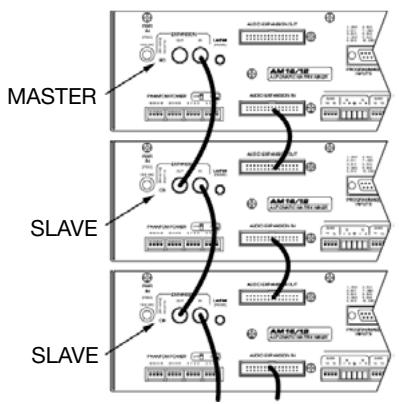
Fig. 1: Daisy-chaining several AS 16x12s
The supplied IC AS 8 LecNet expansion cable carries the
following signals: main audio output, RS-232RX, RS-232TX, and ground. It also allows you to connect the AS 16x12 together with one or more AS 8/AS 8 TCs and/or DFM 4x4s. Refer to fig. 2 on page 8 for an example.
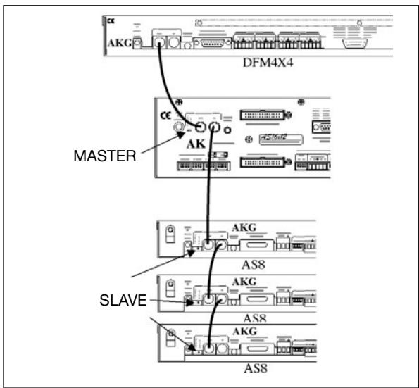
Fig. 2: Connecting an AS 16x12 to a DFM 4x4 and several AS 8s.
- Use the supplied LecNet expansion cable to connect the EXPANSION IN port on the "Master" AS 16x12 to the EXPANSION OUT port on the first "Slave" and so on as shown in fig. 2.
Note: On the DFM 4x4, it makes no difference whether you connect the cable to EXPANSION IN or EXPANSION OUT, because the DFM 4x4 sends and receives RS-232 signals only. - Since all units are set to the same address at the factory, be sure to assign a specific, unequivocal address (a number between 128 and 256) to each unit before first operating the sound system. Connect the units to the computer one at a time and set each address referring to section 4.1 "Installing the Software".
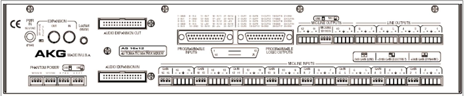
Fig. 3: AS 16x12 rear panel
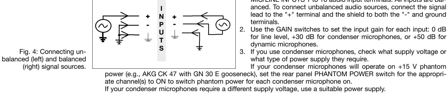
3.3 Audio Inputs
3.4 Audio Outputs
- Connect the audio outputs on the AS 16x12 to the desired devices. While LINE OUTPUTS 1 through 8 are line level only, you can set LINE OUTPUTS 9 through 12 to microphone level with the MIC/LINE switch, to match the output level to, say, a recording device with mic level inputs. All outputs are balanced, but you may also connect unbalanced devices. Connect the hot wire of the cable to the "+" terminal and the shield to ground. Be sure to leave the "-" terminal floating!
3.5 Connecting to the Computer
Use the supplied RS-232 cable to connect the LecNet (RS-232) port on the AS 16x12 rear panel to the RS-232 port on your computer.
3.6 Wiring Programmable Input Pins
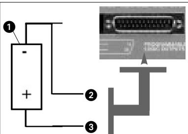
The 17 Programmable Input pins can control a variety of AS 16x12 parameters. Each input can respond to either a contact closure or a continuous voltage. Figs. 5 to 7 show some common connections to the Programmable Input pins. Each Programmable Input is internally pulled up though a 100K resistor to +5 VDC, so no external pull-ups are necessary. When using a continuous voltage with one of the Programmable Inputs, set the function of the Programmable Input to either "Analog Input Control" or "Analog Output Control" in the "Function" line on the "Prog. Inputs" tab in the control panel of the LecNet software.
Fig. 5: Using a 10k linear pot (1) for analog gain control.
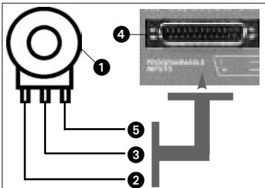
2 = CCW ground.
3 = Center pin -> PROGRAMMABLE INPUT pin (4).
5 = CW - > + 5V
Fig. 6: Contact closure (1).
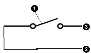
2 = ground,
3 = connection to PROGRAMMABLE INPUT pin.
Figs. 5 through 7.
2 = ground,
3 = connection to PROGRAMMABLE INPUT pin.
Fig. 7: DC voltage source (1), continuously adjustable from 0V to +5V .
The 19 Programmable Output pins of the AS 16x12 can indicate the current state of a Programmable Input.
Each Programmable Output is the electrical equivalent of a contact closure to ground. When a Programmable Output is "active", it conducts current to ground. The maximum acceptable voltage for each Programmable Output is 40V and they will safely conduct up to 100mA DC continuous.
You may run LEDs from the +5 VDC pin on the Programmable Input connector as long as the total LED current for all LEDs on does not exceed 100 mA.
Similarly, you may also run 5-V relay coils from the +5 VDC pin on the Programmable Input connector, as long as the total coil current does not exceed 100mA .
Note that fig. 10 shows an external DC source powering the relay coil. This will be necessary if coil voltages above 5V are needed.
Figs. 8 to 10 show some common connections to Programmable Output pins:
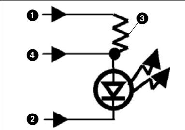
Fig. 8: LED is ON when the Programmable Output is active.
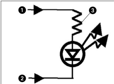
1 = +5 VDC from PROGRAMMABLE
INPUT pin 14, 17, 20, or 23
2 = PROGRAMMABLE LOGIC OUTPUT pin
3 = 380
Fig. 9: LED is OFF when the Programmable Output is active.
1 = +5 VDC from PROGRAMMABLE
INPUT pin 14, 17, 20, or 23
2 = PROGRAMMABLE LOGIC OUTPUT pin
3 = 380
4 = Gnd (from PROGRAMMABLE
LOGIC OUTPUT pin 15, 17, 19,
21, 23, or 25)
Fig. 10: Relay is ON when the Programmable Output is active. Max. coil current is 100mA .
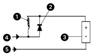
1 = Relay coil
2 = 1N001 diode or equivalent
3 = External DC voltage source (<40 VDC)
4 = PROGRAMMABLE LOGIC OUTPUT pin
5 = Gnd (from PROGRAMMABLE
LOGIC OUTPUT pin 15, 17, 19,
21, 23, or 25)
3.7 Wiring
Programmable Output Pins
3.8 Connecting to Power
4 Operating Notes

Figs. 8 through 10.
- Connect the cable on the supplied AC adapter to the PWR IN jack on the AS 16x12 rear panel.
-
Connect the AC adapter to a convenient power outlet.
-
Insert the CD-ROM into your drive. The installation program will start automatically.
- Follow the on-screen instructions.
- Enter your name and company name when asked and we you to accept the default directory.
- If you are not familiar with the LecNet software we recommend you to choose "Typical" installation.
- Click on "Next" and accept the given setting by double-clicking on "Next" again.
- To complete the installation, click on "Finish" when asked for.
- You can now start the software anytime by clicking on "Start/Program/LecNet for AKG".
4.1 Installing the Software
4.2 Setting Up the Before starting the program:
- Check that the AS 16x12 is connected to your computer. If it is not, use the supplied RS-232 cable to connect the AS 16x12 to the computer. Switch power to the AS 16x12 ON.
Important!
- Prior to all manipulation and interconnection make sure you have equipped all the devices with a unique address, a number between 128 and 256. To change an address, connect only one device to the computer and set the MASTER/SLAVE switch to "MASTER" mode.
4.3 Selecting Devices
- Launch the software at "Start/Programs/LecNet for AKG/LecNet Master Pro" or double click on the shortcut to LecNet Master Pro you might have created on your desktop.
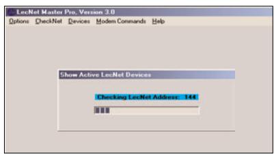
The LecNet program will run a check to see which devices are connected to your computer, thus automatically find the AS 16x12 you have linked to your computer.
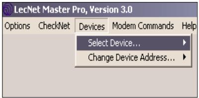
Fig. 11: Checking LecNet Addresses...
-
In the Lecnet Master Pro screen that has popped up, click on "Devices/Select Device....". The addresses of all your connected devices will pop up.
-
Click on the device you want to program. This will get you to an active programming screen for your AS 16x12.
Fig. 12: Programming screen for the AS 16x12.
4.4 Setting Parameters 4.4.1 Input Gain
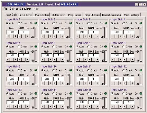
Fig. 13: "Input Gain" tab.
- Click on "Input Gain" and set each input either to "Auto" or "Direct" mode as desired. "On" will be lit to indicate the channel is ON (attenuated by less than 6 dB).
- Use the "Gain" scroll bar to set the input gain.
- Use the "NOM Bus" scroll bar to assign the input to the desired NOM bus.
- When finished in a tab save your setting in a Preset by clicking on "File/Save Active Setup to Disk File...." to save it on your computer or "Save Active Setup to AS 16x12 Preset" to save it on the AS 16x12.
4.4.2 Equalizer
- Click on the "Matrix Setup" tab and set up your Matrix.
-
Save your settings to a Preset.
-
Click on "Input Tone" and set the desired amounts of hi cut/boost and/or low cut for each input.
- Save your settings to a Preset.
4.4.3 Crosspoint Matrix System
4.4.4 Output Gain
- Click on the "Output Gain" tab and set your Output gains as well as the minimum and maximum values for remote control via the Programmable Inputs.
The "Master Output" section enables you to apply gain changes to several outputs at the same time. - Save your settings to a Preset.
4.5 Programmable Inputs
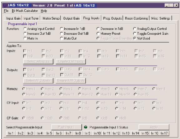
Fig. 14: "Prog. Input" tab
- Click on "Prog. Inputs".
- Select the Programmable Input you would like to program (In 1 to In 17) from the "Select Programmable Input" list on the bottom of the tab.
- Select the function you would like to execute, for instance, a "Preset Recall".
- In the "Preset" line, choose the Preset you want to recall. If your function is an analog input or output control, increase or decrease in volume, or a signal mute, select the corresponding input or output from "Applies To: Inputs" or "Applies To: Outputs". To select a crosspoint gain, choose "CP Input" or "CP Gain".
- Click on "Apply".
- Save your settings to a Preset. Note that a Programmable Input pin can have a different function in every Preset.
Note: You can set the "Toggle Room Boundary" function in the "Room Combining" tab only.
Note: If the "Room Combining" and "Prog. Inputs" tabs are active at the same time, you can assign no function to Programmable Inputs 1 to 6 (max.).
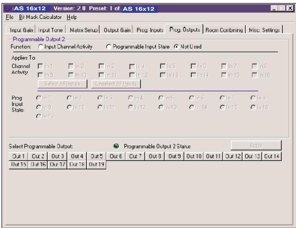
- Click on "Prog. Outputs".
- Select the Programmable Output you wish to program from the list on the bottom of the tab.
Note: If the "Room Combining" and "Prog. Inputs" tabs are active at the same time, you can assign no function to Programmable Inputs 1 to 6 (max.). - Under "programmable Output x" ("Programmable Output 1" in the example in fig. 15), select one of three functions:
"Input Channel Activity": Under "Applies To:/Channel Activity", click on the input channels you wish to use to activate the selected Programmable Output. In the example in fig. 15, Programmable Output 1 is activated when there is activity in microphone channel 1, 2, or 3. "Programmable Input State": Under "Applies To:/Channel Activity", click on the Programmable Input(s) you wish to use to activate the selected Programmable Output. Use this function to activate an LED or a relay.
"Not Used": To deactivate the selected Programmable Output, click on "Not Used".
- Save your settings to a Preset.
As with the Programmable Inputs, you can assign a different function to each Programmable Output in each Preset.
4.6 Programmable Outputs
Fig. 15: "Porg. Outputs" tab.
- Recall the Preset with the desired parameters (input and output gain, EQ settings, etc.).
- Click on "Room Combining" and "Active".
- Select the "Number of Rooms" that you may need to combined ("2", "3", or "4").
- Select the "Room Boundaries", each of which represents a removable partition between Rooms.
- In the fields "Inputs to Output 1" through "Inputs to Output 4", assign each input to the desired output or outputs.
- Click on "Apply" and note the currently active functions of the Programmable Inputs. The functions are shown in the yellow fields.
- Save your settings to a Preset.
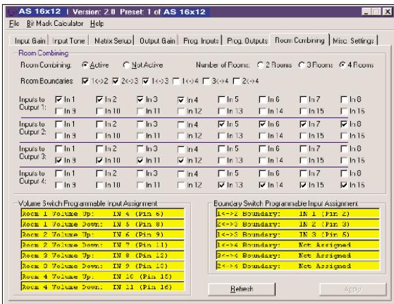
4.7 Room Combining
Fig. 16: "Room Combining" tab.
- Get a piece of paper and draw the layout of the conference table for which you have to set up a mix-minus system.
Be sure to include the ins and outs in a manner that you can easily identify them. - Note which input is routed to which output and add the associated levels. (This may seem a lot of work, but will save you a lot of time and trouble when you actually install the system.)
- Click on "Matrix Setup" and transfer the settings in your layout to the computer. Fig 17 shows an example of a mix-minus setup.
- Save your settings to a Preset.
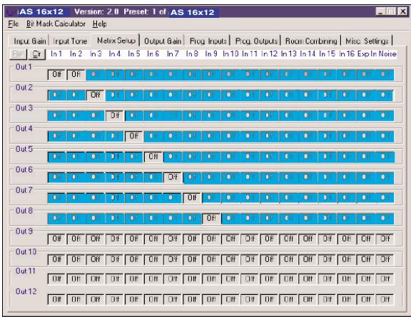
4.8 Complex Matrix Setups
Fig. 17: Example of a mix-minus setup.
1.1 Sécurité
3.1 Montaggio in rack
4 = conexão de massa atraves do pino PROGRAMMABLE LOGIC OUTPUT 15, 17, 19, 21, 23 ou 25
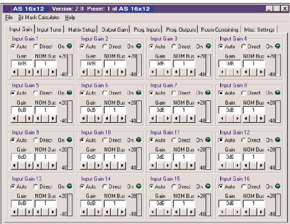
Fig. 13: submenu "Input Gain"

Fig. 16: submenu "Room Combining"
4.7 Combinar salas
914 Airpark Center Drive, Nashville, TN 37217, U.S.A., Tel: (615) 620-3800, Fax: (615) 620-3875, http://www.akgusa.com, e-mail: akgusa@harman.com
For other products and distributors worldwide visit http://www.akg.com
- Safety
- Environment
- Introduction
- Packing List
- Installation and Interfacing
- Rack Mounting
- Daisy Chaining
- Audio Outputs
- Connecting to the Computer
- Wiring Programmable Input Pins
- Wiring
- Programmable Output Pins
- Operating Notes
- Setting Up the Before starting the program:
- Important!
- Selecting Devices
- Setting Parameters 4.4.1 Input Gain
- Equalizer
- Crosspoint Matrix System
- Output Gain
- Programmable Inputs
- Sécurité
- Montaggio in rack
Brand : AKG
Model : AS 16X12
Category : Professional audio equipment