
KV8-MAX3 - Motherboard ABIT - Free user manual and instructions
Find the device manual for free KV8-MAX3 ABIT in PDF.

User questions about KV8-MAX3 ABIT
0 question about this device. Answer the ones you know or ask your own.
Ask a new question about this device
Download the instructions for your Motherboard in PDF format for free! Find your manual KV8-MAX3 - ABIT and take your electronic device back in hand. On this page are published all the documents necessary for the use of your device. KV8-MAX3 by ABIT.
USER MANUAL KV8-MAX3 ABIT
Socket 754 System Board User's Manual
Copyright and Warranty Notice
The information in this document is subject to change without notice and does not represent a commitment on part of the vendor, who assumes no liability or responsibility for any errors that may appear in this manual.
No warranty or representation, either expressed or implied, is made with respect to the quality, accuracy or fitness for any particular part of this document. In no event shall the manufacturer be liable for direct, indirect, special, incidental or consequential damages arising from any defect or error in this manual or product.
Product names appearing in this manual are for identification purpose only and trademarks and product names or brand names appearing in this document are the property of their respective owners.
This document contains materials protected under International Copyright Laws. All rights reserved. No part of this manual may be reproduced, transmitted or transcribed without the expressed written permission of the manufacturer and authors of this manual.
If you do not properly set the motherboard settings, causing the motherboard to malfunction or fail, we cannot guarantee any responsibility.
Table Of Contents
KV8-MAX3 快速安装指引 2
Chapter 2. Hardware Setup 2-1
2-1. Install The Motherboard.. 2-1
2-2. Install CPU and Heatsink 2-2
2-3. Install System Memory 2-3
2-4. Connectors, Headers and Switches 2-5
(1).ATX Power Input Connectors. 2-5
(2). FAN Connectors. 2-6
(3). CMOS Memory Clearing Header 2-7
(4). Wake-up Header. 2-8
(5). Front Panel Switches & Indicators Headers 2-9
(6). Additional USB Port Headers 2-10
(7). Additional IEEE1394 Port Header. 2-11
(8). Front Panel Audio Connection Header 2-12
(9). Internal Audio Connectors 2-13
(10). Accelerated Graphics Port Slot 2-13
(11). Floppy Disk Drive Connector. 2-14
(12). IDE Connectors. 2-15
(13). POST Code Display 2-16
(14). Serial ATA Connectors 2-17
(15). Status Indicators. 2-18
(16). System Management Bus Headers. 2-19
(17). Back Panel Connectors 2-20
Chapter 3. BIOS Setup 3-1
3-1. SoftMenu Setup.. 3-3
3-2. Standard CMOS Features 3-5
3-3. Advanced BIOS Features 3-8
3-4. Advanced Chipset Features.. 3-10
3-5. Integrated Peripherals 3-14
3-6. Power Management Setup 3-17
3-7. PnP/PCI Configurations 3-19
3-8. PC Health Status 3-21
3-9. Load Fail-Safe Defaults 3-24
3-10. Load Optimized Defaults 3-24
3-11. Set Password 3-24
3-12. Save & Exit Setup 3-24
3-13. Exit Without Saving 3-24
Appendix A. Install VIA 4-in-1 Driver
Appendix B. Install Audio Driver.. 2
Appendix C. Install LAN Driver..
Appendix D. Install VIA USB 2.0 Driver
Appendix E. Install VIA Serial ATA RAID Driver..
Appendix F. Install Silicon Serial ATA RAID Driver..
Appendix G. Install ABIT μGuru Driver. 1
Appendix H. POST Code Definition.. H-1
Appendix I. Troubleshooting (Need Assistance?) 1-1
Appendix J. How to Get Technical Support..

KV8-MAX3 快速安装指引
YctaHObKa MaTePHHcKoI IlaTbI B KopNVC
IocJe yctAHOBKN IpoIeCCopa Ha MaTePHHcKyo IJIaTy MOxHO HauHHaThy cTaTHOBKY MaTePHHcKOI IJIaTbB KOpIyc. BoJIbIIaA qacTb KopNycob O6OpYIOBaHa OCHOBaHHem, B KOtOpOM IpoJElaHbMOHTaXHBe OTBepCTHn, KOTOpBIE IO3BOJIaHOT HaJeXHO 3aKpeINITb MaTePHHcKO IJIaTy H IpEIoTbPaTHTB KOpOTKHe 3aMbKaHHa.ДЯ KpeJIeHHaMaTePHHcKO IJIaTbK OCHOBaHHIO HcIOJIb3yOTcB BHTbI bI pOKJaIkn.
UcTaHOBKa MoVJeIaMaTn
- HauHTe Ha cHCTeMHoI IJIaTe pa3bEm IJIaMoUJIeI IaMHTn DIMM.
- AkkypaTHO, 3a IBa KOHIIa, BO3bMHTe MOyJIb IIAMrTH, He KacaIc b KOHTaKTOB.
- CoBmecHTe BbIeMKy B MoJyJIe IaMaTHc BbIcTyIOM Ba3beMe.
- HaKMHTe Ha MoJyIb TaK, YTO6bl JeIIECTKN BbITaJIKBHBeJIa C 06Enx CTOpOH pa3beMa
aBToMATHUeCKH 3aIeJIKHyIINcH b H BOIIHN B Ipa3bI. He IIpHMeHnTe IIph yctaHOBKe H3JIHHIOO cHJy. MoIyJB BXoIHT B pa3bEm TOJIbKO B OJHOM IOJIOKeHHN.
5.ДИЯ H3BJIeueHЯ MOnIyIeI IaMaTTH DIMM OdHOBpeMeHHo HαKMHTe Ha IeIeCTKN BbITaIKBaTeJIY H bITaIIHTe MoIyJIb.
BHHMaHHe: CtaTHueckoe 3JIeKTPnuecTBO MOKeT cTaTB IIpNHNOB BbIXOa H3 cTPO8 3JIeKTPoHHbIX KOMIIHOHTOB KOMIIbIOTepa. IpeE HaayIOM DaHHo IIpoUeDpybI ChHMITE c Ce68 cTaTHueCKH 3apJ, KOCHyBIIIcB 3a3eMJIeHHOrO MeaJIINHeCkoTo IpeIMeta.
Pa3bEmbl, HepeKJIIOuATEHn H aIaIITepbl
BHytpn KoprIpya KOMIIbIOTepa Heo6xOJHMo pacIOJIooKeHb HeCKOJIbKO Ka6eJIe H BHNIOK, KOtOpBle Heo6xOJHMo IOIKIIOUHTb. O6bIyHO 3TH Ka6eJIH IOIKIIOUHaOTcK Pa3bEmAM, pacIOJIIOKeHHbIM Ha MaTePHNCKOH IIATE. PPh IOIKIIOUeHHN JIO6Oro Ka6eJIa Heo6xOJHMO o6paIIaTb BHNMaHHe Ha pacIOJIIOKeHHe IepBOrO KOHTAKTa pa3bema.ДЯ OOC6bIX IeJIe MOrYT IOTpe6OBaTbC NIEIIaJIbHBe aADITepb, HapnMep, aadITep SCSI, aadITep AGP n T.I.. PPh yCTaHOBke aadITepOB B rHe3Ja MaTePHNCKOH IIATb 3akpeINrte Hx Ha 3aNHeiPiHeJI C NOMOIIbBO BVHTOB.
3a 6oJIee IIOJIO6HOn HnΦopMaIeH O6paIaItec b K IOJIHOmy pyKOBOCTBy IOJIb3OBATeJIa.
1-1. Features & Specifications
1. CPU
Supports AMD Socket 754 Athlon 64 CPU with 800MHz HyperTransport
2. Chipset
VIA K8T800 + VT8237
Supports Advanced Configuration and Power Management Interface (ACPI)
- Accelerated Graphics Port connector supports AGP 8X/4X (0.8V/1.5V)
3. Memory
72-bit memory controller supports DDR at 266, 333 and 400MHz (ECC)
Support 3 DIMM up to 2GB Max.
Support 3 DIMM DDR 333
Support 2 DIMM DDR 400
4. SATA
Supports SATA data transfer rates at 150MB / s (1.5G bps)
5. 2^nd SATA RAID
- On board Serial ATA RAID PCI Controller
Supports 4 x SATA 150 RAID 0 / 1 / 0 + 1
6. LAN
- On board 10/100/1000M LAN Controller
7.IEEE1394a
Supports IEEE 1394a at 400 / 200 / 100Mb / s transfer rate
8. Audio
Onboard 6-Channel AC 97 CODEC
Professional digital audio interface supports S/PDIF Input/Output
9. ABIT Engineered
ABIT GuruTM Technology
- ABIT SoftMenu™ Technology
ABIT FanEQ™ Technology
CPU ThermalGuard™ Technology
10. Internal I/O Connectors
1x AGP 8X/4X slot
- 5x PCI slots
1x floppy port supports up to 2.88MB
2x Ultra DMA 133/100/66/33 connectors
- 6x Serial ATA 150 RAID connectors
- 2x USB headers
2x IEEE 1394a headers
1x CD-IN, 1x AUX-IN header
11. Back Panel I/O
1x PS/2 keyboard, 1x PS/2 mouse
1x S/PDIF In connector
1x S/PDIF Out connector
AUDIO1 connector (Rear-Left / Rear-Right, Center/Subwoofer)
- AUDIO2 connector (Mic-In, Line-In, Front-Left/Right)
2x USB, 1x IEEE 1394a Connector
2x USB, 1x RJ-45 LAN Connector
12. Miscellaneous
ATX form factor
- Hardware Monitoring - Including Fan speed, Voltages, CPU and system temperature
- Specifications and information contained herein are subject to change without notice.
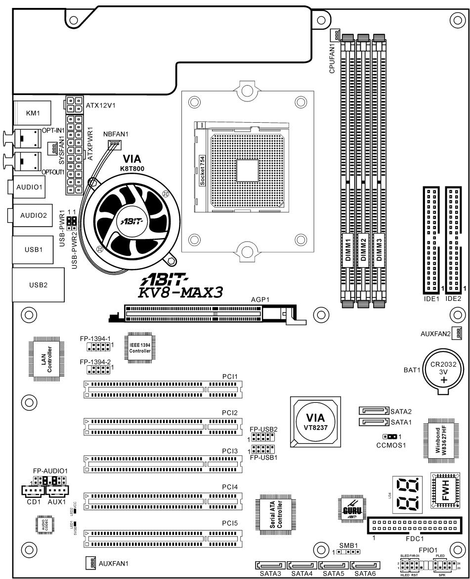
1-2. Layout Diagram

Chapter 2. Hardware Setup
Before the Installation: Turn off the power supply switch (fully turn off the +5V standby power), or disconnect the power cord before installing or unplugging any connectors or add-on cards. Failing to do so may cause the motherboard components or add-on cards to malfunction or damaged.
2-1. Install The Motherboard
Most computer chassis have a base with many mounting holes to allow motherboard to be securely attached on and at the same time, prevented from short circuits. There are two ways to attach the motherboard to the chassis base:
- use with studs
- or use with spacers
In principle, the best way to attach the board is to use with studs. Only if you are unable to do this should you attach the board with spacers. Line up the holes on the board with the mounting holes on the chassis. If the holes line up and there are screw holes, you can attach the board with studs. If the holes line up and there are only slots, you can only attach with spacers. Take the tip of the spacers and insert them into the slots. After doing this to all the slots, you can slide the board into
position aligned with slots. After the board has been positioned, check to make sure everything is OK before putting the chassis back on.

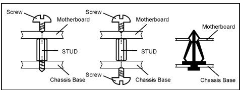
ATTENTION: To prevent shorting the PCB circuit, please REMOVE the metal studs or spacers if they are already fastened on the chassis base and are without mounting-holes on the motherboard to align with.
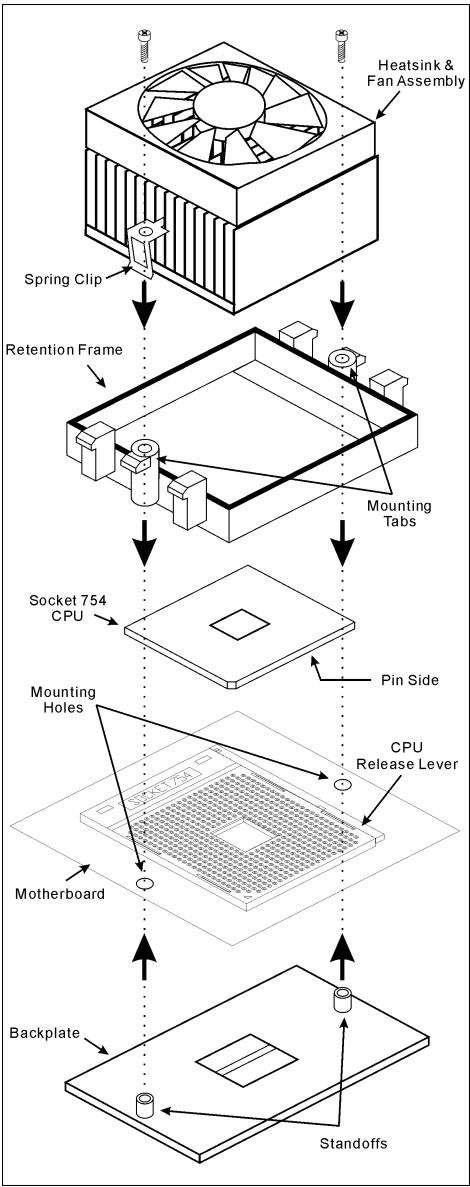
2-2. Install CPU and Heatsink
This motherboard provides a ZIF (Zero Insertion Force) Socket 754 to install AMD Socket 754 CPU. The CPU you bought should contain with a kit of heatsink, cooling fan, retention frame and blackplate. If that's not the case, buy one specially designed for Socket 754.
Please refer to the figure shown here to install CPU and heatsink. (For reference only. Your Heatsink & Fan Assembly may not be exactly the same as this one.)
- Locate the Socket 754 on this motherboard. Pull the CPU release lever sideways to unlatch and then raise it all the way up.
- Drop the processor with its pin side down into the CPU socket. Do not use extra force to insert CPU; it only fits in one direction. Close the CPU release lever.
- Align the Backplate Standoffs with the mounting holes on motherboard. Position the backplate onto motherboard.
- Place the Retention Frame onto the motherboard and align it with the Backplate Standoffs.
- Place heatsink on top of CPU, and make sure the heatsink fits properly on the retention frame.
- Hook both sides of the Spring Clip onto the Mounting Tabs of Retention Frame. Tighten screws until the Spring Clip is fully installed.
- Attach the fan connector of Heatsink & Fan Assembly with the CPU-FAN connector on the motherboard.
ATTENTION: Do not forget to set the correct bus frequency and multiple for your processor.
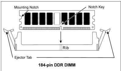
2-3. Install System Memory
This motherboard provides 3 184-pin DDR DIMM sites for memory expansion available from minimum 128MB to maximum 2GB.
Table 2-1. Valid Memory Configurations
| Bank | Memory Module | Total Memory |
| Bank 0, 1 (DIMM1) | 128, 256, 512MB, 1GB | 128MB ~ 1GB |
| Bank 2, 3 (DIMM2) | 128, 256, 512MB, 1GB | 128MB ~ 1GB |
| Bank 4, 5 (DIMM3) | 128, 256, 512MB, 1GB | 128MB ~ 1GB |
| Total System Memory | 128MB ~ 2GB | |
Table 2-2. AMD Athlon 64 Processor Memory Supporting sets
| DRAM number | DIMM1 | DIMM2 | DIMM3 | Memory spec |
| 2 | x8 single rank or x16 | x8 single rank or x16 | empty | DDR400 |
| 2 | x8 single rank or x16 | x8 double rank | empty | DDR400 |
| 2 | x8 single rank or x16 | empty | x8 single rank or x16 | DDR400 |
| 2 | x8 single rank or x16 | empty | x8 double rank | DDR400 |
| 2 | x8 double rank | x8 single rank or x16 | empty | DDR400 |
| 2 | x8 double rank | x8 double rank | empty | DDR400 |
| 2 | x8 double rank | empty | x8 single rank or x16 | DDR400 |
| 2 | empty | x8 single rank or x16 | x8 single rank or x16 | DDR333 |
| 3 | x8 double rank | x8 single rank or x16 | x8 single rank or x16 | DDR333 |
| 3 | x8 single rank or x16 | x8 single rank or x16 | x8 single rank or x16 | DDR333 |
Power off the computer and unplug the AC power cord before installing or removing memory modules.
- Locate the DIMM slot on the board.
- Hold two edges of the DIMM module carefully, keep away of touching its connectors.
- Align the notch key on the module with the rib on the slot.
- Firmly press the module into the slots until the ejector tabs at both sides of the slot automatically snaps into the mounting notch. Do not force the DIMM module in with extra force as the DIMM module only fit in one dire
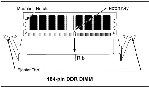
- To remove the DIMM modules, push the two ejector tabs on the slot outward simultaneously, and then pull out the DIMM module.
ATTENTION: Static electricity can damage the electronic components of the computer or optional boards. Before starting these procedures, ensure that you are discharged of static electricity by touching a grounded metal object briefly.
2-4. Connectors, Headers and Switches
Here we will show you all of the connectors, headers and switches, and how to connect them. Please read the entire section for necessary information before attempting to finish all the hardware installation inside the computer chassis. A complete enlarged layout diagram is shown in Chapter 1 for all the position of connectors and headers on the board that you may refer to.
WARNING: Always power off the computer and unplug the AC power cord before adding or removing any peripheral or component. Failing to so may cause severe damage to your motherboard and/or peripherals. Plug in the AC power cord only after you have carefully checked everything.
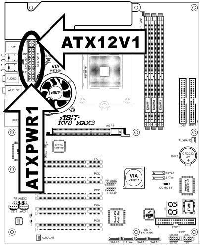
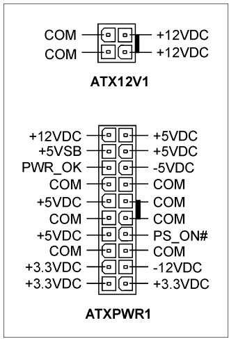
(1).ATX Power Input Connectors
This motherboard provides two power connectors to connect to an ATX12V power supply with 300W, 20A + 5VDC , and 720mA + 5VSB capacity at least.
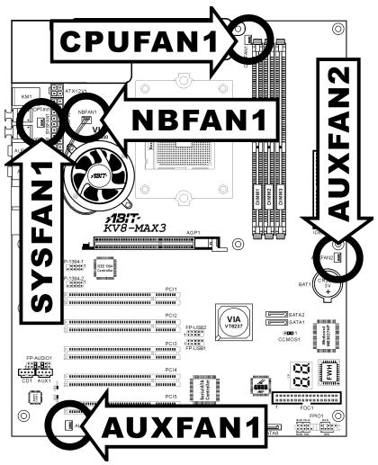
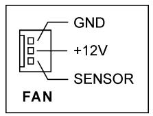
(2). FAN Connectors
These 3-pin connectors each provide power to the cooling fans installed in your system.
- CPUFAN1: CPU Fan
NBFAN1: Chipset Fan - SYSFAN1: OTES Fan
AUXFAN1,AUXFAN2:Auxiliary Fan
WARNING: These fan connectors are not jumpers. DO NOT place jumper caps on these connectors.
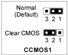
(3). CMOS Memory Clearing Header
This header uses a jumper cap to clear the CMOS memory.
Pin 1-2 shorted (default): Normal operation.
Pin 2-3 shorted: Clear CMOS memory.
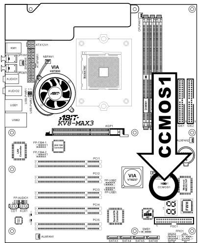
WARNING: Turn the power off first (including the +5V standby power) before clearing the CMOS memory. Failing to do so may cause your system to work abnormally or malfunction.
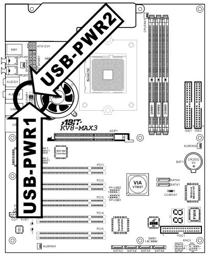
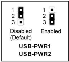
(4). Wake-up Header
These headers use a jumper cap to enable/disable the wake-up function.
USB-PWR1:
Pin 1-2 shorted (default): Disable wake-up function support at USB1 port.
Pin 2-3 shorted: Enable wake-up function support at USB1 port.
USB-PWR2:
Pin 1-2 shorted (default): Disable wake-up function support at USB2 port.
Pin 2-3 shorted: Enable wake-up function support at USB2 port.
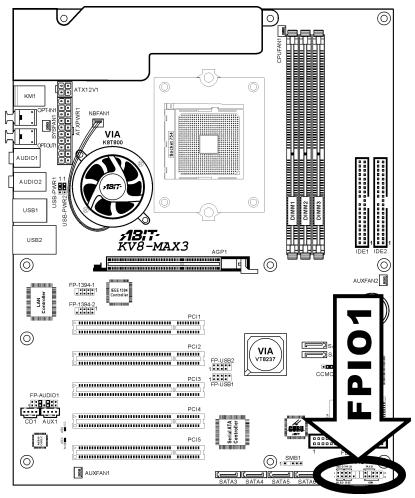
(5). Front Panel Switches & Indicators Headers
This header is used for connecting switches and LED indicators on the chassis front panel.
Watch the power LED pin position and orientation. The mark "+" align to the pin in the figure below stands for positive polarity for the LED connection. Please pay attention to connect these headers. A wrong orientation will only cause the LED not lighting, but a wrong connection of the switches could cause system malfunction.
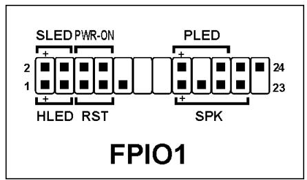
- HLED (Pin 1, 3): Connects to the HDD LED cable of chassis front panel.
RST (Pin 5,7): Connects to the Reset Switch cable of chassis front panel. - SPK (Pin 15, 17, 19, 21): Connects to the System Speaker cable of chassis.
- SLED (Pin 2, 4): Connects to the Suspend LED cable (if there is one) of chassis front panel.
- PWR-ON (Pin 6, 8): Connects to the Power Switch cable of chassis front panel.
- PLED (Pin 16, 18, 20): Connects to the Power LED cable of chassis front panel.
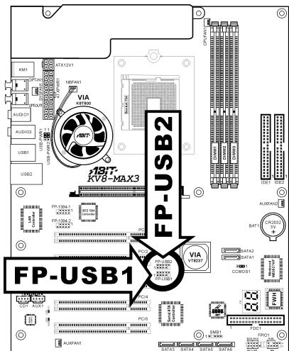
(6). Additional USB Port Headers
These headers each provide 2 additional USB 2.0 ports connection through an USB cable designed for USB 2.0 specifications.
| 2 4 6 8 10 ■ ▪ ▪ ▪ ▪ 1 3 5 7 9 FP-USB2 FP-USB1 | Pin | Pin Assignment | Pin | Pin Assignment |
| 1 | VCC | 2 | VCC | |
| 3 | Data0 - | 4 | Data1 - | |
| 5 | Data0 + | 6 | Data1 + | |
| 7 | Ground | 8 | Ground | |
| 9 | NC | 10 | NC |
(7). Additional IEEE1394 Port Header
These headers each provide one additional IEEE1394 port connection through an extension cable and bracket.
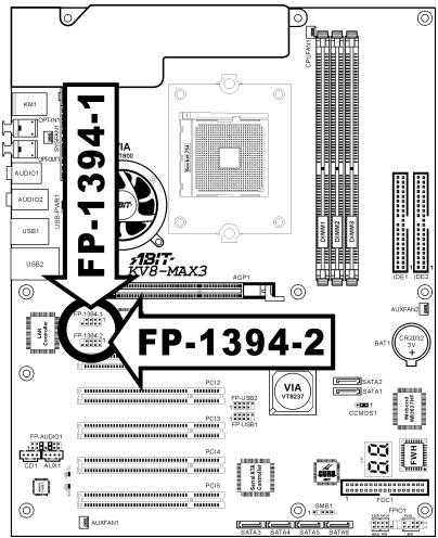
| 9 7 5 3 1 10 8 6 4 2 FP-1394-1 FP-1394-2 | Pin | Pin Assignment | Pin | Pin Assignment |
| 1 | TPA0 + | 2 | TPA0 - | |
| 3 | GND | 4 | GND | |
| 5 | TPB0 + | 6 | TPB0 - | |
| 7 | +12V | 8 | +12V | |
| 9 | NC | 10 | GND |
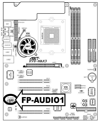
(8). Front Panel Audio Connection Header
This header provides the connection to audio connector at front panel.
- To use the audio connector at front panel, remove all the jumpers on this header, and then connect to front panel by the extension cable provided with the chassis.
- To use the audio connector at rear panel, disconnect the extension cable, attach the jumpers back at pin 5-6, and pin 9-10 (default setting).
| 2 4 6 8 10 12 14 1 3 5 7 9 11 13 FP-AUDIO1 | Pin | Pin Assignment | Pin | Pin Assignment |
| 1 | Audio Mic. | 2 | Ground | |
| 3 | Audio Mic. Bias | 4 | VCC | |
| 5 | Speaker Out Right Channel | 6 | Speaker Out Right Channel Return | |
| 7 | X | 8 | NC | |
| 9 | Speaker Out Left Channel | 10 | Speaker Out Left Channel Return | |
| 11 | Ground | 12 | S/PDIF In | |
| 13 | VCC | 14 | S/PDIF Out |
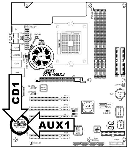
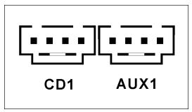
(9). Internal Audio Connectors
These connectors connect to the audio output of internal CD-ROM drive or add-on card.
(10). Accelerated Graphics Port Slot
This slot supports an optional AGP graphics card up to AGP 8X mode. Please refer to our Web site for more information on graphics cards.
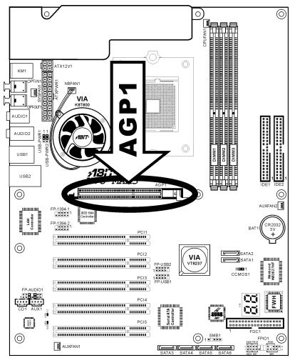
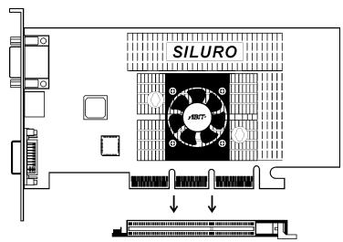
ATTENTION: This motherboard does not support 3.3V AGP cards. Use only 1.5V or 0.8V AGP cards.
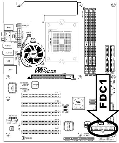
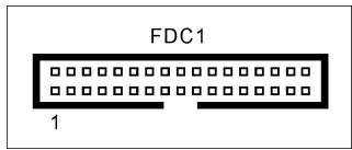
(11). Floppy Disk Drive Connector
This connector supports two standard floppy disk drives via a 34-pin 34-conductor ribbon cable.
Connecting the Floppy Disk Drive Cable:
- Install one end of the ribbon cable into the FDC1 connector. The colored edge of the ribbon cable should be aligned with pin-1 of FDC1 connector.
- Install the other end(s) of ribbon cable into the disk drive connector(s). The colored edge of the ribbon cable should be also aligned with pin-1 of disk drive connector. The endmost connector should be attached to the drive designated as Drive A.
(12). IDE Connectors
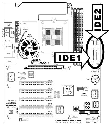
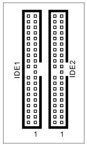
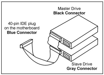
This motherboard provides two IDE ports to connect up to four IDE drives at Ultra DMA mode by Ultra ATA/66 ribbon cables. Each cable has 40-pin 80-conductor and three connectors, providing two hard drives connection with motherboard. Connect the single end (blue connector) at the longer length of ribbon cable to the IDE port on motherboard, and the other two ends (gray and black connector) at the shorter length of the ribbon cable to the connectors on hard drives.
If you want to connect two hard drives together through one IDE channel, you must configure the second drive to Slave mode after the first Master drive. Please refer to the drives' documentation for jumper settings. The first drive connected to IDE1 is usually referred to as "Primary Master", and the second drive as "Primary Slave". The first drive connected to IDE2 is referred to as "Secondary Master" and the second drive as "Secondary Slave".
Keep away from connecting one legacy slow speed drive, like CD-ROM, together with another hard drive on the same IDE channel; this will drop your integral system performance.
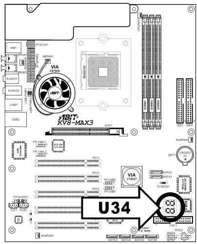
(13). POST Code Display
This is an LED device to display the "POST" Code, the acronym of Power On Self Test. The computer will execute the POST action whenever you power on the computer. The POST process is controlled by the BIOS. It is used to detect the status of the computer's main components and peripherals. Each POST Code corresponds to different checkpoints that are also defined by the BIOS in advance. For example, "memory presence test" is an important checkpoint and its POST Code is "C1". When the BIOS execute any POST item, it will write the corresponding POST Code into the address 80h. If the POST passes, the BIOS will process the next POST item and write the next POST Code into the address 80h. If the POST fails, we can check the POST Code in address 80h to find out where the problem lies.
This LED device also displays the "POST" Code of AC2003, an "uGuru" chipset developed exclusively by ABIT computer.
NOTE: The decimal point lights up when executing the AC2003 POST action.

See Appendix for both AWARD and AC2003 POST Code definition.
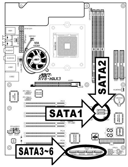
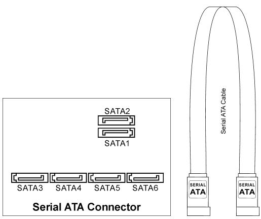
(14). Serial ATA Connectors
These connectors are provided to attach one Serial ATA device at each channel via Serial ATA cable.
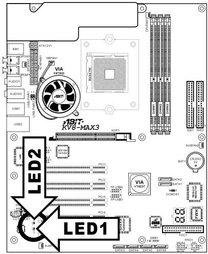
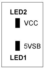
(15). Status Indicators
- LED1 (5VSB): This LED lights up when the power supply is connected with power source.
LED2 (VCC): This LED lights up when the system power is on.
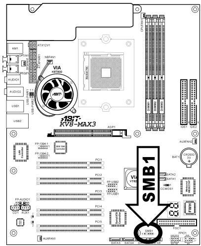
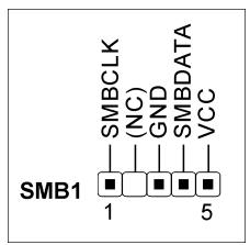
(16). System Management Bus Headers
This header is reserved for system management bus (SM bus). The SM bus is a specific implementation of an I^2C bus. I^2C is a multi-master bus, which means that multiple chips can be connected to the same bus and each one can act as a master by initiating a data transfer. If more than one master simultaneously tries to control the bus, an arbitration procedure decides which master gets priority.
(17). Back Panel Connectors
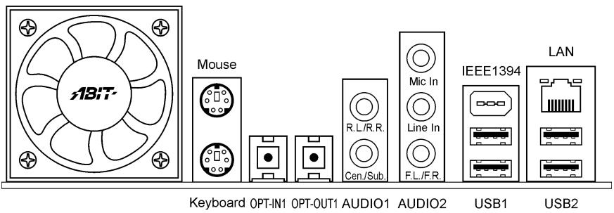
- Mouse: Connects to PS/2 mouse.
Keyboard: Connects to PS/2 keyboard. - OPT-IN1: This connector provides an S/PDIF in connection through optical fiber to digital multimedia devices.
- OPT-OUT1: This connector provides an S/PDIF out connection through optical fiber to digital multimedia devices.
AUDIO1:
R.L./R.R. (Rear Left / Rear Right): Connects to the rear left and rear right channel in the 5.1 channel audio system.
Cen./Sub. (Center / Subwoofer): Connects to the center and subwoofer channel in the 5.1 channel audio system.
AUDIO2:
Mic In: Connects to the plug from external microphone.
Line In: Connects to the line out from external audio sources.
F.L./F.R. (Front Left / Front Right): Connects to the front left and front right channel in the 5.1-channel or regular 2-channel audio system.
- IEEE1394: Connects to devices of IEEE1394 protocol.
- LAN: Connects to Local Area Network.
- USB1/USB2: Connects to USB devices such as scanner, digital speakers, monitor, mouse, keyboard, hub, digital camera, joystick etc.
Chapter 3. BIOS Setup
This motherboard provides a programmable EEPROM that you can update the BIOS utility. The BIOS (Basic Input/Output System) is a program that deals with the basic level of communication between processor and peripherals. Use the BIOS Setup program only when installing motherboard, reconfiguring system, or prompted to "Run Setup". This chapter explains the Setup Utility of BIOS utility.
After powering up the system, the BIOS message appears on the screen, the memory count begins, and then the following message appears on the screen:
PRESS DEL TO ENTER SETUP
If this message disappears before you respond, restart the system by pressing <Ctrl> + <Alt> + <Del> keys, or by pressing the Reset button on computer chassis. Only when it failed by these two methods can you restart the system by powering it off and then back on.
After pressing <Del> key, the main menu screen appears.
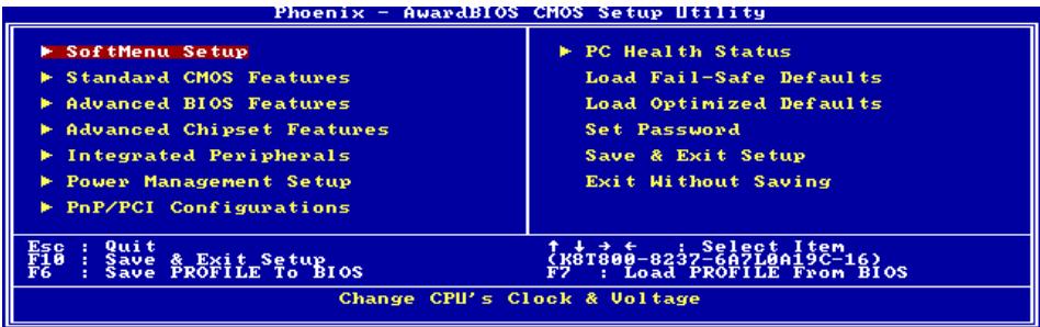
NOTE: In order to increase system stability and performance, our engineering staffs are constantly improving the BIOS menu. The BIOS setup screens and descriptions illustrated in this manual are for your reference only, may not completely match what you see on your screen.
In the BIOS Setup main menu, you can see several options. We will explain these options step by step in the following pages of this chapter, but let us first see a short description of the function keys you may use here.
Esc:
Press this button to quit the BIOS Setup.

Press these buttons to choose, in the main menu, the option you want to confirm or to modify.
F10:
When you have completed the setup of BIOS parameters, press this button to save these parameters and to exit the BIOS Setup menu.
F6:
You may create a profile to save the new BIOS settings in it. Press
Save Profile To BIOS (Y/N)?
After pressing "Y", the following message will appear to assist you in creating a name for the profile.
Enter Profile Name:
Type the profile name, and press
NOTE: You may save up to five profiles to BIOS.
F7:
Press <F7> button in the main menu, a dialog box with five numbers (1 5) will appear on the screen. Select the profile you want, and press <Enter> . Then, you will get a confirmation dialog box with a message similar to:
Load Profile From BIOS (Y/N)?
Press "Y" to load the BIOS settings in this profile.
3-1. SoftMenu Setup
The SoftMenu utility is ABIT's exclusive and ultimate solution in programming the CPU operating speed. All the parameters regarding CPU FSB speed, multiplier factor, the AGP & PCI clock, and even the CPU core voltage are all available at your fingertips.
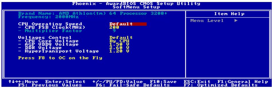
Brand Name:
This item displays the CPU model name, for example: AMD Athlon(tm) 64 Processor 3200+ .
Frequency:
This item displays the processor speed.
CPU Operating Speed:
This item displays the CPU operating speed according to the type and speed of your CPU. You can also select the [User Define] option to enter the manual option.
User Define:
WARNING: The wrong settings of the multiplier and external clock in certain circumstances may cause CPU damage. Setting the working frequency higher than the PCI chipset or processor specs, may cause abnormal memory module functioning, system hangs, hard disk drive data lose, abnormal functioning of the VGA card, or abnormal functioning with other add-on cards. Using non-specification settings for your CPU is not the intention of this explanation. These should be used for engineering testing, not for normal applications.
There will be no guaranty for the settings beyond specification, any damage of any component on this motherboard or peripherals result therein is not our responsibility.
※ CPUFSB Clock (MHz):
This item sets the CPU Front Side Bus speed from 200 to 300. Due to the specification limit of the CPU you installed, the speed you set over its standard bus speed is supported, but not guaranteed.
\* Multiplier Factor:
This item displays the multiplier factor for the CPU you installed.
NOTE: Some processors might have this multiplier factor locked, so there is no way to choose a higher multiplier factor.
Voltages Control:
This option allows you to switch between the default and user-defined voltages. Leave this setting to default unless the current voltage setting cannot be detected or is not correct. The option "User Define" enables you to select the following voltages manually.
* CPU Core Voltage:
This item selects the CPU core voltage.
- AGP VDDQ Voltage:
This item selects the voltage for AGP slot.
- DDR Voltage:
This item selects the voltage for DRAM slot.
HyperTransport Voltage:
This item selects the voltage for LDT Bus.
Press F8 to OC on the Fly:
After a new configuration on items "CPU FSB Clock (MHz)" and "Voltage", pressing <F8> button now in this menu will make it become effective immediately.
ATTENTION: An external clock too much over its specification may cause the system unstable or even fail, please proceed with highly attention.
3-2. Standard CMOS Features
This section contains the basic configuration parameters of the BIOS. These parameters include date, hour, VGA card, FDD and HDD settings.
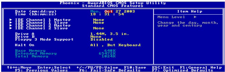
Date (mm:dd:vv):
This item sets the date you specify (usually the current date) in the format of [Month], [Date], and [Year].
Time (hh:mm:ss):
This item sets the time you specify (usually the current time) in the format of [Hour], [Minute], and [Second].
IDE Channel 1 Master / Slave, IDE Channel 2 Master / Slave:
Click
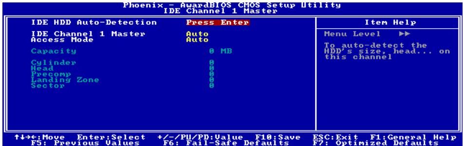
IDE HDD Auto-Detection:
This item allows you to detect the parameters of IDE drives by pressing
IDE Channel 1 Master / Slave, IDE Channel 2 Master / Slave:
When set to [Auto], the BIOS will automatically check what kind of IDE drive you are using. If you want to define your own drive by yourself, set it to [Manual] and make sure you fully understand the meaning of the parameters. Please refer to the instruction manual provided by the device's manufacturer to get the setting right.
Access Mode:
This item selects the mode to access your IDE devices. Leave this item to its default [Auto] setting to detect the access mode of your HDD automatically.
Capacity:
This item displays the approximate capacity of the disk drive. Usually the size is slightly greater than the size of a formatted disk given by a disk-checking program.
Cylinder:
This item configures the numbers of cylinders.
Head:
This item configures the numbers of read/write heads.
Precomp:
This item displays the number of cylinders at which to change the write timing.
Landing Zone:
This item displays the number of cylinders specified as the landing zone for the read/write heads.
Sector:
This item configures the numbers of sectors per track.

Back to Standard CMOS Features Setup Menu:
Drive A & Drive B:
This item sets the type of floppy drives (usually only Drive A) installed.
Floppy 3 Mode Support:
This item allows you to use "3 Mode Floppy Drive" in Japanese computer system by selecting drive A, B, or both. Leave this item to its default [Disabled] setting if you are not using this Japanese standard floppy drive.
Halt On:
This item determines whether the system stops if an error is detected during system boot-up.
[All Errors]: The system-boot will stop whenever the BIOS detect a non-fatal error.
[No Errors]: The system-boot will not stop for any error detected.
[All, But Keyboard]: The system-boot will stop for all errors except a keyboard error.
[All, But Diskette]: The system-boot will stop for all errors except a diskette error.
[All, But Disk/Key]: The system-boot will stop for all errors except a diskette or keyboard error.
Base Memory:
This item displays the amount of base memory installed in the system. The value of the base memory is typically 640K for system with 640K or more memory size installed on the motherboard.
Extended Memory:
This item displays the amount of extended memory detected during system boot-up.
Total Memory:
This item displays the total memory available in the system.
3-3. Advanced BIOS Features
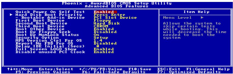
Quick Power On Self Test:
When set to [Enabled], this item speeds up the Power On Self Test (POST) after powering on the system. The BIOS shorten or skip some check during the POST.
Hard Disk Boot Priority:
This item selects the hard disks booting priority. By pressing
This item functions only when there is the option of [Hard Disk] in any one of the First/Second/Third Boot Device items.
* Bootable Add-in Device:
This item allows you to select the add-in device priority among the [PCI Slot Device], [Onchip SATA RAID], and [Onboard SATA RAID]. Onchip SATA RAID means VIA SATA RAID. Onboard SATA RAID means SIL3114 SATA RAID.
First Boot Device / Second Boot Device / Third Boot Device / Boot Other Device:
Select the drive to boot first, second and third in the [First Boot Device], [Second Boot Device], and [Third Boot Device] items respectively. The BIOS will boot the operating system according to the sequence of the drive selected. Set [Boot Other Device] to [Enabled] if you wish to boot from another device other than these three items.
Boot Up Floppy Seek:
When set to [Enabled], the BIOS will check whether the floppy disk drive is installed or not.
Boot Up NumLock Status:
This item determines the default state of the numeric keypad at system booting up.
[On]: The numeric keypad functions as number keys.
[Off]: The numeric keypad functions as arrow keys.
Security Option:
This item determines when the system will prompt for password - every time the system boots or only when enters the BIOS setup.
[Setup]: The password is required only when accessing the BIOS Setup.
[System]: The password is required each time the computer boots up.
NOTE: Don't forget your password. If you forget the password, you will have to open the computer case and clear all information in the CMOS before you can start up the system. But by doing this, you will have to reset all previously set options.
MPS Version Ctrl For OS:
This item specifies which version of MPS (Multi-Processor Specification) this motherboard will use. The options are 1.1 and 1.4. The default setting is 1.4. If you use an older OS for dual processor executing, please set this option to 1.1.
Report No FDD For OS:
When set to [Enabled], this item allows you to run some older operating system without floppy disk drive. Leave this item to its default setting.
Delav IDE Initial (Secs):
This item allows the BIOS to support some old or special IDE devices by prolonging this delay time. A larger value will give more delay time to the device for which to initialize and to prepare for activation.
Full Screen LOGO Show:
This item determines to show the full screen logo when booting.
Disable unused PCI Clock:
This option disables the clock of PCI slot that is not in use.
[Enabled]: The system automatically detect the unused PCI slots, and stop sending clock signal to these unused PCI slots.
[Disabled]: The system always send clock signal to all PCI slots.
NOTE: Set this option to [Disabled] setting if there are adapters that cannot be automatically detected by the system and will cause malfunction.
3-4. Advanced Chipset Features
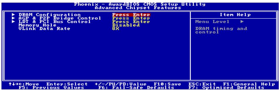
DRAM Configuration:
Click
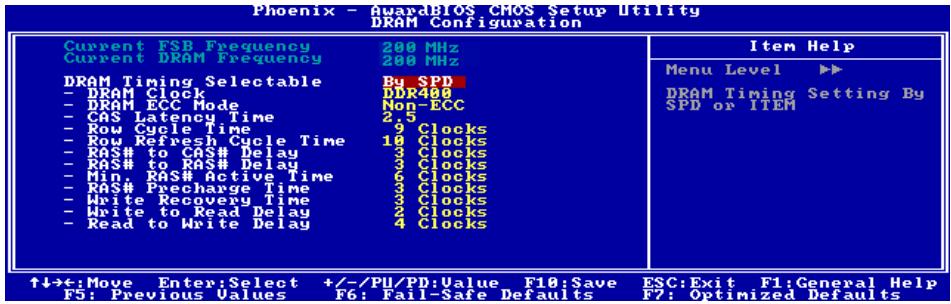
Current FSB Frequency:
This item will show you the current system front side bus speed.
Current DRAM Frequency:
This item will show you the current DRAM bus speed.
DRAM Timing Selectable:
Two options are available: Manual By SPD. The default setting is BySPD . When set to "By SPD", the BIOS will read the DRAM module SPD data and automatically set to the values stored in it.
* DRAM Clock:
This item sets the DRAM clock of your DRAM module. The system may be unstable or unable to boot up if your DRAM module does not support the clock you set.
When set to [By SPD], the BIOS will read the DRAM module SPD data and automatically set the DRAM clock by the value stored in it.
- DRAM ECC Mode:
When set to [ECC], your DRAM module will support the ECC Mode.
* CAS Latency Time:
Three options are available: 2 2.5 3 . The default setting is 2.5. You can select SDRAM CAS (Column Address Strobe) latency time according to your SDRAM specification.
- Row Cycle Time:
This item specifies the RAS# active to RAS# active time or auto refresh time of the same bank.
Row Refresh Cycle Time:
This item specifies the auto refresh active to RAS# active time or RAS# auto refresh time.
※ RAS# to CAS# Delay:
This item specifies the RAS# active to CAS# read write delay time to the same bank.
※ RAS# to RAS# Delay:
This item specifies the RAS# active to RAS# active delay time of different bank.
- Min. RAS# Active Time:
This item specifies the minimum RAS# active time.
※ RAS# Precharge Time:
This item specifies the RAS# precharge time.
* Write Recovery Time:
This item specifies the time measured from the last write datum is safely registered by the DRAM.
* Write to Read Delay:
This item specifies the time measured from the rising edge following the last non-masked data strobe to the rising edge of the next read command.
* Read to Write Delay:
This item specifies the read to write delay.

Back to Advanced Chipset Features Setup Menu:
AGP & P2P Bridge Control:
Click
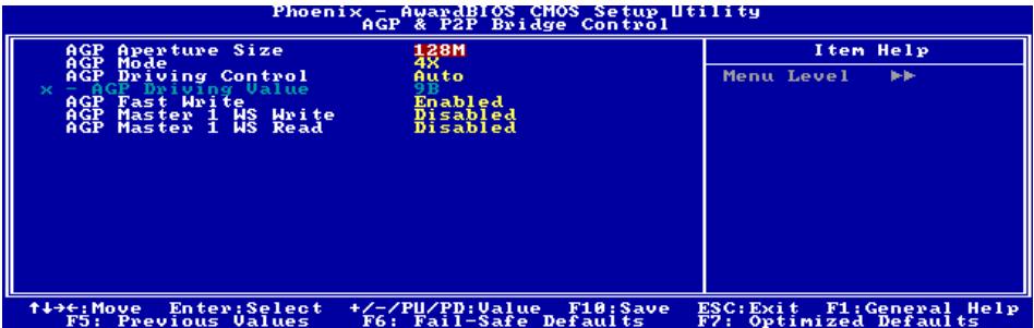
AGP Aperture Size:
This option specifies the amount of system memory that can be used by the AGP device. The aperture is a portion of the PCI memory address range dedicated for graphics memory address space.
AGP Mode:
This item selects the data transfer rate of AGP device. A higher rate delivers faster and better graphics to your system. Make sure your graphics card supports the mode you select.
AGP Driving Control:
Leave this item to its default setting.
* AGP Driving Value:
Leave this item to its default setting.
AGP Fast Write:
Two options are available: Disabled Enabled. The default setting is Enabled. If your AGP adapter can support this function, then you can choose Enabled. Otherwise, choose Disabled.
AGP Master 1 WS Write:
Two options are available: Disabled Enabled. The default setting is Disabled. This implements a single delay when writing to the AGP Bus. When you set it to Enabled, two-wait states are used by the system, allowing for greater stability.
AGP Master 1 WS Read:
Two options are available: Disabled Enabled. The default setting is Disabled. This implements a single delay when reading to the AGP Bus. When you set it to Enabled, two-wait states are used by the system, allowing for greater stability.

Back to Advanced Chipset Features Setup Menu:
LDT & PCI Bus Control:
Click
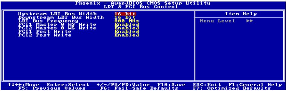
Upstream/Downstream LDT Bus Width:
This item allows you to select LDT Bus Width.
LDT Bus Frequency:
This item allows you to select LDT Bus Frequency.
PCI1/PCI2 Master 0 WS Write:
Two options are available: Enabled or Disabled. The default setting is Enabled. When Enabled, writes to the PCI bus are executed with zero wait state (immediately) when PCI bus is ready to receive data. If it is set to Disabled, the system will wait one state before data is written to the PCI bus.
PCI1/PCI2 Post Write:
Two options are available: Enabled or Disabled. The default is Enabled, When Enabled, data transmission from CPU to PCI bus are buffered and compensate for the different speed between CPU and PCI bus. If it is set to Disabled, data transmissions are not buffered and CPU must wait until the data transmission is complete and then start another transmission cycle.

Back to Advanced Chipset Features Setup Menu:
Memory Hole:
When set to [15M-16M], the memory address space at 15M-16M will be reserved for ISA expansion cards that specifically requires this setting. This makes the memory from 15MB and up unavailable to the system. Leave this item to its default setting.
Vlink Data Rate:
This item can let you select the Vlink Data Rate between northbridge and southbridge.
3-5. Integrated Peripherals
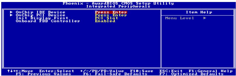
OnChip IDE Device:
Click
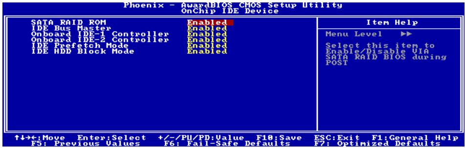
SATA RAID ROM:
This item allows you to use the boot ROM of on-chip Serial ATA RAID to boot-up system.
IDE Bus Master:
This option enables or disables the IDE bus mastering capability under the DOS environment.
Onboard IDE-1/IDE-2 Controller:
This item allows you to enable or disable the primary and secondary IDE controller. Select [Disabled] if you want to add a different hard drive controller.
IDE Prefetch Mode:
Two options are available: Disabled or Enabled. The default setting is Enabled. The onboard IDE drive interfaces supports IDE prefetching for faster drive accesses. If you install a primary and/or secondary add-in IDE interface, set this field to Disabled if the interface does not support prefetching.
IDE HDD Block Mode:
This option enables or disables the IDE HDD block mode.

Back to Integrated Peripherals Setup Menu:
OnChip PCI Device:
Click
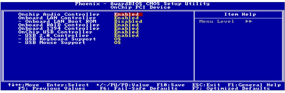
OnChip Audio Controller:
This option enables or disables the audio controller.
Onboard LAN Controller:
This option enables or disables the LAN controller.
Onboard LAN Boot ROM:
This item enables or disables the Boot ROM on LAN controller.
Onboard RAID Controller:
This option enables or disables the SIL3114 SATA RAID controller.
Onboard 1394 Controller:
This option enables or disables the onboard IEEE 1394 controller.
OnChip USB Controller:
This option enables or disables the USB controller.
\* USB 2.0 Controller:
This option enables or disables the USB 2.0 controller.
\* USB Keyboard Support:
This item allows you to select [BIOS] for using USB keyboard in DOS environment, or [OS] in OS environment.
\* USB Mouse Support:
This item allows you to select [BIOS] for using USB mouse in DOS environment, or [OS] in OS environment.
Back to Integrated Peripherals Setup Menu:
Init Display First:
This item selects to initialize AGP or PCI Slot first when the system boots.
[PCI Slot]: When the system boots, it will first initialize PCI.
[AGP]: When the system boots, it will first initialize AGP.
Onboard FDD Controller:
Two options are available: Enabled and Disabled. The default setting is Enabled. You can enable or disable the onboard FDD controller.
3-6. Power Management Setup
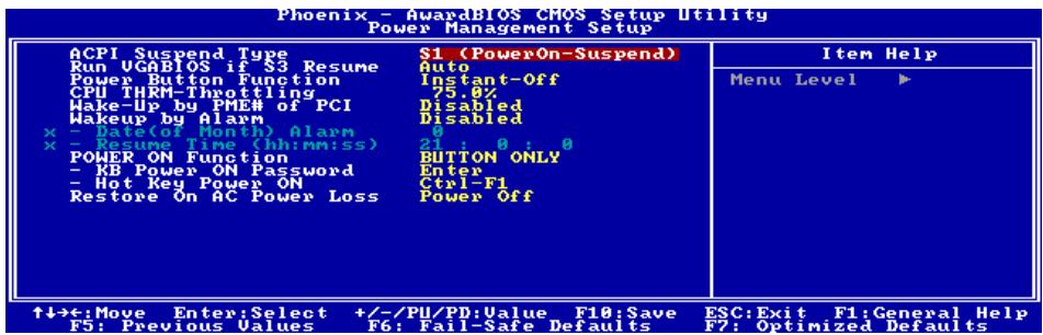
ACPI Suspend Type:
This item selects the type of Suspend mode.
[S1(PowerOn-Suspend)]: Enables the Power On Suspend function.
[S3(Suspend-To-RAM)]: Enables the Suspend to RAM function.
Run VGABIOS if S3 Resume:
Three options are available: Auto Yes No. The default setting is Auto. This item can let you choose when S3 resume active, the VGA BIOS need to be initiative or not.
Power Button Function:
This item selects the method of powering off your system:
[Delay 4 Sec.]: Pushing the power button for more than 4 seconds will power off the system. This will prevent the system from powering off in case you accidentally hit or pushed the power button.
[Instant-Off]: Pressing and then releasing the power button at once will immediately power off the system.
CPU THRM-Throttling:
This item controls the CPU speed by cutting down its regular power to a percentage during the STR (Suspend To RAM) state.
Wakeup by PME# of PCI:
Two options are available: Disabled or Enabled. The default setting is Disabled. When set to Enabled, any event affecting from PCI card (PME) will awaken a system that has powered down.
Wakeup by Alarm:
Two options are available: Disabled or Enabled. The default setting is Disabled. When set to Enabled, you can set the date and time at which the RTC (real-time clock) alarm awakens the system from Suspend mode.
* Date (of Month) Alarm / Resume Time (hh:mm:ss):
You can set the Date (month) Alarm and Time Alarm (hh:mm:ss). Any event occurring will awaken a system that has powered down.
POWER ON Function:
This item selects the way you want your system to power on.
[Password]: Use a password to power on the system, select this option then press
[Hot KEY]: Use any of the function keys between <F1> to <F12> to power on the system.
[Mouse Left]: Double click the mouse left button to power on the system.
[Mouse Right]: Double click the mouse right button to power on the system.
[Any KEY]: Use any keyboard keys to power on the system.
[BUTION ONLY]: Use only the power button to power on the system.
[Keyboard 98]: Use the power-on button on the "Keyboard 98" compatible keyboard to power on the system.
NOTE: The mouse wake up function can only be used with the PS/2 mouse, not with the COM port or USB type. Some PS/2 mice cannot wake up the system because of compatible problems. If the specs of your keyboard are too old, it may fail to power on.
\* KB Power ON Password:
This item sets the password required in order to power on your computer.
NOTE: Do not forget your password, or you will have to clear the CMOS and reset all parameters in order to utilize this function again.
Hot Key Power ON:
This item powers on the system by pressing Ctrl key plus one of each function key ( F1 F12 ) simultaneously.
Restore On AC Power Loss:
This item selects the system action after an AC power failure.
[Power Off]: When power returns after an AC power failure, the system's power remains off. You must press the Power button to power-on the system.
[Power On]: When power returns after an AC power failure, the system's power will be powered on automatically.
[Last State]: When power returns after an AC power failure, the system will return to the state where you left off before power failure occurs. If the system's power is off when AC power failure occurs, it will remain off when power returns. If the system's power is on when AC power failure occurs, the system will power-on when power returns.
3-7. PnP/PCI Configurations
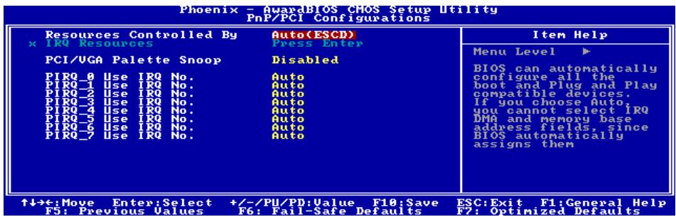
Resources Controlled By:
This item configures all of the boot and Plug-and-Play compatible devices.
[Auto(ESCD)]: The system will automatically detect the settings.
[Manual]: Choose the specific IRQ resources in the "IRQ Resources" menu.
* IRQ Resources:
Click
This item sets each system interrupt to either [PCI Device] or [Reserved].
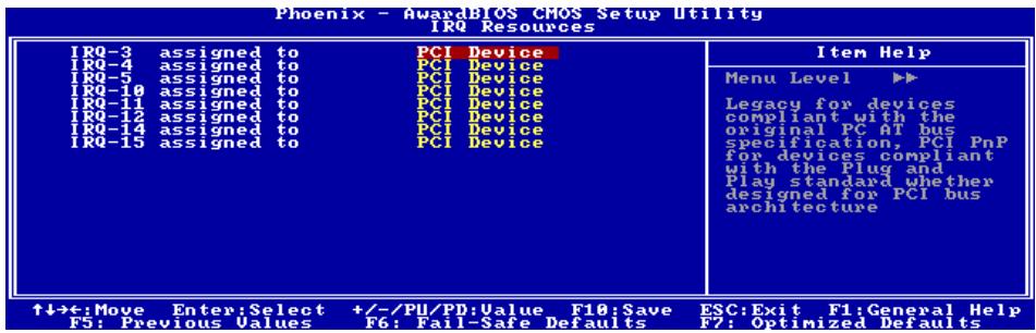
Back to PnP/PCI Configurations Setup Menu:
PCI/VGA Palette Snoop:
This item determines whether the MPEG ISA/VESA VGA cards can work with PCI/VGA or not.
[Enabled]: MPEG ISA/VESA VGA cards work with PCI/VGA.
[Disabled]: MPEG ISA/VESA VGA cards do not work with PCI/VGA.
PIRQ 0 Use IRQ No.~PIRQ 7 Use IRQ No.:
This item specifies the IRQ number manually or automatically for the devices installed on PCI slots.
For the relations between the hardware layout of PIRQ (the signals from the VIA VT8237 chipset), INT# (means PCI slot IRQ signals) and devices, please refer to the table below:
| Signals | AGP | LAN | PCI-1 | PCI-2 | PCI-3 | PCI-4 | PCI-5 | SATA | 1394 |
| PIRQ_0 Assignment | INT A | INT A | INT B | INT C | INT D | ||||
| PIRQ_1 Assignment | INT B | INT B | INT C | INT D | INT A | ||||
| PIRQ_2 Assignment | INT C | INT D | INT A | INT B | |||||
| PIRQ_3 Assignment | INT D | INT A | INT B | INT C | |||||
| PIRQ_4 Assignment | INT G | INT E | INT F | INT H | |||||
| PIRQ_5 Assignment | INT F | ||||||||
| PIRQ_6 Assignment | INT G | ||||||||
| PIRQ_7 Assignment | INT H |
NOTE:
PCI slot 1 shares IRQ signals with AGP slot.
- If you want to install two PCI cards into those PCI slots that share IRQ with one another at the same time, you must make sure that your OS and PCI devices' driver supports the IRQ sharing function.
3-8. PC Health Status
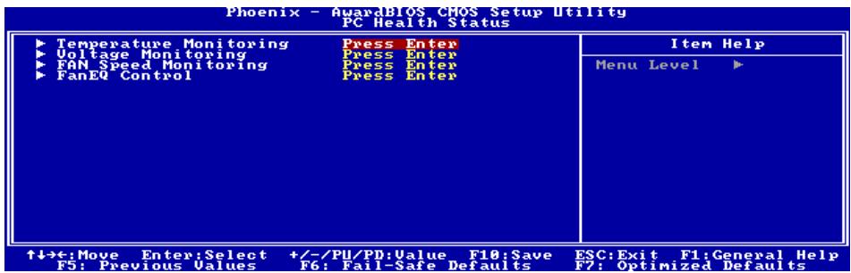
Temperature Monitoring:
Click
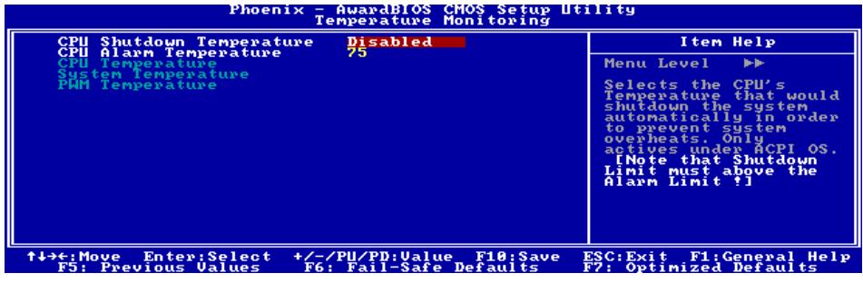
CPU Shutdown Temperature:
This item sets the temperature that would shutdown the system automatically in order to prevent system overheats.
NOTE: The CPU shutdown temperature limit must be higher than the CPU alarm temperature limit.
CPU Alarm Temperature:
This item selects the CPU's warning temperature limit. Once the system has detected that the CPU's temperature exceeded the limit, warning beeps will sound.
CPU Temperature/System Temperature/PWM Temperature:
These items display the temperature of CPU, System, and Power Module.

Voltage Monitoring:
Click
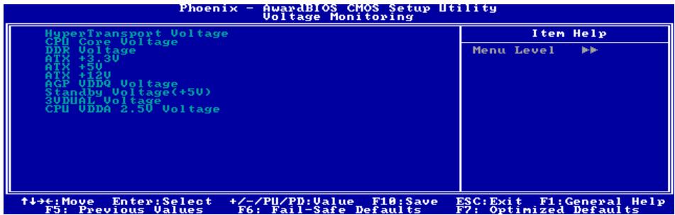
These items display the voltage of each element.

FAN Speed Monitoring:
Click
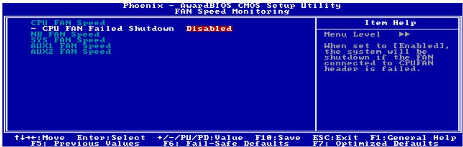
CPU/NB/SYS/AUX1/AUX2 FAN Speed:
These items display the speed of the fans connected to CPU, NB, SYS, AUX1 and AUX2 FAN headers.
\* CPU FAN Failed Shutdown
When set to [Enabled], the system will be shut down if the fan connected to CPUFAN header is failed.
NOTE:
- Only the fans with 3-pin plugs provide the speed monitoring function.
- The OTES fan connector is attached with the SYSTEM1 fan connector on the motherboard. Therefore, the SYS FAN Speed displayed here represents the OTES fan speed.

FanEQ Control:
Click
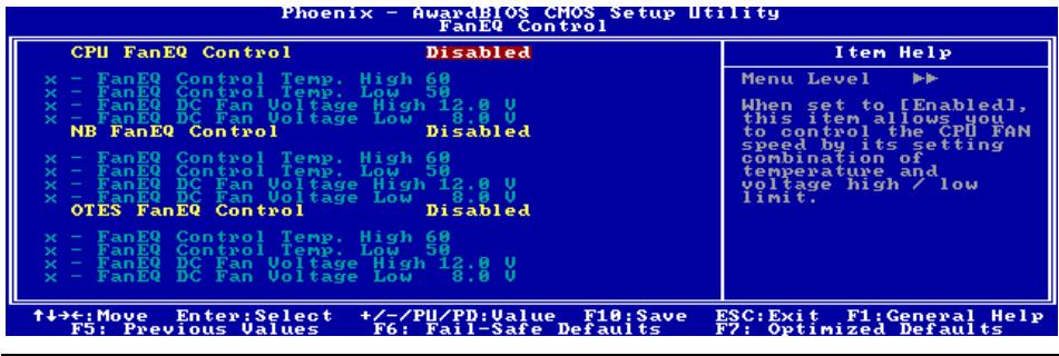
CPU FanEQ Control:
When set to [Enabled], this item allows you to control the CPU fan speed by its setting combination of temperature and voltage high/low limit.
FanEQ Control Temp. High/Low
This item sets the high and low temperature limit that you want to do the fan speed control.
- FanEQ DC Fan Voltage High/Low
This item sets the high and low voltage limit that you want to provide the fan with.
NOTE: The value of high limit must be higher than the value of low limit.
NB FanEQ Control:
When set to [Enabled], this item allows you to control the NB fan speed by its setting combination of temperature and voltage high/low limit.
FanEQ Control Temp. High/Low
This item sets the high and low temperature limit that you want to do the fan speed control.
FanEQ DC Fan Voltage High/Low
This item sets the high and low voltage limit that you want to provide the fan with.
NOTE: The value of high limit must be higher than the value of low limit.
OTES FanEQ Control:
When set to [Enabled], this item allows you to control the OTES fan speed by its setting combination of temperature and voltage high/low limit.
FanEQ Control Temp. High/Low
This item sets the high and low temperature limit that you want to do the fan speed control.
FanEQ DC Fan Voltage High/Low
This item sets the high and low voltage limit that you want to provide the fan with.
NOTE: The value of high limit must be higher than the value of low limit.
3-9. Load Fail-Safe Defaults
This option loads the BIOS default values for the most stable, minimal-performance system operations.
3-10. Load Optimized Defaults
This option loads the BIOS default values that are factory settings for optimal-performance system operations.
3-11. Set Password
This option protects the BIOS configuration or restricts access to the computer itself.
3-12. Save & Exit Setup
This option saves your selections and exits the BIOS setup menu.
3-13. Exit Without Saving
This option exits the BIOS setup menu without saving any change.
Appendix A. Install VIA 4-in-1 Driver
NOTE: Please install this VIA 4-in-1 driver first after having installed the Windows operating system.
The installation procedures and screen shots in this section are based on Windows XP operating system. For those of other OS, please follow its on-screen instruction.
Insert the Driver & Utility CD into CD-ROM drive, it should execute the installation program automatically. If not, double-click the execution file at the main directory of this CD to enter the installation menu.
After entering the installation menu, move your cursor to [Drivers] tab. Click [VIA 4in1 Driver]. The following screen appears.
1. Click [Next].
![ABIT KV8-MAX3 - Click [Next]. - 1](/content/2025/01/174567/images/7540c36fcf056562fcfcca7dae3f73be181f88f4a145a568485691c51c2063ad.jpg)
2. Click [Yes].
![ABIT KV8-MAX3 - Click [Yes]. - 1](/content/2025/01/174567/images/43eb9427d984f9d998c0fd3c2eb722939970b43651799ad3be6bceaafdb05f4b.jpg)
3. Click [Next].
![ABIT KV8-MAX3 - Click [Next]. - 1](/content/2025/01/174567/images/1d5fefca28c2cbef0b722fe54e36d704ab4108c7a6bf1f4e17479a70fbfd0f6e.jpg)
4. Click [Next].
![ABIT KV8-MAX3 - Click [Next]. - 1](/content/2025/01/174567/images/dbe3bc5e3b258fe219b50bc0a7a84993bbb23f25f173bf80a7c3b0e31efb6a1c.jpg)
5. Click [Next].
![ABIT KV8-MAX3 - Click [Next]. - 1](/content/2025/01/174567/images/6f0560f5cce2a41077684c815937730d0856a6a28cd8c4391bfc07c9ce8a81b4.jpg)
- Click [Next].
![ABIT KV8-MAX3 - Click [Next]. - 2](/content/2025/01/174567/images/87cf4670b002e27f310bee5e45d3d03fa3b662643a0d79d0bd9fdd8b1253657a.jpg)
- Choose [Yes, I want to restart my computer now.], and click [OK] to complete setup.
Appendix B. Install Audio Driver
The installation procedures and screen shots in this section are based on Windows XP operating system. For those of other OS, please follow its on-screen instruction.
Insert the Driver & Utility CD into CD-ROM drive, it should execute the installation program automatically. If not, double-click the execution file at the main directory of this CD to enter the installation menu.
After entering the installation menu, move your curser to [Drivers] tab. Click [Audio Driver]. The following screen appears.
- Click [Next].
- Choose [Yes, I want to restart my computer now.], and click [Finish] to complete setup.
- After the system restarted, a shortcut icon appears at the right corner of Windows task bar.
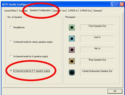
- In this Speaker Configuration tab, select [6 channels mode for 5.1 speakers output] to enable 6-channel audio system

Appendix C. Install LAN Driver
The installation procedures and screen shots in this section are based on Windows XP operating system. For those of other OS, please follow its on-screen instruction.
Insert the Driver & Utility CD into CD-ROM drive, it should execute the installation program automatically. If not, double-click the execution file at the main directory of this CD to enter the installation menu.
After entering the installation menu, move your cursor to [Drivers] tab. Click [LAN Driver]. The following screen appears.
- Click [NIC Driver] to enter the installation.
- Choose [NIC Driver for other OS] to enter further installation.
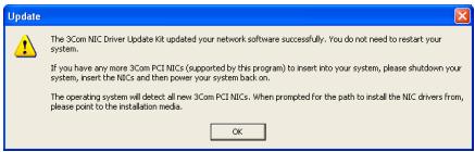
- Click [OK] to exit the installation.

Appendix D. Install VIA USB 2.0 Driver
NOTE: There is no need to install VIA USB 2.0 driver for the Windows XP operating system with Service Pack 1 already installed. Please run the Windows update for the latest Service Pack.
The installation procedures and screen shots in this section are based on Windows 2000 operating system. For those of other OS, please follow its on-screen instruction.
Insert the Driver & Utility CD into CD-ROM drive, it should execute the installation program automatically. If not, double-click the execution file at the main directory of this CD to enter the installation menu.
After entering the installation menu, move your curser to [Drivers] tab. Click [VIA USB 2.0 Driver]. The following screen appears.
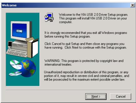
1. Click [Next].
![ABIT KV8-MAX3 - Click [Next]. - 1](/content/2025/01/174567/images/b9061ea94c598590ee75ff4a8257ea4d9d9f8a1e19dd95f604de7d2593ae5f5d.jpg)
2. Click [Yes].
![ABIT KV8-MAX3 - Click [Yes]. - 1](/content/2025/01/174567/images/c76892d3d1e363771f397cb34f15bd866931381b8444c803e4d40b7175c46f08.jpg)
3. Click [Next].
![ABIT KV8-MAX3 - Click [Next]. - 1](/content/2025/01/174567/images/d2b1b4cb46f3e658327e88bbf0bdcf47d87122d3cd5e3e5796e7280ff5cda735.jpg)
4. Click [Yes].
![ABIT KV8-MAX3 - Click [Yes]. - 1](/content/2025/01/174567/images/429951ee8f6a23294b49988a7a7476ffe40b06369d9726c778c1610877337c1a.jpg)
5. Click [Yes].
![ABIT KV8-MAX3 - Click [Yes]. - 1](/content/2025/01/174567/images/56db3aaac63be72a09cc86e293aea8ecfccdc8b16590bd81665fd907050164ba.jpg)
6. Click [Yes].
![ABIT KV8-MAX3 - Click [Yes]. - 1](/content/2025/01/174567/images/0980d85206b1ebed19245f179830246cb9ed43d8820a4bf63f6bc648e9082011.jpg)
7. Click [OK].
![ABIT KV8-MAX3 - Click [OK]. - 1](/content/2025/01/174567/images/d2e1509b68a00c620ca868e09b2dbb35e2099983ca8ae6ca3dc316917cd7c539.jpg)
8. Click [Print to File].
![ABIT KV8-MAX3 - Click [Print to File]. - 1](/content/2025/01/174567/images/b01cdd721773fb16214396bad92c715c3275887dd23710e81f36eea1668a47da.jpg)
9. Click [OK].
Appendix E. Install VIA Serial ATA RAID Driver
The installation procedures and screen shots in this section are based on Windows XP operating system. For those of other OS, please follow its on-screen instruction.
Insert the Driver & Utility CD into CD-ROM drive, it should execute the installation program automatically. If not, double-click the execution file at the main directory of this CD to enter the installation menu.
After entering the installation menu, move your cursor to [Drivers] tab. Click [VIA SATA RAID Driver]. The following screen appears.
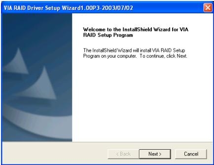
1. Click [Next].
![ABIT KV8-MAX3 - Click [Next]. - 1](/content/2025/01/174567/images/73e51d1f8036ec609675bc195ee7a1c5d054ab85a53d027a4a660b15133fe502.jpg)
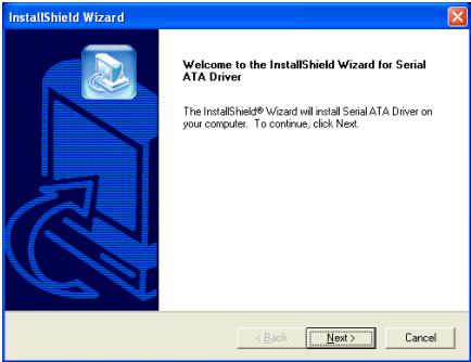
2. Click [Next].
![ABIT KV8-MAX3 - Click [Next]. - 1](/content/2025/01/174567/images/9b850daadd132260cd8688eaa8303e4a576fa3aed2eecee830e6895c6b942f87.jpg)
3. Click [Next].
![ABIT KV8-MAX3 - Click [Next]. - 1](/content/2025/01/174567/images/9854fa9e1f7442c4cbbbfa887411ac29bd206cf4ab09b9af4559eb25d02d49d7.jpg)
4. Click [Next].
![ABIT KV8-MAX3 - Click [Next]. - 1](/content/2025/01/174567/images/4d7bc678efaba38b674d036877277f0a63ad142a29b3911c336b1354e1aa9b37.jpg)
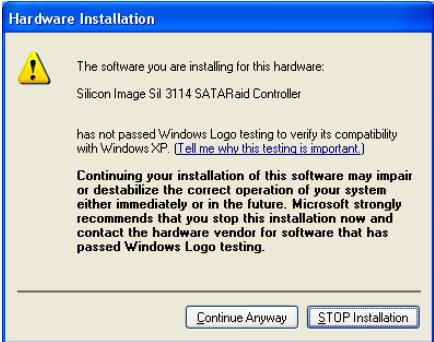
5. Click [Continue Anyway].
![ABIT KV8-MAX3 - Click [Continue Anyway]. - 1](/content/2025/01/174567/images/a213ccae15ce91a966372c7ccf80aeb8b88994db9090548bfab866eb1251d96f.jpg)
- Choose [Yes, I want to restart my computer now.], and click [Finish] to complete setup.
![ABIT KV8-MAX3 - Click [Continue Anyway]. - 2](/content/2025/01/174567/images/93a83c840af409aa9842d093099359744aceb4b8b1fc51e12b859b8803ce33bc.jpg)
- After the system restarted, a shortcut icon appears at the right corner of Windows task bar.
![ABIT KV8-MAX3 - Click [Continue Anyway]. - 3](/content/2025/01/174567/images/c5483305b1d167b6ee18c45bfc6d2698042b29da0698039dc4cad2bf4aa09272.jpg)
- This is the "VIA RAID Tool" configuration menu. For more information on how to operate, please refer to the "Help" menu.
Appendix F. Install Silicon Serial ATA RAID Driver
The installation procedures and screen shots in this section are based on Windows XP operating system. For those of other OS, please follow its on-screen instruction.
Insert the Driver & Utility CD into CD-ROM drive, it should execute the installation program automatically. If not, double-click the execution file at the main directory of this CD to enter the installation menu.
After entering the installation menu, move your cursor to [Drivers] tab. Click [Sil3114 SATA RAID Driver]. The following screen appears.
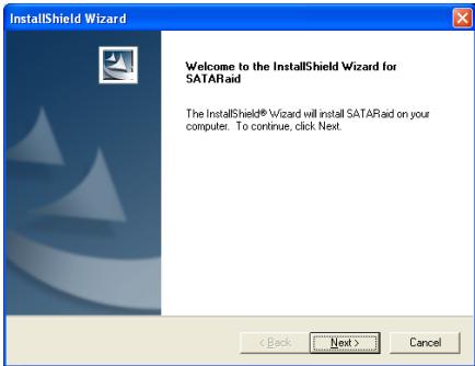
- Click [Next].
- Click [Continue Anyway].
- Click [Yes].
- Click [Next].
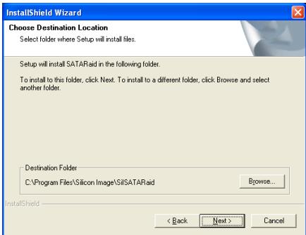
- Click [Next].
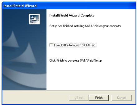
6. Click [Finish].
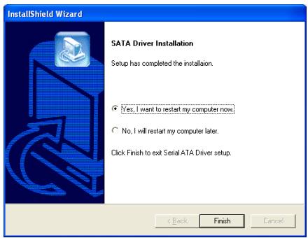
7. Choose [Yes, I want to restart my computer now.], and click [Finish] to complete setup.
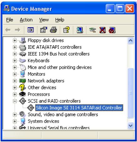
8. Check [Device Manager]. [Silicon Image SiI 3114 SATARaid Controller] is successfully installed.
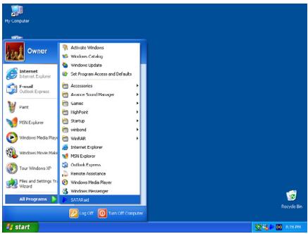
9. To run the [SATARaid] application, click [Start] [All Programs] [SATARaid].
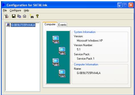
10. This is the SATALink configuration menu. For more information on how to operate, please refer to the "Help" menu.
BIOS Setup for Silicon Serial ATA RAID
This motherboard supports the RAID operation of "Striping (RAID 0)", "Mirroring (RAID 1)", or "Striping/Mirroring (RAID 0+1)" via Silicon Serial ATA controller. For the striping operation, the identical drives can read and write data in parallel to increase system performance. The Mirroring operation creates a complete backup of your files. Striping with Mirroring operation offers both read/write performance and fault tolerance.
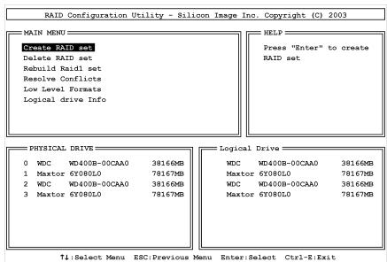
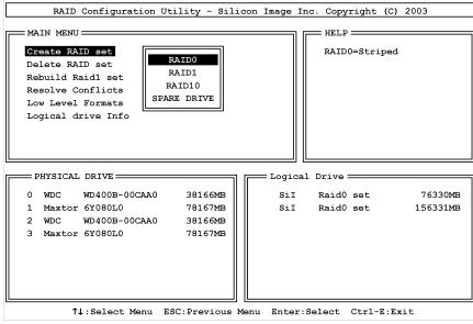
RAID Configuration Utility Menu
Main Menu
Reboot your system. Press <CTRL> + <S> or <F4> key while booting up the system to enter the BIOS setting menu. The main menu of BIOS Setting Utility appears as shown below:
To select the option in this menu, you may:
- Press < > (up, down arrow) to choose the option you want to confirm or to modify.
- Press
to confirm the selection. - Press
to return to previous menu. - Press
to exit the RAID configuration utility.
NOTE: If you want to create a RAID 0 (striping) array or RAID 0 + 1 array, all the data stored in the hard disks will first be erased! Please backup the hard disk data before starting to create these RAID arrays.
If you want to create a RAID 1 (mirroring) array, please make sure which hard disk is the source disk and which one is the destination disk. If you make a mistake, you may copy the blank data to the source disk, which will result in both hard disks becoming blank!
Option 1 Create RAID set
This item allows you to create a RAID array.
NOTE: It is highly recommended to attach hard disks with the same model in reaching the RAID performance.
RAID0: This item is recommended for high performance usage. Requires at least 2 disks.
RAID1: This item is recommended for data security usage. Requires at least 2 disks.
RAID10: This item is recommended for data security and high performance usage. Allows Mirroring with a Strip Array. Require 4 disks.
Option 2 Delete RAID set
This item allows you to remove a RAID Array on this onboard Serial ATA RAID controller.
NOTE: After you have made and confirmed this selection, all the data stored in the hard disk will be lost. (The entire partition configuration will be deleted too.)
Option 3 RebuildRaid1 set
This item allows you to rebuild only "Mirrored" RAID set.
You need to check which hard disk is the source disk and which one is the destination disk when you decide to rebuild mirrored RAID set.
Option 4 Resolve Conflicts
When a RAID set is created, the metadata written to the disk includes drive connection information (Primary Channel, Secondary Channel).
If, after a disk failure, the replacement disk was previously part of a RAID set (or used in another system), it may have conflicting metadata, specifically in reference to the drive connection information. If so, this will prohibit the RAID set from being either created or rebuilt.
In order for the RAID set to function properly, this old metadata must be first overwritten with the new metadata. To resolve this, select "Resolve Conflict". The correct metadata, including the correct drive connection information, will then be written to the replacement disk.
NOTE: For more information on RAID function, please refer to the RAID Management Software enclosed in the CD that came packed with this motherboard.
Option 5 Low Level Format
This item allows you to do the "Low Level Format" for each single HDD one at a time.
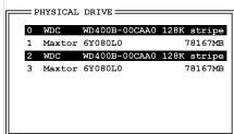
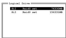
Option 6 Logical Drive Info
This item displays the drive information of the RAID type you had built.
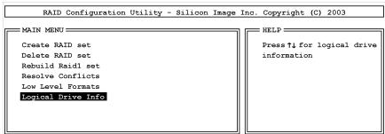
1:Select Menu ESC:Previous Menu Enter:Select Ctrl- Exit
Appendix G. Install ABIT μGuru Driver
ABIT μGuru is a fresh Microprocessor developed by ABIT engineers used only on ABIT motherboards. This processor combines the current ABIT engineered features into a user-friendly Windows-based interface, providing users a perfect environment to maximize PC performance and stability.
ABIT Guru family currently includes six categories:
- ABITEQ
- ABIT FanEQ
- ABITOC Guru
- ABIT FlashMenu
- ABIT AudioEQ
- ABIT BlackBox
To install the ABIT Guru driver, please insert the Driver & Utility CD into CD-ROM drive. It should execute the installation program automatically. If not, double-click the execution file at the main directory of this CD to enter the installation menu. The following screen appears.
Move your mouse to "ABIT Utility" tab. Click [ABIT Guru]. Follow the on-screen instruction to complete the driver installation.

Appendix H. POST Code Definition
AWARD POST Code Definition:
| POST (hex) | Description |
| CF | Test CMOS R/W functionality |
| C0 | Early chipset initialization: -Disable shadow RAM -Disable L2 cache (socket 7 or below) -Program basic chipset registers |
| C1 | Detect memory -Auto-detection of DRAM size, type and ECC -Auto-detection of L2 cache (socket 7 or below) |
| C3 | Expand compressed BIOS code to DRAM |
| C5 | Call chipset hook to copy BIOS back to E000 & F000 shadow RAM |
| 01 | Expand the Xgroup codes locating in physical address 1000:0 |
| 03 | Initial Superio_Early_Init switch |
| 05 | 1. Blank out screen 2. Clear CMOS error flag |
| 07 | 1. Clear 8042 interface 2. Initialize 8042 self-test |
| 08 | 1. Test special keyboard controller for Winbond 977 series Super I/O chips 2. Enable keyboard interface |
| 0A | 1. Disable PS/2 mouse interface (optional) 2. Auto detect ports for keyboard & mouse followed by a port & interface swap (optional) 3. Reset keyboard for Winbond 977 series Super I/O chips |
| 0E | Test F000h segment shadow to see whether it is R/W-able or not. If test fails, keep beeping the speaker |
| 10 | Auto detect flash type to load appropriate flash R/W codes into the run time area in F000 for ESCD & DMI support |
| 12 | Use walking 1's algorithm to check out interface in CMOS circuitry. Also set real-time clock power status, and then check for override |
| 14 | Program chipset default values into chipset. Chipset default values are MODBINable by OEM customers |
| 16 | Initial onboard clock generator if Early_Init_Onboard_Generator is defined. See also POST 26. |
| 18 | Detect CPU information including brand, SMI type (Cyrix or Intel) and CPU level (586 or 686) |
| 1B | Initial interrupts vector table. If no special specified, all H/W interrupts are directed to SPURIOUS_INT_HDLR & S/W interrupts to SPURIOUSsoft_HDLR. |
| 1D | Initial EARLY_PM_INIT switch |
| 1F | Load keyboard matrix (notebook platform) |
| 21 | HPM initialization (notebook platform) |
| 23 | 1. Check validity of RTC value: e.g. a value of 5Ah is an invalid value for RTC minute. 2. Load CMOS settings into BIOS stack. If CMOS checksum fails, use default value instead. |
| 24 | Prepare BIOS resource map for PCI & PnP use. If ESCD is valid, take into consideration of the ESCD's legacy information. |
| 25 | Early PCI Initialization: -Enumerate PCI bus number. -Assign memory & I/O resource -Search for a valid VGA device & VGA BIOS, and put it into C000:0 |
| 26 | 1. If Early_Init_Onboard_Generator is not defined Onboard clock generator initialization. Disable respective clock resource to empty PCI & DIMM slots. 2. Init onboard PWM 3. Init onboard H/W monitor devices |
| 27 | Initialize INT 09 buffer |
| 29 | 1. Program CPU internal MTRR (P6 & PII) for 0-640K memory address. 2. Initialize the APIC for Pentium class CPU. 3. Program early chipset according to CMOS setup. Example: onboard IDE controller. 4. Measure CPU speed. |
| 2B | Invoke Video BIOS |
| 2D | 1. Initialize double-byte language font (Optional) 2. Put information on screen display, including Award title, CPU type, CPU speed, full screen logo. |
| 33 | Reset keyboard if Early_Sett_KB is defined e.g. Winbond 977 series Super I/O chips. See also POST 63. |
| 35 | Test DMA Channel 0 |
| 37 | Test DMA Channel 1. |
| 39 | Test DMA page registers. |
| 3C | Test 8254 |
| 3E | Test 8259 interrupt mask bits for channel 1 |
| 40 | Test 8259 interrupt mask bits for channel 2 |
| 43 | Test 8259 functionality |
| 47 | Initialize EISA slot |
| 49 | 1. Calculate total memory by testing the last double word of each 64K page 2. Program writes allocation for AMD K5 CPU |
| 4E | 1. Program MTRR of M1 CPU 2. Initialize L2 cache for P6 class CPU & program CPU with proper cacheable range 3. Initialize the APIC for P6 class CPU 4. On MP platform, adjust the cacheable range to smaller one in case the cacheable ranges between each CPU are not identical |
| 50 | Initialize USB |
| 52 | Test all memory (clear all extended memory to 0) |
| 53 | Clear password according to H/W jumper (Optional) |
| 55 | Display number of processors (multi-processor platform) |
| 57 | Display PnP logo Early ISA PnP initialization -Assign CSN to every ISA PnP device |
| 59 | Initialize the combined Trend Anti-Virus code |
| 5B | (Optional Feature) Show message for entering AWDFLASH.EXE from FDD (optional) |
| 5D | 1. Initialize Init_Onboard_Super_IO 2. Initialize Init_OnbaordAUDIO |
| 60 | Okay to enter Setup utility; i.e. not until this POST stage can users enter the CMOS setup utility |
| 63 | Reset keyboard if Early_Sett KB is not defined |
| 65 | Initialize PS/2 Mouse |
| 67 | Prepare memory size information for function call: INT 15h ax=E820h |
| 69 | Turn on L2 cache |
| 6B | Program chipset registers according to items described in Setup & Auto-configuration table |
| 6D | 1. Assign resources to all ISA PnP devices 2. Auto assign ports to onboard COM ports if the corresponding item in Setup is set to “AUTO” |
| 6F | 1. Initialize floppy controller 2. Set up floppy related fields in 40:hardware |
| 75 | Detect & install all IDE devices: HDD, LS120, ZIP, CDROM ... |
| 76 | (Optional Feature) Enter AWDFLASH.EXE if: -AWDFLASH is found in floppy drive -ALT+F2 is pressed |
| 77 | Detect serial ports & parallel ports. |
| 7A | Detect & install co-processor |
| 7C | Init HDD write protect |
| 7F | Switch back to text mode if full screen logo is supported -If errors occur, report errors & wait for keys -If no errors occur or F1 key is pressed to continue: Clear EPA or customization logo |
| E8POST.ASM starts | |
| 82 | 1. Call chipset power management hook 2. Recover the text font used by EPA logo (not for full screen logo) 3. If password is set, ask for password |
| 83 | Save all data in stack back to CMOS |
| 84 | Initialize ISA PnP boot devices |
| 85 | 1. USB final Initialization 2. Switch screen back to text mode |
| 87 | NET PC: Build SYSID Structure |
| 89 | 1. Assign IRQs to PCI devices 2. Set up ACPI table at top of the memory. |
| 8B | 1. Invoke all ISA adapter ROMs 2. Invoke all PCI ROMs (except VGA) |
| 8D | 1. Enable/Disable Parity Check according to CMOS setup 2. APM Initialization |
| 8F | Clear noise of IRQs |
| 93 | Read HDD boot sector information for Trend Anti-Virus code |
| 94 | 1. Enable L2 cache 2. Program Daylight Saving 3. Program boot up speed 4. Chipset final initialization. 5. Power management final initialization 6. Clear screen & display summary table 7. Program K6 write allocation 8. Program P6 class write combining |
| 95 | Update keyboard LED & typematic rate |
| 96 | 1. Build MP table 2. Build & update ESCD 3. Set CMOS century to 20h or 19h 4. Load CMOS time into DOS timer tick 5. Build MSIRQ routing table |
| FF | Boot attempt (INT 19h) |
AC2003 POST Code Definition:
| POST (hex) | Description |
| Power On Sequence | |
| 8.1. | Start power on sequence |
| 8.2. | Enable ATX power supply |
| 8.3. | ATX power supply ready |
| 8.4. | DDR voltage ready |
| 8.5. | Setup PWM for CPU core voltage |
| 8.6. | Assert PWM for CPU core voltage |
| 8.7. | Check CPU core voltage |
| 8.8. | CPU core voltage ready |
| 8.9. | Initial clock generator IC |
| 8.A. | North Bridge chipset voltage ready |
| 8.B. | AGP voltage ready |
| 8.C. | 3VDUAL voltage ready |
| 8.D. | VDDA 2.5V voltage ready |
| 8.D. | GMCHVTT voltage ready |
| 8.E. | Check CPU fan speed |
| 8.F. | Assert all power ready |
| 9.0. | Complete uGuru initial processAWARD BIOS take over booting job |
| Power Off Sequence | |
| 9.1. | Start power off sequence |
| 9.2. | De-Assert all power |
| 9.3. | Se-Assert power on |
| 9.4. | De-Assert LDT Bus power |
| 9.5. | De-Assert PWM for CPU core voltage |
| 9.6. | De-Assert CPU core voltage |
| 9.7. | Check CPU core voltage |
| 9.8. | De-Assert ATX power supply |
| 9.9. | Complete power off sequence |
| Others | |
| F.0. | Button reset |
| F.1. | SoftMenu reset |
| F.2. | Power on sequence timeout |
| F.3. | Power off sequence timeout |
NOTE: The decimal point lights up when executing the AC2003 POST action.

Appendix I. Troubleshooting (Need Assistance?)
Q & A:
Q: Do I need to clear the CMOS before I use a new motherboard to assemble my new computer system?
A: Yes, we highly recommend that you clear the CMOS before installing a new motherboard. Please move the CMOS jumper from its default 1-2 position to 2-3 for a few seconds, and then back. When you boot up your system for the first time, follow the instructions in the user's manual to load the optimized defaults.
Q: If my systems hang when I update the BIOS or set the wrong CPU parameters, what should I do?
A: Whenever you update the BIOS or if the system hangs due to wrong CPU parameters setting, always clear CMOS jumper before booting up again.
Q: Why the system failed to boot up and nothing was displayed on the screen after I did some over-clocking or non-standard settings inside the BIOS? Is the motherboard dead? Do I need to return it to where I bought from or go through an RMA process?
A: It should not cause hardware or permanent damage to motherboard when BIOS settings were changed from default to over-clocking or non-standard status.
We suggest the following three troubleshooting methods to discharge CMOS data, recover the hardware default status, and then make the motherboard working again. No need to bother returning the motherboard to where you bought from or go through an RMA process.
Step 1. Switch off the power supply unit and then switch it on again after one minute. If there is no power switch on the power supply unit, disconnect its power cord for one minute and then connect it back.
Press and hold the key to enter the BIOS setup page to do the correct settings.
If the situation remains the same, repeat the procedures in Step 1 for three times, or try Step 2.
Step 2. Switch off the power supply unit or disconnect the power cord. Open the chassis cover. Locate the CCMOS jumper near the button battery. Change the jumper position from default 1-2 to 2-3 for one minute to discharge the CMOS data, and then put it back to default 1-2 position.
Close the chassis and switch on the power supply unit or plug in the power cord. Press the power-on button to boot up system. If it works, hit key to enter the BIOS setup page to do the correct settings.
If the situation remains the same, try Step 3.
Step 3. The same procedure as Step 2, but in the meantime of discharging the CMOS data, pull out ATX power connectors from motherboard and remove the button battery during CMOS discharging.
Q: How can I get a quick response to my request for technical support?
A: Be sure to follow the guidelines as stated in the "Technical Support Form" section of this manual.
If you have a problem during operation, in order to help our technical support personnel quickly determine the problem with your motherboard and give you the answers you need, before filling in the technical support form, eliminate any peripheral that is not related to the problem, and indicate it on the form. Fax this form to your dealer or to the company where you bought the hardware in order to benefit from our technical support. (You can refer to the examples given below)
Example 1:
With a system including: motherboard (with CPU, DRAM, COAST...) HDD, CD-ROM, FDD, VGA CARD, MPEG CARD, SCSI CARD, SOUND CARD, etc. After the system is assembled, if you cannot boot up, check the key components of the system using the procedure described below. First remove all interface cards except the VGA card and try to reboot.
If you still cannot boot up: Try installing another brand/model VGA card and see if the system will start. If it still does not start, note the VGA card model, motherboard model, Bios identification number, CPU on the technical support form (refer to main instructions), and describe the problem in the problem description space provided.
If you can boot up: Insert the interface cards you have removed back into the system, one by one and try to start the system each time you insert a card, until the system will not start. Keep the VGA card and the interface card that caused the problem inserted on the motherboard, remove any other cards or peripheral, and start again. If you still cannot start, note the information related to both cards in the add-on Card space provided, and don't forget to indicate the motherboard model, version, BIOS identification number, CPU (refer to main instructions), and give a description of the problem.
Example 2:
With a system including the motherboard (with CPU, DRAM, COAST...) HDD, CD-ROM, FDD, VGA CARD, LAN CARD, MPEG CARD, SCSI CARD, SOUND CARD, after assembly and after having installed the Sound Card Driver, when you restart the system, when it runs the Sound Card Driver, it resets automatically. This problem may be due to the Sound Card Driver. During the Starting DOS... procedure, press SHIFT (BY-PASS) key, to skip CONFIG.SYS and AUTOEXEC.BAT; edit CONFIG.SYS with a text editor, and in function the line that loads the Sound Card Driver, add a remark REM, in order to disable the Sound Card Driver. See the example below.
CONFIG.SYS:
DEVICE=C:\DOS\HIMEM.SYS
DEVICE=C:\DOS\EMM386.EXE HIGHSCAN
DOS=HIGH, UMB
FILES=40
BUFFERS=36
REM DEVICEHIGH=C:\PLUGPLAY\DWCFGMG.SYS
LASTDRIVE =
Restart the system. If the system starts and does not reset, you can be sure that the problem is due to the Sound Card Driver. Write down the Sound Card model, motherboard model, BIOS identification number on the technical support file (refer to main instructions), and describe the problem in the space provided.
We will show you how to fill the "Technical Support Form".
Main instructions:
To fill in this "Technical Support Form", refer to the step-by-step instructions given below:
- MODEL: Note the model number given in your user's manual.
Example: KV8-MAX3
2. Motherboard model number (REV): Note the motherboard model number labeled on the motherboard as "REV:.".
Example: REV: 1.01
3. BIOS ID and Part Number: See the on screen message.
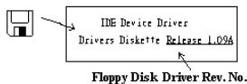
4. DRIVER REV: Note the driver version number indicated on the DEVICE DRIVER disk (if any) as "Release .". For example:
5. OS/APPLICATION: Indicate the operating system and applications you are running on the system.
Example: MS-DOS 6.22
Windows 98 SE, Windows 2000, etc....
6^* .CPU:Indicate the brand and the speed (MHz) of your CPU.
Example:(A) In the "Brand" space, write "Intel"; in the "Specifications" space, write "Pentium® 4 1.9GHz".
- HDD: Indicate the brand and specifications of your HDD(s); specify if the HDD is using IDE1 or IDE2. If you know the disk capacity, indicate it and check ("✓") "☐"; in case you give no indication, we will consider that your HDD is "IDE1" Master.
Example: In the "HDD" space, check the box; in the Brand space, write "Seagate"; in the Specifications space, write "ST31621A (1.6GB)".
- CD-ROM Drive: Indicate the brand and specifications of your CD-ROM drive. Specify if it uses IDE1 or IDE2, and check ("✓") "☐"; in case you give no indication, we will consider that your CD-ROM is "IDE2" Master.
Example: In the "CD-ROM drive" space, check the box, in the Brand space, write "Mitsumi", in the Specifications space, write "FX-400D".
- System Memory (DDR SDRAM): Indicate the brand and specifications (DDR DIMM) of your system memory. Such as Density, Description, Module Components, Module Part Number, CAS Latency, and Speed (MHz).
For example: In the Brand space, write "Micron"; in the Specifications space, write: Density: 128MB, Description: SS 16 Megx72 2.5V ECC Gold, Module Components: (9) 16 Megx 8, Module Part Number: MT9VDDT1672AG, CAS Latency: 2, Speed (MHz): 200 MHz.
Please give us the detailed information of your DDR SDRAM module; it will help us to simulate the problems you met.
- ADD-ON CARD: Indicate which add-on cards you are absolutely sure are related to the problem.
If you cannot identify the problem's origin, indicate all the add-on cards inserted into your system.
NOTE: Items between the “*” are absolutely necessary.

Technical Support Form

Company Name:

Phone Number:

Contact Person:

Fax Number:

E-mail Address:
| Model | * | BIOS ID # | * |
| Motherboard Model No. | DRIVER REV | ||
| OS/Application | * | ||
| Hardware Name | Brand | Specifications | |
| CPU | * | ||
| HDD IDE1IDE2 | |||
| CD-ROM-Drive IDE1IDE2 | |||
| System Memory | |||
| ADD-ON CARD | |||
Problem Description:
Appendix J. How to Get Technical Support
(From our website) http://www.abit.com.tw
(In North America) http://www.abet-usa.com
(In Europe) http://www.abit.nl
Thank you for choosing ABIT products. ABIT sells all our products through distributors, resellers and system integrators; we have no direct sales to end-users. Before sending email for tech support please check with your resellers or integrators if you need any services, they are the ones who sold you your system and they should know best as to what can be done, how they serve you is a good reference for future purchases.
We appreciate every customer and would like to provide the best service to you. Providing fast service to our customers is our top priority. However we receive many phone calls and a huge amount of email from all over the world. At the present time it is impossible for us to respond to every single inquiry. Therefore it is quite possible that if you send an email to us that you may not receive a response.
We have done many compatibility tests and reliability tests to make sure our products have the best quality and compatibility. In case you need service or technical support, please understand the constraint we have and always check with the reseller who sold the product to you first.
To expedite service, we recommend that you follow the procedures outlined below before contacting us. With your help, we can meet our commitment to provide the best service to the greatest number of ABIT customers:
- Check the Manual. It sounds simple but we have taken a lot of care in making a well-written and thorough manual. It is full of information that doesn't only pertain to motherboards. The CD-ROM included with your board will have the manual as well as drivers. If you don't have either one, go to our Program Download Area of the Website or FTP server.
- Download latest BIOS, software or drivers. Please go to our Program Download area on our Website to check to see if you have the latest BIOS. They are developed over periods of time to fixes bugs or incompatibilities. Also please make sure you have the latest drivers from your peripheral cards makers!
-
Check the ABIT Technical Terms Guide and FAQ on our Website. We are trying to expand and make the FAQs more helpful and information rich. Let us know if you have any suggestions. For hot topics, check out our HOT FAQ!
-
Internet Newsgroups. They are a great source of information and many people there can offer help. ABIT's Internet News group, alt.comp.periphs.mainboard.abit, is an ideal forum for the public to exchange information and discuss experiences they have had with ABIT products. Many times you will see that your question has already been asked before. This is a public Internet news group and it is reserved for free discussions. Here is a list of some of the more popular ones:
alt.comp.periphs.mainboard.abit
comp.sys.ibm.pc.hardware.chips
alt.comp.hardware.overlocking
alt.comp.hardware.homebuilt
alt.comp.hardware.pc-homebuilt
- Ask your reseller. Your ABIT authorized distributor should be able to provide the fastest solution to your technical problem. We sell our products through distributors who sell to resellers and stores. Your reseller should be very familiar with your system configuration and should be able to solve your problem much more efficiently than we could. After all, your reseller regards you as an important customer who may purchase more products and who can urge your friends to buy from him or her as well. They integrated and sold the system to you. They should know best what your system configuration is and your problem. They should have reasonable return or refund policies. How they serve you is also a good reference for your next purchase.
- Contacting ABIT. If you feel that you need to contact ABIT directly you can send email to the ABIT technical support department. First, please contact the support team for the branch office closest to you. They will be more familiar with local conditions and problems and will have better insight as to which resellers offer what products and services. Due to the huge number of emails coming in every day and other reasons, such as the time required for problem reproduction, we will not be able to reply to every email. Please understand that we are selling through distribution channels and don't have the resources to serve every end-user. However, we will try to do our best to help every customer. Please also remember that for many of our technical support team English is a second language, you will have a better chance of getting a helpful answer if your question can be understood in the first place. Be sure to use very, simple, concise language that clearly states the problem, avoid rambling or flowery language and always list your system components. Here is the contact information for our branch offices:
North America and South America:
ABIT Computer (U.S.A.) Corporation
45531 Northport Loop West,
Fremont, California 94538, U.S.A.
Tel: 1-510-623-0500
Fax: 1-510-623-1092
sales@abit-usa.com
technical@abit-usa.com
http://www.ubit-usa.com
U.K. and Ireland:
ABIT Computer (U.K.) Corporation Ltd.
Unit 3, 24-26 Boulton Road,
Stevenage, Herts SG1 4QX, U.K.
Tel: 44-1438-228888
Fax: 44-1438-226333
sales@abitcomputer.co.uk
technical@abitcomputer.co.uk
Germany, Benelux (Belgium,
Netherlands, Luxembourg), Denmark,
Norway, Sweden, Finland, and
Switzerland:
AMOR Computer B.V. (ABIT's European Office)
Austria, Czech, Romania, Bulgaria,
Yugoslavia, Slovakia, Slovenia, Croatia,
Bosnia, Serbia, and Macedonia:
Asguard Computer Ges.m.b.H
Schmalbachstrasse 5,
A-2201 Gerasdorf/Wien, Austria
Tel: 43-1-7346709
Fax: 43-1-7346713
asguard@asguard.at
Japan:
ABIT Computer (Japan) Co. Ltd.
Fax: 81-3-5396-5110
http://www.abit4u.jp
Shanghai:
ABIT Computer (Shanghai) Co. Ltd.
Tel: 86-21-6235-1829
Fax: 86-21-6235-1832
http://www.abit.com.cn
Russia:
ABIT Computer (Russia) Co. Ltd.
Fax: 7-095-937-2837
techrussia@abit.com.tw
http://www.abit.ru
France, Italy, Spain, Portugal, and
Greece:
ABIT Computer France SARL
Tel: 33-1-5858-0043
Fax: 33-1-5858-0047
http://www.abit.fr
All other territories not covered above
please contact Taiwan Head Office:
When contacting our headquarters please Note we are located in Taiwan and we are 8+ GMT time. In addition, we have holidays that may be different from those in your country.
ABIT Computer Corporation
No.323, Yang Guang St., Neihu, Taipei, 114, Taiwan
Tel: 886-2-8751-8888
Fax: 886-2-8751-3382
sales@abit.com.tw
market@abit.com.tw
technical@abit.com.tw
http://www.abit.com.tw
- RMA Service. If your system has been working but it just stopped, but you have not installed any new software or hardware recently, it is likely that you have a defective component. Please contact the reseller from whom you bought the product. You should be able to get RMA service there.
- Reporting Compatibility Problems to ABIT. Because of tremendous number of email messages we receive every day, we are forced to give greater weight to certain types of messages than to others. For this reason, any compatibility problem that is reported to us, giving detailed system configuration information and error symptoms will receive the highest priority. For the other questions, we regret that we may not be able to reply directly. But your questions may be posted to the Internet news group in order that a larger number of users can have the benefit of the information. Please check the news group from time to time.
- The information listed below are some chipset vendors' WEB site addresses for your reference:
HighPoint Technology Inc.'s WEB site: http://www.highpoint-tech.com/
Intel's WEB site: http://www.intel.com/
Silicon Image's WEB site: http://www.siimage.com/