
AB9 QUADGT - Motherboard ABIT - Free user manual and instructions
Find the device manual for free AB9 QUADGT ABIT in PDF.
| Product Type | Motherboard |
| Brand | ABIT |
| Model | AB9 QUADGT |
| Form Factor | ATX (305 x 244 mm) |
| CPU Socket | LGA775 (supports Intel Core 2 Quad) |
| Chipset | Intel P965 |
| Supported Memory | DDR2 (up to 4 slots) |
| Expansion Slots | 1x PCI Express x16, 2x PCI Express x1, 3x PCI |
| Storage Connectors | 6x SATA 3Gb/s, 1x IDE Ultra ATA |
| Back Panel Connectors | PS/2 mouse, PS/2 keyboard, LPT, COM, S/PDIF optical in/out, Audio 7.1 (3 jacks), IEEE1394a, Gigabit LAN, 4x USB 2.0 |
| Required Power Supply | ATX 24-pin + 4-pin CPU |
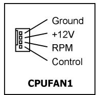
| CPU Cooler | CPUFAN1 connector (4-pin) |
| CMOS Clear | Dedicated jumper on board |
| Weight | Approximately 0.8 kg |
| Main Features | Supports Intel Core 2 Quad, DDR2 memory, 7.1-channel audio, Gigabit LAN, IEEE1394 Firewire, USB 2.0 |
| Maintenance and Cleaning | Use a soft, dry cloth. Do not use solvents. |
| Safety | Disconnect power before handling. Wear an antistatic wrist strap. |
| Spare Parts and Repairability | Components are not user-repairable. Contact after-sales service. |
| General Information | Instruction manual available for free download. |
Frequently Asked Questions - AB9 QUADGT ABIT
User questions about AB9 QUADGT ABIT
0 question about this device. Answer the ones you know or ask your own.
Ask a new question about this device
Download the instructions for your Motherboard in PDF format for free! Find your manual AB9 QUADGT - ABIT and take your electronic device back in hand. On this page are published all the documents necessary for the use of your device. AB9 QUADGT by ABIT.
USER MANUAL AB9 QUADGT ABIT
This user's manual contains all the information you may need for setting up this motherboard. To read the user's manual of PDF format (readable by Adobe Reader), place the "Driver & Utility CD" into the CD-ROM drive in your system. The auto-run screen will appear, click the "Manual" tab to enter its submenu. If not, browse the root directory of the CD-ROM via the File Manager, and double click the "AUTORUN" file.
LGA775ATX
Intel P965/ICH8R
FSB 1066/800/533 MHz
Dual DDR2 800
Dual PCI-E X16 Graphics Slots
Gigabit LAN
8x SATA 3Gb/s with RAID
IEEE1394
7.1 Channel HD Audio
uGuru™ Technology
Silent OTES™ Technology
External CMOS Clearing Switch
Quick Power & Reset Button
Vista HW Ready
AB9 QuadGT
User's Manual
English + Multilingual QIG
2^nd Edition, January 2007
Copyright and Warranty Notice
The information in this document is subject to change without notice and does not represent a commitment on part of the vendor, who assumes no liability or responsibility for any errors that may appear in this manual.
No warranty or representation, either expressed or implied, is made with respect to the quality, accuracy or fitness for any particular part of this document. In no event shall the manufacturer be liable for direct, indirect, special, incidental or consequential damages arising from any defect or error in this manual or product.
Product names appearing in this manual are for identification purpose only and trademarks and product names or brand names appearing in this document are the property of their respective owners.
This document contains materials protected under International Copyright Laws. All rights reserved. No part of this manual may be reproduced, transmitted or transcribed without the expressed written permission of the manufacturer and authors of this manual.
If you do not properly set the motherboard settings, causing the motherboard to malfunction or fail, we cannot guarantee any responsibility.
1. Hardware Setup 1-1
1.1 Specifications 1-1
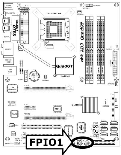
1.2 Motherboard Layout 1-2
1.3 Choosing a Computer Chassis 1-3
1.4 Installing Motherboard 1-3
1.5 Checking Jumper Settings 1-4
1.5.1 CMOS Memory Clearing Header and Backup Battery 1-4
1.5.2 Wake-up Header 1-6
1.6 Connecting Chassis Components 1-7
1.6.1ATXPower Connectors 1-7
1.6.2 Front Panel Switches & Indicators Headers 1-8
1.6.3 FAN Power Connectors 1-9
1.6.4 abit Silent OTES™ Technology 1-9
1.7 Installing Hardware 1-10
1.7.1 CPU Socket 775 1-10
1.7.2 DDR2 Memory Slots 1-12
1.7.3 PCI Express X16 Add-on Slots (Install Graphics Card) 1-13
1.8 Connecting Peripheral Devices 1-15
1.8.1 Floppy and IDE Disk Drive Connectors 1-15
1.8.2 Serial ATA Connectors 1-16
1.8.3 Additional USB 2.0 Port Headers.. 1-17
1.8.4 Additional IEEE1394 Port Header 1-17
1.8.5 Internal Audio Connectors 1-18
1.8.6 Front Panel Audio Connection Header 1-18
1.8.7 S/PDIF Output Connection Header 1-20
1.8.8 PCI and PCI Express X1 Slot.. 1-20
1.8.9 Guru Panel Connection Header 1-21
1.9 Onboard Indicators and Buttons 1-22
1.9.1 POST Code Displayer 1-22
1.9.2 Power Source Indicators 1-23
1.9.3 Onboard Buttons 1-23
1.10 Connecting Rear Panel I/O Devices 1-24
2. BIOS Setup 2-1
2.1 μGuru™ Utility 2-2
2.1.1 OC Guru 2-2
2.1.2 ABIT EQ. 2-4
2.2 Standard CMOS Features 2-10
2.3 Advanced BIOS Features 2-13
2.4 Advanced Chipset Features 2-16
2.5 Integrated Peripherals 2-17
2.6 Power Management Setup 2-20
2.7 PnP/PCI Configurations 2-23
2.8 Load Fail-Safe Defaults.. 2-24
2.9 Load Optimized Defaults 2-24
2.10 Set Password 2-24
2.11 Save & Exit Setup 2-24
2.12 Exit Without Saving 2-24
3. Driver & Utility 3-1
3.1 CD-ROM AUTORUN 3-1
3.2 Intel Chipset Software Installation Utility 3-2
3.3 Intel Matrix Storage Manager 3-2
3.4 Audio Driver 3-3
3.5 LAN Driver 3-4
3.6 JMicron SATA Driver 3-4
3.7 USB 2.0 Driver 3-4
3.8 ABIT μGuru Utility 3-5
3.9 Build Intel SATA RAID Driver Disk Under Windows Environment .... 3-6
3.10 Build JMicron SATA RAID Driver Disk Under Windows Environment 3-7
3.11 Build A Driver Disk Under DOS Environment 3-8
4. Multilingual Quick Installation Guide 4-1
4.1 Français//Guide d'Installation Rapide 4-1
4.2 Deutsch//Kurze Installationsanleitung 4-2
4.3 Italiano//Guida all'installazione rapida 4-3
4.4 Espanol//Guía
4-4
4.5 Portugues//Guia de instalação rápida 4-5
4.6 Pycckn//KpaTkoe pykoBOdCTBO no yctaHOBKe 4-6
4.7 Eesti//Kiirpaigaldusjuhend 4-7
4.8 Latviski//Atras instalësanas instrukcija 4-8
4.9 Lietuviu//Trumpas instalavimo vadovas 4-9
4.10 Polski//Instrukcja szybkiej instalacji 4-10
4.11 Magyar//Gyorstelepiési utmutató 4-11
4.12 Türkç//Hizl Kurulum Kilavuzu 4-12
4.13 UJg dUg/Us//UuU UuRrUuRsrE 4-13
4.14 /Jrws//JouolssuWwSsE 4-14
4.15 日本語//ケイククインスートルガイド 4-15
4.16 韩国兒//哪在刻儿德 4-16
4.17 Bahasa Malaysia//Panduan Pemasangan Ringkas 4-17
4.18 1n//nnnnnnnnnnnnnnnnnnnnnnnnnnnnnnnnnnnnnnnnnnnnnnnnnnnnnnnnnnnnnnnnnnnnnnnnnnnnnnnnnnnnnnnnnnnnnnnnnnnnnnnnnn
4.19 繁體中文 4-19
5.2 Troubleshooting (How to Get Technical Support?) 5-5
5.2.1 Q & A 5-5
5.2.2 Technical Support Form.. 5-8
5.2.3 Universal ABIT Contact Information 5-9

1. Hardware Setup
1.1 Specifications
CPU
- LGA775 socket for Intel Core 2 Quad / Core 2 Duo / Core 2 Extreme / Pentium Dual Core / Pentium Extreme / Pentium D / Pentium 4
- FSB 1066/800/533 MHz
Chipset
Intel P965 / ICH8R
Memory
- 4x 240-pin DIMM slots support maximum memory capacity up to 8GB
Supports Dual Channel DDR2 800/667/533 Un-buffered Non-ECC memory
LAN
- Onboard 10/100/1000M PCI Gigabit controller
Audio
- Onboard 7.1 CH HD Audio CODEC
Supports auto jack sensing and optical S/PDIF In/Out
HDMI Header ready (S/PDIF Header)
Serial ATA
- 6x SATA 3Gb/s offered by Intel ICH8R support Intel Matrix Storage Tech (AHCI & RAID 0, 1, 5, and 10)
- 2x SATA 3Gb/s offered by JMicron JMB363 support RAID 0, 1, and JBOD
IEEE1394
Supports 2 Ports IEEE1394 at 400Mb/s transfer rate
Expansion Slots
- 1x PCI-E X16 slot (x16 bandwidth)
- 1x PCI-E X16 slot (x4 bandwidth)
-
1x PCI-E X1 slot
-
2x PCI slots
Internal I/O Connectors
- 1x Floppy port
1x ATA 100 IDE connector - 6x SATA 3Gb/s connectors
- 3x USB 2.0 headers
1x IEEE1394 header
1x FP-Audio header
1x CD-In connector - 1x S/PDIF Out header
1x GURU header
Rear Panel I/O
1x PS/2 Keyboard connector
1x PS/2 Mouse connector
1x External CMOS Clearing Switch
1x S/PDIF In connector
1x S/PDIF Out connector
2x eSATA connectors
1x 7.1CH Audio connector
4x USB 2.0 connectors
1x IEEE1394 connector
1x RJ-45 Gigabit LAN connector
abit Engineered
- abit uGuru ™ Technology
- abit Silent OTES™ Technology
External CMOS Clearing Switch - Quick Power & Reset Button
RoHS
100% Lead-free process and RoHS compliant
Miscellaneous
- ATX form factor (305mm x 245mm)
- Vista HW Ready
※ Specifications and information contained herein are subject to change without notice.
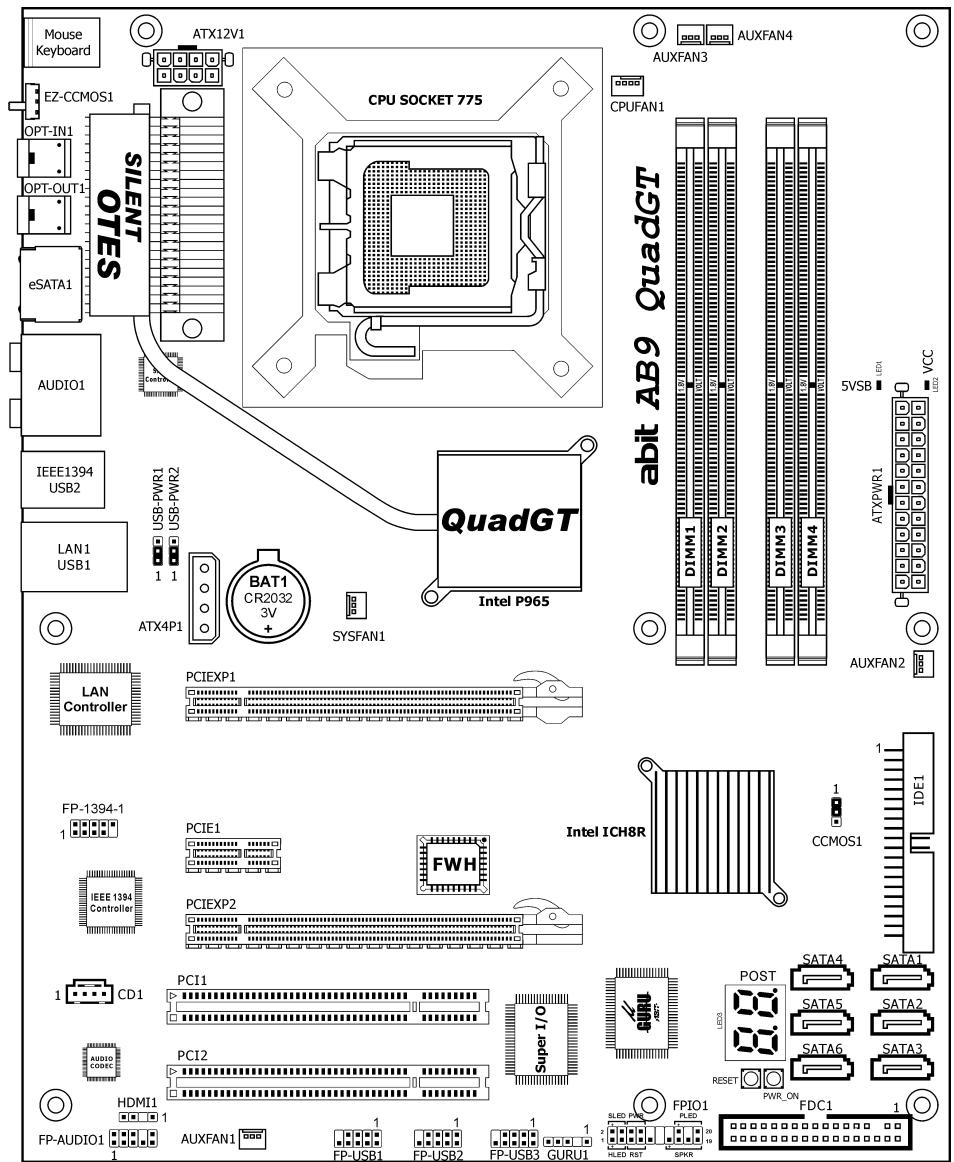
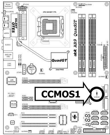
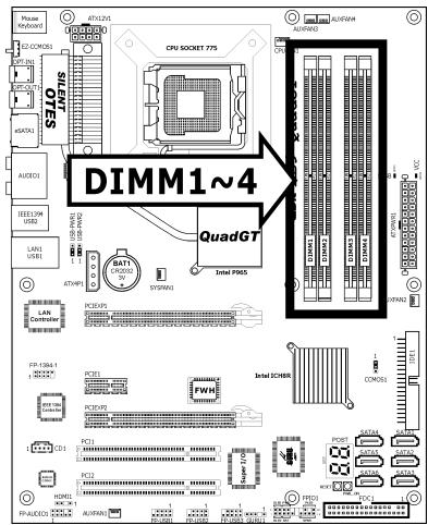
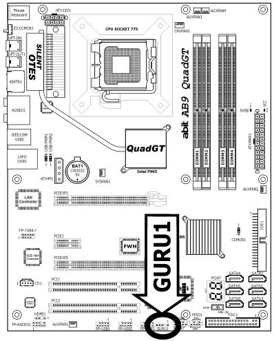
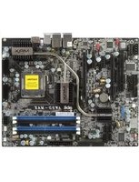
1.2 Motherboard Layout
1.3 Choosing a Computer Chassis
- Choose a chassis big enough to install this motherboard.
- As some features for this motherboard are implemented by cabling connectors on the motherboard to indicators and switches or buttons on the chassis, make sure your chassis supports all the features required.
- If there is a possibility of adopting some more hard drives, make sure your chassis has sufficient power and space for them.
- Most chassis have alternatives for I/O shield located at the rear panel. Make sure the I/O shield of the chassis matches the I/O port configuration of this motherboard. You can find an I/O shield specifically designed for this motherboard in its package.
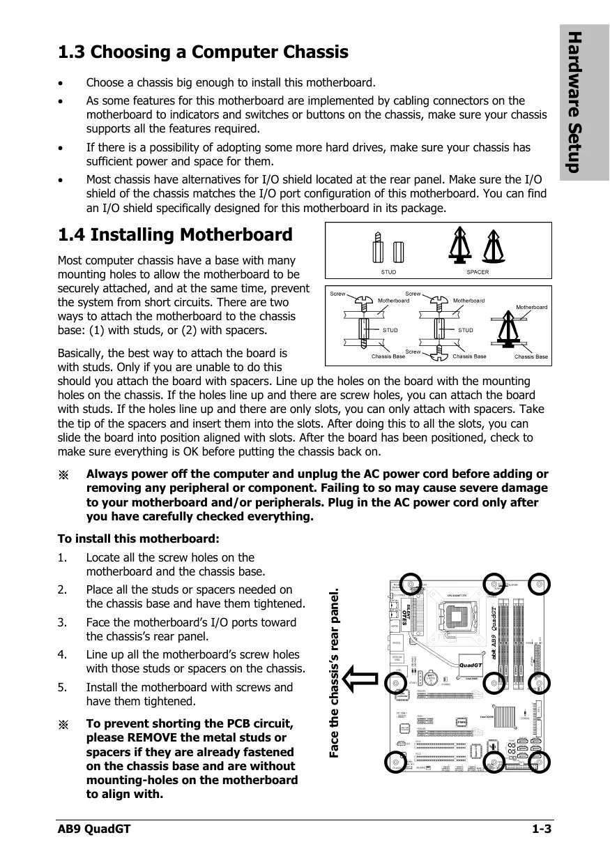
1.4 Installing Motherboard
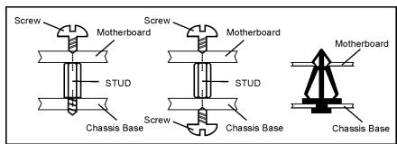
Most computer chassis have a base with many mounting holes to allow the motherboard to be securely attached, and at the same time, prevent the system from short circuits. There are two ways to attach the motherboard to the chassis base: (1) with studs, or (2) with spacers.
Basically, the best way to attach the board is with studs. Only if you are unable to do this
should you attach the board with spacers. Line up the holes on the board with the mounting holes on the chassis. If the holes line up and there are screw holes, you can attach the board with studs. If the holes line up and there are only slots, you can only attach with spacers. Take the tip of the spacers and insert them into the slots. After doing this to all the slots, you can slide the board into position aligned with slots. After the board has been positioned, check to make sure everything is OK before putting the chassis back on.

Always power off the computer and unplug the AC power cord before adding or removing any peripheral or component. Failing to so may cause severe damage to your motherboard and/or peripherals. Plug in the AC power cord only after you have carefully checked everything.
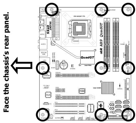
To install this motherboard:
- Locate all the screw holes on the motherboard and the chassis base.
- Place all the studs or spacers needed on the chassis base and have them tightened.
- Face the motherboard's I/O ports toward the chassis's rear panel.
- Line up all the motherboard's screw holes with those studs or spacers on the chassis.
- Install the motherboard with screws and have them tightened.
※ To prevent shorting the PCB circuit, please REMOVE the metal studs or spacers if they are already fastened on the chassis base and are without mounting-holes on the motherboard to align with.
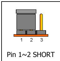
1.5 Checking Jumper Settings
- For a 2-pin jumper, plug the jumper cap on both pins will make it CLOSE (SHORT). Remove the jumper cap, or plug it on either pin (reserved for future use) will leave it at OPEN position.
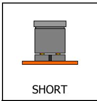
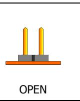
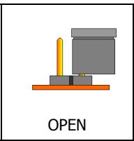
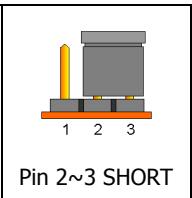
- For 3-pin jumper, pin 1 2 or pin 2 3 can be shorted by plugging the jumper cap in.
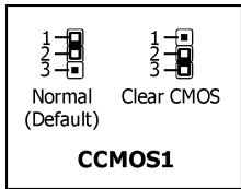
1.5.1 CMOS Memory Clearing Header and Backup Battery
The time to clear the CMOS memory occurs when (a) the CMOS data becomes corrupted, (b) you forgot the supervisor or user password preset in the BIOS menu, (c) you are unable to boot-up the system because the CPU ratio/clock was incorrectly set in the BIOS menu, or (d) whenever there is modification on the CPU or memory modules.
This header uses a jumper cap to clear the CMOS memory and have it reconfigured to the default values stored in BIOS.
- Pins 1 and 2 shorted (Default): Normal operation.
- Pins 2 and 3 shorted: Clear CMOS memory.
To clear the CMOS memory and load in the default values:
- Power off the system.
- Set pin 2 and pin 3 shorted by the jumper cap. Wait for a few seconds. Set the jumper cap back to its default settings --- pin 1 and pin 2 shorted.
- Power on the system.
- For incorrect CPU ratio/clock settings in the BIOS, press
key to enter the BIOS setup menu right after powering on system. - Set the CPU operating speed back to its default or an appropriate value.
- Save and exit the BIOS setup menu.
Another easy way to clear the CMOS memory can be done by switching "EZ-CCMOS1", see the section of "Connecting Rear Panel I/O Devices" in this manual for detail.
※ The C.C. POST Code appears when either the external "EZ-CCMOS1" switch or the internal "CCMOS1" jumper is not set to its normal position.
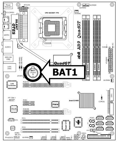
CMOS Backup Battery:
An onboard battery saves the CMOS memory to keep the BIOS information stays on even after disconnected your system with power source. Nevertheless, this backup battery exhausts after some five years. Once the error message like "CMOS BATTERY HAS Failed" or "CMOS checksum error" displays on monitor, this backup battery is no longer functional and has to be renewed.
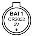
To renew the backup battery:
- Power off the system and disconnect with AC power source.
- Remove the exhausted battery.
- Insert a new CR2032 or equivalent battery. Pay attention to its polarity. The "+" side is its positive polarity.
- Connect AC power source and power on the system.
- Enter the BIOS setup menu. Reconfigure the setup parameters if necessary.
CAUTION:
Danger of explosion may arise if the battery is incorrectly renewed.
Renew only with the same or equivalent type recommended by the battery manufacturer.
※ Dispose of used batteries according to the battery manufacturer's instructions.
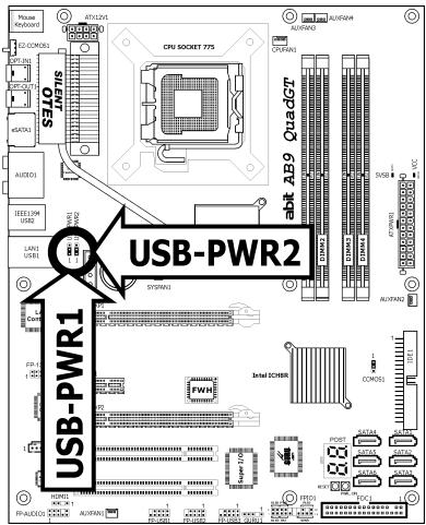
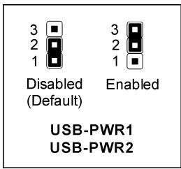
1.5.2 Wake-up Header
These headers use a jumper cap to enable/disable the wake-up function.
USB-PWR1:
Pin 1-2 shorted (Default): Disable wake-up function support at USB1 port.
Pin 2-3 shorted: Enable wake-up function support at USB1 port.
USB-PWR2:
Pin 1-2 shorted (Default): Disable wake-up function support at USB2 port.
Pin 2-3 shorted: Enable wake-up function support at USB2 port
1.6 Connecting Chassis Components
1.6.1 ATX Power Connectors
These connectors provide the connection from an ATX power supply. As the plugs from the power supply fit in only one orientation, find the correct one and push firmly down into these connectors.
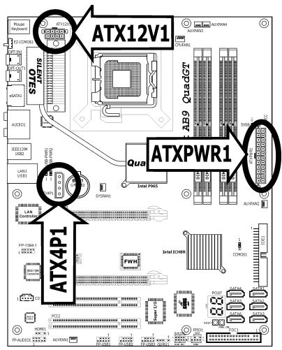
ATXPWR1: ATX 24-Pin Power Connector
The power supply with 20-pin or 24-pin cables can both be connected to this 24-pin connector. Connect from pin-1 for either type. However, a 20-pin power supply may cause the system unstable or even unbootable for the sake of insufficient electricity. A minimum power of 300W or higher is recommended.
ATX12V1: ATX 12V 8-Pin Power Connector
This connector supplies power to CPU. The system will not start without connecting power to this one.
ATX4P1: Auxiliary 12V Power Connector
This connector provides an auxiliary power source for devices added on PCI Express slots.
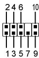
1.6.2 Front Panel Switches & Indicators Headers
This header is used for connecting switches and LED indicators on the chassis front panel.
Watch the power LED pin position and orientation. The mark "+" align to the pin in the figure below stands for positive polarity for the LED connection. Please pay attention when connecting these headers. A wrong orientation will only result in the LED not lighting, but a wrong connection of the switches could cause system malfunction.
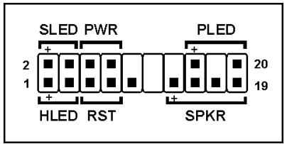
HLED (Pin 1, 3):
Connects to the HDD LED cable of chassis front panel.
RST (Pin 5, 7):
Connects to the Reset Switch cable of chassis front panel.
SPKR (Pin 13, 15, 17, 19):
Connects to the System Speaker cable of chassis.
- SLED (Pin 2, 4):
Connects to the Suspend LED cable (if there is one) of chassis front panel.
PWR (Pin 6, 8):
Connects to the Power Switch cable of chassis front panel.
PLED (Pin 16, 18, 20):
Connects to the Power LED cable of chassis front panel.
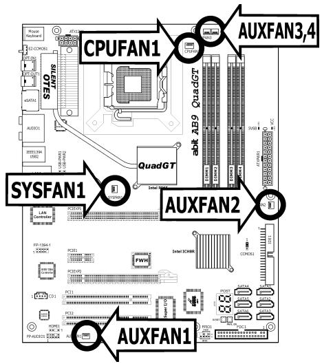
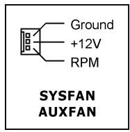
1.6.3 FAN Power Connectors
These connectors each provide power to the cooling fans installed in your system.
- CPUFAN1: CPU Fan Power Connector
- SYSFAN1: System Fan Power Connector
AUXFAN1~4: Auxiliary Fan Power Connector
These fan connectors are not jumpers. DO NOT place jumper caps on these connectors.
1.6.4 abit Silent OTES™ Technology
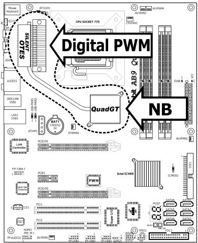
The abit Silent OTES™ Technology tremendously condenses and dissipates the heatwave generated together from both the NB chipset and the digital PWM modules via a fin-type heatsink that is supposed to be fanned outward by the air flowed from the CPU cooler. DO NOT remove this heatsink.
Please take into consideration of the amount of high temperature that could possibly generated from the PWM modules if you intend to alter this design.
1.7 Installing Hardware
※ DO NOT scratch the motherboard when installing hardware. An accidental scratch of a tiny surface-mount component may seriously damage the motherboard.
※ In order to protect the contact pins, please pay attention to these notices:
- A maximum 20 cycles of CPU installation is recommended.
- Never touch the contact pins with fingers or any object.
- Always put on the cap when the CPU is not in use.
1.7.1 CPU Socket 775
The installation procedures vary with different types of CPU fan-and-heatsink assembly. The one shown here is served for demo only. For detailed information on how to install the one you bought, refer to its installation guidelines.
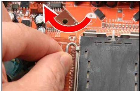
1. Place the board so that the lever-hook of the socket is on your left side. Use your left thumb and forefinger to hold the lever hook, pull it away from the retention tab. Rotate the lever to fully open position.
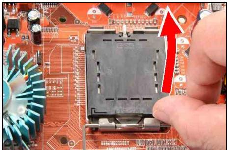
2. Use your right-thumb to raise the load plate. Lift it up to fully open position.
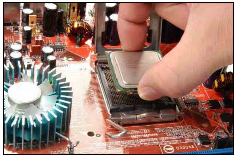
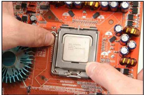
3. Use your right thumb and forefinger to grasp the CPU package. Be sure to grasp on the edge of the substrate, and face the Pin-1 indicator toward the bottom-left side. Aim at the socket and place the CPU package vertical down into the socket.
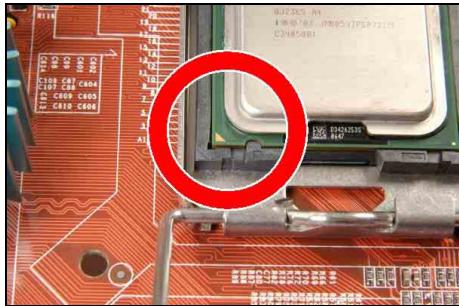
4. Visually inspect if the CPU is seated well into the socket. The alignment key must be located in the notch of package.
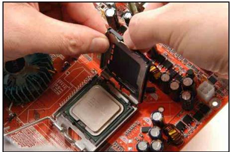
- Use your left hand to hold the load plate, and use your right thumb to peel the cap off.
The cap plays an important role in protecting contact pins. In order to prevent bent pin, PUT ON the cap after operation or testing.
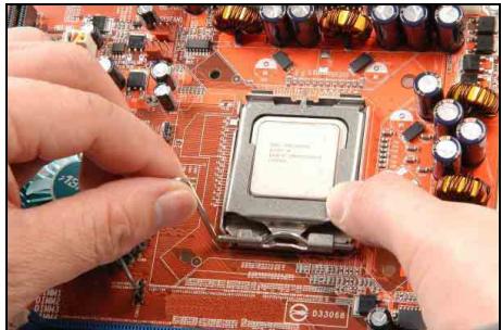
- Lower the plate onto the CPU package. Engage the load lever while gently pressing down the load plate.
- Secure the lever with the hook under retention tab.
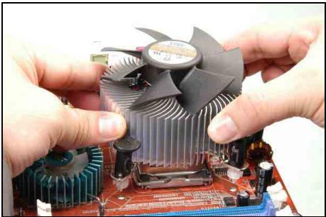
- Place the heatsink and fan assembly onto the socket. Align the four fasteners toward the four mounting holes on the motherboard.
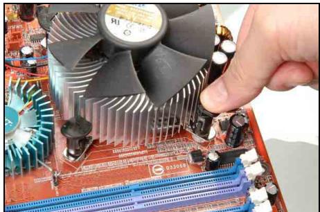
- Press each of the four fasteners down into the mounting holes. Rotate the fastener clock-wise to lock the heatsink and fan assembly into position.
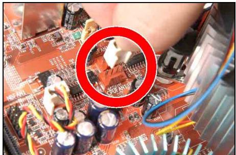
- Attach the four-pin power plug from the heatsink and fan assembly to the CPU FAN connector.
A higher fan speed will be helpful for better airflow and heat-dissipation. Nevertheless, stay alert to not touch any heatsink since a high temperature generated by the working system is still possible.
1.7.2 DDR2 Memory Slots
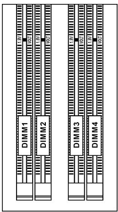
- To reach the optimum performance in dual-channel configurations, install identical DDR2 DIMM pairs for each channel.
- Install DIMMs with the same CAS latency. To reach the optimum compatibility, obtain memory modules from the same vendor.
Usually there is no hardware or BIOS setup required after adding or removing memory modules, but you will have to clear the CMOS memory first if any memory module related problem occurs.
To install system memory:
- Power off the computer and unplug the AC power cord before installing or removing memory modules.
- Locate the DIMM slot on the board.
- Hold two edges of the DIMM module carefully, keep away from touching its connectors.
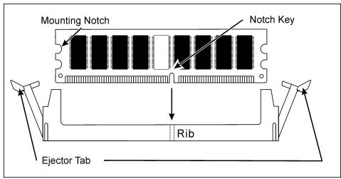
- Align the notch key on the module with the rib on the slot.
- Firmly press the module into the slots until the ejector tabs at both sides of the slot automatically snap into the mounting notch. Do not force the DIMM module in with extra force as the DIMM module only fits in one direction.
- To remove the DIMM modules, push the two ejector tabs on the slot outward simultaneously, and then pull out the DIMM module.
Static electricity can damage the electronic components of the computer or optional boards. Before starting these procedures, ensure that you are discharged of static electricity by touching a grounded metal object briefly.
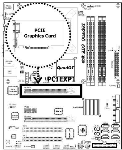
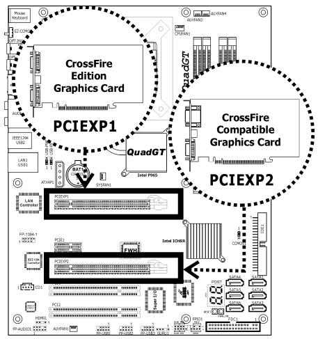
1.7.3 PCI Express X16 Add-on Slots (Install Graphics Card)
These slots support the connections of graphics cards that comply with PCI Express specifications. This motherboard provides dual PCI-Express X16 slots for one or two graphics cards installation:
One PCIE graphics card installation (Normal Mode):
Insert your PCIE graphics card into slot [PCIEXP1].
※ It is not recommended to install only one PCIE graphics card on the [PCIEXP2] slot, for such will pull the speed down to x4 only.
Two PCIE graphics cards installation (CrossFire Mode):
Install one CrossFire™ Edition graphics card into [Master] slot (the slot PCIEXP1 on this motherboard), and one CrossFire™ Compatible graphics card into [Slave] slot (the slot PCIEXP2 on this motherboard).
The ATI CrossFire technology currently supports the Microsoft Windows XP with Service Pack 2 only.
To enable CrossFire Mode, you will need to:
- Prepare one CrossFire™ Edition graphics card and one CrossFire™ Compatible graphics card.
-
Make sure the graphics card driver supports the ATI CrossFire™ technology. Download the latest driver from ATI website (http://www.ati.com).
Make sure your power supply unit is sufficient to provide the minimum power required. -
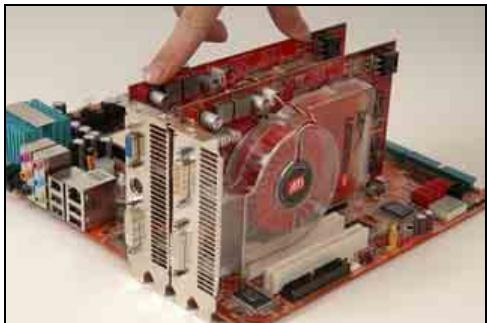
Insert the CrossFire™ Edition graphics card [Master Card] into the [PCIEXP1] master slot on motherboard.
- Insert the CrossFire™ compatible PCI Express graphics card (Slave Card) into the [PCIEXP2] slave slot.
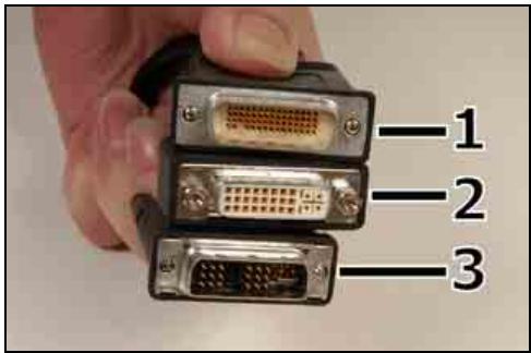
- There are 3 connectors on the DMS-59™-to-interconnect cable:
Connector 1: [DMS-59] Male connector
Connector 2: [DVI-I] Female connector
Connector 3: [DVI-I] Male connector
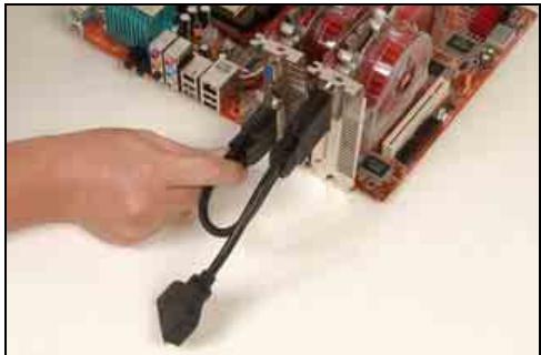
- Connect the DMS-59™ Male plug to the DMS-59™ connector on Master Card.
- Connect the DVI-I Male-end to the DVI-I connector on Salve Card.
- Connect the video output to your monitor from the remaining DVI-I Female-end.
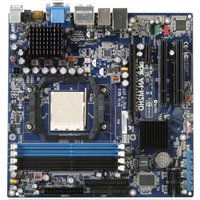
The motherboard in this illustration is served for demonstration only, may not be the same type or model as the one described in this user's manual.
1.8 Connecting Peripheral Devices
1.8.1 Floppy and IDE Disk Drive Connectors
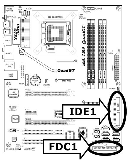
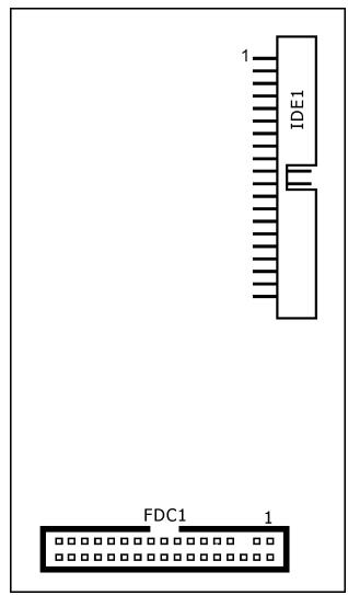
The FDC1 connector connects up to two floppy drives with a 34-wire, 2-connector floppy cable. Connect the single end at the longer length of ribbon cable to the FDC1 on the board, the two connectors on the other end to the floppy disk drives connector. Generally you need only one floppy disk drive in your system.
The red line on the ribbon cable must be aligned with pin-1 on both the FDC1 port and the floppy connector.
Each of the IDE port connects up to two IDE drives at Ultra ATA/100 mode by one 40-pin, 80-conductor, and 3-connector Ultra ATA/66 ribbon cables.
Connect the single end (blue connector) at the longer length of ribbon cable to the IDE port of this board, the other two ends (gray and black connector) at the shorter length of the ribbon cable to the connectors of your hard drives.
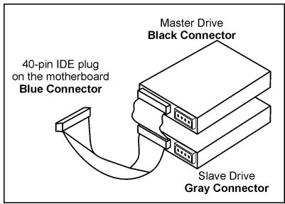
※ Make sure to configure the "Master" and "Slave" relation before connecting two drives by one single ribbon cable. The red line on the ribbon cable must be aligned with pin-1 on both the IDE port and the hard-drive connector.
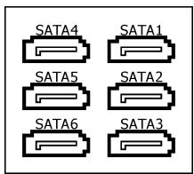
1.8.2 Serial ATA Connectors
Each SATA connector serves as one single channel to connect one SATA device by SATA cable.
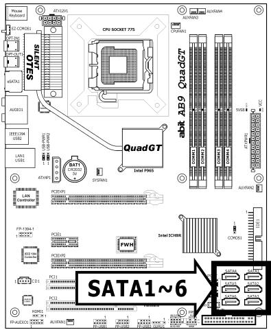
To connect SATA device:
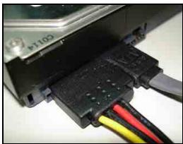
- Attach either end of the signal cable to the SATA connector on motherboard. Attach the other end to the SATA device.
- Attach the SATA power cable to the SATA device and connect the other end from the power supply.
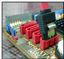
The motherboard in this photo is served for DEMO only, and may not be the same type or model as the one described in this user's manual.
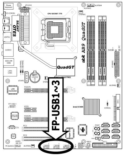
1.8.3 Additional USB 2.0 Port Headers
Each header supports 2x additional USB 2.0 ports by connecting bracket or cable to the rear I/O panel or the front-mounted USB ports of your chassis.
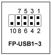
| Pin | Pin Assignment | Pin | Pin Assignment |
| 1 | VCC | 2 | VCC |
| 3 | Data0 - | 4 | Data1 - |
| 5 | Data0 + | 6 | Data1 + |
| 7 | Ground | 8 | Ground |
| 10 | NC |
※ Make sure the connecting cable bears the same pin assignment.
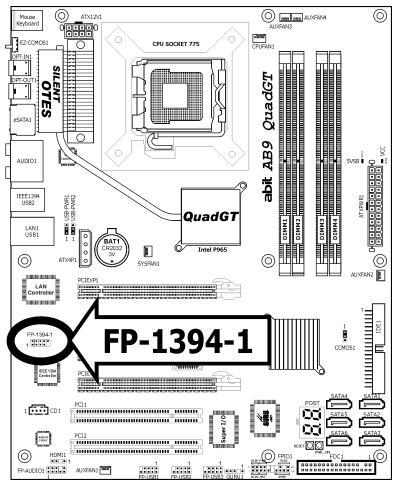
1.8.4 Additional IEEE1394 Port Header
Each header supports 1x additional IEEE1394 port by connecting bracket or cable to the rear I/O panel or the front-mounted IEEE1394 port of your chassis.
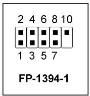
| Pin | Pin Assignment | Pin | Pin Assignment |
| 1 | TPA0 + | 2 | TPA0 - |
| 3 | Ground | 4 | Ground |
| 5 | TPB0 + | 6 | TPB0 - |
| 7 | +12V | 8 | +12V |
| 10 | Ground |
※ Make sure the connecting cable bears the same pin assignment.
1.8.5 Internal Audio Connectors
This connector connects to the audio output of internal CD-ROM drive or add-on card.
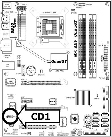

CD1
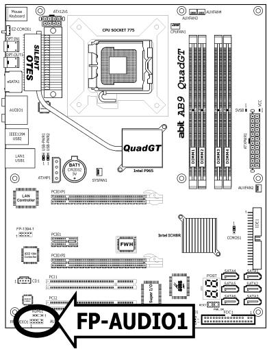
1.8.6 Front Panel Audio Connection Header
This header provides the front panel connection for HD (High Definition) Audio, yet for AC'97 Audio CODEC connection, you must carefully check the pin assignment before connecting from the front panel module. An incorrect connection may cause malfunction or even damage the motherboard.
FP-AUDIO1
Please do not connect the "Ground" cable or "USB VCC" cable from the front panel module to the Pin 4 "AVCC" of this header.
| Pin | Pin Assignment (HD AUDIO) |
| 1 | MIC2 L |
| 2 | AGND |
| 3 | MIC2 R |
| 4 | AVCC |
| 5 | FRO-R |
| 6 | MIC2_JD |
| 7 | F_IO_SEN |
| 9 | FRO-L |
| 10 | LINE2_JD |
| Pin | Pin Assignment (AC'97 AUDIO) |
| 1 | MIC In |
| 2 | GND |
| 3 | MIC Power |
| 4 | NC |
| 5 | Line Out (R) |
| 6 | NC |
| 7 | NC |
| 9 | Line Out (L) |
| 10 | NC |
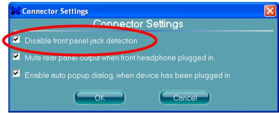
Driver Configuration for AC'97 audio connection:
The audio driver is originally configured to support HD Audio. For AC'97 audio connection, you may:
- Right-click the "Realtek HD Audio Manager" icon in system tray.

- Click "Audio I/O" tab, and then click "Connector Settings".
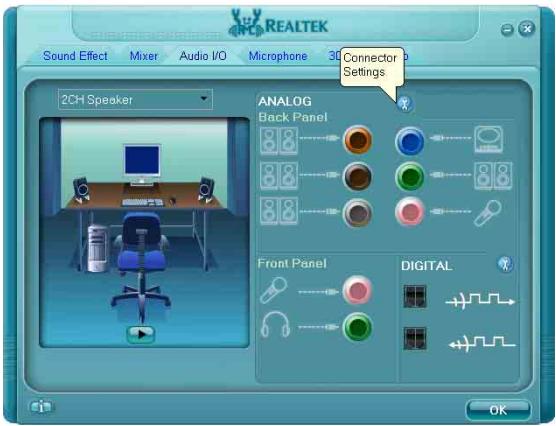
- Click "Disabled front panel jack detection", and then click "OK" to confirm.
1.8.7 S/PDIF Output Connection Header
This header provides the S/PDIF output connection to your add-on HDMI VGA card.
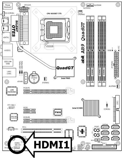
| Pin | Pin Assignment |
| 1 | VCC (5V) |
| 2 | x |
| 3 | S/PDIF Out |
| 4 | Ground |
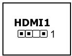
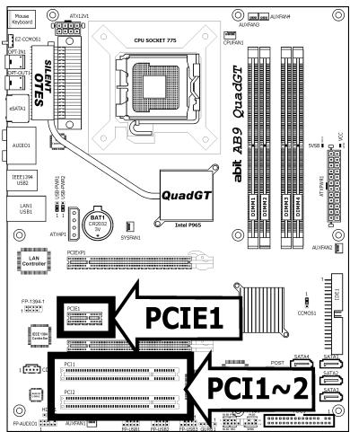
1.8.8 PCI and PCI Express X1 Slot
Install PCI Express X1 card into slot "PCIE1".
Install PCI cards into slots "PCI1" and/or "PCI2".
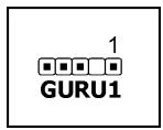
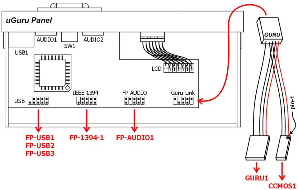
1.8.9 Guru Panel Connection Header
This header is reserved for connecting abit's exclusive Guru Panel. For more information, please refer to the included Guru Panel Installation Guide.
1.9 Onboard Indicators and Buttons
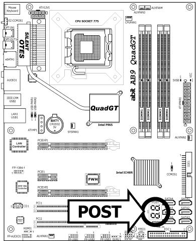
1.9.1 POST Code Displayer
This is an LED device to display the "POST" Code, the acronym for Power On Self Test. The computer will execute the POST action whenever you power on the computer. The POST process is controlled by the BIOS. It is used to detect the status of the computer's main components and peripherals. Each POST Code corresponds to different checkpoints that are also defined by the BIOS in advance. For example, "memory presence test" is an important checkpoint and its POST Code is "C1". When the BIOS execute any POST item, it will write the corresponding POST Code into the address 80h. If the POST passes, the BIOS will process the next POST item and write the next POST Code into the address 80h. If the POST fails, we can check the POST Code in address 80h to find out where the problem lies.
This LED device also displays the "POST" Code of AC2005, an "uGuru" chipset developed exclusively by abit.
※ The decimal point lights up during the AC2005 POST action.
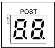
See Appendix for both AWARD and AC2005 POST Code definitions.
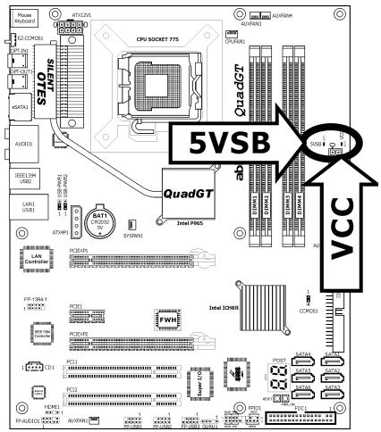
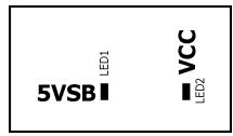
1.9.2 Power Source Indicators
5VSB: This LED lights up when the power supply is connected with power source.
VCC: This LED lights up when the system power is on.
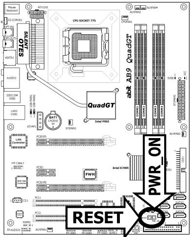
1.9.3 Onboard Buttons
- PWR_ON: Push this button to power on the system.
- RESET: Push this button to reset the system.

1.10 Connecting Rear Panel I/O Devices
The rear I/O part of this motherboard provides the following I/O ports:
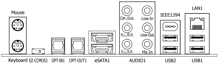
- Mouse: Connects to PS/2 mouse.
Keyboard: Connects to PS/2 keyboard. - EZ-CCMOS1: This switch enables clearing the CMOS memory without uncovering the system chassis.
To clear the CMOS memory by EZ-CCMOS1:
Step 1: Power off the system.
Step 2: Turn left this switch to the "Clear CMOS" position.
Step 3: Turn right this switch to its default "Normal" position. The default CMOS memory is now reloaded.
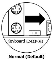
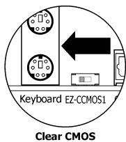
※ The C.C. POST Code appears when either the external "EZ-CCMOS1" switch or the internal "CCMOS1" jumper is not set to its normal position.
- OPT-IN1: This connector provides an S/PDIF-In connection through optical fiber to digital multimedia devices.
- OPT-OUT1: This connector provides an S/PDIF-Out connection through optical fiber to digital multimedia devices.
eSATA1: This connector supports the external SATA connection.
AUDIO1:
Cen./Sub. (Center / Subwoofer): Connects to the center and subwoofer channel in the 7.1 channel audio system.
R.L./R.R. (Rear Left / Rear Right): Connects to the rear left and rear right channel in the 7.1 channel audio system.
S.L./S.R. (Surround Left / Surround Right): Connects to the surround left and surround right channel in the 7.1 channel audio system.
Line-In: Connects to the line out from external audio sources.
Line-Out: Connects to the front left and front right channel in the 7.1-channel or regular 2-channel audio system.
Mic-In: Connects to the plug from external microphone.
LAN1: Connects to Local Area Network.
- IEEE1394: Connects to devices of IEEE1394 protocol.
- USB1/USB2: Connects to USB devices such as scanner, digital speakers, monitor, mouse, keyboard, hub, digital camera, joystick etc.

2. BIOS Setup
This motherboard provides a programmable EEPROM so that you can update the BIOS utility. The BIOS (Basic Input/Output System) is a program that deals with the basic level of communication between processor and peripherals. Use the BIOS Setup program only when installing motherboard, reconfiguring system, or prompted to "Run Setup". This chapter explains the Setup Utility of BIOS utility.
After powering up the system, the BIOS message appears on the screen, the memory count begins, and then the following message appears on the screen:
PRESS DEL TO ENTER SETUP
If this message disappears before you respond, restart the system by pressing <Ctrl> + <Alt> + <Del> keys, or by pressing the Reset button on the computer chassis. Only when these two methods fail should you restart the system by powering it off and then back on.
After pressing <Del> key, the main menu screen appears.
| Phoenix - AwardBIOS CMOS Setup Utility | |
| uGuru Utility | PnP/PCI Configurations |
| Standard CMOS Features | Load Fail-Safe Defaults |
| Advanced BIOS Features | Load Optimized Defaults |
| Advanced Chipset Features | Set Password |
| Integrated Peripherals | Save & Exit Setup |
| Power Management Setup | Exit Without Saving |
| Esc: Quit | ↑↓→← : Select Item |
| F10: Save & Exit Setup | (i965-W627EHG-6A79LA1EC-10) |
| F6: Save PROFILE To BIOS | F7: Load PROFILE From BIOS |
| Change CPU's Clock & Voltage | |

In order to increase system stability and performance, our engineering staff is constantly improving the BIOS menu. The BIOS setup screens and descriptions illustrated in this manual are for your reference only, and may not completely match with what you see on your screen.
2.1 μGuru™ Utility
There are two setup menus in this μGuru utility. You may switch between these two by clicking the left or right arrow key on keyboard:
2.1.1 OC Guru
| μGuru Utility v1.01C | |
| OC Guru | |
| Genuine Intel(R) CPU 3.60GHzFrequency : 3672MHzCPU Operating Speed X - External Clock X - Multiplier Factor X - Estimated New CPU Clock X - N/B Strap CPU As X - DRAM Spec. (CPU:DRAM) X - Estimated New DRAM Clock X - PCI Express Clock | Item Help ▷ |
| ▶ Voltages ControlPower Cycle Statistics | Press EnterPress Enter |
Genuine Intel(R) CPU
This item displays the CPU model name installed on this motherboard.
Frequency
This item displays the processor speed of the CPU installed on this motherboard.
CPU Operating Speed
This item displays the CPU operating speed according to the type and speed of your CPU. You can also select the [User Define] option to enter the manual option.
User Define:
The wrong settings of the multiplier and external clock in certain circumstances may cause CPU damage. Setting the working frequency higher than the PCI chipset or processor specs, may cause abnormal memory module functioning, system hangs, hard disk drive data lose, abnormal functioning of the VGA card, or abnormal functioning with other add-on cards. Using non-specification settings for your CPU is not the intention of this explanation. These should be used for engineering testing, not for normal applications.
※ There will be no guaranty for the settings beyond specification. Any damage of any component on this motherboard or peripherals resulting therein is not our responsibility.
External Clock
This item selects the external clock frequency. Due to the specification limit of the CPU you installed, the speed you set over its standard bus speed is supported, but not guaranteed.
Multiplier Factor
This item displays the multiplier factor for the CPU you installed.
- Estimated New CPU Clock
This item displays an estimated CPU processor speed.
N/B Strap CPU As
This item sets the external hardware reset strap assigned to MCH (Memory Controller Hub).
DRAM Spec. (CPU:DRAM)
This item determines the DRAM frequency.
- Estimated New DRAM Clock
This item displays an estimated DRAM speed.
Voltages Control
This option allows you to switch between the default and user-defined voltages. Leave this setting at default unless the current voltage setting cannot be detected or is not correct. The option "User Define" enables you to select the following voltages manually.
CPU Core Voltage
DDR2 Voltage
CPU VTT 1.2V Voltage
- MCH 1.25V Voltage
- ICH 1.05V Voltage
- ICHIO 1.5V Voltage
DDR2 Reference Voltage
Power Cycle Statistics
Click
| pGuru Utility v1.01C | |
| OC Guru | |
| Power Cycle Statistics | |
| PC Up Time | 0 Hours |
| PC Up Time Total | 119 Hours |
| PC Power Cycles | 538 Cycles |
| PC Reset Button Cycles | 123 Cycles |
| AC Power On Total Time | 288 Hours |
| AC Power Cycles | 228 Cycles |
| ↑↓→←:Move Enter:Select +/-/PU/PD:Value F8:OC On The Fly F10:Save ESC:Exit | |
These items display the power cycle statistics for each element.
2.1.2 ABIT EQ
Click right-arrow < > key to switch from OC Guru setup menu to ABIT EQ setup menu:
| μGuru Utility v1.01C | ||
| ABIT EQ | ||
| ABIT EQ Beep Control | Enabled | Item Help ▷ |
| LED Effect Control | ALL ON | |
| Temperature Monitoring | Press Enter | |
| Voltage Monitoring | Press Enter | |
| Fan Speed Monitoring | Press Enter | |
| FanEQ Control | Press Enter | |
| ↑↓→←:Move Enter:Select +/-/PU/PD:Value | F10:Save ESC:Exit | |
ABIT EQ Beep Control
This item controls if the beeper sounds or not when any warning event occurred.
LED Effect Control
This item selects the displaying mode for all the LEDs located at the bottom side of the motherboard.
[All OFF]: All the LED lights off.
[All ON]: All the LED lights on without any flashing effect.
[MODE 1 ~ MODE 7]: All the LED lights on with the flashing effect by one of these modes.

Temperature Monitoring
Click
| μGuru Utility v1.01C | |||||
| ABIT EQ | |||||
| Temperature Monitoring | |||||
| Reading | Shutdown Enable | Shutdown Temp. | Beep Enable | Beep Temp. | |
| (*)CPU Temperature | 59°C/138°F | (*) | 85°/185°F | (*) | 75°C/167°F |
| (*)System Temperature | 42°C/107°F | () | 65°C/149°F | (*) | 55°C/131°F |
| (*)PWM Phase1 Temperature | 60°C/140°F | () | 135°C/275°F | (*) | 125°C/257°F |
| (*)PWM Phase2 Temperature | 60°C/140°F | () | 135°C/275°F | (*) | 125°C/257°F |
| (*)PWM Phase3 Temperature | 60°C/140°F | () | 135°C/275°F | (*) | 125°C/257°F |
| (*)PWM Phase4 Temperature | 60°C/140°F | () | 135°C/275°F | (*) | 125°C/257°F |
| (*)PWM Phase5 Temperature | 60°C/140°F | () | 135°C/275°F | (*) | 125°C/257°F |
| (*)PWM Average Current | 64 A | ||||
| (*)PWM Peak Current | 64 A | ||||
| ↑↓→←:Move Enter:Select +/-/PU/PD:Value | F10:Save | ESC:Exit | |||
CPU, System, PWM1~5 Temperature/PWM Current
These items display the temperature of CPU, System, and Power Module. Both the average and peak current of PWM will be displayed as well.
- Shutdown Enable
Use
- Shutdown Temp.
This items sets the temperature that will shutdown the system automatically in order to prevent system overheating.
- Beep Enable
Use
- Beep Temp.
This item selects the warning temperature limit.
The shutdown temperature must be set above the warning temperature.
Click
| μGuru Utility v1.01C | |||||
| ABIT EQ | |||||
| Voltage Monitoring | |||||
| Reading | Shutdown Enable | Beep Enable | High Limit | Low Limit | |
| (*)CPU Core Voltage | 1.32 | V (*) | (*) | 1.65 V | 0.00 V |
| (*)DDR2 Voltage | 1.80 | V ( ) | (*) | 2.15 V | 1.45 V |
| (*)DDR2 VTT Voltage | 0.89 | V ( ) | (*) | 1.05 V | 0.70 V |
| (*)CPU VTT 1.2V Voltage | 1.20 | V ( ) | (*) | 1.45 V | 0.95 V |
| (*)MCH 1.25V Voltage | 1.25 | V ( ) | (*) | 1.50 V | 1.00 V |
| (*)ICHIO 1.5V Voltage | 1.50 | V ( ) | (*) | 1.80 V | 1.20 V |
| (*)ICH 1.05V Voltage | 1.05 | V ( ) | (*) | 1.25 V | 0.85 V |
| (*)ATX +12V (24-Pin Connector) | 12.00 | V ( ) | (*) | 14.40 V | 9.60 V |
| (*)ATX +12V (4-Pin Connector) | 12.00 | V ( ) | (*) | 14.40 V | 9.60 V |
| (*)ATX +5V | 5.00 | V ( ) | (*) | 6.00 V | 4.00 V |
| (*)ATX +3.3V | 3.30 | V ( ) | (*) | 3.95 V | 2.65 V |
| (*)ATX 5VSB | 5.00 | V ( ) | (*) | 6.00 V | 4.00 V |
| ↑↓→←:Move Enter:Select +/-/PU/PD:Value F10:Save ESC:Exit | |||||
All Voltages
These items display the voltage of each element.
- Shutdown Enable
Use
- Beep Enable
Use
High/Low Limit
These items set the high and low voltage limit.
The value of high limit must be set above the one of low limit.

Fan Speed Monitoring
Click
| μGuru Utility v1.01C | ||||
| ABIT EQ | ||||
| Fan Speed Monitoring | ||||
| Reading | Shutdown Enable | Beep Enable | Low Limit | |
| (*)CPU FAN Speed | 2440 RPM | (*) | (*) | 300 RPM |
| ()SYS FAN Speed | N/A | () | () | 300 RPM |
| ()AUX1 FAN Speed | N/A | () | () | 300 RPM |
| ()AUX2 FAN Speed | N/A | () | () | 300 RPM |
| ()AUX3 FAN Speed | N/A | () | () | 300 RPM |
| ()AUX4 FAN Speed | N/A | () | () | 300 RPM |
| ↑↓→←:Move Enter:Select +/-/PU/PD:Value | F10:Save | ESC:Exit | ||
CPU/SYS/AUX1~4 FAN Speed
These items display the speed of the fans connected to CPU, SYS, and AUX1~4 fan connectors.
- Shutdown Enable
Use
- Beep Enable
Use
- Low Limit
These items set the low limit of fan speed.
| μGuru Utility v1.01C | |
| ABIT EQ | |
| FanEQ Control | |
| ► 1st FanEQ Group | Press Enter |
| ► 2nd FanEQ Group | Press Enter |
| ↑↓→←:Move Enter:Select +/-/PU/PD:Value F10:Save ESC:Exit | |

1st FanEQ Group
Click
| μGuru Utility v1.01C | ||
| ABIT EQ | ||
| 1st FanEQ Group | ||
| CPU FanEQ Control | Enabled | Item Help ▷□ |
| -Reference Temperature | CPU Temperature | |
| -Control Temperature High | 66°C/150°F | |
| -Control Temperature Low | 56°C/132°F | |
| -Fan PWM Duty Cycle High | 100 % | |
| -Fan PWM Duty Cycle Low | 60 % | |
| SYS FanEQ Control | Enabled | |
| -Reference Temperature | SYS Temperature | |
| -Control Temperature High | 40°C/104°F | |
| -Control Temperature Low | 30°C/86°F | |
| -DC Fan Voltage High | 12.0 V | |
| -DC Fan Voltage Low | 8.0 V | |
| AUX1 FanEQ Control | Enabled | |
| -Reference Temperature | SYS Temperature | |
| -Control Temperature High | 40°C/104°F | |
| -Control Temperature Low | 30°C/86°F | |
| -DC Fan Voltage High | 12.0 V | |
| -DC Fan Voltage Low | 8.0 V | |
| ↑↓→←:Move Enter:Select +/-/PU/PD:Value F10:Save ESC:Exit | ||
CPU/SYS/AUX1 FanEQ Control
When set to [Enabled], these items control the CPU, SYS, and/or AUX1 fan speed by the following setting combinations.
Reference Temperature
This item selects the reference point for taking temperature among the available options of CPU, SYS, and PWM Temperature, but there is only one "CPU Temperature" item to choose for the "CPU FanEQ Control".
- Control Temperature High/Low
These items set the high and low temperature limit that you want to do the fan speed control.
- Fan PWM Duty Cycle High/Low
These items set the high and low limit of PWM duty cycle that you want to provide the fan with.
DC Fan Voltage High/Low
These items set the high and low voltage limit that you want to provide the fan with.
The value of high limit must be set above the one of low limit.
2nd FanEQ Group
Click
| μGuru Utility V1.01C | ||
| ABIT EQ | ||
| 2nd FanEQ Group | ||
| AUX2 FanEQ Control | Enabled | Item Help ▷□ |
| -Reference Temperature | SYS Temperature | |
| -Control Temperature High | 40°C/104°F | |
| -Control Temperature Low | 30°C/86°F | |
| -DC Fan Voltage High | 12.0 V | |
| -DC Fan Voltage Low | 8.0 V | |
| AUX3 FanEQ Control | Disabled | |
| AUX4 FanEQ Control | Disabled | |
| ↑↓→←:Move Enter:Select +/-/PU/PD:Value | F10:Save ESC:Exit | |
AUX2\~AUX4 FanEQ Control
When set to [Enabled], these items control the AUX2~AUX4 fan speed by the following setting combinations.
Reference Temperature
This item selects the reference point for taking temperature among the available options of CPU, SYS, and PWM Temperature, but there is only one "CPU Temperature" item to choose for the "CPU FanEQ Control".
- Control Temperature High/Low
These items set the high and low temperature limit that you want to do the fan speed control.
DC Fan Voltage High/Low
These items set the high and low voltage limit that you want to provide the fan with.
The value of high limit must be set above the one of low limit.
2.2 Standard CMOS Features
| Phoenix - AwardBIOS CMOS Setup Utility Standard CMOS Features | ||
| Date (mm:dd:yy) | Wed, Dec 27 2006 | Item Help |
| Time (hh:mm:ss) | 12 : 34 : 56 | |
| ▶ SATA Channel 1 | None | |
| ▶ SATA Channel 2 | None | |
| ▶ SATA Channel 3 | None | |
| ▶ SATA Channel 4 | None | |
| ▶ SATA Channel 5 | None | |
| ▶ SATA Channel 6 | None | |
| Drive A | 1.44M, 3.5 in. | |
| Drive B | None | |
| Floppy 3 Mode Support | Disabled | |
| Halt On | All, But Keyboard | |
| Base Memory | 640K | |
| Extended Memory | 1047552K | |
| Total Memory | 1047552K | |
| ↑↓→←:Move Enter:Select +/-/PU/PD:Value F10:Save ESC:Exit F1:General Help F5: Previous Values F6: Fail-Safe Defaults F7: Optimized Defaults | ||
Date (mm:dd:yy)
This item sets the date you specify (usually the current date) in the format of [Month], [Date], and [Year].
Time (hh:mm:ss)
This item sets the time you specify (usually the current time) in the format of [Hour], [Minute], and [Second].

SATA Channel 1 ~ SATA Channel 6
Click
| Phoenix - AwardBIOS CMOS Setup Utility SATA Channel 1 | ||
| HDD Auto-Detection | Press Enter | Item Help |
| SATA Channel 1 | Auto | |
| Access Mode | Auto | |
| Capacity | 0 MB | |
| Cylinder | 0 | |
| Head | 0 | |
| Precomp | 0 | |
| Landing Zone | 0 | |
| Sector | 0 | |
| ↑↓→←:Move Enter:Select +/-/PU/PD:Value F10:Save ESC:Exit F1:General Help F5:Previous Values F6:Fail-Safe Defaults F7:Optimized Defaults | ||
| HDD Auto-Detection | ||
| This item allows you to detect the parameters of hard drives by pressing <Enter> key. The parameters will be shown on the screen automatically. | ||
| SATA Channel 1 ~ SATA Channel 6 | ||
| When set to [Auto], the BIOS will automatically check what kind of SATA hard drive you are using. If you want to define your own drive yourself, set it to [Manual] and make sure you fully understand the meaning of the parameters. Please refer to the instruction manual provided by the device's manufacturer to get the setting right. | ||
| Access Mode | ||
| This item selects the mode to access your SATA devices. Leave this item at its default [Auto] setting to detect the access mode of your HDD automatically. | ||
| Capacity | ||
| This item displays the approximate capacity of the disk drive. Usually the size is slightly greater than the size of a formatted disk given by a disk-checking program. | ||
| Cylinder | ||
| This item configures the numbers of cylinders. | ||
| Head | ||
| This item configures the numbers of read/write heads. | ||
| Precomp | ||
| This item displays the number of cylinders at which to change the write timing. | ||
| Landing Zone | ||
| This item displays the number of cylinders specified as the landing zone for the read/write heads. | ||
| Sector | ||
| This item configures the numbers of sectors per track. | ||
| Back to Standard CMOS Features Setup Menu | ||
| Drive A & Drive B | ||
| This item sets the type of floppy drives (usually only Drive A) installed. | ||
| Floppy 3 Mode Support | ||
| This item allows you to use "3 Mode Floppy Drive" in Japanese computer systems by selecting drive A, B, or both. Leave this item at its default [Disabled] setting if you are not using this Japanese standard floppy drive. | ||
| Halt On | ||
| This item determines whether the system stops if an error is detected during system boot-up. | ||
| [All Errors]: The system-boot will stop whenever the BIOS detect a non-fatal error. | ||
| [No Errors]: The system-boot will not stop for any error detected. | ||
[All, But Keyboard]: The system-boot will stop for all errors except a keyboard error.
[All, But Diskette]: The system-boot will stop for all errors except a diskette error.
[All, But Disk/Key]: The system-boot will stop for all errors except a diskette or keyboard error.
Base Memory
This item displays the amount of base memory installed in the system. The value of the base memory is typically 640K for systems with 640K or more memory size installed on the motherboard.
Extended Memory
This item displays the amount of extended memory detected during system boot-up.
Total Memory
This item displays the total memory available in the system.
2.3 Advanced BIOS Features
| Phoenix - AwardBIOS CMOS Setup Utility Advanced BIOS Features | ||
| CPU L3 Cache | Enabled | Item Help |
| ◆ CPU Feature | Press Enter | |
| ◆ Hard Disk Boot Priority | Press Enter | |
| Hyper-Threading Technology | Enabled | |
| Quick Power On Self Test | Enabled | |
| First Boot Device | Floppy | |
| Second Boot Device | Hard Disk | |
| Third Boot Device | SATA CDROM | |
| Boot Other Device | Enabled | |
| Boot Up Floppy Seek | Disabled | |
| Boot Up NumLock Status | On | |
| Security Option | Setup | |
| MPS Version Ctrl For OS | 1.4 | |
| Report No FDD for OS | No | |
| Full Screen Logo Show | Enabled | |
| ↑↓→←:Move Enter:Select +/-/PU/PD:Value F10:Save ESC:Exit F1:General Help F5: Previous Values F6: Fail-Safe Defaults F7: Optimized Defaults | ||
CPU L3 Cache
This item is used to enable the L3 cache (default setting), and appears only for certain CPU (Intel Pentium 4 processor with HT Technology Extreme Edition) that possesses L3 cache.

CPU Feature
Click
| Phoenix - AwardBIOS CMOS Setup Utility CPU Feature | ||
| Thermal Control | Enabled | Item Help |
| - Thermal Management | Thermal Monitor 1 | |
| Limit CPUID MaxVal | Disabled | |
| CIE Function | Enabled | |
| Execute Disable Bit | Enabled | |
| Virtualization Technology | Enabled | |
| EIST Function | Enabled | |
| ↑↓→←:Move Enter:Select +/-/PU/PD:Value F10:Save ESC:Exit F1:General Help F5: Previous Values F6: Fail-Safe Defaults F7: Optimized Defaults | ||
Thermal Control
This option enables or disables the thermal monitoring.
Thermal Management
This item selects the type of thermal monitoring.
Limit CPUID MaxVal
When set to [Enabled], this item limits the CPUID maximum value to 3, which is usually required for older OS like Windows NT4.0.
Leave this item at its default [Disabled] settings for OS like Windows XP.
C1E Function
This item appears only for certain processors with the C1E (Enhanced Halt State) Function. When set to [Enabled], the processor will further reduce the total power consumption.
Execute Disable Bit
This item appears only for certain processors with the Execute Disable Bit (XD bit) feature. When set to [Enabled], this item allows the processor to prevent data pages from being used by malicious software to execute code and provide memory protection.
Virtualization Technology
This option enables or disables the additional hardware capabilities provided by Virtualization Technology.
EIST Function
This item appears only for certain processors with the EIST (Enhanced Intel SpeedStep Technology) Function. When set to [Enabled], EIST will dynamically switch between multiple frequency and voltage points to optimize the power and performance balance of the processor and system based on demand.
Back to Advanced BIOS Features Setup Menu
Hard Disk Boot Priority
This item selects the hard disks booting priority. By pressing
This item functions only when there is the option of [Hard Disk] in any one of the First/Second/Third Boot Device items.
Hyper-Threading Technology
This item is used to enable the functionality of the processor with Hyper-Threading Technology and will appear only when using such processor.
The Hyper-Threading Technology helps your PC work more efficiently by maximizing processor resources and enabling a single processor to run two separate threads of software simultaneously, bringing forth greater performance and system responsiveness when running multiple applications at once.
Quick Power On Self Test
When set to [Enabled], this item speeds up the Power On Self Test (POST) after powering on the system. The BIOS shorten or skip some check during the POST.
| First Boot Device / Second Boot Device / Third Boot Device / Boot Other Device Select the drive to boot first, second and third in the [First Boot Device], [Second Boot Device], and [Third Boot Device] items respectively. The BIOS will boot the operating system according to the sequence of the drive selected. Set [Boot Other Device] to [Enabled] if you wish to boot from another device other than these three items. ※ Select the correct type of CD-ROM for the option [First Boot device] when installing OS from CD-ROM. |
| Boot Up Floppy Seek When set to [Enabled], the BIOS will check whether the floppy disk drive is installed or not. |
| Boot Up NumLock Status This item determines the default state of the numeric keypad at system booting up. [On]: The numeric keypad functions as number keys. [Off]: The numeric keypad functions as arrow keys. |
| Security Option This item determines when the system will prompt for password - every time the system boots or only when enters the BIOS setup. [Setup]: The password is required only when accessing the BIOS Setup. [System]: The password is required each time the computer boots up. ※ Don't forget your password. If you forget the password, you will have to open the computer case and clear all information in the CMOS before you can start up the system. But by doing this, you will have to reset all previously set options. |
| MPS Version Ctrl For OS This item specifies which version of MPS (Multi-Processor Specification) this motherboard will use. Leave this item at its default setting. |
| Report No FDD For OS When set to [Yes], this item allows you to run some older operating system without floppy disk drive. Leave this item at its default setting. |
| Full Screen LOGO Show This item determines to show the full screen logo when booting. |
2.4 Advanced Chipset Features
| Phoenix - AwardBIOS CMOS Setup Utility Advanced Chipset Features | ||
| DRAM Timing Selectable | By SPD | Item Help |
| X - CAS Latency Time (tCL) | Auto | |
| X - RAS# to CAS# Delay (tRCD) | Auto | |
| X - RAS# Precharge (tRP) | Auto | |
| X - Precharge Delay (tRAS) | Auto | |
| X - Command Rate | Auto | |
| X - Refresh Cycle Time (tRFC) | Auto | |
| PCI-E Compliancy Mode | V1.0a | |
| PEG Force X1 | Disabled | |
| Init Display First | PCI Slot | |
| ↑↓→←:Move Enter:Select +/-/PU/PD:Value F10:Save ESC:Exit F1:General Help F5: Previous Values F6: Fail-Safe Defaults F7: Optimized Defaults | ||
DRAM Timing Selectable
This item sets the optimal timings for the following four items, depending on the memory module you are using. The default setting "By SPD" configures these four items by reading the contents in the SPD (Serial Presence Detect) device. The EEPROM on the memory module stores critical parameter information about the module, such as memory type, size, speed, voltage interface, and module banks. The following items will be available to make adjustments by selecting option [Manual].
CAS Latency Time (tCL)
RAS# to CAS# Delay (tRCD)
RAS# Precharge (tRP)
Precharge Delay (tRAS)
Command Rate
Refresh Cycle Time (tRFC)
PCI-E Compliancy Mode
This item selects the mode for PCI Express add-on card.
PEG Force X1
When set to [Enabled], this item forces the PEG port down to x1 mode.
Init Display First
This item allows you to choose the primary display card.
2.5 Integrated Peripherals
| Phoenix - AwardBIOS CMOS Setup Utility Integrated Peripherals | ||
| ►OnChip IDE Device | Press Enter | Item Help |
| ►OnChip PCI Device | Press Enter | |
| ►Onboard PCI Device | Press Enter | |
| Onboard FDC Controller | Enabled | |
| ↑↓→←:Move Enter:Select +/-/PU/PD:Value F10:Save ESC:Exit F1:General Help F5:Previous Values F6:Fail-Safe Defaults F7:Optimized Defaults | ||

OnChip IDE Device
Click
| Phoenix - AwardBIOS CMOS Setup Utility OnChip IDE Device | |
| IDE Bus Master Enabled | Item Help |
| SATA Mode IDE | |
| ↑↓→←:Move Enter:Select +/-/PU/PD:Value F10:Save ESC:Exit F1:General Help F5:Previous Values F6:Fail-Safe Defaults F7:Optimized Defaults | |
IDE Bus Master
This option enables or disables the IDE bus mastering capability under the DOS environment.
SATA Mode
This item selects the mode for devices connected through SATA1~SATA6 ports.
[IDE]: The on-chip Serial ATA served as IDE mode.
[RAID]: The on-chip Serial ATA served as RAID mode.
[AHCI]: The on-chip Serial ATA served as AHCI (Advanced Host Controller Interface) mode for advanced performance and usability.
Click
| Phoenix - AwardBIOS CMOS Setup Utility OnChip PCI Device | ||
| OnChip USB Controller | Enabled | Item Help |
| - USB 2.0 Controller | Enabled | |
| - USB Keyboard Support | OS | |
| - USB Mouse Support | OS | |
| OnChip Audio Controller | Enabled | |
| ↑↓→←:Move Enter:Select +/-/PU/PD:Value F10:Save ESC:Exit F1:General Help F5: Previous Values F6: Fail-Safe Defaults F7: Optimized Defaults | ||
OnChip USB Controller
This option enables or disables the USB controller.
USB 2.0 Controller
This option enables or disables the USB 2.0 controller.
USB Keyboard Support
Select [BIOS] for the legacy operating system (such as DOS) that does not support USB keyboard.
- USB Mouse Support
Select [BIOS] for the legacy operating system (such as DOS) that does not support USB mouse.
OnChip Audio Controller
This option enables or disables the audio controller.
Click
| Phoenix - AwardBIOS CMOS Setup Utility Onboard PCI Device | ||
| Onboard 1394 Controller | Enabled | Item Help |
| Onboard LAN Controller | Enabled | |
| - Invoke Boot Agent | Disabled | |
| JMB363 SATA Controller | Enabled | |
| - Controller Mode | IDE | |
| ↑↓→←:Move Enter:Select +/-/PU/PD:Value F10:Save ESC:Exit F1:General Help F5:Previous Values F6:Fail-Safe Defaults F7:Optimized Defaults | ||
Onboard 1394 Controller
This option enables or disables the IEEE 1394 controller.
Onboard LAN Controller
This option enables or disables the LAN controller.
- Invoke Boot Agent
This item allows you to use the boot ROM (instead of a disk drive) to boot up the system and access the local area network directly.
JMB363 Controller
This option enables or disables the JMB363 controller that controls both IDE1 and eSATA1 ports.
- Controller Mode
This item selects the mode for devices connected through eSATA1 ports.
Options: [IDE], [RAID], [AHCI].

Back to Integrated Peripherals Setup Menu
Onboard FDC Controller
This option enables or disables the floppy disk controller.
2.6 Power Management Setup
| Phoenix - AwardBIOS CMOS Setup Utility Power Management Setup | ||
| ACPI Suspend Type | S3(Suspend To RAM) | Item Help |
| - Resume by USB from S3 | Enabled | |
| Power Button Function | Instant-Off | |
| Wake Up by Wake# of PCIe | Disabled | |
| Wake Up by PME# of PCI | Disabled | |
| Wake Up by Onboard LAN | Disabled | |
| Resume by Alarm | Disabled | |
| X - Date(of month) Alarm | 0 | |
| X - Time(hh:mm:ss) Alarm | 0 : 0 : 0 | |
| POWER ON Function | Button Only | |
| X - KB Power ON Password | Enter | |
| X - Hot Key Power ON | Ctrl-F1 | |
| Restore On AC Power Loss | Power Off | |
| ↑↓→←:Move Enter:Select +/-/PU/PD:Value F10:Save ESC:Exit F1:General Help F5: Previous Values F6: Fail-Safe Defaults F7: Optimized Defaults | ||
ACPI Suspend Type
This item selects the type of Suspend mode.
Resume by USB from S3
When set to [Enabled], this item allows you to use a USB device to wake up a system that is in the S3 (STR - Suspend To RAM) state. This item can be configured only if the item "ACPI Suspend Type" is set to [S3(STR)].
Power Button Function
This item selects the method of powering off your system:
[Delay 4 Sec.]: Pushing the power button for more than 4 seconds will power off the system. This will prevent the system from powering off in case you accidentally hit or pushed the power button.
[Instant-Off]: Pressing and then releasing the power button at once will immediately power off the system.
Wake Up by Wake# of PCIe
When set to [Enabled], access through the add-on PCI Express card can remotely wake up the system that was in Soft-Off condition. The PCI Express card must support the wake up function.
Wake Up by PME# of PCI
When set to [Enabled], access through the add-on PCI card can remotely wake up the system that was in Soft-Off condition. The PCI card must support the wake up function.
Wake Up by Onboard LAN
When set to [Enabled], access through the onboard LAN port can remotely wake up the system that was in Soft-Off condition.
Resume by Alarm
When set to [Enabled], you can set the date and time you would like the Soft-Off PC to power-on in the "Date (of Month) Alarm" and "Time (hh:mm:ss) Alarm" items. However, if the system is being accessed by incoming calls or the network (Resume On Ring/LAN) prior to the date and time set in these items, the system will give priority to the incoming calls or network instead.
- Date (of Month) Alarm
[0]: This option power-on the system everyday according to the time set in the "Time (hh:mm:ss) Alarm" item.
[1-31]: This option selects a date you would like the system to power-on. The system will power-on on the date set, and the time set in the "Time (hh:mm:ss) Alarm" item.
Time (hh:mm:ss) Alarm
This item sets the time you would like the system to power-on.
POWER ON Function
This item selects the way you want your system to power on.
[Password]: Use a password to power on the system, select this option then press
[Hot KEY]: Use any of the function keys between <F1> to <F12> to power on the system.
[Mouse Left]: Double click the mouse left button to power on the system.
[Mouse Right]: Double click the mouse right button to power on the system.
[Any KEY]: Use any keyboard keys to power on the system.
[Button Only]: Use only the power button to power on the system.
[Keyboard 98]: Use the power-on button on the "Keyboard 98" compatible keyboard to power on the system.
The mouse wake up function can only be used with the PS/2 mouse, not with the COM port or USB type. Some PS/2 mice cannot wake up the system because of compatible problems. If the specs of your keyboard are too old, it may fail to power on.
KB Power ON Password
This item sets the password required in order to power on your computer.
※ Do not forget your password, or you will have to clear the CMOS and reset all parameters in order to utilize this function again.
Hot Key Power ON
This item powers on the system by pressing Ctrl key plus one of each function key ( F1 F12 ) simultaneously.
Restore On AC Power Loss
This item selects the system action after an AC power failure.
[Power Off]: When power returns after an AC power failure, the system's power remains off. You must press the Power button to power-on the system.
[Power On]: When power returns after an AC power failure, the system's power will be powered on automatically.
[Last State]: When power returns after an AC power failure, the system will return to the state where you left off before power failure occurred. If the system's power is off when AC power failure occurs, it will remain off when power returns. If the system's power is on when AC power failure occurs, the system will power-on when power returns.
2.7 PnP/PCI Configurations
| Phoenix - AwardBIOS CMOS Setup Utility PnP/PCI Configurations | ||
| Resources Controlled By X - IRQ Resources PCI/VGA Pallete Snoop ** PCI Express relative items | Auto(ESCD) Press Enter Disbaled | Item Help |
| ↑↓→←:Move Enter:Select +/-/PU/PD:Value F10:Save ESC:Exit F1:General Help F5:Previous Values F6:Fail-Safe Defaults F7:Optimized Defaults | ||
Resources Controlled By
This item configures all of the boot and Plug-and-Play compatible devices.
[Auto(ESCD)]: The system will automatically detect the settings.
[Manual]: Choose the specific IRQ resources in the "IRQ Resources" menu.
- IRQ Resources
Click
This item sets each system interrupt to either [PCI Device] or [Reserved].
| Phoenix - AwardBIOS CMOS Setup Utility - IRQ Resources | ||
| IRQ-4 assigned to | PCI Device | Item Help |
| IRQ-5 assigned to | PCI Device | |
| IRQ-7 assigned to | PCI Device | |
| IRQ-10 assigned to | PCI Device | |
| IRQ-11 assigned to | PCI Device | |
| ↑↓→←:Move Enter:Select +/-/PU/PD:Value F10:Save ESC:Exit F1:General Help F5:Previous Values F6:Fail-Safe Defaults F7:Optimized Defaults | ||
PCI/VGA Palette Snoop
This item determines whether the MPEG ISA/VESA VGA cards can work with PCI/VGA or not.
[Enabled]: MPEG ISA/VESA VGA cards work with PCI/VGA.
[Disabled]: MPEG ISA/VESA VGA cards do not work with PCI/VGA.
2.8 Load Fail-Safe Defaults
This option loads the BIOS default values for the most stable, minimal-performance system operations.
2.9 Load Optimized Defaults
This option loads the BIOS default values that are factory settings for optimal-performance system operations.
2.10 Set Password
This option protects the BIOS configuration or restricts access to the computer itself.
2.11 Save & Exit Setup
This option saves your selections and exits the BIOS setup menu.
2.12 Exit Without Saving
This option exits the BIOS setup menu without saving any changes.
3. Driver & Utility
The "Driver- & - Utility CD" that came packed with this motherboard contains drivers, utilities and software applications required for its basic and advanced features.
3.1 CD-ROM AUTORUN
To run the CD-ROM automatically:
-
Place the "Driver-&-Utility CD" into the CD-ROM drive in your system. The following installation auto-run screen appears. If not, browse the root directory of the CD-ROM via the File Manager, and double click the "AUTORUN" file.
-
Click the item needed for installation.
-
[Drivers]: Click to enter the driver installation menu.
- [Manual]: Click to enter the user's manual menu.
- [Utility]: Click to enter the utilities installation menu.
-
[abit Utility]: Click to enter the installation menu of utilities exclusively developed by abit.
-
[Browse CD] : Click to browse the contents of this "Driver-&-Utility CD".
-
[Close] Click to exit this installation menu.
-
The Windows will automatically search for current and updated software by looking up your computer.
When this "Found New Hardware Wizard" window appears. Click [Cancel] to start the following procedures.
Found New Hardware Wizard

Welcome to the Found New Hardware Wizard
Windows will search for current and updated software by looking on your computer, on the hardware installation CD, or on the Windows Update Web site (with your permission). Read our privacy policy
Can Windows connect to Windows Update to search for software?
Yes, this time only
Yes, now and every time I connect a device
No, not this time
Click Next to continue.
<Back
Next>
Cancel
3.2 Intel Chipset Software Installation Utility
To install this program:
- Click on the [Drivers] tab in the installation menu screen.
- Click the [Intel Chipset Software Installation Utility] item. The installation screen appears.
- Follow the prompts on the screen to complete installation.
Intel(R) Chipset Software Installation Utility 8.1.1.1010

Welcome to the Intel(R) Chipset Software Installation Utility.
This program will install the Plug and Play components for the Intel(R) System. This program is strongly recommended that you exit all Windows programs before continue.
<Back
Next>
Cancel
Intel(R) Installation Frameworks
3.3 Intel Matrix Storage Manager
This driver provides functionality for the on-chip SATA Controller.
※ This driver installation is necessary for connectors "SATA1~SATA6" only when after having enabled the RAID function in the BIOS setup menu.
The path to enable the RAID function in the BIOS setup menu is: Integrated Peripherals OnChip IDE Device SATA Mode Select "RAID".
To install this program:
- Click on the [Drivers] tab in the installation menu screen.
- Click the [Intel Matrix Storage Technology Driver] item. The installation screen appears.
- Follow the prompts on the screen to complete installation.
Intel(R) Matrix Storage Manager 6.2.0.2002

Welcome to the setup for the Intel(R) Matrix Storage Manager.
This setup program will install Intel(R) Matrix Storage Manager onto your PC and run it on a computer you recommended that you exit all Windows programs before continuing setup.
Back
Next>
Cancel
Intel(R) Installation Frameworks
3.4 Audio Driver
To install this program:
- Click on the [Drivers] tab in the installation menu screen.
- Click the [Audio Driver] item. The installation screen appears.
- Follow the prompts on the screen to complete installation.

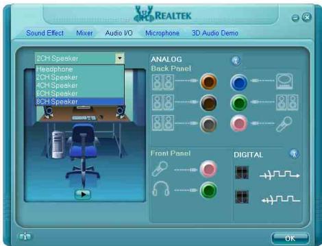
- After restarting the system, right-click the Sound Manager icon located at the desktop shortcut. Click item "Sound Manager". The Realtek HD Audio Manager appears.

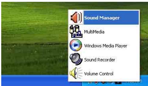
- Click the [Audio I/O] tab.
- Click the pull down menu to select the channel configuration.
- Click [OK] button to apply the Audio I/O settings and exit.
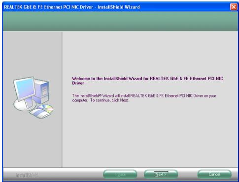
3.5 LAN Driver
To install this program:
- Click on the [Drivers] tab in the installation menu screen.
- Click the [LAN Driver] item. The installation screen appears.
- Follow the prompts on the screen to complete installation.
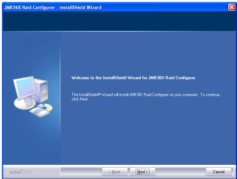
3.6 JMicron SATA Driver
This driver provides functionality for the onboard SATA RAID Controller.
This driver installation is necessary for the devices connected through connectors "eSATA1" or "IDE1".
To install this program:
- Click on the [Drivers] tab in the installation menu screen.
- Click the [JMicron SATA Driver] item. The installation screen appears.
- Follow the prompts on the screen to complete installation.
3.7 USB 2.0 Driver
There is no need to install this driver for Windows 2000 with Service Pack 4, Windows XP with Service Pack 1, or their later version.
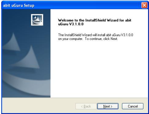
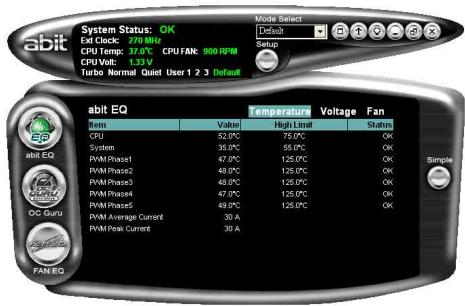
3.8 ABIT μGuru Utility
The μGuru Utility combined with the optional Guru Panel allows you to access and select system performance of your system while playing games, listening music, browsing Internet or office applications in full screen with no need to stop or close the running application.
To install this utility:
- Click on the [abit Utility] tab in the installation menu screen.
- Click the [abit uGuru] item. The following screen appears.

- Follow the prompts on the screen to complete installation.
- Restart the system for the program to take effect.
- Execute the abit EQ by entering the Windows Menu [Start] [All Programs] [abit] [abit uGuru].
- The μGuru Utility shows you the status of Voltage, Fan Speed, and Temperature readings as well.
3.9 Build Intel SATA RAID Driver Disk Under Windows Environment
This procedure is necessary if you want to install operating system to a RAID configuration connected among "SATA1~SATA6" connectors:
- Prepare a 3.5'' floppy disk drive and connect it to "FDC1" connector on this motherboard.
- Start install operating system.
- Insert this driver disk into floppy disk drive when the screen instruction prompts you to install a third-party SCSI or RAID driver.
- Press <F6> key, and then follow the screen instruction to complete the installation.
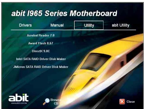
To create a driver disk:
- Click on the [Utility] tab in the installation menu screen.
- Click the [Intel SATA RAID Driver Disk Maker] item. The installation screen appears.
- Insert one blank floppy disk to the selected floppy drive and click [Build].
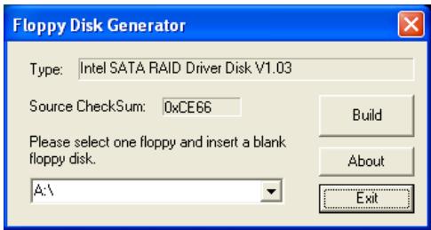
- Click [OK] to finish building the SATA Driver Disk.
- Click [Exit] to exit this utility.
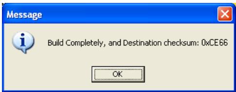
Build Completely, and Destination checksum: 0xCE66
3.10 Build JMicron SATA RAID Driver Disk Under Windows Environment
This procedure is necessary if there is access to the devices connected to connectors "eSATA1" during the OS installation:
- Prepare a 3.5'' floppy disk drive and connect it to "FDC1" connector on this motherboard.
- Start install operating system.
- Insert this driver disk into floppy disk drive when the screen instruction prompts you to install a third-party SCSI or RAID driver.
- Press <F6> key, and then follow the screen instruction to complete the installation.
This procedure is particularly necessary when you want to install operating system from a CD-ROM drive connected through connectors "eSATA1".
To create a driver disk:
- Click on the [Utility] tab in the installation menu screen.
- Click the [JMicron SATA RAID Driver Disk Maker] item. The installation screen appears.

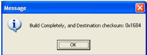
- Insert one blank floppy disk to the selected floppy drive and click [Build].
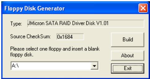
- Click [OK] to finish building the SATA Driver Disk.
- Click [Exit] to exit this utility.
3.11 Build A Driver Disk Under DOS Environment
The "Driver Disk Maker" program bundled in the Driver-&-Utility CD is a utility to build the driver program needed for SATA controller into a floppy disk under DOS environment. This procedure is necessary only for installing Windows operating system to the hard disk connected to "eSATA1" or "SATA1~SATA6" connector.
To create a driver disk:
- Before starting, connect a 3.5'' floppy disk drive to the "FDC1" connector, and connect a CD-ROM drive to your motherboard. Prepare a 3.5'' floppy disk.
- After completing all the start-up preparation for hardware setup, power on the system.
- Enter the BIOS Setup Menu by hitting <Del> key1.
Enter and select the BIOS menu "Advanced BIOS Features". Configure the option "First Boot Device" to "CD-ROM" drive. Save this selection and exit BIOS setup menu by accessing the BIOS menu "Save & Exit Setup".
- Restart the system. The system will now boot from CD, and enter the ABIT Boot Manager, the following options appear3:
(0) Boot From First HDD
(1) Make Driver Disk
(2) Boot From First Floppy Drive
(3) Skip CD-ROM Boot (Try Next Boot Device)
Type <1> and hit
(1) Make Driver Disk
(2) Exit
Type <1> and hit <Enter> key to start making.
- The driver options appear:
(1) Intel SATA RAID Driver Disk Maker
(2) JMicron SATA RAID Driver Disk Maker
Type the number of the actions you want and hit
- Insert floppy disk to the floppy drive4. Press any key to continue.
- Copying files to floppy now starts. After completed copying, hit the <n> key if you do not want to make another Driver Disk, and stop at the A:> prompt.
- Take out the Driver- &- Utility CD from the CD-ROM drive now. Restart your system ^5 .
4. Multilingual Quick Installation Guide
Interne Audioanschlüsse: [CD1], [AUX1]

- AB9 QuadGT
- Copyright and Warranty Notice
- Hardware Setup 1-1
- BIOS Setup 2-1
- Driver & Utility 3-1
- Multilingual Quick Installation Guide 4-1
- Hardware Setup
- Specifications
- CPU
- Chipset
- Memory
- LAN
- Audio
- Serial ATA
- IEEE1394
- Expansion Slots
- Internal I/O Connectors
- Rear Panel I/O
- abit Engineered
- RoHS
- Miscellaneous
- Choosing a Computer Chassis
- Installing Motherboard
- To install this motherboard:
- Checking Jumper Settings
- CMOS Memory Clearing Header and Backup Battery
- To clear the CMOS memory and load in the default values:
- CMOS Backup Battery:
- To renew the backup battery:
- CAUTION:
- Wake-up Header
- USB-PWR1:
- USB-PWR2:
- Connecting Chassis Components
- ATX Power Connectors
- ATXPWR1: ATX 24-Pin Power Connector
- ATX12V1: ATX 12V 8-Pin Power Connector
- ATX4P1: Auxiliary 12V Power Connector
- Front Panel Switches & Indicators Headers
- FAN Power Connectors
- abit Silent OTES™ Technology
- Installing Hardware
- CPU Socket 775
- DDR2 Memory Slots
- Usually there is no hardware or BIOS setup required after adding or removing memory modules, but you will have to clear the CMOS memory first if any memory module related problem occurs.
- To install system memory:
- PCI Express X16 Add-on Slots (Install Graphics Card)
- One PCIE graphics card installation (Normal Mode):
- Two PCIE graphics cards installation (CrossFire Mode):
- To enable CrossFire Mode, you will need to:
- Connecting Peripheral Devices
- Floppy and IDE Disk Drive Connectors
- The red line on the ribbon cable must be aligned with pin-1 on both the FDC1 port and the floppy connector.
- Serial ATA Connectors
- To connect SATA device:
- Additional USB 2.0 Port Headers
- Additional IEEE1394 Port Header
- Internal Audio Connectors
- Front Panel Audio Connection Header
- Driver Configuration for AC'97 audio connection:
- S/PDIF Output Connection Header
- PCI and PCI Express X1 Slot
- Guru Panel Connection Header
- Onboard Indicators and Buttons
- POST Code Displayer
- ※ The decimal point lights up during the AC2005 POST action.
- Power Source Indicators
- Onboard Buttons
- Connecting Rear Panel I/O Devices
- To clear the CMOS memory by EZ-CCMOS1:
- ※ The C.C. POST Code appears when either the external "EZ-CCMOS1" switch or the internal "CCMOS1" jumper is not set to its normal position.
- BIOS Setup
- PRESS DEL TO ENTER SETUP
- μGuru™ Utility
- OC Guru
- Genuine Intel(R) CPU
- Frequency
- CPU Operating Speed
- User Define:
- External Clock
- Voltages Control
- Power Cycle Statistics
- ABIT EQ
- ABIT EQ Beep Control
- LED Effect Control
- Temperature Monitoring
- CPU, System, PWM1~5 Temperature/PWM Current
- - Shutdown Enable
- - Shutdown Temp.
- - Beep Enable
- - Beep Temp.
- All Voltages
- High/Low Limit
- Fan Speed Monitoring
- CPU/SYS/AUX1~4 FAN Speed
- - Low Limit
- 1st FanEQ Group
- CPU/SYS/AUX1 FanEQ Control
- Reference Temperature
- AUX2\~AUX4 FanEQ Control
- Standard CMOS Features
- Date (mm:dd:yy)
- Time (hh:mm:ss)
- SATA Channel 1 ~ SATA Channel 6
- Base Memory
- Extended Memory
- Total Memory
- Advanced BIOS Features
- CPU L3 Cache
- CPU Feature
- Thermal Control
- Thermal Management
- Limit CPUID MaxVal
- C1E Function
- Execute Disable Bit
- Virtualization Technology
- EIST Function
- Back to Advanced BIOS Features Setup Menu
- Hard Disk Boot Priority
- Hyper-Threading Technology
- Quick Power On Self Test
- Advanced Chipset Features
- DRAM Timing Selectable
- PCI-E Compliancy Mode
- PEG Force X1
- Init Display First
- Integrated Peripherals
- OnChip IDE Device
- IDE Bus Master
- SATA Mode
- OnChip USB Controller
- USB 2.0 Controller
- USB Keyboard Support
- - USB Mouse Support
- OnChip Audio Controller
- Onboard 1394 Controller
- Onboard LAN Controller
- - Invoke Boot Agent
- JMB363 Controller
- - Controller Mode
- Back to Integrated Peripherals Setup Menu
- Onboard FDC Controller
- Power Management Setup
- ACPI Suspend Type
- Resume by USB from S3
- Power Button Function
- Wake Up by Wake# of PCIe
- Wake Up by PME# of PCI
- Wake Up by Onboard LAN
- Resume by Alarm
- - Date (of Month) Alarm
- Time (hh:mm:ss) Alarm
- POWER ON Function
- KB Power ON Password
- Hot Key Power ON
- Restore On AC Power Loss
- PnP/PCI Configurations
- Resources Controlled By
- - IRQ Resources
- PCI/VGA Palette Snoop
- Load Fail-Safe Defaults
- Load Optimized Defaults
- Set Password
- Save & Exit Setup
- Exit Without Saving
- Driver & Utility
- CD-ROM AUTORUN
- To run the CD-ROM automatically:
- Found New Hardware Wizard
- Welcome to the Found New Hardware Wizard
- Intel Chipset Software Installation Utility
- To install this program:
- Intel Matrix Storage Manager
- Audio Driver
- LAN Driver
- JMicron SATA Driver
- USB 2.0 Driver
- ABIT μGuru Utility
- To install this utility:
- Build Intel SATA RAID Driver Disk Under Windows Environment
- To create a driver disk:
- Build JMicron SATA RAID Driver Disk Under Windows Environment
- Build A Driver Disk Under DOS Environment
- Multilingual Quick Installation Guide
- Interne Audioanschlüsse: [CD1], [AUX1]
Brand : ABIT
Model : AB9 QUADGT
Category : Motherboard