AN-M2HD-LE - Motherboard ABIT - Free user manual and instructions
Find the device manual for free AN-M2HD-LE ABIT in PDF.

| Product Type | Motherboard |
| Brand | ABIT |
| Model | AN-M2HD-LE |
| Form Factor | Micro ATX |
| Dimensions (W x L) | 244 mm x 244 mm |
| Weight | Approx. 0.8 kg |
| CPU Socket | Socket AM2/AM2+ |
| Supported CPUs | AMD Athlon 64, Athlon 64 X2, Sempron |
| Chipset | NVIDIA GeForce 7050 + nForce 630a |
| Memory Slots | 2 x DDR2 DIMM, up to 8 GB |
| Expansion Slots | 1 x PCIe x16, 1 x PCIe x1, 2 x PCI |
| Storage Interfaces | 2 x SATA 3 Gb/s, 1 x IDE |
| USB Ports (Rear) | 4 x USB 2.0 |
| Audio | Realtek ALC662 6-channel HD Audio |
| LAN | Realtek RTL8102E 10/100 Mbps |
| Power Input | 24-pin ATX + 4-pin 12V |
| Onboard Video | Integrated NVIDIA GeForce 7050 |
| BIOS | AWARD BIOS, 8 Mbit Flash ROM |
| Operating Temperature | 0°C to 45°C (32°F to 113°F) |
| Maintenance | Keep clean with compressed air; avoid moisture |
| Safety | Disconnect power before installing; ESD precautions |
| Spare Parts & Repairability | Replace CMOS battery (CR2032); limited repairability |
| Included Accessories | I/O shield, SATA cables, driver CD, manual |
Frequently Asked Questions - AN-M2HD-LE ABIT
User questions about AN-M2HD-LE ABIT
0 question about this device. Answer the ones you know or ask your own.
Ask a new question about this device
Download the instructions for your Motherboard in PDF format for free! Find your manual AN-M2HD-LE - ABIT and take your electronic device back in hand. On this page are published all the documents necessary for the use of your device. AN-M2HD-LE by ABIT.
USER MANUAL AN-M2HD-LE ABIT
text_image
Mouse Keyboard OPT-OUT1 HDMI1 VGA1 AUDIO1 IEEE1394 USB1 LAN1 USB2 ATX12V1 SYSFAN1 CPUFAN1 AUXFAN1 SPDIFO1 LAN Controller PCIEXP1 PCIE1 FP-AUDIO1 FP-1394-1 PCI1 PCI2 CCMOS1 a bit AN-M2HD BIOS Super I/O BAT1 CR2032 3V+ 5VSB SATA3 SATA4 SATA1 SATA2 FP-USB1 FP-USB2 FP-USB3 FP-USB4AN-M2
AN-M2HD
Motherboard
AMD Socket AM2
User's Manual
☐ GeForce 7025/nForce 630a (AN-M2)
GeForce 7050PV/nForce 630a (AN-M2HD)
2000MT/s HT
Dual Channel DDR2 800
NVIDIA PureVideo™
NVIDIA nView™
☐ HDMI (AN-M2HD) / DVI (AN-M2)
□ Gigabit LAN
☐ SATA 3Gb/s RAID
☐ USB 2.0 / IEEE1394 (AN-M2HD)
7.1-Channel HD Audio
□ abit SoftMenu™ Technology
□ Vista HW Ready
AN-M2/AN-M2HD
User's Manual
English + Multilingual QIG
P/N: 4310-0000-84
Rev. 3.00, April 2007
Copyright and Warranty Notice
The information in this document is subject to change without notice and does not represent a commitment on part of the vendor, who assumes no liability or responsibility for any errors that may appear in this manual.
No warranty or representation, either expressed or implied, is made with respect to the quality, accuracy or fitness for any particular part of this document. In no event shall the manufacturer be liable for direct, indirect, special, incidental or consequential damages arising from any defect or error in this manual or product.
Product names appearing in this manual are for identification purpose only and trademarks and product names or brand names appearing in this document are the property of their respective owners.
This document contains materials protected under International Copyright Laws. All rights reserved. No part of this manual may be reproduced, transmitted or transcribed without the expressed written permission of the manufacturer and authors of this manual.
If you do not properly set the motherboard settings, causing the motherboard to malfunction or fail, we cannot guarantee any responsibility.
The Following Information is Only for EU-member States:

Directive 2002/96/EC on Waste Electrical and Electronic Equipment (WEEE): The use of the symbol indicates that this product may not be treated as household waste. By Ensuring this product is disposed of correctly, you will help prevent potential negative consequences for the environment and human health, which could otherwise be cause by inappropriate waste handling of this product. For more detailed information about recycling of this product, please contact your local city office, your household waste disposal service or the shop where you purchased the product.
1. Hardware Setup 1-1
1.1 Specifications.... 1-1
1.1.1 AN-M2 1-1
1.1.2 AN-M2HD....1-2
1.2 Motherboard Layout 1-3
1.2.1 AN-M2 1-3
1.2.2 AN-M2HD.... 1-4
1.3 Choosing a Computer Chassis 1-5
1.4 Installing Motherboard 1-5
1.5 Checking Jumper Settings.... 1-6
1.5.1 CMOS Memory Clearing Header and Backup Battery 1-6
1.6 Connecting Chassis Components.... 1-8
1.6.1 Power Connectors 1-8
1.6.2 Front Panel Switches & Indicators Headers 1-9
1.6.3 FAN Power Connectors 1-9
1.7 Installing Hardware 1-10
1.7.1 CPU Socket AM2.... 1-10
1.7.2 DDR2 Memory Slots.... 1-12
1.8 Connecting Peripheral Devices 1-13
1.8.1 Floppy and IDE Disk Drive Connectors 1-13
1.8.2 Serial ATA Connectors 1-14
1.8.3 Additional USB 2.0 Port Headers.... 1-15
1.8.4 Additional IEEE1394 Port Header 1-15
1.8.5 Internal Audio Connectors.... 1-16
1.8.6 Front Panel Audio Connection Header 1-16
1.8.7 S/PDIF Output Connection Header 1-18
1.8.8 PCI and PCI Express X16, X1 Slots 1-18
1.9 Onboard Indicators 1-19
1.9.1 Power Source Indicators 1-19
1.10 Connecting Rear Panel I/O Devices 1-20
2. BIOS Setup.... 2-1
2.1 SoftMenu Setup 2-2
2.2 Standard CMOS Features 2-4
2.3 Advanced BIOS Features 2-7
2.4 Advanced Chipset Features.... 2-9
2.5 Integrated Peripherals.... 2-10
2.6 Power Management Setup 2-13
2.7 PnP/PCI Configurations 2-15
2.8 PC Health Status 2-16
2.9 Load Fail-Safe Defaults.... 2-18
2.10 Load Optimized Defaults.... 2-18
2.11 Set Password 2-18
2.12 Save & Exit Setup.... 2-18
2.13 Exit Without Saving 2-18
3. Driver & Utility 3-1
3.1 CD-ROM AUTORUN 3-1
3.2 nVidia nForce Chipset Driver 3-2
3.3 Realtek HD Audio Driver 3-2
3.4 Cool'n'Quiet Driver 3-4
3.5 USB 2.0 Driver 3-4
3.6 abitEQ (The Hardware Doctor Utility) 3-5
3.7 FlashMenu (BIOS Update Utility) 3-6
3.8 SATA RAID Driver (for Windows Vista) 3-7
3.9 SATA RAID Driver (for Windows XP, 2003, or 2000)......3-7
4. Multilingual Quick Installation Guide 4-1
5.1 Troubleshooting (How to Get Technical Support?)...... 5-1
5.1.1 Q & A 5-1
5.1.2 Technical Support Form.... 5-4
5.1.3 Contact Information.... 5-5
1. Hardware Setup
1.1 Specifications
1.1.1 AN-M2
CPU
- Supports Socket AM2 940 Processor with 2000MT/s system bus using Hyper Transport™ Technology
- Supports AMD CPU Cool 'n' Quiet Technology
Chipset
• NVIDIA GeForce 7025 / nForce 630a
Memory
- 4x 240-pin DIMM slots support maximum memory capacity up to 8GB
• Supports Dual Channel DDR2 800 Un-buffered ECC/Non-ECC memory
Graphics
- Integrated GeForce7 Series Graphics
- Support DirectX 9.0, Shader Model 3.0, nView
- Programmable PureVideo HD Video Processor
LAN
- Onboard Gigabit LAN
Audio
- Onboard 7.1-CH HD Audio CODEC
• Supports auto jack sensing and S/PDIF Out
Serial ATA
- 4x SATA 3Gb/s supports SATA RAID 0, 1, 0+1, 5, and JBOD
Expansion Slots
- 1x PCI-E X16 slot
- 1x PCI-E X1 slot
- 2x PCI slots
Internal I/O Connectors
- 1x Floppy port
• 1x Ultra ATA 133 IDE connector
• 4x SATA 3Gb/s connectors - 3x USB 2.0 headers
- 1x FP-Audio header
- 1x CD-In connector
Rear Panel I/O
• 1x PS/2 Keyboard connector
• 1x PS/2 Mouse connector
• 1x Optical S/PDIF Out connector
- 1x D-Sub connector
- 1x DVI connector
• 1x 7.1-CH Audio connector
- 4x USB 2.0 connectors
• 1x RJ-45 Gigabit LAN connector
abit Engineered
- abit Softmenu™ Technology
RoHS
- 100% Lead-free process and RoHS compliant
Miscellaneous
- Micro ATX form factor (244mm x 244mm)
- Vista HW Ready
※ Specifications and information contained herein are subject to change without notice.
1.1.2 AN-M2HD
CPU
- Supports Socket AM2 940 Processor with 2000MT/s system bus using Hyper Transport™ Technology
- Supports AMD CPU Cool 'n' Quiet Technology
Chipset
• NVIDIA GeForce 7050PV / nForce 630a
Memory
- 4x 240-pin DIMM slots support maximum memory capacity up to 8GB
• Supports Dual Channel DDR2 800 Un-buffered ECC/Non-ECC memory
Graphics
- Integrated GeForce7 Series Graphics
- Support DirectX 9.0, Shader Model 3.0, nView
- Programmable PureVideo HD Video Processor
HDMI
- Onboard HDMI connector support audio/video output
LAN
- Onboard Gigabit LAN
Audio
- Onboard 7.1-CH HD Audio CODEC
• Supports auto jack sensing and S/PDIF Out
Serial ATA
- 4x SATA 3Gb/s supports SATA RAID 0, 1, 0+1, 5, and JBOD
Expansion Slots
- 1x PCI-E X16 slot
- 1x PCI-E X1 slot
- 2x PCI slots
Internal I/O Connectors
- 1x Floppy port
• 1x Ultra ATA 133 IDE connector
• 4x SATA 3Gb/s connectors - 4x USB 2.0 headers
• 1x IEEE1394 header - 1x FP-Audio header
- 1x CD-In connector
- 1x S/PDIF Out header
Rear Panel I/O
• 1x PS/2 Keyboard connector
• 1x PS/2 Mouse connector
• 1x Optical S/PDIF Out connector
- 1x HDMI connector
- 1x D-Sub connector
• 1x 7.1-CH Audio connector
• 1x IEEE1394 connector
- 4x USB 2.0 connectors
• 1x RJ-45 Gigabit LAN connector
abit Engineered
- abit Softmenu™ Technology
RoHS
- 100% Lead-free process and RoHS compliant
Miscellaneous
- Micro ATX form factor (244mm x 244mm)
- Vista HW Ready
※ Specifications and information contained herein are subject to change without notice.
1.2 Motherboard Layout
1.2.1 AN-M2
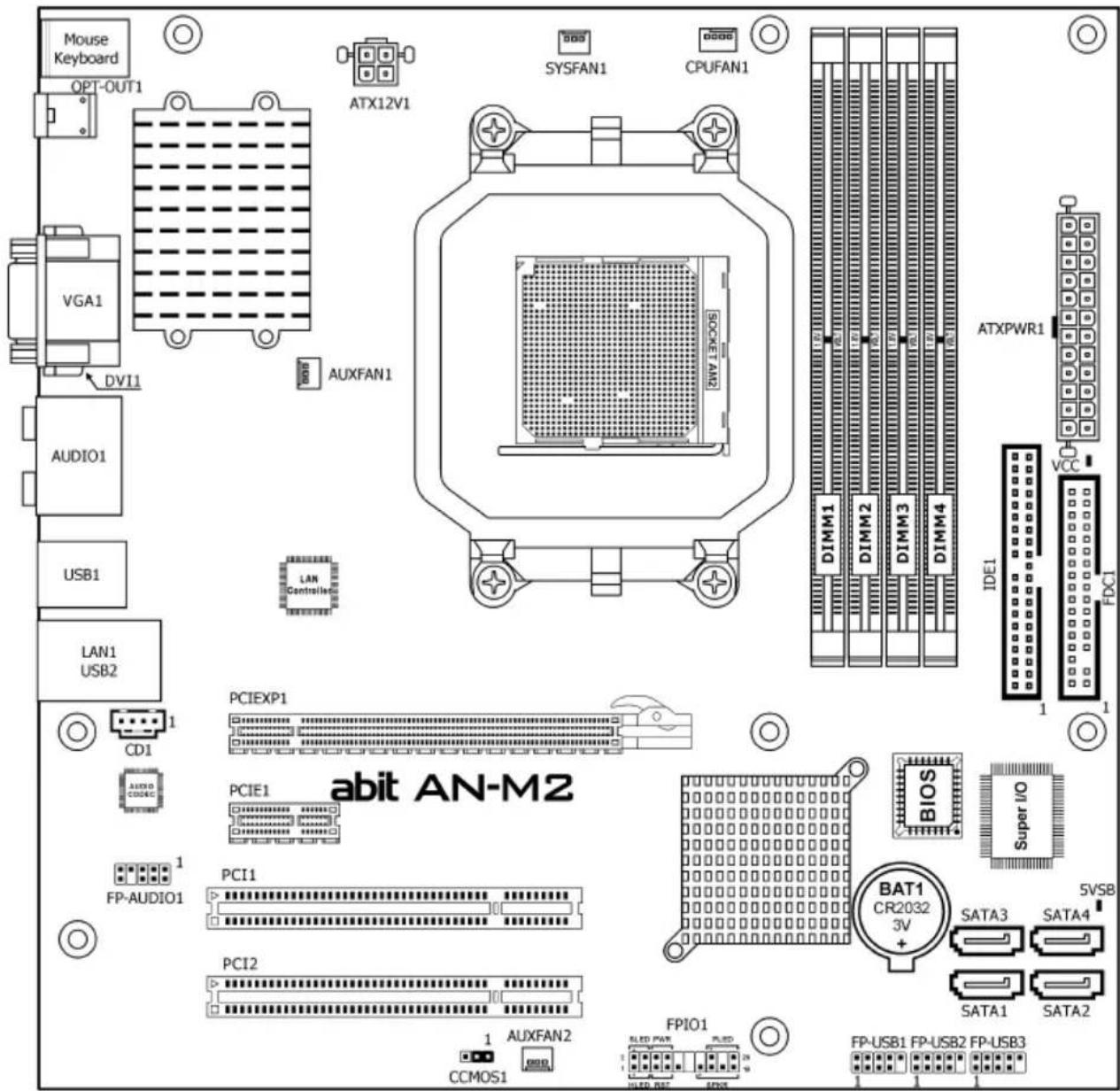
text_image
Mouse Keyboard OPT-OUT1 VGA1 DVI1 AUDIO1 USB1 LAN1 USB2 ATX12V1 SYSFAN1 CPUFAN1 AUXFAN1 LAN Controller PCIEXP1 PCIE1 PCI1 PCI2 CCI MOS1 1 AUXFAN2 FP-AUDIO1 PCI01 PCI2 1 AUXFAN2 FPIO1 5LED PWR SLED 24 UHLD BCC FPIO1 FP-USB1 FP-USB2 FP-USB3 BIT1 CR2032 3V BAT1 Super I/O BIOS Super I/O IDE1 VCC ATXPWR1 DIMM1 DIMM2 DIMM3 DIMM4 abit AN-M2 5VSB SATA3 SATA4 SATA1 SATA21.2.2 AN-M2HD
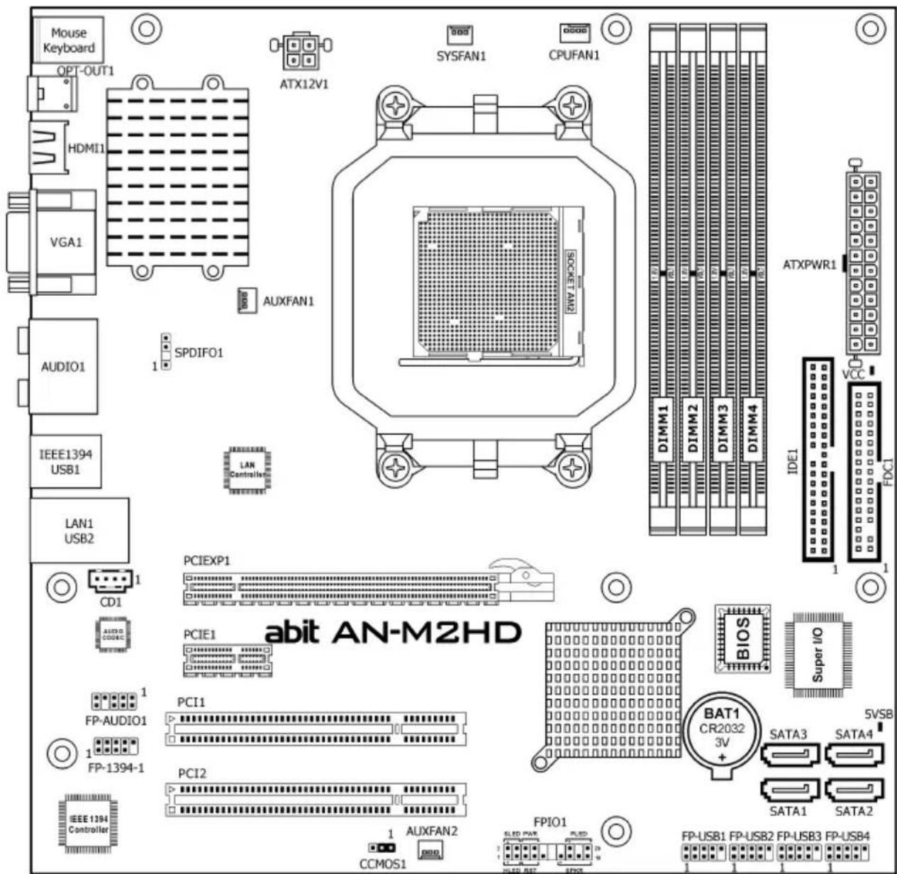
text_image
Mouse Keyboard OPT-OUT1 HDMI1 VGA1 AUDIO1 IEEE1394 USB1 LAN1 USB2 ATX12V1 SYSFAN1 CPUFAN1 AUXFAN1 SPDIFO1 LAN Controller PCIEXP1 PCIE1 PCI1 PCI2 CCIOS1 AFFAN2 FPIO1 SLED PWR PLED HLED BIT FP00 ATXPWR1 DIMM1 DIMM2 DIMM3 DIMM4 IDE1 VCC FXC1 BITAN-M2HD BIOS Super I/O BAT1 CR2032 3V+ 5VSB SATA3 SATA4 SATA1 SATA2 FP-AUDIO1 FP-1394-1 IEEE 1394 Controller※ The motherboard and its component layouts illustrated in the following chapter of this manual were mainly based on model "AN-M2HD", unless specifically stated.
1.3 Choosing a Computer Chassis
- Choose a chassis big enough to install this motherboard.
- As some features for this motherboard are implemented by cabling connectors on the motherboard to indicators and switches or buttons on the chassis, make sure your chassis supports all the features required.
- If there is a possibility of adopting some more hard drives, make sure your sufficient power and space for them.
- Most chassis have alternatives for I/O shield located at the rear panel. Make sure the I/O shield of the chassis matches the I/O port configuration of this motherboard. You can find an I/O shield specifically designed for this motherboard in its package.
1.4 Installing Motherboard
Most computer chassis have a base with many mounting holes to allow the motherboard to be securely attached, and at the same time, prevent the system from short circuits. There are two ways to attach the motherboard to the chassis base: (1) with studs, or (2) with spacers.
Basically, the best way to attach the board is with studs. Only if you are unable to do this should you attach the board with spacers. Line up the holes on the board with the mounting holes on the chassis. If the holes line up and there are screw holes, you can attach the board with studs. If the holes line up and there are only slots, you can only attach with spacers. Take the tip of the spacers and insert them into the slots. After doing this to all the slots, you can slide the board into position aligned with slots. After the board has been positioned, check to make sure everything is OK before putting the chassis back on.

text_image
STUD SPACER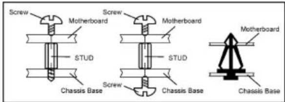
text_image
Screw Motherboard STUD Screw Motherboard STUD Screw Chassis Base Chassis Base Motherboard Chassis Base※ Always power off the computer and unplug the AC power cord before adding or removing any peripheral or component. Failing to so may cause severe damage to your motherboard and/or peripherals. Plug in the AC power cord only after you have carefully checked everything.
To install this motherboard:
- Locate all the screw holes on the motherboard and the chassis base.
- Place all the studs or spacers needed on the chassis base and have them tightened.
- Face the motherboard's I/O ports toward the chassis's rear panel.
- Line up all the motherboard's screw holes with those studs or spacers on the chassis.
- Install the motherboard with screws and have them tightened.
※ To prevent shorting the PCB circuit, please REMOVE the metal studs or spacers if they are already fastened on the chassis base and are without mounting-holes on the motherboard to align with.
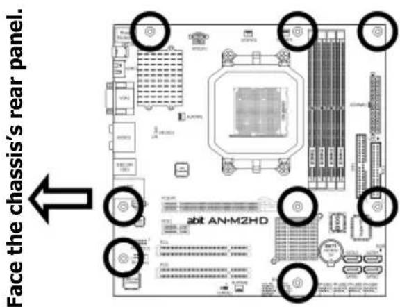
text_image
Face the chassis's rear panel. abit AN-M2HD1.5 Checking Jumper Settings
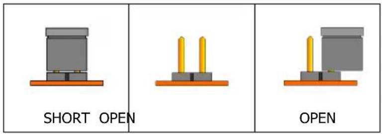
- For a 2-pin jumper, plug the jumper cap on both pins will make it CLOSE (SHORT). Remove the jumper cap, or plug it on either pin (reserved for future use) will leave it at OPEN position.
text_image
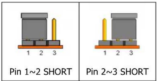
SHORT OPEN OPEN- For 3-pin jumper, pin 1\~2 or pin 2\~3 can be shorted by plugging the jumper cap in.
text_image
Pin 1~2 SHORT Pin 2~3 SHORT1.5.1 CMOS Memory Clearing Header and Backup Battery
The time to clear the CMOS memory occurs when (a) the CMOS data becomes corrupted, (b) you forgot the supervisor or user password preset in the BIOS menu, (c) you are unable to boot-up the system because the CPU ratio/clock was incorrectly set in the BIOS menu, or (d) whenever there is modification on the CPU or memory modules.
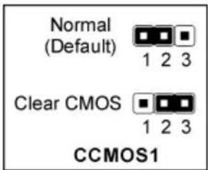
This header uses a jumper cap to clear the CMOS memory and have it reconfigured to the default values stored in BIOS.
- Pins 1 and 2 shorted (Default): Normal operation.
- Pins 2 and 3 shorted: Clear CMOS memory.
text_image
Normal (Default) 1 2 3 Clear CMOS 1 2 3 CCMOS1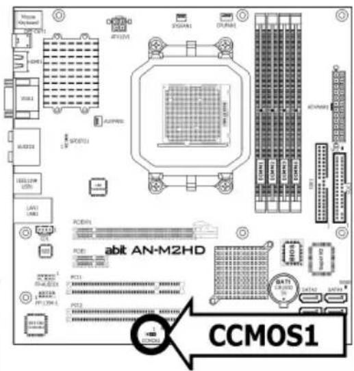
text_image
CCMOS1 abit AN-M2HDTo clear the CMOS memory and load in the default values:
- Power off the system.
- Set pin 2 and pin 3 shorted by the jumper cap. Wait for a few seconds. Set the jumper cap back to its default settings --- pin 1 and pin 2 shorted.
- Power on the system.
- For incorrect CPU ratio/clock settings in the BIOS, press
key to enter the BIOS setup menu right after powering on system. - Set the CPU operating speed back to its default or an appropriate value.
- Save and exit the BIOS setup menu.
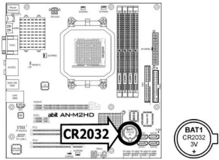
CMOS Backup Battery:
An onboard battery saves the CMOS memory to keep the BIOS information stays on even after disconnected your system with power source. Nevertheless, this backup battery exhausts after some five years. Once the error message like "CMOS BATTERY HAS FAILED" or "CMOS checksum error" displays on monitor, this backup battery is no longer functional and has to be renewed.
text_image
Motor Keyboard ACR2031 ACR1 YAGL ALOEL ECB1284 USB1 LAME GND2 PCB1 PCB2 PCB3 PCB4 PCB5 PCB6 PCB7 PCB8 PCB9 PCB10 PCB11 PCB12 PCB13 PCB14 PCB15 PCB16 PCB17 PCB18 PCB19 PCB20 PCB21 PCB22 PCB23 PCB24 PCB25 PCB26 PCB27 PCB28 PCB29 PCB30 PCB31 PCB32 PCB33 PCB34 PCB35 PCB36 PCB37 PCB38 PCB39 PCB40 PCB41 PCB42 PCB43 PCB44 PCB45 PCB46 PCB47 PCB48 PCB49 PCB50 PCB51 PCB52 PCB53 PCB54 PCB55 PCB56 PCB57 PCB58 PCB59 PCB60 PCB61 PCB62 PCB63 PCB64 PCB65 PCB66 PCB67 PCB68 PCB69 PCB70 PCB71 PCB72 PCB73 PCB74 PCB75 PCB76 PCB77 PCB78 PCB79 PCB80 PCB81 PCB82 PCB83 PCB84 PCB85 PCB86 PCB87 PCB88 PCB89 PCB90 PCB91 PCB92 PCB93 PCB94 PCB95 PCB96 PCB97 PCB98 PCB99 PCB100 DC100A DC100D DC100E DC100F DC100G DC100H DC100I DC100J DC100K DC100L DC100M DC100N DC100O DC100P DC100Q DC100R DC100S DC100T DC100U DC100V DC100W DC100X DC100Y DC100Z DC100A DC100V DC100W DC100X DC100Y DC100Z DC100A DC100V DC100W DC100X DC100Y DC100Z DC100A DC100V DC100W DC100X DC100Y DC100Z DC100A DC100V DC100 W DC100A DC100V DC100W DC100X DC100Y DC100Z DC100A DC100V DC100W DC100X DC100Y DC100Z DC100A DC100V DC100W DC100X DC100Y DC100Z DC100A DC100 V DC100A DC100V DC100W DC100X DC100Y DC100Z DC100A DC100V DC100W DC100X DC100Y DC100Z DC100A DC100V DC100W DC100X DC100Y DC100Z DC100A DC100A DC102A DC22A DC22A AC22A AC22A AC22A AC22A AC22A AC22A AC22A AC22A AC22A AC22A AC22A AC22A AC22A AC22A AC22A AC22A AC22A AC22A AC22A AC22A AC22A AC22A AC22A AC22A AC22A ABIT AN-M2HD CR2O32 BAT1 CR2O32 3V +To renew the backup battery:
- Power off the system and disconnect with AC power source.
- Remove the exhausted battery.
- Insert a new CR2032 or equivalent battery. Pay attention to its polarity. The "+" side is its positive polarity.
- Connect AC power source and power on the system.
- Enter the BIOS setup menu. Reconfigure the setup parameters if necessary.
CAUTION:
※ Danger of explosion may arise if the battery is incorrectly renewed.
※ Renew only with the same or equivalent type recommended by the battery manufacturer.
※ Dispose of used batteries according to the battery manufacturer's instructions.
1.6 Connecting Chassis Components
1.6.1 Power Connectors
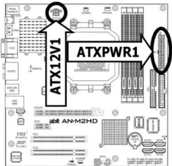
These connectors provide the connection from an ATX power supply. As the plugs from the power supply fit in only one orientation, find the correct one and push firmly down into these connectors.
text_image
ATX12V1 ATXPWR1 abit AN-M2HDATXPWR1: ATX 24-Pin Power Connector
The power supply with 20-pin or 24-pin cables can both be connected to this 24-pin connector. Connect from pin-1 for either type. However, a 20-pin power supply may cause the system unstable or even unbootable for the sake of insufficient electricity. A minimum power of 300W or higher is recommended.
ATX12V1: ATX 12V 4-Pin Power Connector
This connector supplies power to CPU. The system will not start without connecting power to this one.
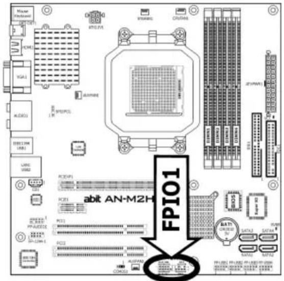
1.6.2 Front Panel Switches & Indicators Headers
This header is used for connecting switches and LED indicators on the chassis front panel.
Watch the power LED pin position and orientation. The mark "+" align to the pin in the figure below stands for positive polarity for the LED connection. Please pay attention when connecting these headers. A wrong orientation will only result in the LED not lighting, but a wrong connection of the switches could cause system malfunction.
• HLED (Pin 1, 3):
Connects to the HDD LED cable of chassis front panel.
- RST (Pin 5, 7):
Connects to the Reset Switch cable of chassis front panel.
• SPKR (Pin 13, 15, 17, 19):
Connects to the System Speaker cable of chassis.
- SLED (Pin 2, 4):
Connects to the Suspend LED cable (if there is one) of chassis front panel.
- PWR (Pin 6, 8):
Connects to the Power Switch cable of chassis front panel.
- PLED (Pin 16, 18, 20):
Connects to the Power LED cable of chassis front panel.
text_image
Maser HYPER AC/AC VGA1 AUDIO1 EBIT 274K USB1 LANC USB2 PC30P1 PC31 PC32 PC33 PC34 PC35 PC36 PC37 PC38 PC39 PC40 PC41 PC42 PC43 PC44 PC45 PC46 PC47 PC48 PC49 PC50 PC51 PC52 PC53 PC54 PC55 PC56 PC57 PC58 PC59 PC60 PC61 PC62 PC63 PC64 PC65 PC66 PC67 PC68 PC69 PC70 PC71 PC72 FPI01 abit AN-M2H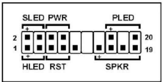
text_image
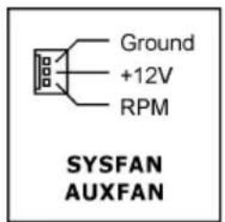
SLED PWR 2 1 HLED RST SPKR 20 191.6.3 FAN Power Connectors
These connectors each provide power to the cooling fans installed in your system.
• CPUFAN1: CPU Fan Power Connector
• SYSFAN1: System Fan Power Connector
- AUXFAN1\~2: Auxiliary Fan Power Connector
text_image
Ground +12V RPM SYSFAN AUXFAN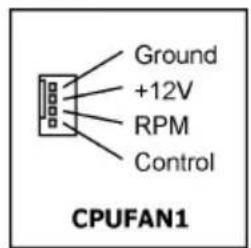
text_image
Ground +12V RPM Control CPUFAN1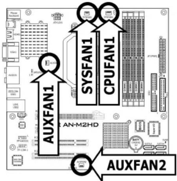
text_image
FXPEE KEYBOARD HDMI VGA1 AUTO CX IEEE CAN USB1 LAM USB2 AXLFAN1 SYSFAN1 CPUFAN1 AN-M2HD AXLFAN2※ These fan connectors are not jumpers. DO NOT place jumper caps on these connectors.
1.7 Installing Hardware
※ DO NOT scratch the motherboard when installing hardware. An accidentally scratch of a tiny surface-mount component may seriously damage the motherboard.
1.7.1 CPU Socket AM2
※ DO NOT touch or bend the delicate pins on the CPU whenever you are holding it.
The installation procedures vary with different types of CPU fan-and-heatsink assembly. The one shown here is served for DEMO only. For detailed information on how to install the one you bought, refer to its installation guidelines.
- Pull out the socket lever away from the socket and fully lift it up over 90-degree angle.
Locate and align the triangle mark with both the CPU and the socket body. Vertically place the CPU with its pin-side down into the socket.
Be careful to insert the CPU into the socket. The CPU only fits in one orientation with the socket. DO NOT force the CPU into the socket.
-
After placing the CPU into position, push the socket lever down into its locked position to secure the CPU. The lever clicks when it's locked into position.
-
The heatsink for CPU may have thermal interface material attached to its bottom. If not, applying a few squeeze of thermal paste to the CPU die will help to increase the contact.
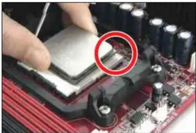
natural_image
Close-up of hands installing a CPU on a motherboard with a red circle highlighting the chip area (no text or symbols visible)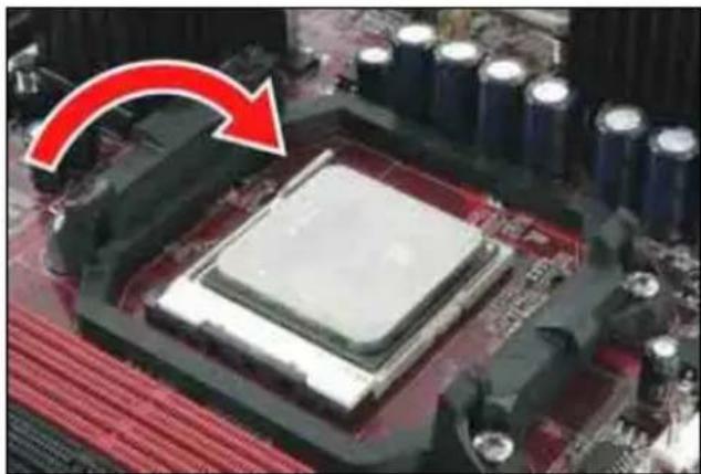
natural_image
Close-up of a computer motherboard with a highlighted CPU socket and red arrow indicating compression (no text or symbols)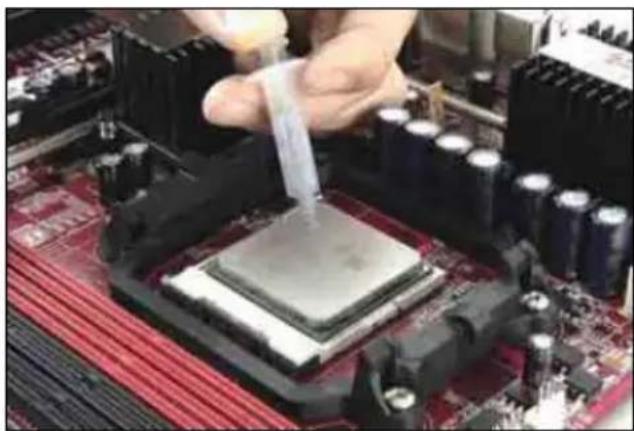
natural_image
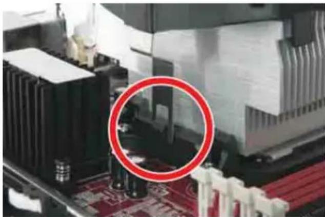
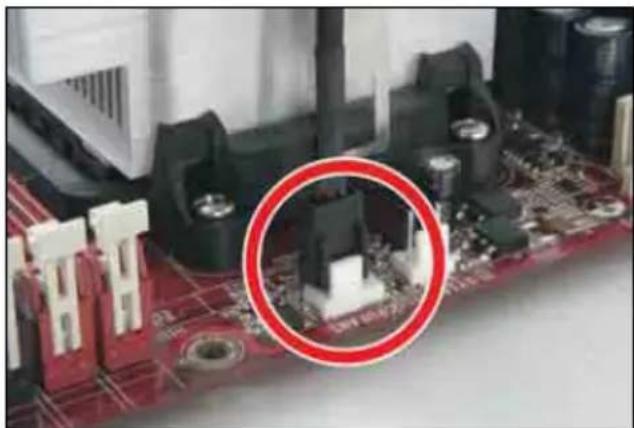
Close-up of a hand pouring liquid into a CPU socket on a motherboard (no visible text or symbols)- Place the heatsink and fan assembly onto the retention frame. Match the heatsink clip with the socket mounting-lug. Hook the spring clip to the mounting-lug.
natural_image
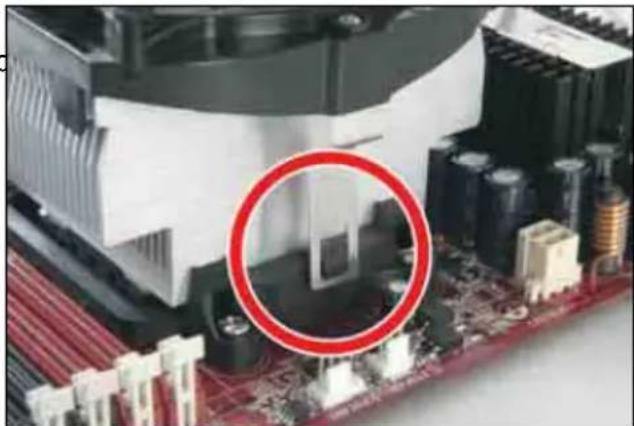
Close-up of a computer motherboard with visible CPU cooling units and a red circle highlighting a specific area (no text or symbols)- On the other side, push the retention clip straight down to lock into the plastic lug on the retention frame.
natural_image
Close-up of a computer motherboard with CPU socket and cooling unit highlighted by a red circle (no text or symbols)- Connect the CPU cooling fan power cable to the CPUFAN1 connector on this motherboard.
※ The "CPUFAN1" connector can be connected either with a 3-Pin or 4-Pin CPU cooling fan. For a 3-Pin connection, there will be no speed control available in the BIOS setup menu; the CPU fan will run at full speed.
natural_image
Close-up of a computer motherboard with visible components and a red circle highlighting a specific electronic component (no text or symbols present)Also, please watch out for the orientation when inserting 3-Pin plug into this 4-Pin fan connector.
※ The motherboard in this illustration is served for DEMO only, may not be the same type or model as the one described in this user's manual.
※ A higher fan speed will be helpful for better airflow and heat-dissipation. Nevertheless, stay alert to not touch any heatsink since a high temperature generated by the working system is still possible.
1.7.2 DDR2 Memory Slots
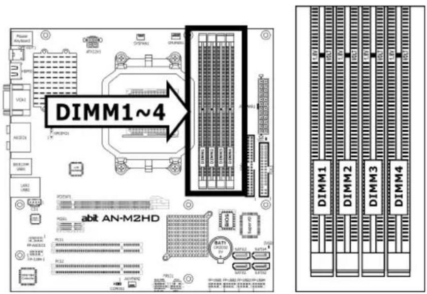
text_image
DIMM1~4 abit AN-M2HD DIMM1 DIMM2 DIMM3 DIMM4To reach the performance of Dual Channel DDR2, the following rules must be obeyed:
- For a 2-DIMM dual-channel installation:
Populate DIMM modules of the same type and size on slots [DIMM1]+[DIMM2], or slots [DIMM3]+[DIMM4].
- For a 4-DIMM dual-channel installation:
Populate 2 DIMM modules of the same type and size on slots [DIMM1]+[DIMM2], and another 2 DIMM modules of the same type and size on slots [DIMM3]+[DIMM4].
※ [DIMM1] and [DIMM2] slots are made of the same color. [DIMM3] and [DIMM4] are made of another same color.
Usually there is no hardware or BIOS setup requires after adding or removing memory modules, but you will have to clear the CMOS memory first if any memory module related problem occurs.
To install system memory:
- Power off the computer and unplug the AC power cord before installing or removing memory modules.
- Locate the DIMM slot on the board.
- Hold two edges of the DIMM module carefully, keep away from touching its connectors.
- Align the notch key on the module with the rib on the slot.
- Firmly press the module into the slots until the ejector tabs at both sides of the slot automatically snap into the mounting notch. Do not force the DIMM module in with extra force as the DIMM module only fits in one direction.
- To remove the DIMM modules, push the two ejector tabs on the slot outward simultaneously, and then pull out the DIMM module.
Static electricity can damage the electronic components of the computer or optional boards. Before starting these procedures, ensure that you are discharged of static electricity by touching a grounded metal object briefly.
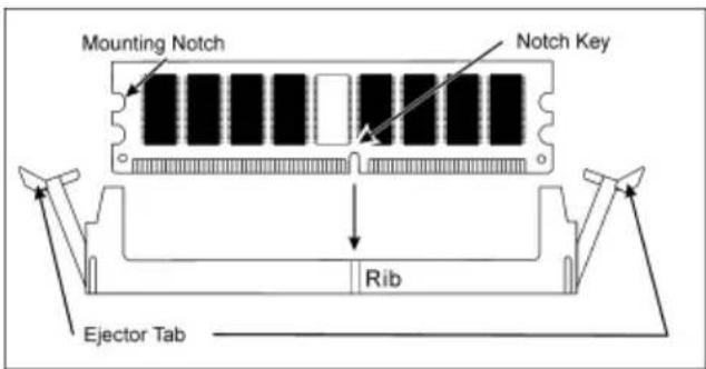
text_image
Mounting Notch Notch Key Rib Ejector Tab1.8 Connecting Peripheral Devices
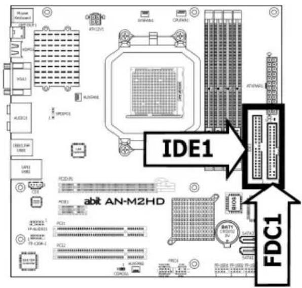
1.8.1 Floppy and IDE Disk Drive Connectors
text_image
Msquare Standard HSPD1 HYDCL HYDCL HYDCL HYDCL HYDCL HYDCL HYDCL HYDCL HYDCL HYDCL HYDCL HYDCL HYDCL HYDCL HYDCL HYDCL HYDCL HYDCL HYDCL HYDCL HYDCL HYDCL HYDCL HYDCL HYDCL HYDCl HYDCL HYDCL HYDCL HYDCL HYDCL HYDCL HYDCL HYDCL HYDCL HYDCL HYDCL HYDCL HYDCL HYDCL HYDCL HYDCL HYDCL HYDCL HYDCL HYDCL HYDCL HYDCL HYDCL HYDCL HYDGL HYDGL HYDGL HYDGL HYDGL HYDGL HYDGL HYDGL HYDGL HYDGL HYDGL HYDGL HYDGL HYDGL HYDGL HYDGL HYDGL HYDGL HYDGL HYDGL HYDGL HYDGL HYDGL HYDGL HYDGL HYD GLA10000000000000000000000000000000000000000000000000000000000000000000000000000000000000000000000000000 FDC1 FDC1 FDC1 FDC1 FDC1 FDC1 FDC1 FDC1 FDC1 FDC1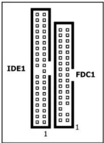
text_image
IDE1 FDC1 1 1The FDC1 connector connects up to two floppy drives with a 34-wire, 2-connector floppy cable. Connect the single end at the longer length of ribbon cable to the FDC1 on the board, the two connectors on the other end to the floppy disk drives connector. Generally you need only one floppy disk drive in your system.
※ The red line on the ribbon cable must be aligned with pin-1 on both the FDC1 port and the floppy connector.
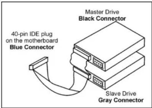
Each of the IDE port connects up to two IDE drives at Ultra ATA/100 mode by one 40-pin, 80-conductor, and 3-connector Ultra ATA/66 ribbon cables.
Connect the single end (blue connector) at the longer length of ribbon cable to the IDE port of this board, the other two ends (gray and black connector) at the shorter length of the ribbon cable to the connectors of your hard drives.
text_image
Master Drive Black Connector 40-pin IDE plug on the motherboard Blue Connector Slave Drive Gray Connector※ Make sure to configure the "Master" and "Slave" relation before connecting two drives by one single ribbon cable. The red line on the ribbon cable must be aligned with pin-1 on both the IDE port and the hard-drive connector.
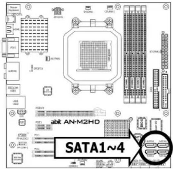
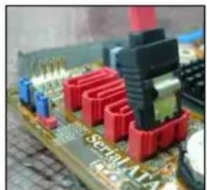
1.8.2 Serial ATA Connectors
Each SATA connector serves as one single channel to connect one SATA device by SATA cable.
text_image
SATA1~4 abit AN-M2HD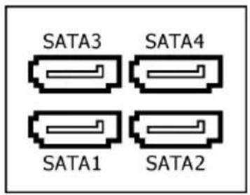
text_image
SATA3 SATA4 SATA1 SATA2To connect SATA device:
- Attach either end of the signal cable to the SATA connector on motherboard. Attach the other end to the SATA device.
- Attach the SATA power cable to the SATA device and connect the other end from the power supply.
natural_image
Close-up of a computer motherboard with red and black electronic components (no visible text or symbols)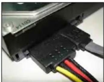
natural_image
Close-up of a black electronic component with red, yellow, and black wires connected to a white surface (no visible text or symbols)※ The motherboard in this photo is served for DEMO only, and may not be the same type or model as the one described in this user's manual.
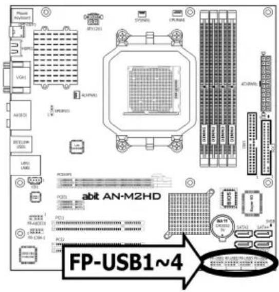
1.8.3 Additional USB 2.0 Port Headers
Each header supports 2x additional USB 2.0 ports by connecting bracket or cable to the rear I/O panel or the front-mounted USB ports of your chassis.
※ The header "FP-USB4" is available for model "AN-M2HD" only.
text_image
PPM N=6007 VGA1 AVCD1 RESET2W USB1 LINE1 PC3001 PCD3 PCD2 PCD1 R1-R2R3 R2-R3R4 R3-R4R5 R4-R5R6 R5-R6R7 R6-R7R8 R7-R8R9 R8-R9R10 R9-R10R11 R10-R11R12 R11-R12R13 R12-R13R14 R13-R14R15 R14-R15R16 R15-R16R17 R16-R17R18 R17-R18R19 R18-R19R20 R19-R20R21 R20-R21R22 R21-R22R23 R22-R23R24 R23-R24R25 R24-R25R26 R25-R26R27 R26-R27R28 R27-R28R29 R28-R29R30 R29-R30R31 R30-R31R32 R31-R32R33 R32-R33R34 R33-R34R35 R34-R35R36 R35-R36R37 R36-R37R38 R37-R38R39 R38-R39R40 RP-USB1~4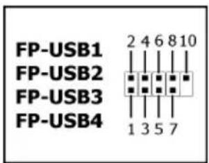
text_image
FP-USB1 2 4 6 8 10 FP-USB2 FP-USB3 FP-USB4 1 3 5 7| Pin Pin Assignment Pin Pin Assignment | |||
| 1 | VCC | 2 | VCC |
| 3 Data0 - 4 Data1 - | |||
| 5 | Data0 | + | 6 Data1 |
| 7 | Ground | 8 | Ground |
| 10 | NC | ||
※ Make sure the connecting cable bears the same pin assignment.
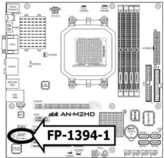
1.8.4 Additional IEEE1394 Port Header
Each header supports 1x additional IEEE1394 port by connecting bracket or cable to the rear I/O panel or the front-mounted IEEE1394 port of your chassis. (For AN-M2HD only)
text_image
MOSA VGA1 HODE VGA2 ALABOX SEC LVM USB3 LAN1 LAMB2 PCB05 PCB1 PCB2 PCB3 PCB4 PCB5 PCB6 PCB7 PCB8 PCB9 PCB10 PCB11 PCB12 PCB13 PCB14 PCB15 PCB16 PCB17 PCB18 PCB19 PCB20 PCB21 PCB22 PCB23 PCB24 PCB25 PCB26 PCB27 PCB28 PCB29 PCB30 PCB31 PCB32 PCB33 PCB34 PCB35 PCB36 PCB37 PCB38 PCB39 PCB40 PCB41 PCB42 PCB43 PCB44 PCB45 PCB46 PCB47 PCB48 PCB49 PCB50 PCB51 PCB52 PCB53 PCB54 PCB55 PCB56 PCB57 PCB58 PCB59 PCB60 PCB61 PCB62 PCB63 PCB64 PCB65 PCB66 PCB67 PCB68 PCB69 PCB70 PCB71 PCB72 PCB73 PCB74 PCB75 PCB76 PCB77 PCB78 PCB79 PCB80 PCB81 PCB82 PCB83 PCB84 PCB85 PCB86 PCB87 PCB88 PCB89 PCB90 PCB91 PCB92 PCB93 PCB94 PCB95 PCB96 PCB97 PCB98 PCB99 PCB100 abit AN-M2HD FP-1394-1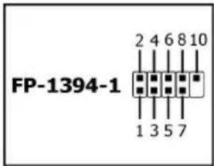
text_image
FP-1394-1 2 4 6 8 10 1 3 5 7| Pin | Pin Assignment | Pin | Pin Assignment |
| 1 TPA0 + 2 TPA0 - | |||
| 3 Ground | 4 | Ground | |
| 5 TPBO + 6 TPBO - | |||
| 7 +12V | 8 | +12V | |
| 10 | Ground |
※ Make sure the connecting cable bears the same pin assignment.
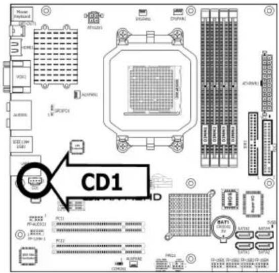
1.8.5 Internal Audio Connectors
This connector connects to the audio output of internal CD-ROM drive or add-on card.
text_image
CD1 PC11 PC22 COMPOS VISA/MS CPU/MS AC/MS DC/MS VISA/MS CPU/MS AC/MS DC/MS VISA/MS CPU/MS AC/MS DC/MS VISA/MS CPU/MS AC/MS DC/MS VISA/MS CPU/MS AC/MS DC/MS VISA/MS CPU/MS AC/MS DC/MS VISA/MS CPU/MS AC/MS DOSI COMPOS COMPOS COMPOS COMPOS COMPOS COMPOS COMPOS COMPOS COMPOS COMPOS COMPOS COMPOS COMPOS COMPOS COMPOS COMPOS COMPOS COMPOS COMPOS COMPOS COMPOS COMPOS COMPOS COMPOS COMPOS COMPOS COMPOS COMPOS COMPOS COMPOS COMPOS COMPOS COMPOS COMPOS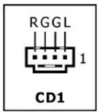
text_image
RGGL 1 CD11.8.6 Front Panel Audio Connection Header
This header provides the front panel connection for HD (High Definition) Audio, yet for AC'97 Audio CODEC connection, you must carefully check the pin assignment before connecting from the front panel module. An incorrect connection may cause malfunction or even damage the motherboard.
※ Please do not connect the "Ground" cable or "USB VCC" cable from the front panel module to the Pin 4 "AVCC" of this header.
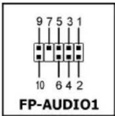
text_image
9 7 5 3 1 10 6 4 2 FP-AUDIO1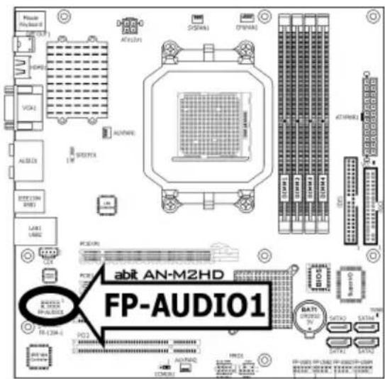
text_image
Mac PlayBoard OUT VCA1 ALABEX ORDER ON LINE LAB1 LINE ACI01 ACI02 COM50 CP00 CP01 CP02 CP03 CP04 CP05 CP06 CP07 CP08 CP09 CP10 CP11 CP12 CP13 CP14 CP15 CP16 CP17 CP18 CP19 CP20 CP21 CP22 CP23 CP24 CP25 CP26 CP27 CP28 CP29 CP30 CP31 CP32 CP33 CP34 CP35 CP36 CP37 CP38 CP39 CP40 CP41 CP42 CP43 CP44 CP45 CP46 CP47 CP48 CP49 CP50 abit AN-M2HD FP-AUDIO1| Pin | Pin Assignment (HD AUDIO) |
| 1 MIC2 L 1 MIC In | |
| 2 | AGND |
| 3 MIC2 R 3 MIC Power | |
| 4 AVCC 4 N | |
| 5 FRO-R 5 Line O | |
| 6 | MIC2_JD |
| 7 | F_IO_SEN |
| 9 | FRO-L 9 |
| 10 | LINE2_JD |
| Pin | Pin Assignment (AC'97 AUDIO) |
| 2 | GND |
| C | |
| (R) | |
| 6 | NC |
| 7 | NC |
| Line Out (L) | |
| 10 | NC |
Driver Configuration for AC'97 audio connection:
The audio driver is originally configured to support HD Audio. For AC'97 audio connection, you may:
- Right-click the "Realtek HD Audio Manager" icon in system tray.

text_image
Sound Manager Full Media Windows PiRus Player Sound Explorer Volume Control- Click "Audio I/O" tab, and then click "Connector Settings".
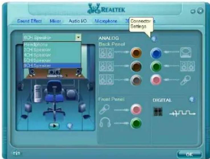
text_image
REALTEK Sound Effect Mixer Audio I/O Microphone 3D Connector Settings BCH Speaker Headphone BCH Speaker 4CH Speaker 6CH Speaker BCH Speaker ANALOG Back Panel Front Panel DIGITAL OK- Click "Disabled front panel jack detection", and then click "OK" to confirm.
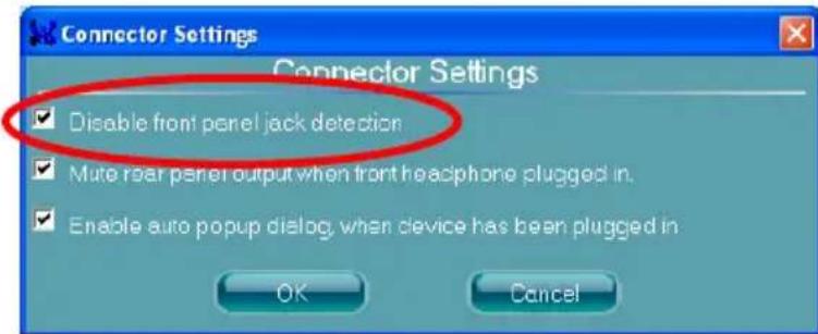
text_image
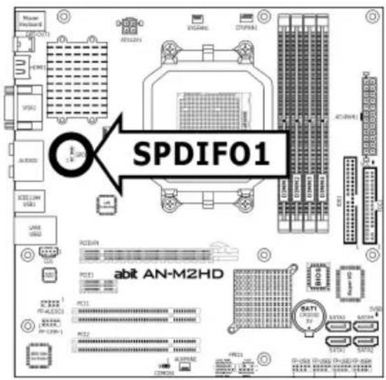
Connector Settings Disable front panel jack detection Mute rear panel output when front headphone plugged in. Enable auto popup dialog, when device has been plugged in OK Cancel1.8.7 S/PDIF Output Connection Header
This header provides the S/PDIF output connection to your add-on HDMI VGA card. (For AN-M2HD only)
text_image
Master (800000000) VDDI VSSU VSSU VSSU VSSU VSSU VSSU VSSU VSSU VSSU VSSU VSSU VSSU VSSU VSSU VSSU VSSU VSSU VSSU VSSU VSSU VSSU VSSU VSSU VSSU VSSU VSSSU VSSSU VSSSU VSSSU VSSSU VSSSU VSSSU VSSSU VSSSU VSSSU VSSSU VSSSU VSSSU VSSSU VSSSU VSSSU VSSSU VSSSU VSSSU VSSSU VSSSU VSSSU VSSSU VSSSU VSSSU VSSSUD VSSSUD VSSSUD VSSSUD VSSSUD VSSSUD VSSSUD VSSSUD VSSSUD VSSSUD VSSSUD VSSSUD VSSSUD VSSSUD VSSSUD VSSSUD VSSSUD VSSSUD VSSSUD VSSSUD VSSSUSD VSSSUSD VSSSUSD VSSSUSD VSSSUSD VSSSUSD VSSSUSD VSSSUSD VSSSUSD VSSSUSD VSSSUSD VSSSUSD VSSSUSD VSSSUSD VSSSUSD VSSSUSD VSSSUSD VSSSUSD VSSSUSD VSSSUSD VSSSUSDA VSSSUSDA VSSSUSDA VSSSUSDA VSSSUSDA VSSSUSDA VSSSUSDA VSSSUSDA VSSSUSDA VSSSUSDA VSSSUSDA VSSSUSDA VSSSUSDA VSSSUSDA VSSSUSDA VSSSUSDA VSSSUSDA VSSsEADH 1.5kΩ/1.5kΩ/1.5kΩ/1.5kΩ/1.5kΩ/1.5kΩ/1.5kΩ/1.5kΩ/1.5kΩ/1.5kΩ/1.5kΩ/1.5kΩ/1.5kΩ/1.5kΩ/1.5kΩ/1.5kΩ/1.5kΩ/1.5mΩ/1.5mΩ/1.5mΩ/1.5mΩ/1.5mΩ/1.5mΩ/1.5mΩ/1.5mΩ/1.5mΩ/1.5mΩ/1.5mΩ/1.5mΩ/1.5mΩ/1.5mΩ/1.5mΩ/1.5mΩ/1.5mΩ/1. SPDIF01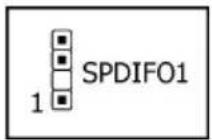
| Pin Pin Assignment | |
| 1 | VCC (5V) |
| 2 | x |
| 3 | S/PDIF Out |
| 4 | Ground |
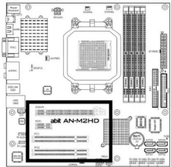
1.8.8 PCI and PCI Express X16, X1 Slots
Install PCI Express X16 graphics card into slot "PCIEXP1".
Install PCI Express X1 cards into slot "PCIE1".
Install PCI cards into slots "PCI1", and/or "PCI2".
text_image
Master Keyboard 1 HDMI VCC1 ALUMOS IEEE LIM USB1 LANE 3750 3750 3750 3750 3750 3750 3750 3750 3750 3750 3750 3750 3750 3750 3750 3750 3750 3750 3750 3750 3751 ACI-ANM1 ACI-ANM2 ACI-ANM3 ACI-ANM4 ACI-ANM5 ACI-ANM6 ACI-ANM7 ACI-ANM8 ACI-ANM9 ACI-ANM10 ACI-ANM11 ACI-ANM12 ACI-ANM13 ACI-ANM14 ACI-ANM15 ACI-ANM16 ACI-ANM17 ACI-ANM18 ACI-ANM19 ACI-ANM20 ACI-ANM21 ACI-ANM22 ACI-ANM23 ACI-ANM24 ACI-ANM25 ACI-ANM26 ACI-ANM27 ACI-ANM28 ACI-ANM29 ACI-ANM30 ACI-ANM31 ACI-ANM32 ACI-ANM33 ACI-ANM34 ACI-ANM35 ACI-ANM36 ACI-ANM37 ACI-ANM38 ACI-ANM39 ACI-ANM40 ACI-ANM41 ACI-ANM42 ACI-ANM43 ACI-ANM44 ACI-ANM45 ACI-ANM46 ACI-ANM47 ACI-ANM48 ACI-ANM49 ACI-ANM50 acit AN-M2HD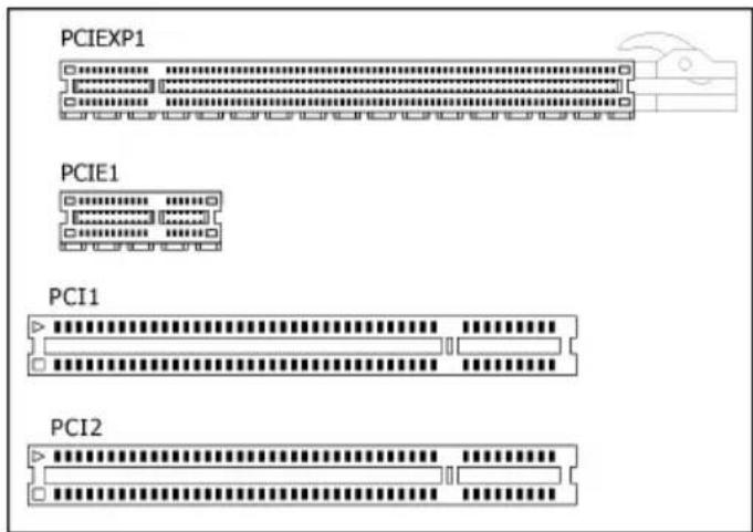
text_image
PCIEXP1 PCIE1 PCI1 PCI21.9 Onboard Indicators
1.9.1 Power Source Indicators
• 5VSB: This LED lights up when the power supply is connected with power source.
• VCC: This LED lights up when the system power is on.

text_image
VCC 5VSB abit AN-M2HD 5VSB1.10 Connecting Rear Panel I/O Devices
The rear I/O part of this motherboard provides the following I/O ports:
AN-M2
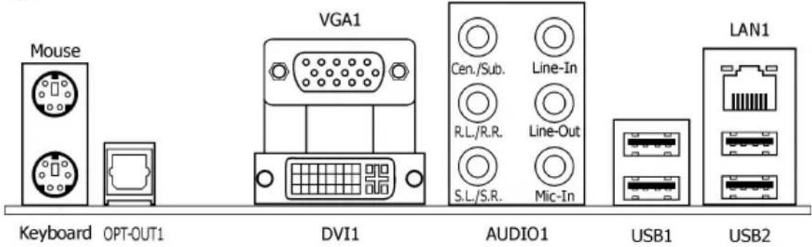
text_image
Mouse Keyboard OPT-OUT1 VGA1 DVI1 Cen./Sub. R.L./R.R. S.L./S.R. Line-In Line-Out Mic-In AUDIO1 USB1 LAN1 USB2AN-M2HD
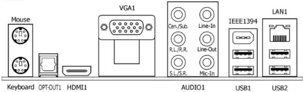
text_image
Mouse Keyboard OPT-OUT1 HDMI1 VGA1 Cen./Sub. Line-In R.L./R.R. Line-Out S.L./S.R. Mic-In AUDIO1 IEEE1394 USB1 LAN1 USB2- Mouse: Connects to PS/2 mouse.
• Keyboard: Connects to PS/2 keyboard. - OPT-OUT1: This connector provides an S/PDIF-Out connection through optical fiber to digital multimedia devices.
• HDMI1: Connects to multimedia devices of HDMI protocol. (For AN-M2HD only)
To enable this HDMI function, you will have to select "HD Audio rear output" as the sound playback device in the "Sounds and Audio Devices Properties" by Windows' Control Panel.
• VGA1/DVI1: Connects to monitor input.
- AUDIO1:
Cen./Sub. (Center / Subwoofer): Connects to the center and subwoofer channel.
R.L./R.R. (Rear Left / Rear Right): Connects to the rear left and rear right channel.
S.L./S.R. (Surround Left / Surround Right): Connects to the surround left and surround right channel.
Line-In: Connects to the line out from external audio sources.
Line-Out: Connects to the front left and front right channel.
Mic-In: Connects to the plug from external microphone.
• LAN1: Connects to Local Area Network.
- IEEE1394: Connects to devices of IEEE1394 protocol. (For AN-M2HD only)
- USB1/USB2: Connects to USB devices such as scanner, digital speakers, monitor, mouse, keyboard, hub, digital camera, joystick etc.
2. BIOS Setup
This motherboard provides a programmable EEPROM so that you can update the BIOS utility. The BIOS (Basic Input/Output System) is a program that deals with the basic level of communication between processor and peripherals. Use the BIOS Setup program only when installing motherboard, reconfiguring system, or prompted to "Run Setup". This chapter explains the Setup Utility of BIOS utility.
After powering up the system, the BIOS message appears on the screen, the memory count begins, and then the following message appears on the screen:
PRESS DEL TO ENTER SETUP
If this message disappears before you respond, restart the system by pressing keys, or by pressing the Reset button on the computer chassis. Only when these two methods fail should you restart the system by powering it off and then back on.
After pressing key, the main menu screen appears.
| Phoenix - AwardBIOS CMOS Setup Utility | |
| ► SoftMenu Setup► Standard CMOS Features Load Fail-Safe Defaults► Advanced BIOS Features Load Optimized Defaults► Advanced Chipset Features Set Password► Integrated Peripherals Save & Exit Setup► Power Management Setup Exit Without Saving► PnP/PCI Configurations | ► PC Health Status |
| Esc: Quit ↑↓→← : Select ItemF10: Save & Exit Setup (NF-MCP68S-6A61MA1AC-00) | |
| Change CPU's Clock & Voltage | |
※ In order to increase system stability and performance, our engineering staff is constantly improving the BIOS menu. The BIOS setup screens and descriptions illustrated in this manual are for your reference only, and may not completely match with what you see on your screen.
2.1 SoftMenu Setup
This option configures the CPU's clock and voltage.
Phoenix - AwardBIOS CMOS Setup Utility
SoftMenu Setup

AMD Athlon(tm) 64 X2 Dual Core Processor 4800+ Item Help
Frequency : 2400MHz

CPU Operating Speed Default
x - CPU External Clock(MHz) 200MHz
x - PCIe Clock 100MHz
x - Multiplier Factor x12

Voltages Control Default
x - CPU Core Voltage 1.300 V
x - DDR2 Voltage 1.85 V

↑↓→←:Move Enter:Select +/-/PU/PD:Value F10:Save ESC:Exit F1:General Help
F5: Previous Values F6: Fail-Safe Defaults F7: Optimized Defaults
Brand Name
This item displays the CPU model name installed on this motherboard.
Frequency
This item displays the processor speed of the CPU installed on this motherboard.
CPU Operating Speed
This item displays the CPU operating speed according to the type and speed of your CPU. You can also select the [User Define] option to enter the manual option.
User Define:
※ The wrong settings of the multiplier and external clock in certain circumstances may cause CPU damage. Setting the working frequency higher than the PCI chipset or processor specs, may cause abnormal memory module functioning, system hangs, hard disk drive data lose, abnormal functioning of the VGA card, or abnormal functioning with other add-on cards. Using non-specification settings for your CPU is not the intention of this explanation. These should be used for engineering testing, not for normal applications.
※ There will be no guaranty for the settings beyond specification. Any damage of any component on this motherboard or peripherals resulting therein is not our responsibility.
- CPU External Clock(MHz)
This item selects the external clock frequency. Due to the specification limit of the CPU you installed, the speed you set over its standard bus speed is supported, but not guaranteed.
- PCIe Clock
This item selects the clock frequency for PCI Express slot.
- Multiplier Factor
This item displays the multiplier factor for the CPU you installed.
Voltages Control
This option allows you to switch between the default and user-defined voltages. Leave this setting at default unless the current voltage setting cannot be detected or is not correct. The option "User Define" enables you to select the following voltages manually.
- CPU Core Voltage
- DDR2 Voltage
2.2 Standard CMOS Features
| Phoenix - AwardBIOS CMOS Setup Utility Standard CMOS Features | |
| Date (mm:dd:yy) Wed, Apr 12 2007 Item Help Time (hh:mm:ss) 12 : 34 : 56 | |
| ▶ IDE Channel 1 Master None ▶ IDE Channel 1 Slave None ▶ SATA Channel 1 None ▶ SATA Channel 2 None ▶ SATA Channel 3 None ▶ SATA Channel 4 None | |
| Drive A 1.44M, 3.5 in. Drive B None Floppy 3 Mode Support Disabled Halt On All, But Keyboard | |
| Base Memory 640K Extended Memory 1047552K Total Memory 1047552K | |
| ↑↓→←:Move Enter:Select +/-/PU/PD:Value F10:Save ESC:Exit F1:General Help F5: Previous Values F6: Fail-Safe Defaults F7: Optimized Defaults | |
Date (mm:dd:yy)
This item sets the date you specify (usually the current date) in the format of [Month], [Date], and [Year].
Time (hh:mm:ss)
This item sets the time you specify (usually the current time) in the format of [Hour], [Minute], and [Second].

IDE Channel 1 Master/Slave, SATA Channel 1\~4
Click
| Phoenix - AwardBIOS CMOS Setup Utility IDE Channel 1 Master | ||
| IDE HDD Auto-Detection | Press Enter | Item Help |
| IDE Channel 1 Master Auto Access Mode | Auto | |
| Capacity | 0 MB | |
| Cylinder | 0 | |
| Head | 0 | |
| Precomp | 0 | |
| Landing Zone | 0 | |
| Sector | 0 | |
| ↑↓→←:Move Enter:Select +/-/PU/PD:Value F10:Save ESC:Exit F1:General Help F5: Previous Values F6: Fail-Safe Defaults F7: Optimized Defaults | ||
IDE HDD Auto-Detection
This item allows you to detect the parameters of IDE drives by pressing
IDE Channel 1 Master/Slave, SATA Channel 1\~4
When set to [Auto], the BIOS will automatically check what kind of IDE or SATA hard drive you are using. If you want to define your own drive yourself, set it to [Manual] and make sure you fully understand the meaning of the parameters. Please refer to the instruction manual provided by the device's manufacturer to get the setting right.
Access Mode
This item selects the mode to access your IDE or SATA devices. Leave this item at its default [Auto] setting to detect the access mode of your HDD automatically.
Capacity
This item displays the approximate capacity of the disk drive. Usually the size is slightly greater than the size of a formatted disk given by a disk-checking program.
Cylinder
This item configures the numbers of cylinders.
Head
This item configures the numbers of read/write heads.
Precomp
This item displays the number of cylinders at which to change the write timing.
Landing Zone
This item displays the number of cylinders specified as the landing zone for the read/write heads.
Sector
This item configures the numbers of sectors per track.

Back to Standard CMOS Features Setup Menu
Drive A & Drive B
This item sets the type of floppy drives (usually only Drive A) installed.
Floppy 3 Mode Support
This item allows you to use "3 Mode Floppy Drive" in Japanese computer systems by selecting drive A, B, or both. Leave this item at its default [Disabled] setting if you are not using this Japanese standard floppy drive.
Halt On
This item determines whether the system stops if an error is detected during system boot-up.
[All Errors]: The system-boot will stop whenever the BIOS detect a non-fatal error.
[No Errors]: The system-boot will not stop for any error detected.
[All, But Keyboard]: The system-boot will stop for all errors except a keyboard error.
[All, But Diskette]: The system-boot will stop for all errors except a diskette error.
[All, But Disk/Key]: The system-boot will stop for all errors except a diskette or keyboard error.
Base Memory
This item displays the amount of base memory installed in the system. The value of the base memory is typically 640K for systems with 640K or more memory size installed on the motherboard.
Extended Memory
This item displays the amount of extended memory detected during system boot-up.
Total Memory
This item displays the total memory available in the system.
2.3 Advanced BIOS Features
| Phoenix - AwardBIOS CMOS Setup Utility Advanced BIOS Features | |
| Quick Power On Self Test Enabled Item Help▶ Hard Disk Boot Priority Press EnterFirst Boot Device FloppySecond Boot Device Hard DiskThird Boot Device CDROMBoot Other Device EnabledBoot Up Floppy Seek DisabledBoot Up NumLock Status OnSecurity Option SetupMPS Version Ctrl For OS 1.4Delay IDE Initial (Secs) 0Full Screen LOGO Show Enabled | |
| ↑↓→←:Move Enter:Select +/-/PU/PD:Value F10:Save ESC:Exit F1:General HelpF5: Previous Values F6: Fail-Safe Defaults F7: Optimized Defaults | |
Quick Power On Self Test
When set to [Enabled], this item speeds up the Power On Self Test (POST) after powering on the system. The BIOS shorten or skip some check during the POST.
Hard Disk Boot Priority
This item selects the hard disks booting priority. By pressing
This item functions only when there is the option of [Hard Disk] in any one of the First/Second/Third Boot Device items.
First Boot Device / Second Boot Device / Third Boot Device / Boot Other Device
Select the drive to boot first, second and third in the [First Boot Device], [Second Boot Device], and [Third Boot Device] items respectively. The BIOS will boot the operating system according to the sequence of the drive selected. Set [Boot Other Device] to [Enabled] if you wish to boot from another device other than these three items.
Boot Up Floppy Seek
When set to [Enabled], the BIOS will check whether the floppy disk drive is installed or not.
Boot Up NumLock Status
This item determines the default state of the numeric keypad at system booting up.
[On]: The numeric keypad functions as number keys.
[Off]: The numeric keypad functions as arrow keys.
Security Option
This item determines when the system will prompt for password - every time the system boots or only when enters the BIOS setup.
[Setup]: The password is required only when accessing the BIOS Setup.
[System]: The password is required each time the computer boots up.
※ Don't forget your password. If you forget the password, you will have to open the computer case and clear all information in the CMOS before you can start up the system. But by doing this, you will have to reset all previously set options.
MPS Version Ctrl For OS
This item specifies which version of MPS (Multi-Processor Specification) this motherboard will use. Leave this item at its default setting.
Delay For HDD (Secs)
This item allows the BIOS to support some old or special IDE devices by prolonging this delay time. A larger value will give more delay time to the device for which to initialize and to prepare for activation.
Full Screen LOGO Show
This item determines to show the full screen logo when booting.
2.4 Advanced Chipset Features
| Phoenix - AwardBIOS CMOS Setup Utility Advanced Chipset Features | |
| K8<->NB HT Speed Auto Item HelpK8<->NB HT Width Auto▶DRAM Configuration Press Enter SSE/SSE2 Instructions Enabled iGPU Frame Buffer Control Autox - VGA Share Memory 64M | |
| ↑↓→←:Move Enter:Select +/-/PU/PD:Value F10:Save ESC:Exit F1:General HelpF5: Previous Values F6: Fail-Safe Defaults F7: Optimized Defaults | |
K8<->NB HT Speed
This item selects the LDT Bus Frequency between CPU and Chipset.
K8<->NB HT Width
This item selects the LDT Bus Width between CPU and Chipset.
DRAM Configuration
Click
You may manually set the DRAM timing parameters through its sub-items, or leave them at their default settings according to the SPD (Serial Presence Detect) data stored in the DRAM.
SSE/SSE2 Instructions
This item allows you to Enable or Disable the SSE/SSE2 (Streaming SIMD Extensions) instruction set.
iGPU Frame Buffer Control
This item allows you to control the VGA frame buffer size automatically or manually.
VGA Share Memory
This item selects the VGA share memory size.
※ The total system memory must be twice the size of this parameter at least, or else a lesser one will replace this parameter automatically by the BIOS utility itself. For example: In a 256M selection with 256M total system memory size configuration, the BIOS utility will force it down to 128M automatically.
In the applications that require higher frame buffer size, such as 3-D game, HDMI, or Blu-ray DVD playing, please select the option [256MB] for higher video performance.
2.5 Integrated Peripherals
| Phoenix - AwardBIOS CMOS Setup UtilityIntegrated Peripherals | |
| ► OnChip IDE/SATA Device Press Enter Item HelpInit Display First PCIeOnChip USB V1.1+V2.0- USB Keyboard Support OS- USB Mouse Support OSOnChip Audio Controller EnabledOnChip LAN Controller Enabled- OnChip LAN Boot ROM DisabledOnboard FDD Controller EnabledOnboard 1394 Controller Enabled | |
| ↑↓→←:Move Enter:Select +/-/PU/PD:Value F10:Save ESC:Exit F1:General HelpF5: Previous Values F6: Fail-Safe Defaults F7: Optimized Defaults | |

OnChip IDE/SATA Device
Click
| Phoenix - AwardBIOS CMOS Setup UtilityOnChip IDE/SATA Device | |
| IDE/SATA Function Setup Press EnterRAID Configuration Press Enter | Item Help |
| ↑↓→←:Move Enter:Select +/-/PU/PD:Value F10:Save ESC:Exit F1:General HelpF5: Previous Values F6: Fail-Safe Defaults F7: Optimized Defaults | |
Click
| Phoenix - AwardBIOS CMOS Setup Utility IDE/SATA Function Setup | |
| IDE 1 Controller Enabled Item Help IDE DMA Transfer Access Enabled OnChip SATA Controller Enabled | |
| ↑↓→←:Move Enter:Select +/-/PU/PD:Value F10:Save ESC:Exit F1:General Help F5: Previous Values F6: Fail-Safe Defaults F7: Optimized Defaults | |
IDE 1 Controller
This item allows you to enable or disable the IDE1 controller.
IDE DMA Transfer Access
This item selects the DMA mode for devices connected through IDE channels.
OnChip SATA Controller
This item enables or disables the onchip SATA controller.

RAID Configuration
Click
| Phoenix - AwardBIOS CMOS Setup Utility RAID Configuration | ||
| OnChip SATA Mode IDE Item Help | ||
| x - SATA1 RAID Disabled | ||
| x - SATA2 RAID Disabled | ||
| x - SATA3 RAID Disabled | ||
| x - SATA4 RAID Disabled | ||
| ↑↓→←:Move Enter:Select +/-/PU/PD:Value F10:Save ESC:Exit F1:General Help F5: Previous Values F6: Fail-Safe Defaults F7: Optimized Defaults | ||
OnChip SATA Mode
This item determines the mode for OnChip SATA.
[IDE]: The on-chip SATA served as IDE mode.
[RAID]: The on-chip SATA served as RAID mode.
- SATA1 RAID \~ SATA4 RAID
This item allows you to enable or disable the RAID function for each of the SATA1 \~ SATA4 port individually.

Back to Integrated Peripherals Setup Menu
Init Display First
This item allows you to choose the primary display card.
OnChip USB
This option enables or disables the USB controller.
- USB Keyboard Support
Select [BIOS] for the legacy operating system (such as DOS) that does not support USB keyboard.
- USB Mouse Support
Select [BIOS] for the legacy operating system (such as DOS) that does not support USB mouse.
OnChip Audio Controller
This option enables or disables the audio controller.
OnChip LAN Controller
This option enables or disables the LAN controller.
- OnChip LAN Boot ROM
This item allows you to use the boot ROM (instead of a disk drive) to boot-up the system and access the local area network directly.
Onboard FDD Controller
This option enables or disables the floppy disk controller.
Onboard 1394 Controller (For AN-M2HD only)
This option enables or disables the IEEE 1394 controller.
2.6 Power Management Setup
| Phoenix - AwardBIOS CMOS Setup Utility Power Management Setup | |
| ACPI Suspend Type S3(Suspend-To-RAM) Item Help - USB Resume from S3 Disabled Power Button Function Instant-Off Wake Up by WAKE# of PCIe Disabled Wake Up by PME# of PCI Disabled Wake Up by OnChip LAN Enabled Wake Up by Alarm Disabled X - Day of Month Alarm 0 X - Time(hh:mm:ss) Alarm 0 : 0 : 0 Cool'n'Quiet Technology Auto Restore On AC Power Loss Power Off HPET Support Enabled | |
| ↑↓→←:Move Enter:Select +/-/PU/PD:Value F10:Save ESC:Exit F1:General Help F5: Previous Values F6: Fail-Safe Defaults F7: Optimized Defaults | |
ACPI Suspend Type
This item selects the type of Suspend mode.
- USB Resume from S3
When set to [Enabled], this item allows you to use a USB device to wake up a system that is in the S3 (STR - Suspend To RAM) state. This item can be configured only if the item "ACPI Suspend Type" is set to [S3(STR)].
Power Button Function
This item selects the method of powering off your system:
[Delay 4 Sec.]: Pushing the power button for more than 4 seconds will power off the system. This will prevent the system from powering off in case you accidentally hit or pushed the power button.
[Instant-Off]: Pressing and then releasing the power button at once will immediately power off the system.
Wake Up by WAKE# of PCIe
When set to [Enabled], access through the add-on PCI Express card can remotely wake up the system that was in Soft-Off condition. The PCI Express card must support the wake up function.
Wake Up by PME# of PCI
When set to [Enabled], access through the add-on PCI card can remotely wake up the system that was in Soft-Off condition. The PCI card must support the wake up function.
Wake Up by OnChip LAN
When set to [Enabled], access through the onchip LAN port can remotely wake up the system that was in Soft-Off condition.
Wake Up by Alarm
When set to [Enabled], you can set the date and time you would like the Soft-Off PC to power-on in the "Date (of Month) Alarm" and "Time (hh:mm:ss) Alarm" items. However, if the system is being accessed by incoming calls or the network (Resume On Ring/LAN) prior to the date and time set in these items, the system will give priority to the incoming calls or network instead.
- Day of Month Alarm
[0]: This option power-on the system everyday according to the time set in the "Time (hh:mm:ss) Alarm" item.
[1-31]: This option selects a date you would like the system to power-on. The system will power-on on the date set, and the time set in the "Time (hh:mm:ss) Alarm" item.
- Time (hh:mm:ss) Alarm
This item sets the time you would like the system to power-on.
Cool 'n' Quiet Technology
This option enables or disables the AMD K8 cool and quiet function.
Restore On AC Power Loss
This item selects the system action after an AC power failure.
[Power Off]: When power returns after an AC power failure, the system's power remains off. You must press the Power button to power-on the system.
[Power On]: When power returns after an AC power failure, the system's power will be powered on automatically.
[Last State]: When power returns after an AC power failure, the system will return to the state where you left off before power failure occurred. If the system's power is off when AC power failure occurs, it will remain off when power returns. If the system's power is on when AC power failure occurs, the system will power-on when power returns.
HPET Support
This item selects to support the "High Precision Event Timer" (HPET), a new timer hardware for use by the system software when generating interrupts for thread schedulers, kernels, and multimedia timer servers.
2.7 PnP/PCI Configurations
| Phoenix - AwardBIOS CMOS Setup Utility PnP/PCI Configurations | |
| Resources Controlled By Auto(ESCD) Item Help x IRQ Resources Press Enter PCI/VGA Pallete Snoop Disbaled ** PCI Express relative items ** Maximum Payload Size 4096 | |
| ↑↓→←:Move Enter:Select +/-/PU/PD:Value F10:Save ESC:Exit F1:General Help F5: Previous Values F6: Fail-Safe Defaults F7: Optimized Defaults | |
Resources Controlled By
This item configures all of the boot and Plug-and-Play compatible devices.
[Auto(ESCD)]: The system will automatically detect the settings.
[Manual]: Choose the specific IRQ resources in the "IRQ Resources" menu.
- IRQ Resources
Click
This item sets each system interrupt to either [PCI Device] or [Reserved].
PCI/VGA Palette Snoop
This item determines whether the MPEG ISA/VESA VGA cards can work with PCI/VGA or not.
[Enabled]: MPEG ISA/VESA VGA cards work with PCI/VGA.
[Disabled]: MPEG ISA/VESA VGA cards do not work with PCI/VGA.
Maximum Payload Size
This item sets the maximum TLP payload size for the PCI Express devices.
2.8 PC Health Status
| Phoenix - AwardBIOS CMOS Setup UtilityPC Health Status | |
| CPU Shutdown Temperature 90 °C/194°FCPU Warning Temperature 80 °C/176°FFAN Fail Alarm Selectable DisabledShutdown When FAN Fail DisabledCPU FanEQ Control Enabled- CPU FanEQ Target Temp. 50 °C/122°F- CPU FanEQ Temp. Tolerance 5 °C/ 41°F- CPU FanEQ Start Control 80%- CPU FanEQ Stop Control 50%SYS FanEQ Control Enabled- SYS FanEQ Reference Temp. System- SYS FanEQ Target Temp. 35 °C/ 95°F- SYS FanEQ Temp. Tolerance 5 °C/ 41°F- SYS FanEQ Start Control 70%- SYS FanEQ Stop Control 50%CPU Temperature 42 °C/107°FSystem Temperature 30 °C/100°FPWM Temperature 42 °C/107°FCPU FAN Speed 3245 RPMSYS FAN Speed 0 RPMAUX1 FAN Speed O RPMAUX2 FAN Speed O RPMCPU Core Voltage 1.29 VDDR2 Voltage 1.87 VDDR2 VTT Voltage 0.91 VChipset Core Voltage 1.18 VATX +12V 12.00 VATX +3.3V 3.30 V | Item Help |
| ↑↓→←:Move Enter:Select +/-/PU/PD:Value F10:Save ESC:Exit F1:General HelpF5: Previous Values F6: Fail-Safe Defaults F7: Optimized Defaults | |
CPU Shutdown Temperature
You can set the processor shutdown temperature here. If the processor temperature exceeds the settings value, system will force to shutdown to protect the processor not overheat.
CPU Warning Temperature
This item lets you select the temperature at which you want the system to send out a warning message to the PC speakers of when the temperature goes beyond either limit. You can select the temperatures you want.
FAN Fail Alarm Selectable
This item selects the fan that will be monitored for malfunction.
Shutdown When FAN Fail
When set to [Enabled], the system will be shut down if the fan selected for monitoring is not running.
CPU FANEQ Control
This item allows you to control the CPU fan speed. When set to [Enabled], the following items become selectable.
- CPU FanEQ Target Temp.
This item sets the temperature mark for the "CPU FanEQ" function to take effect.
- CPU FanEQ Temp. Tolerance
This item sets the temperature tolerance range for the item "CPU FanEQ Target Temp.".
- CPU FanEQ Start Control
This item sets the speed ratio for the 4-pin CPU fan assembly connected at "CPUFAN1" fan power connector to start running.
- CPU FanEQ Stop Control
This item sets the lowest speed ratio for the 4-pin CPU fan assembly connected at "CPUFAN1" fan power connector to run at when the CPU temperature detected is lower than the value of item "CPU FanEQ Target Temp." plus the value of item "CPU FanEQ Temp. Tolerance".
In the situation when the CPU temperature detected is higher than the value of item "CPU FanEQ Target Temp." plus the value of item "CPU FanEQ Temp. Tolerance", the speed ratio for the 4-pin CPU fan assembly connected at "CPUFAN1" fan power connector will first run at the speed ratio set by the item "CPU FanEQ Start Control", and then up to 100% .
※ The 3-pin fan assembly connected at this 4-pin "CPUFAN1" fan power connector will have no speed control function.
SYS FanEQ Control
This item allows you to control the SYSFAN speed. When set to [Enabled], the following items become selectable.
- SYS FanEQ Reference Temp.
This item sets the reference point for taking temperature. The options are "System" and "CPU".
※ In the situation when connecting a 3-pin CPU fan assembly, and you still want the speed control function to take effect, you must:
-
Plug the 3-pin CPU fan assembly to "SYSFAN1" fan power connector.
-
Set the "SYS FanEQ Reference Temp." item from the default "System" to "CPU".
- SYS FanEQ Target Temp.
This item sets the temperature mark for the "SYS FanEQ" function to take effect.
- SYS FanEQ Temp. Tolerance
This item sets the temperature tolerance range for the item "SYS FanEQ Target Temp.".
- SYS FanEQ Start Control
This item sets the speed ratio for the 3-pin fan assembly connected at "SYSFAN1" fan power connector to start running.
- SYS FanEQ Stop Control
This item sets the lowest speed ratio for the 3-pin fan assembly connected at "SYSFAN1" fan power connector to run at when the temperature of "SYS FanEQ Reference Temp." detected is lower than the value of item "SYS FanEQ Target Temp." plus the value of item "SYS FanEQ Temp. Tolerance".
In the situation when the temperature of "SYS FanEQ Reference Temp." detected is higher than the value of item "SYS FanEQ Target Temp." plus the value of item "SYS FanEQ Temp.
Tolerance", the speed ratio for the 3-pin fan assembly connected at "SYSFAN1" fan power connector will first run at the speed ratio set by the item "SYS FanEQ Start Control", and then up to 100% .
All Voltages, Fans Speed and Thermal Monitoring
These unchangeable items list the current status of the CPU and environment temperatures, fan speeds, and system power voltage.
2.9 Load Fail-Safe Defaults
This option loads the BIOS default values for the most stable, minimal-performance system operations.
2.10 Load Optimized Defaults
This option loads the BIOS default values that are factory settings for optimal-performance system operations.
2.11 Set Password
This option protects the BIOS configuration or restricts access to the computer itself.
2.12 Save & Exit Setup
This option saves your selections and exits the BIOS setup menu.
2.13 Exit Without Saving
This option exits the BIOS setup menu without saving any changes.
3. Driver & Utility
The "Driver-&-Utility CD" that came packed with this motherboard contains drivers, utilities and software applications required for its basic and advanced features.
3.1 CD-ROM AUTORUN
To run the CD-ROM automatically:
-
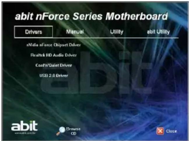
Place the "Driver-&-Utility CD" into the CD-ROM drive in your system. The following installation auto-run screen appears. If not, browse the root directory of the CD-ROM via the File Manager, and double click the "AUTORUN" file.
-
Click the item needed for installation.
-
[Drivers]: Click to enter the driver installation menu.
- [Manual]: Click to enter the user's manual menu.
• [Utility]: Click to enter the utilities installation menu. - [abit Utility]: Click to enter the installation menu of utilities exclusively developed by abit.
- [ Browse CD: Click to browse the contents of this "Driver-&-Utility CD".
- [ ✗ Close Close]: Click to exit this installation menu.
- The Windows will automatically search for current and updated software by looking up your computer.
When this "Found New Hardware Wizard" window appears. Click [Cancel] to start the following procedures.
text_image
abit nForce Series Motherboard Drivers Manual Utility abit Utility nVidia nForce Chipset Driver Realtek HD Audio Driver CoolPin'Qialet Driver USB 2.0 Driver abit Browse CD Close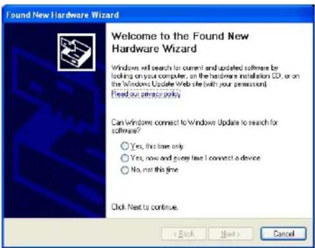
text_image
Found New Hardware Wizard Welcome to the Found New Hardware Wizard Windows will search for current and updated software by looking on your computer, on the hardware installation CD, or on the Windows Update Web site (with your permission). Fied out privacy policy Can Windows connect to Windows Update to search for software? Yes, this time only Yes, now and every time I connect a device No, not this time Click Next to continue. < Back Next > Cancel3.2 nVidia nForce Chipset Driver
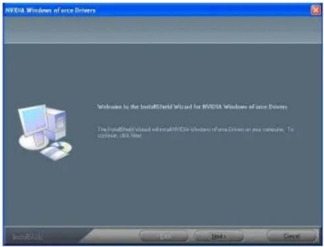
To install this program:
-
Click on the [Drivers] tab in the installation menu screen.
-
Click the [nVidia nForce Chipset Driver] item. The installation screen appears.
-
Follow the prompts on the screen to complete installation.
※ Please install this nVidia nForce Chipset Driver first after having installed the Windows operating system.
text_image
NVIDIA Windows nForce Drivers Welcome to the InstallShield Wizard for NVIDIA Windows of once Drivers The InstallShield Wizard will install NVIDIA Windows nForce Drivers on your computer. To continue, OK, Next. InstallShield3.3 Realtek HD Audio Driver
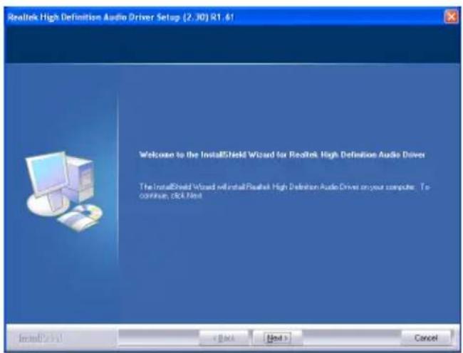
To install this program:
-
Click on the [Drivers] tab in the installation menu screen.
-
Click the [Realtek HD Audio Driver] item. The installation screen appears.
-
Follow the prompts on the screen to complete installation.
-
After restarting the system, right-click the Sound Manager icon located at the desktop shortcut. Click item "Sound Manager". The Realtek HD Audio Manager appears.
text_image
Realtek High Definition Audio Driver Setup (2.30) R1.61 Welcome to the InstallShield Wizard for Realtek High Definition Audio Driver The InstallShield Wizard will install Realtek High Definition Audio Driver on your computer. To continue, pick Next
text_image
7:51 AM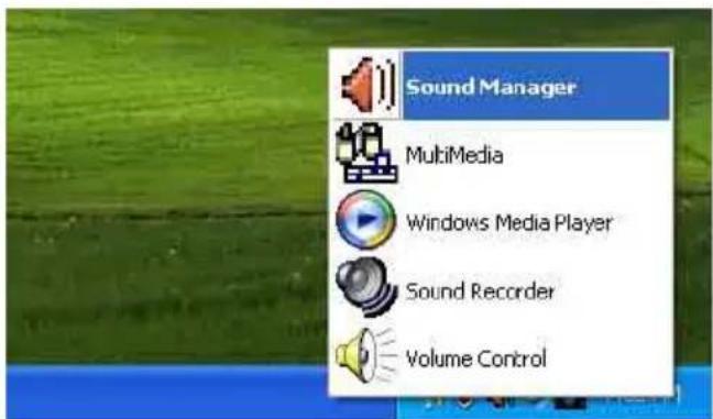
text_image
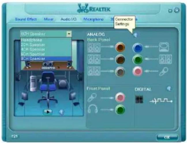
Sound Manager MultiMedia Windows Media Player Sound Recorder Volume Control- Click the [Audio I/O] tab.
- Click the pull down menu to select the channel configuration.
- Click [OK] button to apply the Audio I/O settings and exit.
text_image
REALTEK Sound Effect Mixer Audio/IO Microphone 3D Connector Settings 8CH Speaker Headphones 2CH Speaker 4CH Speaker 6CH Speaker 9CH Speaker ANALOG Back Panel 3.8 3.8 3.8 Front Panel DIGITAL OK3.4 Cool'n'Quiet Driver
To install this program:
- Click on the [Drivers] tab in the installation menu screen.
- Click the [Cool'n'Quiet Driver] item. The installation screen appears.
- Follow the prompts on the screen to complete installation.
-
Restart the system for the driver to take effect.
-
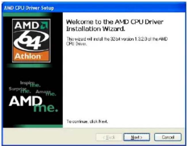
After the system restarted, open the "Power Options" from the control panel and choose the power scheme "Minimal Power Management" to enable Cool 'n' Quiet.
※ For Windows 2000 or ME system, an AMD Cool 'n' Quiet tab will appear under "Power Options" when the Cool 'n' Quiet software for Windows 2000 and ME is installed. This must be set to "Automatic Mode" for Cool 'n' Quiet to be enabled.
text_image
AMD CPU Driver Setup Welcome to the AMD CPU Driver Installation Wizard. This wizard will install the 32 bit version 1.3.2.0 of the AMD CPU Driver. To continue, click Next. < Back Next > Cancel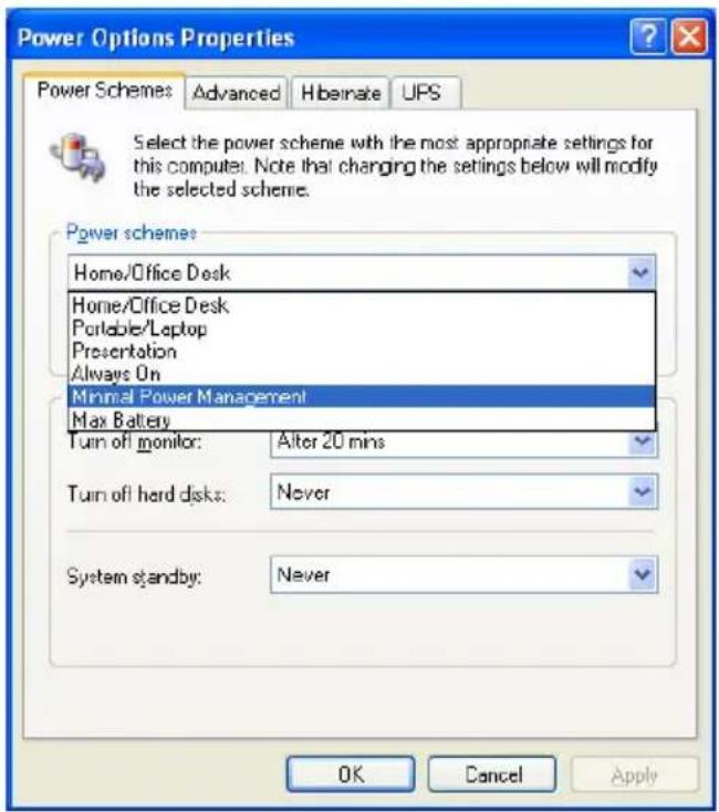
text_image
Power Options Properties Power Schemes Advanced Hibernate UPS Select the power scheme with the most appropriate settings for this computer. Note that changing the settings below will modify the selected scheme. Power schemes: Home/Office Desk Home/Office Desk Portable/Laptop Presentation Always On Minimal Power Management Max Battery Turn off monitor: Alter 20 mins Turn off hard disks: Never System standby: Never OK Cancel Apply3.5 USB 2.0 Driver
※ There is no need to install this driver for Windows 2000 with Service Pack 4, Windows XP with Service Pack 1, or their later version.
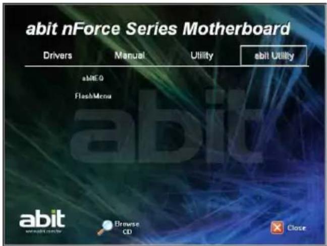
3.6 abitEQ (The Hardware Doctor Utility)
The abitEQ is a self-diagnostic system that protects PC Hardware by monitoring critical items of Power Supply Voltage, CPU & System Fans Speed, and CPU & System Temperature.
To install this utility:
-
Click on the [abit Utility] tab in the installation menu screen.
-
Click the [abitEQ] item. The following screen appears.
-
Follow the prompts on the screen to complete installation.
-
Execute the abitEQ by entering the Windows Menu [Start] → [All Programs] → [abit] → [abitEQ].
-
The abitEQ shows you the status of Voltage, Fan Speed, and Temperature readings as well.
text_image
abit nForce Series Motherboard Drivers Manual Utility abit Utility abITE0 FlashMenu abit Browse CD Close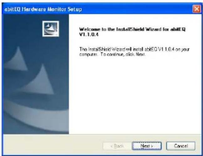
text_image
abitEQ Hardware Monitor Setup Welcome to the InstallShield Wizard for abitEQ V1.1.0.4 The InstallShield Wizard will install abitEQ V1.1.0.4 on your computer. To continue, click Next. < Back Next > Cancel
text_image
abit EQ Temperature Voltage Fan Item Value Warning Status CPU 25 °C 80 °C OK SYS 31 °C 60 °C OK PWM 37 °C 100 °C OK FANEG Fan EQ Item Current PWN Duty Cycle CPU/FAN 60% SYS FAN 100% abit abit EQ3.7 FlashMenu (BIOS Update Utility)
The FlashMenu is a utility to flash the BIOS in a more easily and quickly way.
To install this utility:
- Click on the [abit Utility] tab in the installation menu screen.
- Click the [ FlamshMenu ] item. The following screen appears.
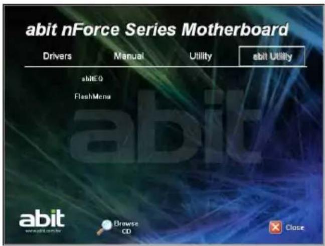
text_image
abit nForce Series Motherboard Drivers Manual Utility abit Utility abITE0 FlashMenu abit abit webalt.com Browse CD Close- Follow the prompts on the screen to complete installation.
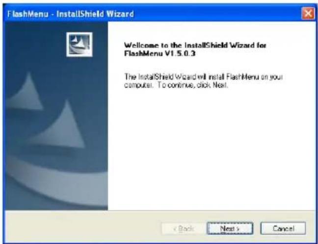
text_image
FlashMenu - InstallShield Wizard Welcome to the InstallShield Wizard for FlashMenu V1.5.0.3 The InstallShield Wizard will install FlashMenu on your computer. To continue, click Next.-
Execute the FlashMenu by entering the Windows Menu [Start] → [All Programs] → [abit] → [FlashMenu] → [FlashMenu].
-
This FlashMenu screen appears. You can easily update the BIOS from clicking [Update From File], [One Click LiveUpdate], or [LiveUpdate Step by Step] button.
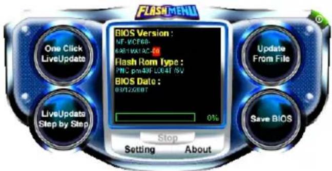
text_image
FLASH MENU One Click LiveUpdate LiveUpdate Step by Step BIOS Version : NF-VCF68- 6AS11061AC-50 Flash Rom Type : PNC pm4NF L004T /SV BIOS Date : 03/12/2007 Stop Setting About Update From File Save BIOS3.8 SATA RAID Driver (for Windows Vista)
The Raid Driver needed when installing Windows Vista operating system is located at the following path of your CD-ROM drive after placing the "Driver-&-Utility CD" into it:
For Vista 32bit → CD-ROM Drive:\Drivers\SATARAID\MCP68\Vista32
For Vista 64bit → CD-ROM Drive:\Drivers\SATARAID\MCP68\Vista64
3.9 SATA RAID Driver (for Windows XP, 2003, or 2000)
The "Driver Disk Maker" program bundled in the Driver-&-Utility CD is a utility to build the driver program needed for SATA controller into a floppy disk under DOS environment. This procedure is necessary only for installing Windows operating system to the hard disk connected to "SATA1\~SATA4" connector.
To create a driver disk Under DOS Environment:
- Before starting, connect a 3.5" floppy disk drive to the "FDC1" connector, and connect a CD-ROM drive to your motherboard. Prepare a 3.5" floppy disk.
- After completing all the start-up preparation for hardware setup, power on the system.
- Enter the BIOS Setup Menu by hitting
key ^1 .
Enter and select the BIOS menu "Advanced BIOS Features". Configure the option "First Boot Device" to "CD-ROM" ^2 drive. Save this selection and exit BIOS setup menu by accessing the BIOS menu "Save & Exit Setup".
- Restart the system. The system will now boot from CD, and enter the ABIT Boot Manager, the following options appear ^3 :
(0) Boot From First HDD
(1) Make Driver Disk
(2) Boot From First Floppy Drive
(3) Skip CD-ROM Boot (Try Next Boot Device)
Type <1> and hit
(1) Make Driver Disk
(2) Exit
Type <1> and hit
- The driver options appear:
(1) NVRaid Floppy Disk for WinXP_2K_2003 (32bit)
(2) NVRaid Floppy Disk for WinXP_2003 (64bit)
Type the number of the actions you want and hit
- Insert floppy disk to the floppy drive ^4 . Press any key to continue.
- Copying files to floppy now starts. After completed copying, hit the
key if you do not want to make another Driver Disk, and stop at the A:> prompt. - Take out the Driver-&-Utility CD from the CD-ROM drive now. Restart your system ^5 .

text_image
MEMO4. Multilingual Quick Installation Guide
Lüfteranschlüsse (FAN): [CPUFAN1], SYSFAN1, AUXFAN1, [NBFAN1]
Interne Audioanschlüsse: [CD1], [AUX1]
Instalar a placa principal no chassis
Para instalar a placa principal no chassis, deve:
Connectivity and Exploration of the Chinese Language (COS) in China is a key language for the use of the Chinese Language. The English Language is also a Chinese Language, but it is not a Chinese language.
- 1個PCI-E X16插槽
- 1個PCI-E X1插槽
- 2個PCI插槽
內部輸入/輸出接頭
5.1 Troubleshooting (How to Get Technical Support?)
5.1.1 Q & A
Q: Do I need to clear the CMOS before I use a new motherboard to assemble my new computer system?
A: Yes, we highly recommend that you clear the CMOS before installing a new motherboard. Please move the CMOS jumper from its default 1-2 position to 2-3 for a few seconds, and then back. When you boot up your system for the first time, follow the instructions in the user's manual to load the optimized defaults.
Q: If my system hangs when I update the BIOS or set the wrong CPU parameters, what should I do?
A: Whenever you update the BIOS or if the system hangs due to wrong CPU parameters setting, always clear CMOS jumper before booting up again.
Q: Why does the system fail to boot up again right after a mechanical power-off?
A: Please keep a 30-second interval between each mechanical power On/Off.
Q: Why does the system fail to boot up and nothing displays on the screen after I did some over-clocking or non-standard settings inside the BIOS?
A: It should not cause hardware or permanent damage to motherboard when BIOS settings were changed from default to over-clocking or non-standard status.
We suggest the following three troubleshooting methods to discharge CMOS data, recover the hardware default status, and then making the motherboard work again. There is no need to bother returning the motherboard to where you bought it from or go through an RMA process.
Step 1. Switch off the power supply unit and then switch it on again after one minute. If there is no power-switch on the power supply unit, disconnect its power cord for one minute and then reconnect.
Press and hold the key to enter the BIOS setup page to apply the correct settings.
If the situation remains the same, repeat the procedures in Step 1 three times, or try Step 2.
Step 2. Switch off the power supply unit or disconnect the power cord. Open the chassis cover. Locate the CCMOS jumper near the button battery. Change the jumper position from default 1-2 to 2-3 for one minute to discharge the CMOS data, and then put it back to default 1-2 position.
Close the chassis and switch on the power supply unit or plug in the power cord. Press the power-on button to boot up system. If it works, hit key to enter the BIOS setup page to do the correct settings.
If the situation remains the same, try Step 3.
Step 3. The same procedure as Step 2, but while discharging the CMOS data, pull out the ATX power connectors from motherboard and remove the button battery during CMOS discharge.
Q: How to get a quick response for my request on technical support?
A: Please carry out a simple troubleshooting before sending "Technical Support Form":
System boot-up fails after the system had been assembled:
Check the motherboard's supporting specifications first to see if all the key components attached in your system can meet.
To do so, you may:
- Remove all the unnecessary add-on devices (except the CPU, VGA card, DRAM, and Power Supply), and then reboot.
- If the trouble still exists, try another VGA card of different brand/model to see if the system will start.
- If the trouble still exists, try another memory module of different brand/model.
- If the trouble still exists, try another CPU and Power Supply.
If the system runs successfully, shut it down and start re-installing the interface cards and devices that were previously installed in the system. Re-install and start the system one at a time until the system won't start.
Malfunction in the OS:
If the system hangs after resuming from S3 or some testing program, if the CPU cannot be recognized properly, if the display resolution mixed, or if a certain program cannot be executed, etc, you may:
- Upgrade the motherboard's latest BIOS version.
- Upgrade the add-on device's latest driver version.
- Check if there is any conflict in the "Control Panel/System Properties".
Q: How to fill in the "Technical Support Form"?
A: To fill in this "Technical Support Form", please refer to the following instructions:
• Region: Type in your country name.
• E-mail: Type in your contact E-mail information.
- First name: Type in your first name.
• Last name: Type in your last name.
- Subject: Type in the model name and the problem of your motherboard.
Example 1: AA8XE and SCSI 29160 malfunction
Example 2: AA8XE boot fails, POST code AF
Example 3: AA8XE (system hang when S3 resume)
- Motherboard: Type in the model name and revision number of your motherboard. Example: AA8XE REV: 1.00
- BIOS Version: Type in the BIOS version of your motherboard. (You can find it on the screen during the POST sequence.)
- CPU: Type in the brand name and the speed (MHz) of your CPU. (Illustrate the over-clocking status if you had done so.)
Example: Intel 650 3.4GHz (OC FSB=220MHz)
• Memory brand: Type in the brand and model name of your memory module.
Example: Memory brand: Kingston (KVR533D2N4/1G)
• Memory size: Type in the size of your memory module.
Example: 512M* 4PCS
- Memory configuration: Type in the memory configuration in BIOS setting. Example: Memory Timing: 2.5-3-3-7 @533MHz
- Graphics information: Note Graphics card's brand, model and driver version
- Graphics card: Type in the brand and model name of your graphics card. Example: ATI RADEON X850 XT PE
- Graphics driver version: Type in the driver version of your graphics card
Example: Catalyst 5.12V
• Power supply maker: Type in the brand and model name of your power supply unit.
• Power supply wattage: Type in the power wattage of your power supply unit. - Storage devices: Type in the brand and specifications of your HDD drive and quantity. Specify if it was inserted on IDE (Master or Slave) or SATA ports, including the RAID allocation status.
Example 1: WD Caviar WD600 60GB (on IDE2 master), Maxtor DiamondMax 10 SATA 300GB (on SATA 3)
Example 2: Maxtor DiamondMax 10 SATA 300GB *2 (on SATA 3, SATA 4 RAID 1)
- Optical devices: Type in the brand and specifications of your optical drives and quantity. Specify if it was inserted on IDE (Master or Slave) or SATA ports.
- Other devices: Indicate which add-on cards or USB devices you are absolutely sure relate to the problem. If you cannot identify the problem's origin, indicate all the add-on cards or USB devices inserted on your system.
Example: AHA 29160 (on PCI 2), Sandisk Cruzer mini 256MB USB Flash-disk.
- Operating system: Indicate which OS and language version
Example: Microsoft Windows XP SP2, English version
Example: Microsoft Media Center Edition 2005, Korean version
- Problem description: Describe the problem of your system configuration. Indicate the steps to duplicate problem if possible.
See the next page for a blank Technical Support Form, or visit our website to fill in the form on line (http://www.abit.com.tw/page/en/contact/technical.php).
Q. Is the motherboard dead? Do I need to return it to where I bought from or go through an RMA process?
A: After you have gone through the troubleshooting procedures, yet the problem still exists, or you find an evident damage on the motherboard, please contact our RMA center. (http://www2.abit.com.tw/page/en/contact/index.php?pFUN_KEY=18000&pTITLE_IMG)
5.1.2 Technical Support Form
| Region: | |
| E-mail: | |
| First name: | |
| Last Name: | |
| Subject: | |
| Motherboard: | |
| BIOS Version: | |
| CPU: | |
| Memory brand: | |
| Memory size: | |
| Memory configuration: | |
| Graphics card: | |
| Graphics driver version: | |
| Power supply maker: | |
| Power supply wattage: | |
| Storage devices: | |
| Optical devices: | |
| Other devices: | |
| Operating system: | |
| Problem description: |
5.1.3 Contact Information
Taiwan Head Office Universal ABIT Co., Ltd.
6F, No. 323, Yang Guang St., Neihu, Taipei, 114, Taiwan
Tel: 886-2-8751-3380
Fax: 886-2-8751-3381
Sales: sales@abit.com.tw
Marketing: market@abit.com.tw
North America, South America
Universal ABIT (USA) Corporation
2901 Bayview Drive, Fremont, CA 94538, U.S.A.
Tel: 1-510-623-0500
Fax: 1-510-623-1092
Website: http://www.abit-usa.com
Latin America: raymond@abit-usa.com
RMA Center: http://rma.abit-usa.com
UK, Ireland
Universal ABIT UK Co. Ltd.
Unit 3, 24-26 Boulton Road, Stevenage, Herts SG1 4QX, United Kingdom
Tel: +44-1438-228888
Fax: +44-1438-226333
For technical support and RMA return:
Tel: +44-1438-362088
technical@abitcomputer.co.uk
returns@abitcomputer.co.uk
Germany and Benelux (Belgium, Netherlands, Luxembourg), France, Italy, Spain, Portugal, Greece, Denmark, Norway, Sweden, Finland, Switzerland
Universal ABIT NL B.V.
Jan van Riebeeckweg 15, 5928LG, Venlo, The Netherlands
Tel: 31-77-3204428
Fax: 31-77-3204420
Chamber of Commerce Venlo – number 12062448
Austria, Czech, Romania, Bulgaria, Slovakia, Croatia, Bosnia, Serbia, Macedonia, Slovenia
Universal ABIT Austria Computer GmbH
Schmalbachstrasse 5, A-2201 Gerasdorf / Wien, Austria
Tel: 43-1-7346709
Fax: 43-1-7346713
Contact: office@abit-austria.at
Website: http://www.abit-austria.at
Shanghai
Universal ABIT (Shanghai) Co. Ltd.
FL 19 Xuhui Yuan BLOG NO.1089
ZhongShan s 2 RD, ShangHai 200030
The People's Republic of China
Tel: (86-21) 54102211
Fax: (86-21) 54104791
Website: http://www.abit.com.cn
Poland
Universal ABIT Poland (Rep. office)
Strzegomska 310/2, 54-432 Wrocław
Tel: +48-71-718-12-39
Fax: +48-71-718-12-38
Contact: gmorgiel@abit.com.tw
Turkey
Universal ABIT Turkey (Rep. office)
Tel: 90 532 211 6860
Iran
Universal ABIT (Rep. office)
No.50, Valiasr Computer Center, Valiasr St. Tehran Iran
Tel: 98-21-88944287
Fax: 98-21-88941655
Contact: alireza_khoshdel@abit.com.tw
abit
UNIVERSAL ABIT Co., Ltd.
http://www.abit.com.tw